1
ふ
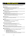
Multi Function Weighing Indicator
WM : PD4000243A
This is a hazard alert mark.
This mark informs you about the operation of the product.
Note This manual is subject to change without notice at any time to improve the product. No part of this
manual may be photocopied, reproduced, or translated into another language without the prior
written consent of the A&D Company.
Product specifications are subject to change without any obligation on the part of the manufacture.
Contents
1.
Compliance........................................................................................ 4
1.1.1.
Compliance with FCC rules ....................................................... 4
1.1.2.
Compliance with European Directives....................................... 4
2.
Outline and Features ......................................................................... 5
2.1.
Precaution ..................................................................................... 6
2.2.
Front Panel .................................................................................... 7
2.2.1.
Keys .......................................................................................... 7
2.2.2.
Symbols..................................................................................... 8
2.3.
Rear Panel................................................................................... 10
3.
Installation........................................................................................ 11
3.1.
Mounting Indicator ....................................................................... 11
3.2.
Connecting Loadcell Cable.......................................................... 12
3.2.1.
Verifying Loadcell Output and Input Sensitivity ....................... 13
3.3.
Wiring Power Cord ...................................................................... 14
3.4.
Installing Options ......................................................................... 15
4.
Basic Operation ............................................................................... 16
4.1.
Key Operation Examples ............................................................. 16
4.1.1.
Standby Mode ......................................................................... 16
4.1.2.
Cursor Operation..................................................................... 16
4.1.3.
Inputting Characters ................................................................ 16
4.1.4.
The Way of Calling a Code...................................................... 17
4.1.5.
The Way of Entering a Correction Mode ................................. 17
4.1.6.
The Way of Entering The Menu............................................... 18
4.2.
Status Chart (Mode map) ............................................................ 19
5.
Calibration........................................................................................ 20
5.1.
Actual Load Calibration (using a Mass) ....................................... 21
5.2.
Digital Span (Calibration without a Mass).................................... 22
5.3.
Gravity Acceleration Correction ................................................... 23
5.3.1.
Gravity Acceleration Reference............................................... 23
5.4.
Calibration Error .......................................................................... 24
6.
Applications ..................................................................................... 25
6.1.
Hopper Scale with Material Code ................................................ 25
6.1.1.
Definition of a Material Code ................................................... 25
6.1.2.
Recalling a Material Code ....................................................... 25
6.1.3.
Editing Principle Parameters of a Material Code........................ 26
6.1.4.
Referring to the next Material Code......................................... 26
6.1.5.
Editing Full Parameters of a Material Code ............................. 27
6.2.
Simple Hopper Scale with a Recipe Code ................................... 30
6.2.1.
Definition of a Recipe Code..................................................... 30
6.2.2.
Using a Recipe Code .............................................................. 31
6.2.3.
Construction of a Recipe Code................................................ 31
6.2.4.
Recalling a Recipe Code ......................................................... 31
6.2.5.
Arranging Material Code in a Recipe Code ............................. 32
6.2.6.
Editing Full Parameters of a Recipe Code............................... 32
Page 1
6.3.
6.3.1.
6.3.2.
System Design of a Hopper Scale............................................... 34
Operation and I/O Design........................................................ 34
Design Example ...................................................................... 34
7.
Weighing Mode................................................................................ 35
7.1.1.
Contents of the Batch Weighing Mode .................................... 35
7.2.
Batch Weighing Mode ................................................................. 36
7.2.1.
Selection of Batch Weighing.................................................... 37
7.3.
Built-in Automatic Program Mode ................................................ 39
7.3.1.
Normal Batching of Built-in automatic program mode ............. 40
7.3.2.
Loss-in-weigh of the Sequential Mode .................................... 42
7.3.3.
Compensation Sequence ........................................................ 44
7.3.4.
Initial Flow Sequence ............................................................. 46
7.3.5.
Discharge Sequence ............................................................... 48
7.3.6.
Recipe Sequence .................................................................... 50
7.3.7.
Automatic Selection of Supplying Hopper ............................... 52
7.3.8.
Nozzle Control Sequence (vacuum cleaner) ........................... 53
7.3.9.
Mixing Sequence..................................................................... 54
7.3.10.
Safety Check Function ............................................................ 56
7.3.11.
Pause and Emergency Stop.................................................... 56
7.3.12.
Restart Sequences from Pause............................................... 57
7.3.13.
Automatic Free Fall Compensation ......................................... 58
7.3.14.
Real Time Free Fall Compensation......................................... 59
7.4.
Customer Programmed Control (Comparison Output)............................... 61
7.4.1.
Normal Batching of the Customer Programmed Control Mode 62
7.4.2.
Loss-in-weigh of the Customer Programmed Control Mode.... 64
7.5.
Other Functions ........................................................................... 66
7.5.1.
Re-Zero Operation .................................................................. 66
7.5.2.
Zero Tracking Function ........................................................... 66
7.5.3.
Tare......................................................................................... 67
7.5.4.
Preset Tare (Fixed Tare Function) .......................................... 67
7.5.5.
Customizing the Function Key (Key Design) ........................... 67
7.5.6.
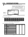
Customizing the Sub Display................................................... 68
7.5.7.
Graphic Display ....................................................................... 69
7.5.8.
Total Operation........................................................................ 70
7.5.9.
Undoing the Total Operation ................................................... 70
7.5.10.
Clearing (Deleting) the Totaled Data ....................................... 70
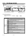
7.5.11.
Error Message and Alarm ....................................................... 71
7.5.12.
Graphic Status Indicator.......................................................... 73
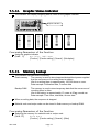
7.5.13.
Memory Backup ...................................................................... 73
8.
Interface........................................................................................... 74
8.1.
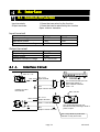
Control I/O Function .................................................................... 74
8.1.1.
Interface Circuit ....................................................................... 74
8.1.2.
Timing Chart............................................................................ 75
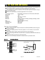
8.2.
Built-in RS-485 Interface ............................................................. 76
8.2.1.
Connection .............................................................................. 76
8.2.2.
Settings of Parameters............................................................ 77
8.2.3.
Timing Chart............................................................................ 78
8.2.4.
General Data Format............................................................... 79
8.2.5.
A&D Data Format .................................................................... 80
8.2.6.
Address ................................................................................... 80
8.2.7.
Command List ......................................................................... 81
Page 2
AD-4402
8.3.
8.3.1.
8.3.2.
8.3.3.
8.4.
8.5.
8.6.
8.7.
8.8.
8.9.
9.
Built-in Current Loop Output ........................................................ 84
Connection .............................................................................. 84
Communication Modes............................................................ 84
Data Format ............................................................................ 85
BCD Output of Option OP-01 ...................................................... 85
Relay Output of Option OP-02..................................................... 89
RS-422/485 Interface of Option OP-03........................................ 90
RS-232C Interface of Option OP-04 ............................................ 93
Parallel I/O of Option OP-05 ........................................................ 94
Analog Output of Option OP-07................................................... 95
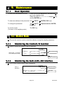
Maintenance .................................................................................... 96
9.1.1.
Basic Operation....................................................................... 96
9.2.
Monitor Mode............................................................................... 96
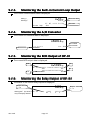
9.2.1.
Monitoring the Control I/O Function......................................... 96
9.2.2.
Monitoring the Built-in RS-485 Interface.................................. 96
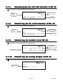
9.2.3.
Monitoring the Built-in Current Loop Output ............................ 97
9.2.4.
Monitoring the A/D Converter .................................................. 97
9.2.5.
Monitoring the BCD Output of OP-01 ...................................... 97
9.2.6.
Monitoring the Relay Output of OP-02 .................................... 97
9.2.7.
Monitoring the RS-422/485 Interface of OP-03 ........................... 98
9.2.8.
Monitoring the RS-232C Interface of OP-04............................ 98
9.2.9.
Monitoring the Parallel I/O of OP-05........................................ 98
9.2.10.
Monitoring the Analog Output of OP-07 .................................. 98
9.3.
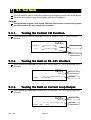
Test Mode.................................................................................... 99
9.3.1.
Testing the Control I/O Function.............................................. 99
9.3.2.
Testing the Built-in RS-485 Interface....................................... 99
9.3.3.
Testing the Built-in Current Loop Output ................................. 99
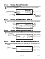
9.3.4.
Testing the A/D Converter ..................................................... 100
9.3.5.
Testing the BCD Output of OP-01 ......................................... 100
9.3.6.
Testing the Relay Output of OP-02 ....................................... 100
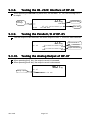
9.3.7.
Testing the RS-422/485 Interface of OP-03 .......................... 100
9.3.8.
Testing the RS-232C Interface of OP-04............................... 101
9.3.9.
Testing the Parallel I/O of OP-05........................................... 101
9.3.10.
Testing the Analog Output of OP-07 ..................................... 101
9.4.
Initializing Parameters ............................................................... 102
9.5.
Remote Operation ..................................................................... 104
10.
Function List .................................................................................. 105
10.1.1.
Operation Keys...................................................................... 105
10.1.2.
Outline of the Function List.................................................... 106
10.2.
Referring Parameters ................................................................ 107
10.3.
Parameter Settings.................................................................... 107
10.4.
Parameter List ........................................................................... 108
11.
11.1.
11.2.
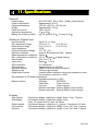
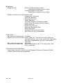
Specifications................................................................................. 134
Dimensions................................................................................ 137
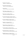
Accessories ............................................................................... 137
12.
12.1.
12.2.
12.3.
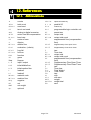
References .................................................................................... 138
Abbreviations............................................................................. 138
ASCII Code for AD-4402 ........................................................... 139
Index.......................................................................................... 140
AD-4402
Page 3
1. Compliance
1.1.1. Compliance with FCC rules
Please note that this equipment generates, uses and can radiate radio frequency
energy. This equipment has been tested and has been found to comply with the limits
of a Class A computing device pursuant to Subpart J of Part 15 of FCC rules. These
rules are designed to provide reasonable protection against interference when this
equipment is operated in a commercial environment. If this unit is operated in a
residential area it may cause some interference and under these circumstances the
user would be required to take, at his own expense, whatever measures are
necessary to eliminate the interference.
(FCC = Federal Communications Commission in the U.S.A.)
1.1.2.
Compliance with European Directives
Directives
This appliance complies with the statutory EMC (Electromagnetic Compatibility)
directive 89/336/EEC and the Low Voltage Directive 73/23/EEC for safety of electrical
equipment designed for certain voltages.
Note: The displayed value may be adversely affected under extreme electromagnetic
influences.
Page 4
AD-4402
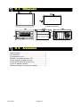
2. Outline and Features
Features
The AD-4402 is a multi-function weighing indicator for batch weighing and filling
weighing. This indicator has control I/O for weighing sequence and options.
Large display
This indicator has a blue vacuum fluorescent display (VFD).
The character height of the main display is 18 mm.
Current weighing data, material names, setpoints (comparison references) and total
data are displayed at the same time.
Operation guidance
Messages that assist current operation are displayed on the front panel and anyone
could operate the indicator without instruction manuals.
Full weighing sequences
The AD-4402 can combine multiple materials and is equipped with the recipe function.
Equipped with a filling nozzle and agitation sequence.
Using the forecast control function, the flow control can be performed that is
equivalent to A/D conversion of 1000 times per second.
RS-485 interface
32 indicators can be connected to a programmable controller or a personal computer.
These protocols are according to public formats.
Options
There are options of AC 250 V direct drive relay, serial interface, parallel interface,
analog output and etc.
There are options of CC-Link, DeviceNet and PROFIBUS.
There are three expansion slots for options.
Check mode during operation
The monitor mode can confirm system status during operation.
The test mode can test the Input / Output interface.
Even if there is no monitor instrument, the interface can be confirmed.
Recipes and raw material data stored in the indicator
The recipe is described as combination of material codes and weights.
The material code is described as the weighing sequence parameters for a raw material.
Water-resistant panel
The classification code of the front panel is equivalent to IP-65 of IEC 529 using the
accessory rubber packing. The "IP-65" code is explained as follows:
IP:
International Protection.
6:
Against ingress of solid foreign objects.
Dust-tight. No ingress of dust.
5:
Against ingress of water with harmful effects.
Protected against water jets (no powerful jets). Water projected in jets against
the enclosure from any direction shall have no harmful effects.
AD-4402
Page 5
2.1. Precaution
Before use, confirm the following articles for safe operation.
Grounding the indicator
Ground the indicator. The earth terminal is on the rear panel.
Separate this earth ground line from others, like ground line of a motor, inverter or a
power source. Unless the indicator is grounded, it may cause the operator to receive
an electric shock, cause operation error or catch fire
Use adequate power cord
Confirm the AC voltage and current of the power cord. If the voltage range of the cord
is lower than the power line voltage, it may cause of a leak or catching fire. Use
compression terminals to connect the power cord to the rear panel terminals.
Fuse
The fuse is installed to prevent the indicator from catching fire.
The indicator has equipped many safety circuits. Therefore, the fuse is not broken in
normal operation. If the fuse is broken, do not replace the fuse and contact your local
or A&D dealer. This trouble may cause of an electric discharge of thunder.
Splashing water
The indicator is not water-resistant. When the indicator is mounted to a panel with the
accessory rubber seal, the front panel is equivalent to IP-65.
Flammable gas
Do not install the indicator in any flammable gas.
Heat radiation of the indicator
Space out instruments to radiate heat sufficiently.
Removing the cover
Remove the power cord terminals from the power source before removing the cover
to avoid receiving an electric shock.
Do not touch the internal circuit within 10 seconds after turning off the indicator to
avoid receiving an electric shock.
Page 6
AD-4402
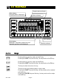
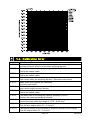
2.2. Front Panel
Graphic status indicator
Main display
Weighing data is displayed.
Status indicator
Unit indicator
Sub-display
Materials, Total data, parameters and
operation guidance are displayed.
2.2.1.
Standby indicator
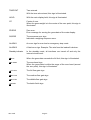
Keys
Pressing this key, the key works as the F1 key.
Pressing the SHIFT key and this key, the key works as the F3 key.
Pressing this key, the key works as the F2 key.
Pressing the SHIFT key and this key, the key works as the F4 key.
The key to select a function of a key.
The key to open the material code or recipe code.
Pressing the SHIFT key and this key, the key works as the material
code edit key.
Pressing the ENTER key and this key, the key works as the recipe
code edit key.
AD-4402
Page 7
The key to move the cursor or scroll the function number.
Press and hold the SHIFT key and press the key to decrease the
code number.
The key to select alphabetical keys, upper keys, lower keys or
numerical keys.
Alphanumeric keys.
The escape key. Pressing and holding the key more than three seconds
in normal weighing mode, the display is turned off (standby mode).
The ESC key is used to undo the last key action and to return to the
last mode.
The ENTER key for parameter settings.
The key to turn on the display.
Pressing this key and the key, the key works as the menu key.
The key to select net or gross
The tare key. The key is used to display the net value after that tare
weight is subtracted from the gross weighing.
The zero key. To zero the current weighing display.
2.2.2.
Symbols
Main display
Gross or net is displayed.
Sub display
Code numbers, operation guidance, graph, setpoint and others are
displayed selectively.
Unit indicator
The indicator that is displayed when the weighing unit is selected in
the calibration mode. Refer to section "5. Calibration".
Status indicator
The current weighing status is displayed.
Graphic status
indicator
The current weighing situation is displayed with symbols.
The classification number is displayed, when an error occurred or
an alarm is indicated.
STABLE
With this sign illuminated, the current weighing display is stable.
GROSS
The main display is the gross data, when this sign is illuminated.
NET
The main display is the net data, when this sign is illuminated.
Page 8
AD-4402
TARE ENT
Tare entered.
With the tare value stored, this sign is illuminated.
HOLD
With the main display held, this sign is illuminated.
CZ
Center of zero.
When the gross weight is in the center of the zero point, this sign is
illuminated.
ZR.ERR
Zero error.
Error message for zeroing the gross data of the main display.
SQ.ERR
The sequence error sign.
Indicates a weighing sequence error.
ALARM 1
An error sign for over load or emergency stop mode.
ALARM 2
A fatal error sign. Example: The wire from the loadcell is broken.
Standby indicator
In the standby mode, all interfaces are turned off and only the
internal circuits work.
FULL
When the gross data exceeds the full limit, this sign is illuminated.
Z. BAND
The zero band sign.
When the gross data is within the range of the zero band (around
the zero point), this sign is illuminated.
F.FLOW
The full flow gate sign.
M.FLOW
The medium flow gate sign.
D.FLOW
The dribble flow gate sign.
FINISH
The batch finish sign.
AD-4402
Page 9
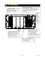
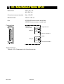
2.3. Rear Panel
Loadcell terminal.
Eight 350Ω loadcells can be
connected in parallel.
Built-in RS-485 terminal.
The possibility: to read weighing data,
write parameters, connect 32 units of the
indicator using with the multi-drop
connection.
Main
power
switch
Power
cord
terminal
AC85V
~ 250V
Control I/O to connect to
external control units.
11 input terminals,
11 output terminals,
An input common terminal
An output common terminal
Option slot to connect
maximum three options.
Example: BCD output,
Relay output, Analog
output and field bus.
Built-in current loop output
Use to connect A&D
external monitor
Page 10
AD-4402
3. Installation
Caution
Remove the power cord before installing the indicator and an option.
Turn off peripheral devices before installing it.
Insert the options before installing the indicator.
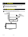
3.1. Mounting Indicator
The indicator can be mounted on a panel using the slide rail.
If the accessory packing rubber is used, the front panel is equivalent to IP-65 of IEC 529.
AD-4402
Page 11
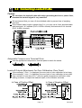
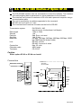
3.2. Connecting Loadcell
Loadcell Cable
Caution
Do not share the loadcell cable with noise-generating devices or power lines,
beacuse the loadcell signal is very sensitive.
We recommend that you use a 6 wire shielded cable to prevent loss of weighing
precision.
If the loadcell cable length is shorter than 5 m, you may use a 4 wire shielded cable
with terminals 1 & 2 shorted (EXC+ & SEN+ shorted) and terminals 3 & 4 shorted
(EXC- & SEN- shorted).
Adaptable Compression Terminal Parts
Use the appropriate compression terminal parts to attach the cables.
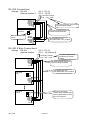
Loadcell Output Adjustment for Zero Calibration (Zero Point)
If the message "CERR2" is displayed, the zero point of zero calibration is too large.
If the message "CERR3" is displayed, the zero point of zero calibration is too small.
Use a resistor of more than 50 kΩ with low (good) temperature coefficient, when
adding a resistor, to adjust the loadcell output, to the indicator terminals.
In Case of Positive Offset
In Case of Negative Offset
Page 12
AD-4402
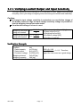
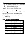
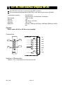
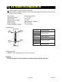
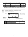
3.2.1. Verifying Loadcell Output and Input Sensitivity
The input sensitivity of the indicator is 0.3µV/division or more. Adapt to the following
inequality, when you design a weighing instrument using the indicator and loadcell(s).
Caution
A change in input voltage sensitivity is equivalent to a one division change of
the display. Select as large an input voltage sensitivity voltage as possible so
that the weighing interval becomes stable.
Consider the leverage if a lever is used.
E ∗B ∗D
Weighing instrument
0 .3 ≤
using one loadcell.
A
E ∗B ∗D
Weighing instrument
0 .3 ≤
using multi-loadcell
A ∗N
A: Rated capacity of loadcell [kg]
B: Rated output [mV/V]
D: Weighing interval [kg]
E: Excitation voltage [mV]
N: Number of loadcells
Verification Example
Design:
Loadcell
Rated capacity
Rated output
Excitation voltage
Weighing interval
Weighing capacity
AD-4402
N=1
A=750 [kg]
B=3 [mV/V]
E=5000 [mV]
D=0.05 [kg]
300 [kg]
Page 13
5000 ∗ 3 ∗ 0.05
= 1 ≥ 0.3 . Therefore,
750
regard the instrument as a good design.
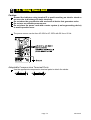
3.3. Wiring Power Cord
Caution
Gorund the indicator using terminal E to avoid receiving an electric shock or
an error due to discharge of static electricity.
Do not share the ground wire with an electrical device that generates noise.
Do not use an unstable power source.
Do not share the power cord with a moter system (a noise-generating device)
to avoid operation error.
The power source can be from AC 85V to AC 250V with 50 Hz or 60 Hz.
Adaptable Compression Terminal Parts
Use the appropriate compression terminal parts to attach the cables.
Page 14
AD-4402
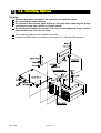
3.4. Installing Options
Caution
Remove the power cord before the operation to install an option.
Do not install the same options.
Do not touch the internal parts within ten seconds after removing the power
cord because you may receive an electric shock.
Do not forget to tighten the screws. If a screw is not tightened, it may cause a
short circuit or an error due to noise.
Three option boards can be installed in the slots.
Initialize the RAM data in accordance with section 9.4. Initializing Parameters.
AD-4402
Page 15
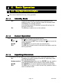
4. Basic Operation
4.1. Key Operation Exam
Examples
ples
This section describes the way of key operation.
4.1.1.
OFF
ON
4.1.2.
Standby Mode
Press and hold the OFF key about three seconds in the
weighing mode. Then the indicator enters the standby mode
and displays the standby indicator.
In the standby mode, All interface is turned off and only the
internal circuits work.
The ON key is used to turn on the indicator.
Cursor Operation
There is a cursor on a segment (an item) that is turned on and off.
The key is used to move the cursor forward.
SHIFT +
Press and hold the SHIFT key and press the key to move the
cursor backward.
ENTER
The ENTER key is used to enter the selected item.
ESC
The ESC key is used to return to the last mode and to undo the
last key operation.
4.1.3.
Inputting Characters
A character can be input in a current segment (an item) in the appropriate mode.
A/a
The A/a key is used to change numerical key, upper keys, lower
keys and alphabetical key.
Alphanumerical The alphanumerical keys and the ENTER key are used to
enter the parameters and to select a code number directly.
ENTER
The ENTER key is used to specify the alphanumerical data.
ESC
The ESC key is used to undo the last key operation and to
return to the last mode.
Page 16
AD-4402
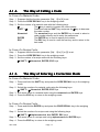
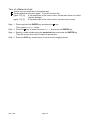
4.1.4.
The Way of C
Calling
alling a Code
In Case of a Material Code:
Step 1 Suppose that the function parameter [5qf- 8] to [0] is set.
Step 2 Press the CODE RECALL key in the weighing mode.
Step 3 Set the number of a material code with the following keys:
The key is used to increase the code number.
SHIFT +
Press and hold the SHIFT key and press the key to decrease
the code number.
Numerical
The numerical keys and the ENTER key is used to select a
code number directly and to enter the parameters.
ENTER
The ENTER key is used to specify the number.
ESC
The ESC key is used to undo the last key and to return to the
last mode.
In Case of a Recipe Code:
Step 1 Suppose that the function parameter [5qf- 8] to [1] or [2] is set.
Step 2 Press the CODE RECALL key in the weighing mode.
Step 3 Set the number of a recipe code with the following keys:
, SHIFT + , Numerical, ENTER, ESC keys
4.1.5.
The Way of Entering a Correction Mode
In Case of a Material Code:
Step 1 Press and hold the SHIFT key and press the CODE RECALL key in the weighing
mode.
Step 2 Select the number of a material code using the following keys:
, SHIFT + , Numerical, ENTER, ESC keys
Step 3 Edit some items of a material code using the numerical and ENTER keys.
Step 4 Press the ESC key to return to the weighing mode.
In Case of a Recipe Code:
Step 1 Press and hold the ENTER key and press the CODE RECALL key in the weighing
mode.
Step 2 Select the number of a recipe code using the following keys:
, SHIFT + , Alphanumerical, A/a, ENTER, ESC keys
Step 3 Edit some items of a recipe code using alphanumericand ENTER keys.
Step 4 Press the ESC key to return to the weighing mode.
AD-4402
Page 17
4.1.6.
The Way of Entering The Menu
Step 1 Press and hold the ENTER key and press the key in the weighing mode.
Then the first layer of menu is displayed.
Step 2 Use the following keys in the menu :
, SHIFT, Alphanumerical, A/a , ENTER, ESC keys
Step 3 Press the ESC key several times to return to weighing mode.
Page 18
AD-4402
4.2. Status Chart (Mode map)
map)
AD-4402
Page 19
5. Calibration
The indicator, which is connected to a loadcell unit, can weigh the "weight" value on
the loadcell pan and display its "mass" value. The calibration function is used to
adjust the displayed value so that the weighing system can weigh correctly.
There are two ways of calibration. The "actual load calibration" uses a rated mass
and zero output from the loadcell. The "digital span" inputs arbitrary values
(calculated by hand). These methods are selected in the calibration procedure.
There is a compensation function of the "gravity acceleration correction".
This function is used, when a calibrated weighing system is moved to another place.
The calibration parameters are stored in the indicator without any power supply.
Common Calibration Items
Unit
Decimal point
Minimum division
Weighing capacity
The "g", "kg" and "t" or "lb" can be selected (lb: USA only).
The decimal point can be selected from "not used" to "four
decimal places".
The minimum division of the weighing display.
The maximum display of the weighing display.
Items for the "Actual Load Calibration"
Common items
Zero point adjustment
Span adjustment
Items for "Digital Span"
Common items
Zero point output
Rated capacity
Sensitivity
Unit, decimal point, minimum division and weighing capacity
A zero point output is used from the loadcell unit.
Rated mass is place on the weighing pan and is weighed.
The sensitivity is adjusted. This sensitivity is the same as "
sensitivity " of digital span.
Unit, decimal point, minimum division and weighing capacity
The numerical data is input as the zero point output of the
loadcell unit.
The rated capacity of the loadcell is input.
The sensitivity of the loadcell is input.
Caution
When the CAL switch on the A/D board is "DISABLE", no calibration can be
performed.
Do not perform any calibration during a weighing sequence operation.
Entering calibration mode during a weighing sequence operation, the weighing
sequence operation is terminated. Calibrate the weighing system only when
the weighing sequence operation has stopped
The accuracy of the "Digital Span (Calibration without Mass)" is 1/1000.
Do not use a "loadcell summing box", when the "digital span" is performed.
It is necessary that the loadcell sensitivity is exactly known, if the "digital
span" is used.
Page 20
AD-4402
5.1. Actual Load Calibration (using a Mass)
ESC key
ENTER key
If you want to return to the weighing mode during the
calibration mode, press the ESC key anytime. It is
effective until the last displayed parameter.
Example: zero adjustment only, etc.
When the key is pressed, the procedure stores the
current parameter and proceeds to the next step.
Step 1 Press and hold the ENTER key and press the key to display the
menu in the weighing mode.
Step 2 Press the key twice to select the menu CAL.
Press the ENTER key to enter the calibration mode.
Step 3 Press the ENTER key to enter the menu CAL.
Step 4 Select a unit using the numerical keys and press the ENTER key
to store it.
Step 5 Select a decimal point using the numerical keys and press the
ENTER key to store it.
Step 6 Select a minimum division using the numerical keys and press the
ENTER key to store it.
Step 7 Select a weighing capcity using the numerical keys and press the
ENTER key to store it.
Step 8 Perform the zero point adjustment.
Place nothing on the weighing pan and press the ENTER key to
store it after the STABLE indicator is displayed.
Whether the STABLE indicator is displayed or not, if you want to
store it, wait for ten seconds and press the ENTER key.
Step 9 If the F1 key is pressed, it will branch out to the digital span.
Step 10 Specify a total mass value to place on the weighing pan using the
numerical keys and press the ENTER key to store it.
Step 11 Place the specifyed mass on the weighing pan and press the
ENTER key to store it after the STABLE indicator is displayed.
Whether the STABLE indicator is displayed or not, if you want to
store it, wait for ten seconds and press the ENTER key.
Step 12 Press the ESC key to return the weighing mode.
AD-4402
Page 21
5.2. Digital Span (Calibration without a Mass)
ESC key
ENTER key
If you want to return to the weighing mode during the
calibration mode, press the ESC key anytime. It is
effective until the last displayed parameter.
Example: zero adjustment only, etc.
When the key is pressed, the procedure stores the
current parameter and proceeds to the next step.
Step 1 Press and hold the ENTER key and press the key to display the
menu in the weighing mode.
Step 2 Press the key twice to select the menu CAL.
Press the ENTER key to enter the calibration mode.
Step 3 Press the ENTER key to enter the menu CAL.
Step 4 Select a unit using the numerical keys and press the ENTER key
to store it.
Step 5 Select a decimal point using the numerical keys and press the
ENTER key to store it.
Step 6 Select a minimum division using the numerical keys and press the
ENTER key to store it.
Step 7 Select a weighing capcity using the numerical keys and press the
ENTER key to store it.
Step 8 Press the F1 key to proceed to the next step.
Step 9 Store the zero point value.
If you need a new the zero point value, input it using the numerical
keys and press the ENTER key to store it.
If you do not need a new the zero point value, press the ENTER
key to preceed the next step.
Step 10 Input the rated capacity of a loadcell using the numerical keys and
press the ENTER key to store it.
Step 11 Input the sensitivity of the loadcell in the unit of mV/V using the
numerical keys and press the ENTER key to store it.
Step 12 Press the ESC key to return the weighing mode.
Advise The digital span can be used for trimming of the actual load calibration using a mass.
Page 22
AD-4402
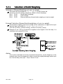
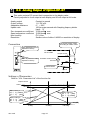
5.3. Gravity Acceleration Correction
The function compensates for weighing error due to the difference of gravity
acceleration.
G1
The place where the weighing system is calibrated.
G2
The place where the weighing system is used.
ESC key
ENTER key
If you want to return to the weighing mode during the
calibration mode, press the ESC key anytime.
When the key is pressed, the procedure stores a current
parameter and proceeds to next step.
Step 1 Press and hold the ENTER key and press the key to display the menu in the
weighing mode.
Step 2 Press the key twice to select the menu CAL. Press the ENTER key to enter the
calibration mode.
Step 3 Select the menu G with the key. Press the ENTER key to enter it.
Step 4 Input the gravity acceleration at G1 using the numerical keys and press the
ENTER key to store it.
Step 4 Input the gravity acceleration at G2 using the numerical keys and press the
ENTER key to store it.
Step 5 Press the ESC key to return the weighing mode.
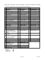
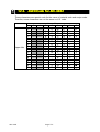
5.3.1.
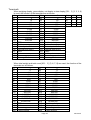
Gravity Acceleration Reference
Amsterdam
Athens
Auckland NZ
Bangkok
Birmingham
Brussels
Buenos Aires
Calcutta
Chicago
Copenhagen
Cyprus
Djakarta
Frankfurt
Glasgow
Havana
Helsinki
Kuwait
Lisbon
London (Greenwich)
Los Angeles
Madrid
AD-4402
9.813
9.800
9.799
9.783
9.813
9.811
9.797
9.788
9.803
9.815
9.797
9.781
9.810
9.816
9.788
9.819
9.793
9.801
9.812
9.796
9.800
m/s2
m/s2
m/s2
m/s2
m/s2
m/s2
m/s2
m/s2
m/s2
m/s2
m/s2
m/s2
m/s2
m/s2
m/s2
m/s2
m/s2
m/s2
m/s2
m/s2
m/s2
Manila
Melbourne
Mexico City
Milan
New York
Oslo
Ottawa
Paris
Rio de Janeiro
Rome
San Francisco
Singapore
Stockholm
Sydney
Tainan
Taipei
Tokyo
Vancouver, BC
Washington DC
Wellington NZ
Zurich
Page 23
9.784
9.800
9.779
9.806
9.802
9.819
9.806
9.809
9.788
9.803
9.800
9.781
9.818
9.797
9.788
9.790
9.798
9.809
9.801
9.803
9.807
m/s2
m/s2
m/s2
m/s2
m/s2
m/s2
m/s2
m/s2
m/s2
m/s2
m/s2
m/s2
m/s2
m/s2
m/s2
m/s2
m/s2
m/s2
m/s2
m/s2
m/s2
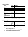
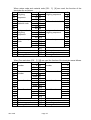
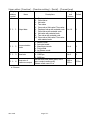
5.4. Calibration Error
Error Code Situation and Treatment
CERR1
Resolution (Weighing capacity / minimum division) exceeds the limitation.
Increase minimum division or decrease weighing capacity.
CERR2
The initial load (no load output) is larger than 2mV/V.
Check the loadcell cable.
CERR3
Negative loadcell output value.
Check the loadcell cable.
CERR4
Mass value exceeds the weighing capacity.
Use a mass within the weighing capacity. (Decrease mass value)
CERR5
Mass value is too light for the calibration.
Increase mass value.
CERR6
The loadcell output to be equivalent to the minimum division is too small.
Use a more rough minimum division.
CERR7
The polarity of the loadcell output is reversed.
Check the loadcell cable.
CERR8
The mass value of the weighing capacity exceeds 3.2 mV/V.
Confirm the mass and weighing capacity.
CERR9
Gravity acceleration is out of range.
Correct the value within the range of 9.770 ~ 9.835 m/s2.
CERR10 Zero output of the loadcell unit is out of range.
Trim the zero output within 0.0 ~ 2.0 mV/V.
CERR11 The loadcell output to be equivalent to minimum division is out of range.
Trim the output within 0.0 ~ 3.2 mV/V.
Page 24
AD-4402
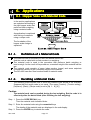
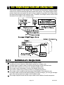
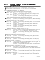
6. Applications
6.1. Hopper Scale with Material Code
In the section, applications
are explained according to
the right hopper scale that
performs batch weighing
using a material code.
An application is explained
with mixing of materials
using a recipe code.
The foundation of the
hopper scale design is
explained.
6.1.1.
Definition of a Material Code
The material code is necessary to store the details before use.
And the code is called with a code number in a weighing.
The material code is used in the procedure that performs batch weighing or
loss-in-weigh. As the result of the procedure, a constant weight of the material can be
got.
The material code consists of some index number (name) and some setpoints
(comparison values) to get a constant weight of the material.
The AD-4402 can store one hundred kinds of material codes.
6.1.2.
Recalling a M
Material
aterial Code
The following steps explain how to recall the material code stored in the indicator.
Suppose that the recipe code is not used. (The menu [Function] - [Function setting] [Sequence] - [Basic] - [Recipe mode] is set to [5q f- 8] [0] )
Caution
The material code can be recalled during the last weighing. But the code is in
effect only after the batch finish (after finishing the last weighing).
Step 1 Press the CODE RECALL key.
Then the material code indicator blinks.
Step 2 Enter the material code using the numerical keys
The details of the material code are displayed in the sub-display.
Step 3 Press the ENTER key to decide the code.
AD-4402
Page 25
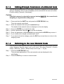
6.1.3.
Editing Principle Parameters of a Material Code
You can edit the parameters of final weight, free fall etc. displayed on the sub-display
during a weighing. Items of the sub-display can be selected at the menu [Function] [Function setting] - [General] - [Sub-display].
Caution
If the flash memory is selected for memory backup (0tHf
0tHf0tHf-11),
11 the current batch
weighting is stopped while editing them.
Step 1 Press and hold the SHIFT key and press the CODE RECALL key.
Then the material code blinks.
Step 2 Enter the material code using the numerical keys
The details of the material code are displayed on the sub-display.
Step 3 Press the ENTER key to decide the code.
Step 4 Select a parameter using the key on the sub-display.
Step 5 Enter the parameter using numerical keys and press the ENTER key to store it.
Step 6 If you continue the change, proceed step 4 and 5.
Step 7 If you want to finish the change, press the ESC key several times to return to the
weighing mode.
6.1.4.
Referring
Referring to the next Material Code
You can refer to next material code in the sequential mode that uses multiple material
codes. Suppose that the recipe code is not used. (The menu [Function] - [Function
setting] - [Sequence] - [Basic] - [Recipe mode] is set to [5q f- 8] [0])
Step 1 Press the CODE RECALL key.
Then principle parameters of the next material code are displayed in the
sub-display.
Step 2 Press the ESC key to return to current mode.
Page 26
AD-4402
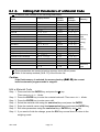
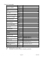
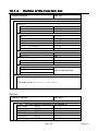
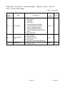
6.1.5.
Editing Full Parameters of a Material Code
A material code consists of the following parameters.
Display Name
Display
Name
Symbol
Display
Example
Memory
Material Code
Code
11
Material name
Mat Name
Material Hopper No.
Mat Hopper
Hopper
1
Final
Final
Final
10.00 kg
Free Fall
Free Fall
FFall
0.01 kg
Preliminary
Preliminary
Plm
1.00 kg
Backed up
Optional Preliminary
OP.Preliminary
OPPlm
2.00 kg
RAM
Over
Over
Over
0.10 kg
( factory
Under
Undr
Undr
0.10 kg
setting)
Zero Band
Zero Band
0Band
0.02 kg
or
Full
Full
Full
0.05 kg
flash
Tare
Tare
Tare
5.00 kg
memory
Supplementary Flow Open Timer
SF open timer
SFOT
0.00 s
Supplementary Flow Close Timer
SF close
SFCT
0.0 s
Automatic Free Fall Range
AFFC range
AFFC
0.00 kg
Initial Dribble Flow
Initial DF
IDF
0.00 kg
Initial Medium Flow
Initial MF
IMF
0.00 kg
Total Weight
Tot
Tot
10.00 kg
Backed up
Total Count
Tot#
Tot#
1
RAM
Code
grain
These parameters are stored in backup memory even without power.
Refer to the backup method [0tHf-11] of the function list.
Caution
If the flash memory is selected for memory backup [0tHf
0tHf0tHf-11],
11 the current
built-in automatic program mode is stopped.
Edit a Material Code
Step 1 Press and hold the ENTER key and press the
Then menu MatEdit blinks.
Step
Step
Step
Step
Step
2
3
4
5
5
key.
Press the ENTER key to enter the material code edit. Then menu Edit blinks.
Press the ENTER key to enter menu edit.
Select the material code using the numerical keys and press the ENTER.
Enter the material name using the alpanumerical keys and press the ENTER key.
Edit other parameters using the numerical keys, ENTER key and key.
Step 6 If you want to finish the change, press the ESC key several times to return to the
weighing mode.
AD-4402
Page 27
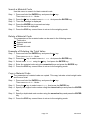
Search a Material Code
Use this menu to search for blank material code.
Step 1 Press and hold the ENTER key and press the
key.
Then menu MatEdit blinks.
Step 2 Press the
key to select menu Search. And press the ENTER key.
Step 3 Then the message is displayed.
Step 4 Press the ENTER key to prceed next step.
Then the result is displayed.
Step 5 Press the ESC key several times to return to the weighing mode.
Delete a Material Code
The parameters of the material code can be reset in the following menu.
Total value
Setpoint and total
All total
All material code
Example of Deleting the Total Value
Step 1 Press and hold the ENTER key and press the
key.
Then menu MatEdit blinks.
Step 2 Press the
key to select menu Delete. And press the ENTER key.
Step 3 Select menu Total using the
key. And press the ENTER key.
Step 4 Enter the material code using the numerical keys and press the ENTER key.
Step 5 Press the ESC key several times to return to the weighing mode.
Copy a Material Code
The parameters of material code are copied. This copy includes a total weight value
and times of total.
Step 1 Press and hold the ENTER key and press the
key.
Then menu MatEdit blinks.
Step 2 Press the
key to select menu Copy. And press the ENTER key.
Step 4 Specify the original code number using the numerical keys and press the ENTER
key.
Step 5 Specify a duplicated code number using the numerical keys and press the ENTER
key.
Step 6 Press the ESC key several times to return to the weighing mode.
Page 28
AD-4402
Tare of a Material Code
Use to copy a current tare to the preset tare.
Set the preset tare function [genf-12 ] of the function list.
[genf-12] [0]
If the preset tare of the code is zero, the last tare value is in effect.
(factory settings)
[genf-12] [1]
If the preset tare of the code is zero, the tare value is reset.
Step 1 Press and hold the ENTER key and press the
key.
Then menu MatEdit blinks.
Step 2 Press the
key to select the menu Tare. And press the ENTER key.
Step 4 Specify a code number using the numerical keys and press the ENTER key.
Then the current tare value is copied to preset tare.
Step 5 Press the ESC key several times to return to the weighing mode.
AD-4402
Page 29
6.2. Simple Hopper Scale with a Recipe Code
This section explains for the recipe code. The recipe code is used on a simple hopper
scale to mix several materials that have preset final values. "The simple hopper scale"
means that it does not control the ratio or the a weight of ingredient, but simply totals
the preset final weight of the material code. Therefore, the recipe code is used to total
the preset final weight of the material code.
6.2.1.
Definition of a Recipe Code
A recipe code consists of multiple preset material codes.
A maximum of ten material codes can be stored in a recipe code.
A recipe code is used in order to total the final weight of the material code.
The AD-4402 indicator can store one hundred recipe codes.
The recipe code is necessary, to store the details before use.
The code is called using a code number in a weighing sequence.
The recipe code is used to total the preset final weight of the material code.
If a recipe code is used in the batch weighing (or loss-in-weigh), you can get a weight
that is the total preset final weight of the material code.
The recipe sequence that uses a recipe code is also called a formula sequence.
Page 30
AD-4402
6.2.2.
Using a Recipe Code
Set the menu [Function] - [Function setting] - [Sequence] - [Basic] - [Recipe mode] to
sequential mode ( [5q f- 8] to [1] or [2] ), when the recipe code is used.
[5q f- 8] [1] Semi-automatic mixing sequence
[5q f- 8] [2] Automatic mixing sequence
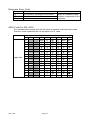
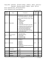
6.2.3.
Construction of a Recipe Code
The AD-4402 indicator can store one hundred recipe codes.
A recipe code can store a maximum of ten material codes in the order of
accumulating them.
These parameters are stored in backup memory even without power.
Refer to the backup method [0tHf-11] of the function list.
Caution
If the flash memory is selected for memory backup [0tHf
0tHf0tHf-11],
11 the current
built-in automatic program mode is stopped.
Name
Display Symbol & Example
Memory
Recipe code
rCode
Backed up RAM
Recipe name
Blend coffee
( factory setting)
Material codes of maximum ten codes.
It is stored in order to accumlate them.
Code 1
Total Weight for a recipe code
Total Counts for a recipe code
6.2.4.
or
flash memory
RTot
10.00
RTot#
Backed up RAM
1000
Recalling a Recipe Code
The following steps are the explanation of how to recall the recipe code stored in the
indicator. Suppose that the recipe code is used (The menu [Function] - [Function setting]
- [Sequence] - [Basic] - [Recipe mode] is set to [5q f- 8] [1] or [2]). .
Caution
The code can be recalled during the last weighing. But the code is in effect
only after the batch finish (after finishing the last weighing).
Step 1 Press the CODE RECALL key.
Then the recipe code blinks.
Step 2 Enter the material code using the numerical keys
The details of the recipe code are displayed in the sub-display.
Step 3 Press the ENTER key to decide the code.
AD-4402
Page 31
6.2.5.
Arranging Material Code in a Recipe Code
The way of arranging the material code described in a recipe code.
Step 1 Press and hold the ENTER key and press the CODE RECALL key.
Step 2 Select a recipe code number using the numerical keys and press the ENTER key.
Then the first material code blinks.
Step 3 Select a material code using the following keys.
key, the numerical keys and the SHIFT key
Step 4 Press the ENTER key to store it. Then the next code blinks.
Step 5 Continue step 3 and 4 until the last material code is stored.
Step 6 Press the ESC key several times to return to the weighing mode.
6.2.6.
Editing Full Parameters of a Recipe Code
All parameters of the recipe code can be edited in this menu.
Edit the Name of a Recipe Code
Step 1 Press and hold the ENTER key and press the
key.
Press the
key. Then the menu RecipeEDIT blinks.
Step
Step
Step
Step
Step
2
3
4
5
6
Press the ENTER key to edit the recipe code. Then the menu edit blinks.
Press the ENTER key to enter menu edit.
Select a recipe code using the numerical keys and press the ENTER key.
Name the recipe code using the alpanumerical keys and press the ENTER key.
If you have finished the change, press the ESC key several times to return to the
weighing mode.
Search of a Recipe Code
Use this menu to search for blank material code.
Step 1 Press and hold the ENTER key and press the
key.
Press the
key. Then the menu RecipeEDIT blinks.
Step 2 Press the
key to select the menu Search. And press the ENTER key.
Step 3 Then the message is displayed.
Step 4 Press the ENTER key to prceed next step.
Then the results are displayed.
Step 5 Press the ESC key to return several times to weighing mode.
Delete of Recipe Code
The parameters of the recipe code can be reset in the following menu.
Page 32
AD-4402
Total value
Recipe total value
All total values
All Recipes
Example of Deleting a Total Value
Step 1 Press and hold the ENTER key and press the
key.
Then the menu RecipeEDIT blinks.
Step 2 Press the
key to select the menu Delete. And press the ENTER key.
key.
Step 3 Select the menu Total using the
And press the ENTER key.
Step 4 Enter the recipe code using the numerical keys and press the ENTER key.
Step 5 Press the ESC key to return several times to weighing mode.
Copying a Recipe Code
The parameters of a recipe code are copied. This copy includes a total weight value
and times of total.
Set the preset tare function [ genf-12 ] of the function list.
[genf-12] [0]
If the preset tare of the code is zero, the last tare value is in effect.
(factory settings)
[genf-12] [1]
If the preset tare of the code is zero, the tare value is reset.
Step 1 Press and hold the ENTER key and press the
key.
Then the menu RecipeEDIT blinks.
Step 2 Press the
key to select the menu Copy. And press the ENTER key.
Step 4 Specify the code number to copy using the numerical keys and press the ENTER
key.
Step 5 Specify the code number to copy data into using the numerical keys and press the
ENTER key.
Step 6 Press the ESC key several times to return to weighing mode.
AD-4402
Page 33
6.3. System Design of a Hopper Scale
6.3.1.
Operation and I/O Design
In General, looking at an old type hopper scale design, the simplest indicator only
displayed the weight value, other system devices communicated the control signal with
each I/O interface. And the key operations and monitoring the system were controlled
separately.
The indicator AD-4402 has an I/O interface to control the system, sub-display to
monitor system information, main display to display weighing data and keys to control
the system, in one unit.
The indicator is designed so as to be able to select arbitrary keys and terminals to
control the system from the front panel keys and the I/O interface with the menu
function. The function of keys and terminals can be designed in the same way.
The system information of the sub-display can be selected in at the function list.
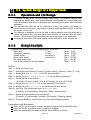
6.3.2.
Design Example
Suppose that the I/O, keys and sub-display are as follows:
Batch start:
F1 key,
Emergency stop key:
F2 key,
Dribble signal :
terminal B1,
Batch finish signal :
terminal B2,
Not used recipe code
Use default setting for the sub-display
[0thf[0thf[0utf[0utf[5q f[5ub f
2]
3]
1]
2]
8]
1]
[6]
[13]
[6]
[14]
[0]
[0]
Setup
Step 1 Enter the function list.
Step
Step
Step
Step
2
3
4
6
Select the menu F1 key.([Function] - [Function setting] - [General] - [Other] - [F1 key])
Select [6] of Batch start for the F1 key and store it.
Select [13] of Forced batch finish for the F2 key and store it.
Select the menu terminal B1.
([Function] - [Function setting] - [Control I/O Function] - [Output] - [OUT (B1)])
Step 8 Select [6] of Dribble flow for the terminal B1 and store it.
Step 9 Select [14] of Batch finish for the terminal B2 and store it.
Step 10 Set [6] of "Not used recipe code" at Recipe mode.
([Function] - [Function setting] - [Sequence] - [Basic] - [Recipe mode])
Step 11 Select [0] of the default menu and store it.
([Function] - [Function setting] - [General] - [Sub-display] - [Weighing display])
Step 12 Press the ESC key several times to return to the weinghing mode.
Operation and Response
When the F1 key is pressed, a batch weighing is started and terminal B1 works.
When the F2 key is pressed, batch weighing is stopped.
When the final weight has been achieved, terminal B2 is turned on.
Page 34
AD-4402
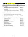
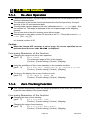
7. Weighing Mode
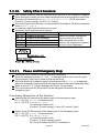
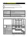
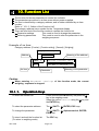
7.1.1.
Contents of the Batch Weighing Mode
Batch Weighing
Normal Batching
Normal Batching using Built-in Automatic Program Mode
Normal Batching using Customer Programmed Control Mode
Section 7.2
Section 7.3.1
Section 7.4.1
Loss-in-weigh
Loss-in-weigh using Built-in Automatic Program Mode
Loss-in-weigh using Customer Programmed Control Mode
Section 7.2
Section 7.4.1
Section 7.4.2
Selection of Batch Weighing
Section 7.2.1
Controlled Output Signals
The type of signal output to control gates (valves) in batch weighing.
Built-in Automatic Program Mode
Section 0
Section 7.4
Customer Programmed Control Mode (Comparison Output)
Partial Sequence of the Built-in Automatic Program Mode
Compensation Sequence
Initial flow Sequence
Discharge Sequence
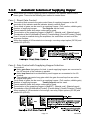
Recipe Sequence
Automatic Selection of Supplying Hopper
Nozzle Operation (vacuum cleaner)
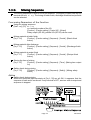
Mixing Sequence
Safety Check Function
Pause and Emergency Stop
Restart Sequence
Automatic Free Fall Compensation
Real Time Free Fall Compensation
AD-4402
Page 35
Section 7.3.3
Section 7.3.4
Section 7.3.5
Section 7.3.6
Section 7.3.7
Section 7.3.8
Section 7.3.9
Section 7.3.10
Section 7.3.11
Section 7.3.12
Section 7.3.13
Section 7.3.14
7.2. Batch Weighing Mode
This mode is used to get a (constant) final weight from a supplying hopper for the
hopper scale and filling machine. And mode can be classified as normal batch
weighing or loss-in-weigh.
There are two control methods of the customer programmed control and built-in
automatic program mode.
Normal Batching
Normal batch weighing weighs the material charged into the hopper.
Control gates (valves) can be used. (Full flow, medium flow and dribble flow)
Loss-in-weigh
Loss-in-weigh weighs the material discharged from the hopper.
Control gates (valves) can be used. (Full flow, medium flow and dribble flow)
Caution
Use PLC (programmable logic controller unit) to supply material into the
weighing hopper and monitor the bulk of material in the hopper.
Page 36
AD-4402
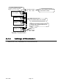
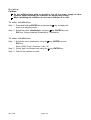
7.2.1.
Selection of Batch Weighing
Selection of Normal Batching or Loss-in-weigh
The mode can be selected at Loss-in-weigh in the Function list.
([Function] - [Function setting] - [Sequence] - [Basic] - [Current weighing])
[5q f- 3] [0]
Normal batch weighing
[5q f- 3] [1]
Loss-in-weigh
[5q f- 3] [2]
External selection (Normal batch weighing or Loss-in-weigh)
External Selection (Normal batch weighing or Loss-in-weigh)
Normal batch weighing and Loss-in-weigh can be selected by a signal at the input
terminal that is set to [9] of External switch control.
(The menu [Function] - [Function setting] - [Control I/O Function] - [Input] )
Example of use: 100 kg of material is supplied to the hopper in the first step. It is
subdivided into material of 10 kg.
Advise
If the mode is switched concerning a specified material only, set the hopper no. in the
material code, short the hopper no. output line and the supply/discharge switch input
line. Set the delay timer [5q f-32] to "above 0.1sec.".
AD-4402
Page 37
[ Blank page]
Page 38
AD-4402
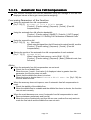
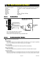
7.3. BuiltBuilt-in Automatic Program Mode
The built-in automatic program mode directly outputs control signals (example:
medium flow valve, batch finish) without a PLC.
The built-in automatic program mode can include several partial sequences like an
initial flow sequence, mixing sequence etc. into basic built-in automatic program
mode.
The power of the control I/O signal output is too small to drive a large valve directly.
Use option relay output ( OP-02 ) to drive them.
If the number of control I/O terminals is not enough, use parallel option I/O ( OP-05 ).
Forecast Control Function
This function forecasts a timing to close the dribble flow (valve) and realizes more
precise weighing. The forecast method calculates the weighing value at some points
between sampling data and compares it with the dribble setpoint. The effect is
equivalent to using a high speed A/D converter. The sampling rate of this indicator is
100 [times/second]. But the ratio is equivalent to 1000 [times/second], when this
function is used.
Caution
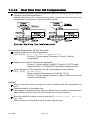
If multiple supplying hopper is used (the recipe code is used), this mode can
not be used.
Related section " 7.3.7. Automatic Selection of Supplying Hopper".
Use a high speed high, precision valve like a direct voltage solenoid valve.
Design the mechanical valve so as to minimize the delay time.
AD-4402
Page 39
7.3.1.
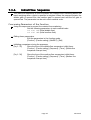
Normal Batching of BuiltBuilt-in automatic
program mode
Normal batch weighing weighs the material charged into the hopper.
Control gates (valves) can be used. (Full flow, medium flow and dribble flow)
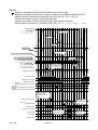
Concerning Parameters of the Function
Selecting normal batching of built-in automatic program mode.
[5q f- 1] [2] Built-in automatic program mode
[Function] - [Function setting] - [Sequence] - [Basic] - [Weighing mode]
[5q f- 3] [0] Normal batch weighing
[Function] - [Function setting] - [Sequence] - [Basic] - [Loss-in-weigh]
Setting the display to automatically when starting the sequence.
[5q f-11]
[Function] - [Function setting] - [Sequence] - [Control] - [Batch start settings]
Preventing vibration due to gate operation.
[5q f-33]
[Function] - [Function setting] - [Sequence] - [Timer] - [Full flow comparison
interrupt timer]
[5q f-34]
[Function] - [Function setting] - [Sequence] - [Timer] - [Medium flow
comparison interrupt timer]
[5q f-35]
[Function] - [Function setting] - [Sequence] - [Timer] - [Dribble flow
comparison interrupt timer]
Sending an alarm signal when the sequence time over is.
[5q f-31]
Maximum weighing time between start and batch finish can be set.
Error code [SQ.ERR 4] is displayed, when an error occurs.
[Function] - [Function setting] - [Sequence] - [Timer] - [Batch monitoring
timer]
Removing "stable" from comparison condition.
[5q f-13]
[Function] - [Function setting] - [Sequence] - [Control] - [Eval condition]
Changing the timing of comparison.
[Function] - [Function setting] - [Sequence] - [Timer] - [Eval delay timer]
[5q f-37]
Changing accuracy of comparison.
[5q f-48]
The time to average displayed value at batch finish can be set. The
timing of batch finish delays for the time.
[Function] - [Function setting] - [Sequence] - [Timer] - [Average Eval time]
Changing the pulse width of batch finish output.
[5q f-43]
If zero is set to this, the output remains until next start signal.
[Function] - [Function setting] - [Sequence] - [Timer] - [Batch finish output on]
Mixing at batch finish.
[Function] - [Function setting] - [Sequence] - [Control] - [Batch finish action]
[5q f-14]
Discharging at batch finish.
[5q f-15]
[Function] - [Function setting] - [Sequence] - [Control] - [Discharge finish
action]
Page 40
AD-4402
Using customer programmed control for OVER signal, OK signal and UNDER signal.
[5q f- 5]
[Function] - [Function setting] - [Sequence] - [Basic] - [Comparison]
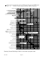
Displayed value
Preliminary
Gross weight
Final value (Target weight)
Net weight
Final value - Free fall
Free fall
Final value - Preliminary
Final value - Optional preliminary
Optional preliminary
Zero band
Tare
0
The active code is only read at
each start. And keep it.
1
Material code, Input 0
Start command, Input
5qf-32
Batch start delay timer
5qf-31
Batch monitoring timer
Time until supplying it
The whole time to
supply it
Full flow, Output
Medium flow, Output
Dribble flow, Output
5qf-33
Full flow comparison interrupt timer
5qf-34
Medium flow comparison interrupt timer
5qf-35
Dribble flow comparison interrupt timer
5qf-37
Eval delay timer
Comparison
According to 5qf-37 and stable.
5qf-13 can be set.
Stable, Output
Batch finish, Output
Over, Output
5qf-43
Batch finish output
on
Select a mode
at 5qf-05
OK, Output
Under, Output
Discharge start, Input
Discharge start delay timer
Discharge monitoring timer
If discharge sequence,
set the function.
Discharge, Output
Nearly zero, Output
Discharge gate close timer
Discharge finish, Output
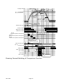
Drawing: Normal Batching of Built-in automatic program mode
AD-4402
Page 41
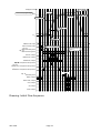
7.3.2.
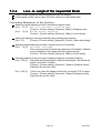
LossLoss-inin-weigh of the Sequential Mode
Loss-in-weigh weighs the material discharged from the hopper.
Control gates (valves) can be used. (Full flow, medium flow and dribble flow)
Concerning Parameters of the Function
Selecting normal batching of built-in automatic program mode.
[5q f- 1] [1] Built-in automatic program mode
[Function] - [Function setting] - [Sequence] - [Basic] - [Weighing mode]
[5q f- 3] [0] Normal batch weighing
[Function] - [Function setting] - [Sequence] - [Basic] - [Loss-in-weigh]
Setting the display to zero automatically when starting the sequence.
[5q f-11]
[Function] - [Function setting] - [Sequence] - [Control] - [Batch start settings]
Switching normal batching and loss-in-weigh from the I/O interface.
[5q f- 3] [2] External exchange
Set an input terminal to switch the mode at the I/O interface. Material
can be supplied to the hopper with three gates (valves).
[Function] - [Function setting] - [Sequence] - [Basic] - [Loss-in-weigh]
Checking whether is there enough remaining weight for one batch weighing.
[5q f-55] [1] When the remaining weight is under the final weight + zero band, the
signal "zero band" is output.
[Function] - [Function setting] - [Sequence] - [Setpoint (Compared value)] [Add final value and zero band]
[5q f-56] [1]
If this is set, when the hopper is filled fully, the signal "Full" is output.
[Function] - [Function setting] - [Sequence] - [Setpoint (Compared value)] [Add final value and full value]
Page 42
AD-4402
Displayed value
Full value
Gross weight
Full
Zero band
0
Net weight
Final value
- Final value + Optional preliminary
- Final value + Preliminary
Preliminary
- Final value + Free fall
- Final value
or -Target weight
Optional preliminary
Free fall
The active code is only read at
each start. And keep it.
Enable automatic tare to use
Tare command, Input
Material code, Input
Start command, Input
5qf-32
Start delay timer
5qf-31
Batch monitoring timer
Time until supplying it
Monitor to supply it
Full flow, Output
Medium flow, Output
Dribble flow, Output
5qf-33
Full flow comparison interrupt timer
5qf-34
Medium flow comparison interrupt timer
5qf-35
Dribble flow comparison interrupt timer
5qf-37
Eval delay timer
Comparison
Stable, Output
Batch finish, Output
Over, Output
5qf-43
batch finish output
on
Select a mode
at 5qf-05
OK, Output
Under, Output
Drawing: Loss-in-weigh of Built-in automatic program mode
AD-4402
Page 43
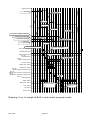
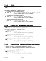
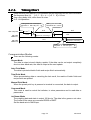
7.3.3.
Compensation Sequence
The compensation sequence is used to make up (add) the material automatically,
when the result of the current batch weighing is under weight.
Concerning Parameters of the Function
Storing a maximum repeat count of the compensation sequence.
[5q f-18]
If number is zero, this sequence is canceled. When the result is
under weight after the sequence, An error SQ.ERR 2 is displayed.
[Function] - [Function setting] - [Sequence] - [Control] - [Maximum number
of compensation]
Setting the time to open the dribble gate.
Set the time for each material code.
[Function] - [Function setting] - [MatEDIT] - [Edit] - [SF flow open timer]
Setting the time to close the dribble gate.
Set the time for each material code.
When the displayed value is stable and under weight, the
compensation is repeated. Take a longer time closing the gate, if it
does not use a stable signal.
[Function] - [Function setting] - [MatEDIT] - [Edit.] - [SF flow close timer]
Removing the nozzle at this sequence, when the nozzle operation is used.
[5q f-12] [2] Nozzle contact stop sequence
Factory setting is "not used". When it is necessary to shift up the
nozzle to reduce a weighing error, use this parameter of [5q f-12].
[Function] - [Function setting] - [Sequence] - [Control] - [Nozzle control]
Page 44
AD-4402
Displayed value
Preliminary
Free fall
Under weight
Final value (Target weight)
Net weight
Optional preliminary
0
Material code, Input
Start command, Input
Time until supplying it
The whole time to
supply it
5qf-32
Batch start delay timer
5qf-31
Batch monitoring timer
Full flow, Output
Medium flow, Output
Dribble flow, Output
5qf-37
Set maximum counts of
compensation at 5qf-18
Eval delay timer
Supplementary flow open timer
Supplementary flow close timer
Comparison
Stable, Out
Batch finish, Output
Overt, Output
OK, Output
Under, Output
Drawing: Compensation Sequence
AD-4402
Page 45
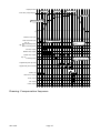
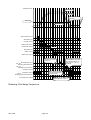
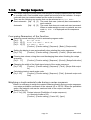
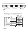
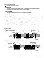
7.3.4.
Initial Flow S
Sequence
equence
The initial flow sequence is used to prevent the material from scattering before the
batch weighing when a liquid or powder is weighed. When the sequence starts, the
dribble gate is opened first, the medium gate is opened next and the full gate is
opened last. The parameter can be set in each material code.
Concerning Parameters of the Function
Using this sequence to prevent the material from scattering.
Set the following parameters in each material code.
Initial DF (Initial dribble flow)
Initial MF (Initial medium flow)
Editing these parameters.
Edit the parameters in the function mode.
[Function] - [Function setting] - [MatEDIT] - [Edit]
Inhibiting comparison during the sequence.
[5q f-35]
Store the time of the dribble flow comparison inhibit timer.
[Function] - [Function setting] - [Sequence] - [Timer] - [Dribble flow
comparison interrupt timer]
[5q f-34]
Store the time of the medium flow comparison inhibit timer.
[Function] - [Function setting] - [Sequence] - [Timer] - [Medium flow
comparison interrupt timer]
Page 46
AD-4402
Displayed value
Gross weight
Dribble
Final value (Target weight)
Net weight
Free fall
Preliminary
Initial MF
0
Initial DF
Material code, Input
Start command, Input
5qf-32
Batch start delay timer
5qf-31
Batch monitoring timer
Time until supplying it
The whole time to
supply it
Full flow, Output
Medium flow, Output
Dribble flow, Output
5qf-33
Full flow comparison interrupt timer
5qf-34
Medium flow comparison interrupt timer
5qf-35
Dribble flow comparison interrupt timer
Comparison
5qf-37
Eval delay timer
Stable, Output
Batch finish, Output
Over, Output
OK, Output
Under, Output
Drawing: Initial Flow Sequence
AD-4402
Page 47
7.3.5.
Discharge Sequence
The discharge sequence is used to discharge the material from the hopper and clear
the hopper after finishing a batch weighing.
Concerning Parameters of the Function
Storing the time between receiving a start command and opening the discharge gate.
[5q f-38]
[Function] - [Function setting] - [Sequence] - [Timer] - [Discharge start
delay timer]
Using the alarm for the discharge time limit.
[5q f-39]
If it is over, an error SQ.ERR 7 is displayed.
[Function] - [Function setting] - [Sequence] - [Timer] - [Discharge
monitoring timer]
Storing the time between cleared hopper and closing the gate.
[5q f-40]
[Function] - [Function setting] - [Sequence] - [Timer] - [Discharge gate
close delay timer]
Discharging it automatically when the weighing is finished.
[5q f-14]
When the finish signal is turned off, the discharge start timer starts.
[Function] - [Function setting] - [Sequence] - [Control] - [Batch finish
action]
Discharging it automatically when the mixing weighing is finished.
[5q f-17]
When the finish signal is turned off, the discharge start timer starts.
[Function] - [Function setting] - [Sequence] - [Control] - [Recipe finish
action]
Page 48
AD-4402
Displayed value
Gross weight
Net weight
Gross value crosses
zero band.
Zero band
Zero band.
0
Start command, Input
Start delay timer
Full flow, Output
Medium flow, Output
Comparison
Dribble flow, Output
Eval delay timer
Stable, Output
Batch finish, Output
Automatic discharge
operation can select
at 5qf-14.
Discharge start, Input
5qf-38
Discharge start delay timer
5qf-39
Discharge monitoring timer
When displayed value has
not reached the zero band
when the timer stops, An
error code SQ.ERR7 is
displayed.
Discharge, Output
When displayed value
reaches the zero band,
the timer works.
Zero Band, Output
5qf-40
Discharge gate close delay timer
5qf-44
Discharge finish output on
Discharge finish, Output
Drawing: Discharge Sequence
AD-4402
Page 49
7.3.6.
Recipe Sequence
The recipe sequence mixes preset final weights of multiple materials that are stored
in a recipe code. One hundred recipe codes can be stored in the indicator. A recipe
code can store ten material codes and the order to mix them.
There are the following two modes that can be selected at Recipe mode.
Semi-automatic [5qf- 8] [1] The mode that uses (external) start commands for
each material.
Automatic
[5qf- 8] [2] The mode that does not need each start command.
When an under weight occurs in a material, an error
code SQ.ERR 2 is displayed and the sequence
stops.
Concerning Parameters of the Function
Selecting normal batching of built-in automatic program mode.
[5q f- 8]
Recipe mode
[5q f- 8] [1] Semi-automatic mode, or
[5q f- 8] [2] Automatic mode
[Function] - [Function setting] - [Sequence] - [Basic] - [Recipe mode]
Setting the display to zero automatically when starting the recipe sequence.
[5q f-16]
[Function] - [Function setting] - [Sequence] - [Control] - [Recipe start action]
Clearing tare values, mixing them and discharging them when finishing the recipe
sequence.
[5q f- 17]
[Function] - [Function setting] - [Sequence] - [Control] - [Recipe finish action]
Changing the width of the finish signal output of the recipe sequence.
[5q f-45]
[Function] - [Function setting] - [Sequence] - [Timer] - [Recipe finish output
on]
Calculating totals in each recipe code.
[5q f-62]
[Function] - [Function setting] - [Sequence] - [Total] - [Automatic recipe code
total]
Weighing a single material code during a recipe sequence
When it is necessary to weigh the material code temporarily during a recipe sequence,
use recipe prohibition command of the external I/O or OP-05. When the prohibition
works, the material code can be used and total of the recipe is not total.
Setting of the I/O.
[1n f-nn] [49] Recipe interrupt (Prohibition of recipe sequence)
nn: terminal number of I/O.
[Function] - [Function setting] - [Control I/O] - [Input]
Page 50
AD-4402
Displayed value
Net weight
Gross weight
0
The active recipe code
is only read at each
start. And keep it.
Recipe code, Input
The material code can
not be edited during the
recipe mode.
Recipe code 1
Recipe code 2
Material code1 Material code2
Material code, Output
Material code3
Zero before the recipe
start, if necessary
Recipe start command, Input
Zero (automatic)
Tare (automatic)
Tare clear (automatic)
Material start signal (automatic)
Medium flow, Output
Dribble flow, Output
5qf-37
Comparison
Comparison
Full flow, Output
Comparison
In semi-automatic mode,
make the start signal.
Eval delay timer
Stable, Output
Batch finish, Output
Over, OK, Under, Output
Recipe finish, Output
When over or under weight occurs,
sequence stops and an error code
SQ.ERR2 is displayed. Restart to
continue this.
Discharge start, In
Discharge, Output
Discharge sequence example
Discharge finish, Output
Drawing: Recipe Sequence
AD-4402
Page 51
5qf-45
Recipe finish output on
7.3.7.
Automatic Selection of Supplying Hopper
When there are multiple supplying mats of materials, the indicator has to control
these gates. There are the following two method to control them.
Case 1: Direct Gate Control
The method that connects the gate control lines of supplying hoppers to the I/O
terminals of the indicator and the indicator directly controls them.
Three kinds of gates can be used in a supplying hopper. (Full, medium, dribble gate)
Number of supplying hopper:
Ten hoppers can be used.
Preset material codes and recipe codes can be used.
The selection of the supplying hopper is [MatEDIT] - [Material code] - [Material hopper].
The selection of the I/O terminals is [Function] - [Function setting] - [Control I/O Function] - [Output].
Even if a code is recalled during the sequence, the code does not work until the
sequence finishes.
When the number of I/O terminals is not enough, use relay output option (OP-02) and
parallel I/O (OP-05).
Case 2: Gate Control with Supplying Hopper Selection
The method:
Make gate-lines that gates of a kind, in each supplying hopper are connected to
the I/O terminal of the indicator in parallel.
Make hop-lines that lines identified by each hopper are connected to the I/O
terminal.
The indicator can control any gate which the gate-line and hop-line are active.
(logical AND gate)
Three kinds of gates can be used in a supplying hopper. (Full, medium, dribble gate)
Number of supplying hopper:
Twenty hoppers can be used.
Preset material codes and recipe codes can be used.
The selection of the supplying hopper is [MatEDIT] - [Material code] - [Material hopper].
The selection of the I/O terminals is [Function] - [Function setting] - [Control I/O function] - [Output].
When number of I/O terminals is not enough, use relay output options (OP-02) and
parallel I/O (OP-05).
Page 52
AD-4402
7.3.8.
Nozzle Control Sequence (vacuum
(vacuum cleaner)
cleaner)
The nozzle is used for filling a bottle with a liquid or powder. The procedure inserts the
nozzle into the bottle automatically using the signal "nozzle down" before the
weighing, weighs it and removes the nozzle when dribble flow is finished. Therefore,
the result (comparison) of weighing is not affected.
Advise
In case of using the nozzle control sequence
[5q f-12]
[Function] - [Function setting] - [Sequence] - [Control] - [Nozzle control]
In case of using the timer to ready nozzle.
[5q f-32]
[Function] - [Function setting] - [Sequence] - [Timer - [Batch start delay
timer]
In case of using the nozzle down
[0utf-nn]
Nozzle down
nn: terminal number of the I/O.
[Function] - [Function setting] - [Control I/O] - [Output]
In case of compare it after shifting up nozzle
[5q f-12]
[Function] - [Function setting] - [Sequence] - [Control] - [Nozzle control]
Displayed value
0
Start command, Input
Insert nozzle when receiving start signal
Inserting nozzle, Output
Start delay timer
Removing nozzle when dribble finish
Full flow, Output
Medium flow, Output
Dribble flow, Output
Comparison
Eval delay timer
Stable, Output
Batch finish, Output
AD-4402
Page 53
7.3.9.
Mixing Sequence
The mixing sequence is used to mix or stir material. The signal is output from the I/O
terminal set to mixing. The timing of batch finish, discharge finish and recipe finish
can be selected.
Concerning Parameters of the Function
Using the mixing sequence
[0utf-nn] [12] Mixing
nn: terminal number of the I/O.
[Function] - [Function setting] - [Control I/O] - [Output]
Relay output (OP-02), parallel I/O (OP-05) can be used.
Mixing material at batch finish
[5q f-14]
[Function] - [Function setting] - [Sequence] - [Control] - [Batch finish
action]
Mixing material after discharge
[5q f-15]
[Function] - [Function setting] - [Sequence] - [Control] - [Discharge finish
action]
Mixing material at recipe finish
[5q f-17]
[Function] - [Function setting] - [Sequence] - [Control] - [Recipe finish
action]
Storing the time of mixing
[5q f-47]
[Function] - [Function setting] - [Sequence] - [Timer] - [Mixing time output
on]
Safety check during mixing
[Function] - [Function setting] - [Sequence] - [Safety] - [Mixing safety
[5q f-74]
check]
Advise
Safety check during mixing
When the specified input terminals at [5q f-74] are all ON, it supposes that the
sequence is safe and is continued. If any terminal is OFF, an error code is output and
sequence is stopped.
Page 54
AD-4402
Displayed value
Gross weight
Net weight
material 1
material 2
material 3
0
Recipe start command, Input
Full flow, Output
Medium flow, Output
Dribble flow, Output
Batch finish, Output
Recipe finish, Output
5qf-47
Mixing timer
Mixing, Output
5qf-46
Output timer of mix finish
5qf-17
Set "automatic mixing start"
to continue the mixing.
Mix finish, Output
5qf-17
Set "automatic discharge start" to
continue the discharge.
Discharge, Output
AD-4402
Page 55
7.3.10.
Safety Check Function
This function is used to stop the sequence when an error or an emergency happens.
When the function works, an error code is displayed and an error signal is output from
the preset I/O terminal that weighing sequence error [22] is selected at
[Function] - [Function setting] - [Control I/O ] - [Output].
The control inputs of the function, use the preset I/O terminals or OP-05 terminals that
select safety check.
In maximum, eight input terminals can be used.
The safety check functions are as follows:
Code
Classification
Action
Condition of the start
Specify the safety confirmation
5qf-71
inputs on the I/O or OP-05.
Condition of the discharge
5qf-72
Condition of the recipe (compound) When all inputs are not ON
5qf-73
(active), the sequence is stopped,
Condition of the mix
5qf-74
an error code is displayed.
Condition of the whole sequence
5qf-75
7.3.11.
Pause and Emergency Stop
The pause input is used to stop the sequence temporarily.
When the sequence pauses, SQ.ERR 0 is displayed and an error code is output.
The emergency stop input is used to stop the sequence.
When the sequence is stopped, alarm1 is informed and No. alarm 19 is displayed.
When the emergency stop is canceled, the status moves to the pause (temporary stop).
Refer to section "7.5.11.Error Message and Alarm" for the details.
The I/O terminal and OP-05 terminal can be assigned to the pause input and
emergency input.
Concerning Parameters of the Function
Selecting the I/O terminal as the pause input or the emergency input.
[1n f-nn] [22] Pause (Temporary stop)
[1n f-nn] [13] Emergency Stop
nn: terminal number of I/O.
[Function] - [Function setting] - [Control I/O Function] - [Input]
Selecting the OP-05 terminal as the pause input or the emergency input.
[05 f-nn] [22] Pause (Temporary stop)
[05 f-nn] [13] Emergency Stop
nn: terminal number of I/O.
[Function] - [Function setting] - [slot kk]
kk: The slot number that OP-05 is installed in.
Page 56
AD-4402
7.3.12.
Restart Sequences from Pause
The restart input was used to start from the point that is stopped in the last sequence.
The control inputs of the function use the preset I/O terminals or OP-05 terminals that
select Restart.
The action of the function is as follows:
When it stopped
Before the restart
Action of the restart
During initial dribble flow
Start from initial dribble flow
During initial medium flow
Start from initial medium flow
All gates are closed
During full flow
Start from medium flow
During medium flow
Start from dribble flow
During dribble flow
Start from dribble flow
Waiting batch finish signal
Waiting batch finish signal
During compensation
Start from compensation
During nozzle operation
Stopping the operation Start from nozzle operation
During mixing
Stopping the mixing
Start from the mixing
During discharge
Stopping discharge
Start from discharge
During recipe sequence
According to above list According to above list
AD-4402
Page 57
7.3.13.
Automatic Fre
Free
e Fall Compensation
This function arranges the free fall parameter using the average of the last four
displayed values so as to get a more precise weighing.
Concerning Parameters of the Function
Using the automatic free fall compensation
[5q f-20] [1] Average of last 4 FFalls (free falls)
[Function] - [Function setting] - [Sequence] - [Control] - [Free fall
compensation]
Using the automatic free fall effective bandwidth
[Function] - [Function setting] - [MatEDIT] - [Code No.] - [AFFC range]
Refer to section 6.1.5.Editing Full Parameters of Material Code.
Using the manual free fall
[5q f-20] [0] No (Not used)
When using the signal from the I/O terminal to control free fall, use this.
[Function] - [Function setting] - [Sequence] - [Control] - [Free fall
compensation]
Storing the results of the automatic free fall compensation of each material.
[5q f- 9] [1] Change FFall
When using the flash memory, set to [0tHf-11] [2].
[Function] - [Function setting] - [Sequence] - [Basic] - [Material code, free
fall value]
Advise
When the automatic free fall compensation can not work.
Check the flux of dribble flow.
When the error (| result - final value |) of displayed value is greater than this
parameter, the function does not work.
Check that the dribble flow timer is to short.
When the timer is shorter than Dflow auto-FFall override [5q f-36], the
function does not work.
When the accuracy does not improve, even if automatic free fall compensation is
used.
Check the stability of the dribble flow.
When the dribble flow is unstable and the dribble flow timer is shorter, the function
can not work correctly.
When the result becomes over, even if automatic free fall compensation is used.
Remove between preliminary and free fall
When the value of preliminary and free fall are near, medium flow only works to
reach the final value and the dribble flow can not work.
Page 58
AD-4402
7.3.14.
Real Time Free Fall Compensation
This function arranges the free fall parameter to get more precise weighing during the
sequence (in real-time calculation).
Example: this function fits a liquid weighing (water, cement, tar) that flow rate is not
constant due to temperature, viscosity and the remains.
Concerning Parameters of the Function
Using the real time free fall compensation.
[5q f-20] [2] Real time FFall compensation
[Function] - [Function setting] - [Sequence] - [Control] - [Free fall
compensation]
Using the automatic free fall effective bandwidth
[Function] - [Function setting] - [MatEDIT] - [Code No.] - [AFFC range]
Refer to section 6.1.5.Editing Full Parameters of Material Code.
Storing the results of the automatic free fall compensation of each material.
[5q f- 9] [1] Change FFall
When using the flash memory, set to [0tHf-11] [2].
[Function] - [Function setting] - [Sequence] - [Basic] - [Memory of free fall
value by material code]
Advise
When the accuracy does not improve, even if automatic free fall compensation is
used.
Check the stability of the dribble flow.
If the material includes big lumps, when the dribble flow is unstable and irregular and
when dribble flow timer is to short, this function can not work correctly.
When the dribble flow timer is shorter than the Dflow auto-FFall override
[5q f-36].
When the timer used the default value of each material code.
AD-4402
Page 59
[ Blank page]
Page 60
AD-4402
7.4. Customer Programmed
rogrammed Control (Comparison
(Comparison Output)
Output)
The "customer programmed control mode" simply outputs the comparison results of
the setpoints and the displayed value.
The setpoint : A preset standard value to compare with the displayed value.
The comparison and output of the results are performed at each sampling time.
If this function is used, a PLC (programmable logic controller unit) is needed for batch
weighing on a hopper scale.
The power of the control I/O signal output is too small to drive a large valve directly.
Use relay output option ( OP-02 ) to drive them.
If the number of control I/O terminals is not enough, use the parallel I/O option ( OP-05 ).
Caution
Initial flow sequence and compensation sequence can not be used in the
"customer programmed control"
Advise
Automatic free fall compensation and Total function
If the start key is used, in the same as sequential mode, when three gates are closed, the
Eval timer has worked and the displayed value becomes stable, the batch finish signal
can be output.
The start key is not necessary to compare displayed values basically.
AD-4402
Page 61
7.4.1.
Normal Batching of the C
Customer
ustomer
Programmed
rogrammed Control Mode
This function outputs gate control signals that are derived from the compared setpoint
and weighing data of the materials totaled in the hopper.
When the weight increases above the setpoint, the gate control signal turns off.
When the weight decreases under the setpoint, the gate control signal turns on.
The weighing mode in this function is bi-directional. Therefore, the comparison is
repeatable (reversible).
Concerning Parameters of the Function
Using normal batching of the comparison function
[5qf- 1] [1]
Customer programmed control
[5qf- 3] [0]
Normal batch weighing
[Function] - [Function setting] - [Sequence] - [Basic]
Changing waiting time of judgment
[5qf-37]
Eval delay timer
[Function] - [Function setting] - [Sequence] - [Timer]
Changing the pulse width of batch finish output
[5qf-43]
Batch finish output on
An arbitrary width can be set.
If zero is set, the output is kept until the next start.
[Function] - [Function setting] - [Sequence] - [Timer]
Using signals of "over", "OK" and "under" in the comparison function.
[5qf- 5]
Comparison
[Function] - [Function setting] - [Sequence] - [Basic]
Changing the accuracy of the comparison
Averaging Eval time
[5qf-48]
The average time of batch finish output is set. The output of batch
finish is delayed by the average time.
[Function] - [Function setting] - [Sequence] - [Timer]
Using manual free fall compensation
[1n f-nn] [10] Manual free fall compensation
[05 f-nn] [10] Manual free fall compensation
nn: terminal number of the I/O.
The input to control free fall by an external PLC.
[Function] - [Function setting] - [Control I/O] - [Input]
Page 62
AD-4402
Displayed value
Gross weight
Free fall
Net weight
Full value
Dribble
Preliminary
Zero band
0
The active recipe code is only
read at each start. And keep it.
Material code, Input
Full flow, Output
Medium flow, Output
Dribble flow, Output
These gates work
without the start input.
5qf-33
Full flow comparison interrupt timer
5qf-34
Medium flow comparison interrupt timer
5qf-35
Dribble flow comparison interrupt timer
If the start key is used,
automatic total and
comparison can be used.
Start command, Input
Compariso
5qf-37
Waiting timer and stable.
Set the condition at 5qf-13
Eval delay timer
Stable, Output
Batch finish, Output
Over, Output
5qf-43
Batch finish output
on
OK, Output
Under, Output
Select this mode at
5qf-05
Drawing: Normal Batching of Comparison Function
AD-4402
Page 63
7.4.2.
LossLoss-inin-weigh of the Customer
Customer Programmed
rogrammed
Control Mode
This function outputs gate control signals that are derived from the compared setpoint
and weighing data of the materials from the hopper.
When the weight decreases past the setpoint, the gate control signal turns off.
When the weight increases past the setpoint, the gate control signal turns on.
The weighing mode in this function is bi-directional. Therefore, the comparison is
repeatable (reversible).
Concerning Parameters of the Function
Using loss-in-weigh of the comparison function
[5qf- 1] [1]
Customer programmed control
[5qf- 3] [1]
Loss-in-weigh
[Function] - [Function setting] - [Sequence] - [Basic]
Using the external control switch for normal batch and loss-in-weigh.
[5qf- 3] [2]
External exchange
If the external switch is used, connect it to the I/O terminals. This
mode can use three gates.
[Function] - [Function setting] - [Sequence] - [Basic]
Checking whether there are remains from the last weighing operation in the hopper.
[5qf-55]
Add final value and zero band
When the remains reach a weight that is under the final value +
zero band, the zero band signal is output.
[Function] - [Function setting] - [Sequence] - [Setpoint (Compared value)]
Using the external switch
[1n f-nn] [9] Supply switch control
nn: terminal number of the I/O.
[Function] - [Function setting] - [Control I/O] - [Input]
Checking whether there are remains from the last weighing operation in the hopper.
Add final value and full value
[5qf-56]
When the final value + full value is less than the remains (gross) in
the hopper, the full signal is output.
[Function] - [Function setting] - [Sequence] - [Setpoint (Compared value)]
Changing the accuracy of the comparison
[5qf-48]
Averaging Eval time
The average time to criticize the weight.
[Function] - [Function setting] - [Sequence] - [Timer]
Using manual compensation
[1n f-nn] [10] Manual free fall compensation
[05 f-nn] [10] Manual free fall compensation
nn: terminal number of the I/O.
The input to control free fall by an external PLC.
[Function] - [Function setting] - [Control I/O Function] - [Input]
Page 64
AD-4402
Advise
Using the automatic switch of normal batch and loss-in-weigh.
Specify the output terminal for the hopper number in the material code on the I/O.
Specify the input terminal to change the mode on the I/O. [1n f-nn] [9]
Connect the output terminal to the input terminal.
Connect the output common terminal to the input common terminal.
Set the delay time above 0.1 second at [5qf-32] Batch start delay timer.
Displayed value
Full value
Gross weight
Full
Zero band
Net weight
0
Final value
Optional preliminary
- Final value + Optional preliminary
Preliminary
- Final value + Preliminary
- Final value + Free fall
- Final value
or -Target weight
The active code is
only read at each
start. And keep it.
Free fall
Tare command, Input
Material code, Input
Full flow, Output
Medium flow, Output
Dribble flow, Output
5qf-33
Full flow comparison interrupt timer
5qf-34
Medium flow comparison interrupt timer
5qf-35
Dribble flow comparison interrupt timer
If this command is
used, total and
comparison can be
used.
Start command, Input
Comparison
5qf-37
Eval delay timer
Waiting timer
and stable.
Set the condition
at 5qf-13
Stable, Output
Batch finish, Output
5qf-43
Batch finish output
on
Over, Output
OK, Output
Under, Output
AD-4402
Page 65
Select a mode
at 5qf-05
7.5. Other Functions
7.5.1.
ReRe-Zero Operation
Performing this function, a gross display is zeroed and the current displayed value is
used as a standard point.
The operation of the function can be performed from the front panel key, the input
terminal of the I/O and command input.
The adjustable range is based on the zero calibration and Zero range [genf- 6] of
the function list. The range is displayed in the unit of percentage of the weighing
capacity.
The re-zero data is stored in memory even without power.
Resetting the re-zero data, use the I/O terminal or the F1 ~ F4 key that is set to Zero
clear [1n f-nn] [2].
nn: terminal number of I/O.
Caution
When the internal A/D converter is out of range, the re-zero operation be not
performed and the error code ZR.ERR is displayed.
Concerning Parameters of the Function
Changing the range to do the re-zero operation.
[genf- 6]
Zero range
The maximum range is 30% of the capacity.
[Function] - [Function setting] - [General] - [Weighing]
Using the prohibition of the re-zero operation in the unstable condition.
[genf- 9]
Tare and zero compensation at unstable status
[Function] - [Function setting] - [General] - [Weighing]
Turning on the display, the re-zero function is used.
[genf-13]
Clear mode at power ON
[Function] - [Function setting] - [General] - [Weighing]
7.5.2.
Zero Tracking Function
This function automatically traces the weighing deviation at the nearly zero point and
keeps the zero display of the gross display.
Concerning Parameters of the Function
Changing the time of zero tracking
[genf- 7]
Zero tracking time
[Function] - [Function setting] - [General] - [Weighing]
Changing the range of zero tracking
[genf- 8]
Zero tracking band width
[Function] - [Function setting] - [General] - [Weighing]
Page 66
AD-4402
7.5.3.
Tare
The relation of the display is as follows:
Net = Gross - Tare
Concerning Parameters of the Function
Prohibiting tare during unstable weighing
[genf- 9]
Tare and zero compensation at unstable status
[Function] - [Function setting] - [General] - [Weighing]
Prohibiting tare during negative weighing
[genf-10]
Tare at negative GROSS weight
[Function] - [Function setting] - [General] - [Weighing]
Resetting tare at turning on the indicator
[genf-13]
Clear mode at power ON
[Function] - [Function setting] - [General] - [Weighing]
7.5.4.
Preset Tare (Fixed Tare Function)
A preset tare can be stored in each material code.
Concerning Parameters of the Function
Using preset tare
[genf-11]
Preset tare
[Function] - [Function setting] - [General] - [Weighing]
Using preset tare for partial material code
Preset tare=0
[genf-12]
[Function] - [Function setting] - [General] - [Weighing]
Classifying normal tare and preset tare on the serial data
[genf-07]
Tare Header
[Function] - [Function setting] - [General] - [Weighing]
7.5.5.
Customizing the Function Key (Key Design)
Design)
Refer to" 2.2.1. Keys" of the front panel regarding key operation.
Refer to "10.4. Parameter List" of the function list regarding key function.
Concerning Parameters of the Function
Setting F1, F2, F3 and F4 keys
[0tHf- 2] to [0tHf- 5]
[Function] - [Function setting] - [General] - [Other]
AD-4402
Page 67
7.5.6.
Customizing the Sub Display
Use the default sub-display pattern, if you want to reset it.
Refer to "10.4. Parameter List" of the function list regarding these items.
Item index number to be displayed. A maximum
of 32 items of name and number can be set.
At odd: Input the name of the selected item
using alphanumeric characters.
At even: Input the number concerning the item.
Information of
key operation
5ub f 1
Sub F1-3
Name of
the item
[name]
hopper
/Row/Col/Dig
19
0
16
Items to append to sub-display
Row and Colum Address
0
1
2
3
4
5
6
7
8
5
Resize the item selected.
9 10 11 12 13 14 15 16 17 18 19 20 21 22 23 24 25 26
0
1
2
3
Row 0 and 2 are dot matrix display for alphanumerical charactor.
Row 1 and 3 are 7-segment display for numerical charactor.
Items to append to the sub-display
Number
0
1
2
3
4
5
6
7
8
9
10
11
12
13
Name and Number to Display the Item
Not displayed
Material
Hopper
Final value
Free fall
Preliminary
Optional preliminary
Over
Under
Zero Band
Full
Tare
Supplementary flow open timer
Supplementary flow close timer
Page 68
Row size
0 to 3
Columsize
0 to26
Figures
1 to12
AD-4402
Number
14
15
16
17
18
19
20
21
22
23
Name and Number to Display the Item
Automatic Free Fall Compensation
Internal reserved
Internal reserved
Initial dribble flow
Initial dribble flow
Total weight
Total count
Recipe , rCode
Total weight for recipe mode
Total counts for recipe mode
Row size
Columsize
Concerning Parameters of the Function
Setting the sub-display
[5ubf- 1] [1] Weighing display
[Function] - [Function setting] - [General] - [Sub-display]
7.5.7.
Graphic Display
Use to display a bar-graph in the sub-display.
Example:
75.00kg
material
Tot#
Code12
1500.841
■■■■■■■■■■■■■■■■
0
50
150
100
%
Bar graph
Concerning Parameters of the Function
Using the bar graph display
[5ubf- 3]
Bar graph location
[Function] - [Function setting] - [General] - [Sub-display]
Selecting the ratio of the graph display
[5ubf- 4]
Ratio of graph display
[Function] - [Function setting] - [General] - [Sub-display]
AD-4402
Page 69
Figures
7.5.8.
Total Operation
Total weight data and weighing count of each material code or recipe code.
Concerning Parameters of the Function
Using F1 ~ F4 key for total
[0tHf- 2] to [0tHf- 5]
[Function] - [Function setting] - [General] - [Other]
Using the I/O terminals for total
[1n f-nn]
nn: terminal number of the I/O.
[Function] - [Function setting] - [Control I/O] - [Input]
Using the parallel terminals for total
[05 f-nn]
nn: terminal number of the option.
n: slot number installed the option.
[Function] - [Function setting] - [slot n] - [OP-05]
7.5.9.
Undoing the Total Operation
Assign an operation input to undo the last result.
Refer to "10.4. Parameter List" of the function list regarding key function.
7.5.10.
Clearing (Deleting) the Totaled Data
Total data can be deleted (cleared) using the preset operation input.
There are four types of clearing the data.
Assign an operation input to undo the last result on the function list.
Refer to "10.4. Parameter List" of the function list regarding key function.
Page 70
AD-4402
7.5.11.
Error Message and Alarm
When the indicator detects an error in the weighing system, an error message is
displayed.
When the indicator becomes a preset condition, it is announced with the preset alarm.
Kind of error
Error no.
Error no.
Weighing error
Alarm 1
□■■■□
■□□□■
□□□□■
□□□■□
□□■□□
□■□□□
■■■■■
SQ.ERR
Over or under
amount in the
result
Error message is displayed
Error no.
SQ.ERR
ALARM 1
□□■□□
□■■□□
□□■□□
□□■□□
□□■□□
□□■□□
□■■■□
Out of range
Principle alarm links, when
multiple alarm is active.
Stop key
Kind of Alarm and Error
There is the following priority.
Weighing sequence error <
Zero error <
Alarm 1
SQ.ERR
ZR.ERR
ALARM 1
Kind
Weighing
sequence
error
SQ.ERR
AD-4402
<
Alarm 2
ALARM 2
No.
Description
When the weighing can not continue, a message is displayed and the
sequence is stoped. Cope with cause and restart the weighing.
The weighing sequence stoped.
0
Cope with cause and restart the sequence.
Safety check can not be completed.
1
Check the safety.
Under weight or over weight.
2
Compensate weight and restart.
There is a conflict in setpoint
3
Check setpoint
Time over of batch weighing.
4
Check the gate and remains of hopper.
Time over of discharge.
5
Check the discharge gate.
The remains are not enough to weigh.
6
Add material.
7
When the batch is started, the weight is full already.
8
Nozzle is touching the hopper.
Check the nozzle.
9
There is no tare (vessel) on the weighing pan.
Page 71
Kind
No.
Description
When the displayed value can not be set to zero with re-zero or tare,
Zero error the message is displayed.
0 Dispaly can not be zeroed by zero compensation.
ZR.ERR
1 Dispaly can not be zeroed by tare operation.
When the weighing value is out of range and emergency stop is
performed, this symbol is displayed.
Alarm 1
1 Weighing value is out of range.
ALARM 1
9 Emergency stop has been performed.
It can not weigh. Check the weighing system.
Example: loadcell cable, connctors.
A/D converter is positve over count.
1
Check the loadcell cable.
Alarm 2
A/D converter is negative over count.
ALARM 2
2
Check the loadcell cable.
RAM error.
4
Check the backup battery
Page 72
AD-4402
7.5.12.
Graphic Status Indicator
The indicator can display weighing status, result on the graphic indicator.
Graphic indicator
Over
OK
Under
Full flow
Medium flow
Dribble flow
□□□□□
□□□□□
□□□□□
□□□□□
□□■□□
□■■■□
■■■■■
□□□□□
□□□□□
□□□□□
□□□□□
□□□□□
□□□□□
■■■■■
□□□□□
□□□□□
□□□□□
□□□□□
□□□□□
□□□□□
□□□□□
■■■■■
■■■■■
■■■■■
■■■■■
□■■■□
□■■■□
■■■■■
■■■■■
■■■■■
■■■■■
□■■■□
□□■■□
■■■■■
■■■■■
■■■■■
■■■■■
□■■■□
□□■□□
□□□□□
□□□□□
□□□□□
□□□□□
□□□□□
□□□□□
□□□□□
■■■■■
□□□□□
□□□□□
□□□□□
□□□□□
□□□□□
□□□□□
■■■■■
□■■■□
□□■□□
□□□□□
□□□□□
□□□□□
□□□□□
□■■■□
□□□□□
□■■■□
□□□□□
□■■■□
□□□□□
■■■■■
□□■■□
□□□□□
□□■■□
□□□□□
■■■■■
■■■■■
■■■■■
□□■□□
□□□□□
■■■■■
■■■■■
■■■■■
■■■■■
■■■■■
Concerning Parameters of the Function
Using the graphic indicator
Activity indicator
[5ubf- 5]
[Function] - [Function setting] - [General] - [Sub display]
7.5.13.
Memory Backup
The indicator has two kinds of memory.
Flash memory
The memory is used to store important data without power supplied
that the occurrence of re-writing them is seldom.
Life of re-writing them is approximately 100,000 times or more.
Data example: Calibration data, Function data
Backup RAM
The memory is used to store temporary data that the occurrence of
re-writing them is often.
Life of the battery is approximately 10 years at 25 , normal use
Data example: Tare value, total data, re-zero data
When re-writing data, the sequence is stopped.
Material code and recipe code can be stored in flash memory or backup RAM.
Concerning Parameters of the Function
Selecting the memory for material code or recipe code
[0tHf-11]
Save data
[Function] - [Function setting] - [General] - [Other]
AD-4402
Page 73
8. Interface
8.1. Control I/O Function
Input terminals
Output terminals
11 lines that can select by the function
11 lines that can be selected by the function
Open collector transister
Input terminal
Input open voltage
Input drive current
Saturation tolerance voltage
Maximum
14V DC
5 mA
2 V DC
typ.
8 V DC
3 mA
Output terminal
Output voltage
Output current
Saturation tolerance voltage
8.1.1.
Maximum
40 V DC
50 mA
1.5 V at 50 mA
Interface Circuit
Max. 8 ~ 14V
Max. 5 mA
A1 ~ A 11
Input terminal
It is recommend that you use :
Mechanical switch or
open collector transistor.
Vsat < 2 V
or
A12
Input common terminal
Interface circuit in
the indicator
Max. 40V DC
Max. 50 mA
B1 ~ B 11
Output terminal
Vsat < 1.5 V at 50 mA
B12
Output common terminal
or
It is recommend that you use :
Mechanical relay with surge diode or
photo coupler.
Use a surge diode to protect the
solenoid or relay from noise.
Page 74
AD-4402
The function assigned to terminals
The function of the terminal can be assigned arbitrarily. Refer to "10.4. Parameter
List" of the function list
8.1.2.
Timing Chart
Caution
Keep the delay time to avoid abnormal-operation and noise.
Keep the input signal more than 40 ms to avoid noise and chattering.
Set the Communication mode in [01 f- 3] [without 5].
The transmission of BCD data synchronizes with displaying it in the following modes.
Stream mode, auto print mode, manual print mode and total print.
Exmaple
Approx. 20 ms width
Approx. 10 ms from new
data edge to strobe signal.
Max. 50 ms delay time to
release the hold command.
Max. 50 ms delay
time until holding data
Data output
Strobe signal
Hold input command
10ms/div
AD-4402
Page 75
8.2. BuiltBuilt-in RSRS-485 Interface
The RS-485 interface can use commands to control the indicator. The interface can
read weighing data or parameters and store parameters in the indicator.
The interface can connect a maximum of 32 units and a personal computer using a
communication cable.
Each unit is specified by an address appended to the command.
Transmission system
Data length
Start bit
Parity bit
Stop bits
Baud rate
Line
Connection
Character code
Terminator
EIA RS-485, Asynchronous, bi-directional, half-duplex
7 bits or 8 bits
1 bit
Odd, Even, not used
1 bit, 2 bits
600 bps, 1200 bps, 2400 bps, 4800 bps, 9600 bps, 19200
bps, 38400 bps
2 wires (2-balanced wires)
Max. 32 units
ASCII code
CR, CR LF
The way of Use and Notes
When useing terminator, connect it between the SDA and SDB terminals using the
accessory resistor.
If there is no signal ground at the host computer, it is not necessry to use the SG
terminal.
If the shield cable is used, connect the FG teminal to the shield line.
When connecting to RS-232C, Use AD-7491 or a converter of RS-232C/ RS-485 on a
market.
Use a multi-drop connection for command mode.
Do not use a multi-drop connection in stream mode or jet stream mode.
8.2.1.
Connection
AD-4402 Inside
RS-485
A
SDA
B
SDB
SG
A
B
SG
RE/DE
C.LOOP
FG
SG
Shield
Terminals
Interface Circuit
Page 76
AD-4402
The host computer may have
inverse polarity terminals.
Terminator resistor
100 ~ 120Ω 1/2W
The host computer may include
the terminator resistor.
SDA
Host computer SDB
SG
FG
SDA
AD-4402
Address 1 SDB
SG
FG
Use twisted-pair wire.
Use shielded cable, if it is needed.
SDA
AD-4402
Address 2 SDB
SG
FG
SDA
AD-4402
SDB
Address 32 SG
FG
Connect a terminator resistor at the
indicator that is longest distance from
the host computer.
Terminator resistor
100 ~ 120Ω 1/2W
System Connections
8.2.2.
Settings
Settings of Parameters
Refer to the "10.4. Parameter List" of the function list.
AD-4402
Page 77
8.2.3.
Timing Chart
Keep the delay time above 0.5 ms between the last response and the next command.
Set response time (tr). [r5 f- 9] < tr < [r5 f- 9] + 50 ms
Use a long delay time, when there is noise.
Hi-Z: Hi impedance
Waiting time from command to
response: tr. Set tr at [r5 f- 9].
Host computer
AD-4402
Address 1
Hi-Z
Hi-Z @01RWCRLF
Hi-Z
Waiting time until next
command: td > 0.5 ms
Hi-Z
@01ST,NT,+0123.45kgCRLF
AD-4402
Address 2
Hi-Z
@02RWCRLF
Hi-Z
@02ST,NT,+0123.45kgCRLF
Waiting time from command to
response: tr. Set tr at [r5 f- 9].
Communication Modes
There are the following modes.
Stream Mode
The data is output at each display update. If the data can be not output completely
due to a slow baud rate, the data is output at the next update.
Auto Print Mode
The data is printed at batch finish and recipe finish automatically.
Total Print Mode
When accumulating data or canceling the last result, the results of batch finish and
recipe finish are printed.
Manual Print Mode
When the preset print key is pressed or terminal is connected, the data is output.
Command Mode
This mode is used to control the indicator, to store parameters and to read data or
parameters.
Jet Steam Mode
The weighing data and state is output 100 time/s. The data is the gross or net value.
The format is the same as command RGRS or RNET.
Set the baud rate to 38400 bps.
Page 78
AD-4402
8.2.4.
General
General Data Format
This format is used for the command mode and jet stream mode.
1
2
3
4
5
6
7
8
9
10
11
12
13
14
15
16
17
18
19
20
21
22
23
24
25
26
27
R G R S 0
0
9
9
,
1
2
3
4
5
6
7
,
1
2
3
4
5
6
7
8
9
C L
R F
Header
Code
Weighing data
Terminator
Header
Command is echoed. The echoed command is 4 characters
System Monitor
Code
Material code or recipe code number. The code is 4 characters
Weighing data
Data uses BCD code, is 7 figures and does not include a decimal point.
When data is negative, a minus sign is appended to the head.
2 3 22 21 20
1 0 1 0 = Ah
ASCII code = 3Ah.
Upper 4 bits are 3h always.
Example:
System Monitor
1 2 3 4 5 6 7 8 9
0
2:
1
22:
23:
2:
0
2:
1
22:
23:
2:
0
2:
1
22:
23:
2:
0
2:
1
22:
23:
2:
Stable
Zero band
Full
Full flow
Under
Internal reservation
Internal reservation
Mixing
Mixing finish
Nozzle down
Online
During weighing sequence
Zero error
Out of range
Buzzer
During tare
Internal reservation
Terminator
CR or CR + LF
AD-4402
0
Medium flow
Dribble flow
Over
OK
0
Discharge gate
Batch finish
Recipe finish
Discharge finish
0
Internal reservation
Weighing error
Alarm 1
Alarm 2
0
Center of zero
Gross display
net display
During hold
2:
1
22:
23:
2:
2:
1
22:
23:
2:
2:
1
22:
23:
2:
2:
1
22:
23:
2:
CR: 0Dh, LF: 0Ah
Page 79
28
8.2.5.
A&D Data Format
This format is used for stream mode, auto print mode and total print.
This format is compatible to the AD-4325 indicator.
1
2
3
4
5
6
7
8
9
10
11
12
13
14
15
16
17
18
S
T
,
N
T
,
+
0
0
1
2
.
3
4
k
g
CR
LF
Header 1
Header 2
Weighing data
Unit
Terminator
Header 1
ST
Stable
US
Unstable
LO
Out of range
Header 2
GS Gross value
NT
Net value
TR
Tare value
Weighing data
Data uses BCD code, is 7 figures and includes a decimal point.
When data is negative, a minus sign is appended to the head.
When data is out of range, all numerical characters are space (20h).
Unit
kg, g or t
Terminator
CR or CR + LF
8.2.6.
CR: 0Dh, LF: 0Ah
Address
Set the address in [r5 f- 8].
32 indicators can be connected to a computer.
There is no relation between communication mode [r5 f- 2] and address [r5 f- 8].
Broadcast Address
When address @oo is used, send a command to all indicators at the same time.
Example:
@ 0
0
C
T
A
R CR LF
Address
Page 80
AD-4402
8.2.7.
Command List
Monitor Commands
Name
Read displayed value
Read gross data
Read net value
Read tare value
Read weighing result
Read setpoint or
Read comparison parameters
Code
RDSP
RW
RGRS
RNET
RTAR
RFIN
RF
RSPTxxxx
RSPT####
RSxx
RCODxxxx
RRCDxxxx
Read material code
Read recipe code
Read total data of material
RTTLxxxx
code
Read total data of recipe
RRTLxxxx
code
Read error code
RERR
xxxx:
#1:
Description
#1
To read the details of the code.
To read the details of the code.
#1
#1
#1
Material code or recipe code.
Compatible command to AD4401, AD-4403 and AD4325.
Write Commands
Name
Store setpoints
Store comparison parameters
Store material code
Store recipe code
Code
Description
WSPTxxxx
WSPT%%%%
SSxx
#1
To store optional preliminary and zero
SA
band.
#1
WCODxxxx To store all parameters of the code.
WRCDxxxx To store all parameters of the code.
xxxx: Material code or recipe code.
####: When reading an active material code or recipe code during the sequence,
place four space codes (ASCII 20h).
%%%%: When storing new parameters to material code or recipe code that is recalled
as next code in the sequence, place four space codes (ASCII 20h).
#1:
Compatible command to AD4401, AD-4403 and AD4325.
AD-4402
Page 81
Control Commands
Name
Code
CZER
Make zero display
MZ
Make zero clear
CCZR
CTAR
Tare
MT
CCTR
Tare clear
CT
CGRS
Change to gross display
MG
CENT
Change to net display
MN
CCODxxxx
Call material code
CCxx
Call recipe code
CRCDxxxx
CACC
Total command
AM
CCAC
Cancel the last result
CA
CBAT
Batch start
BB
CDSC
Discharge start
BD
Recipe start
CBLD
Mixing start
CMIX
Re-start
CRES
Stop
CHLT
CSTP
Emergency stop
HB
Clear total data of material CDTLxxxx
code
DTxx
Clear total data of all
CETL
material code
ET
Clear total data of recipe
CDRTxxxx
code
Clear total data of all
CERT
recipe code
Reset an error
CRER
No operation
CNOP
xxxx:
#1:
Description
#1
#1
#1
#1
#1
#1
#1
#1
#1
#1
#1
Total data is set to 0.
Total data is set to 0.
All total data is set to 0.
All total data is set to 0.
#1
#1
Total data is set to 0.
All total data is set to 0.
Material code or recipe code.
Compatible command to AD4401, AD-4403 and AD4325.
Page 82
AD-4402
Response Error Code
Response
?E
VE
IE
Description
The format of command is not correct.
The data of command is not correct.
Indicator is busy.
Note
When an address is used,
address is appended to the
response.
ASCII Code for AD-4402
The characters are special code for the name of material code and recipe code.
Therefor, some characters are not the same as U.S. code.
0
Upper bits
AD-4402
0
1
2
3
4
5
6
7
8
9
A
B
C
D
E
F
LF
CR
1
Lower bits
2
3
4
Space
0
@
!
"
#
$
%
&
'
(
)
*
+
,
.
/
1
2
3
4
5
6
7
8
9
:
;
<
=
>
?
Page 83
A
B
C
D
E
F
G
H
I
J
K
L
M
N
O
5
P
Q
R
S
T
U
V
W
X
Y
Z
[
]
^
_
6
Space
a
b
c
d
e
f
g
h
i
j
k
l
m
n
o
7
p
q
r
s
t
u
v
w
x
y
z
{
|
}
8.3. BuiltBuilt-in Current Loop Output
Transmission system
Current
Data length
Start bit
Parity bit
Stop bits
Baud rate
Code
8.3.1.
EIA RS-232C, Asynchronous, bi-directional, half-duplex
1 = 20mA, 0 = 0 mA, external DC current source
7 bits
1 bit
Even
1 bit
600 bps, 1200 bps, 2400 bps
ASCII code
Connection
AD-4402 inside
RS-485
A
B
SG
C.LOOP
Current loop Output
The CURRENT
LOOP terminals
do not have
polarity.
Current loop Output
FG
Shield
The current loop output has no polarity.
Use an external DC current source.
Connect the FG terminal when using a shielded cable.
8.3.2.
Communication Modes
There are the following modes.
Stream Mode
The data is output at every display update. If the data can not be output completely
due to a slow baud rate, the data is output at the next update.
Auto Print Mode
The data is printed at batch finish and recipe finish automatically.
Manual Print Mode
When the preset print key is pressed or terminal is connected, data is output.
Total Print Mode
When accumulating it or canceling the last result, the results of batch finish and recipe
finish are printed. When canceling the last results, the inverse polarity data is output.
Page 84
AD-4402
8.3.3.
Data Format
The format is the same as A&D format of the built-in RS-485.
8.4. BCD Output of Option OPOP-01
Output circuit
Output voltage
Output saturation voltage
Input control
Input open voltage
Input current
Threshold voltage
Open collector transistor
40 V DC max.
0.8 V at 25 mA
Contact to common
5 V DC 5%
5 mA max.
1.5 V max.
Connection
5V±5%
max.
5mA
Hold
B18
B20
A20
AD-4402,
OP-01 inside
25mA max.
A1
B1
max.
DC40V
Output
A1 to A18
B1 to B17
Vsat < 0.8V
at 25mA
A19、B19
Common terminals
AD-4402
Page 85
Using a PLC or photo
coupler is recommend
Terminals
When weighing display, gross display, net display or tare display [01fis used, the function of the terminals are as follows:
A1
1
B1
2
Unit
blank
A2
4
B2
8
kg
A3
10
B3
20
t
A4
40
B4
80
g
A5
100
B5
200
A6
400
B6
800
A7
1,000
B7
2,000
A8
4,000
B8
8,000
A9
10,000
B9
80,000
A10
40,000
B10
80,000
A11
100,000
B11
200,000
A12
400,000
B12
800,000
A13 Over
B13 Positive polarity
A14 Stable
B14 Net
A15 Decimal point 0.0
B15 Decimal point 0.0
A16 Decimal point 000.0
B16 Decimal point 000.0
A17 Unit 1
B17 Unit 2
A18 Strobe
B18 Hold input
A19 Common ground
B19 Common ground
A20 Frame ground
B20 Frame ground
1] [1, 2, 3, 4]
Unit 1
0
0
0
1
Unit 2
0
0
1
1
When total weight and total count [01f- 1] [5, 6, 7, 8] are used, the function of the
terminals are as follows:
A1
1
B1
2
A2
4
B2
8
A3
10
B3
20
A4
40
B4
80
A5
100
B5
200
A6
400
B6
800
A7
1,000
B7
2,000
A8
4,000
B8
8,000
A9
10,000
B9
80,000
A10
40,000
B10
80,000
A11
100,000
B11
200,000
A12
400,000
B12
800,000
A13
1,000,000
B13
2,000,000
A14
4,000,000
B14
8,000,000
A15
10,000,000
B15
20,000,000
A16
40,000,000
B16
80,000,000
A17 Over
B17
Positive polarity
A18 Strobe
B18
Hold input
A19 Common ground
B19
Common ground
A20 Frame ground
B20
Frame ground
Page 86
AD-4402
When recipe code and material code [01f- 1] [9] are used,
terminals are as follows:
A1
1 B1
Material code at
Material code at
weighing
weighing sequence
A2
4 B2
sequence
A3
10 B3
A4
40 B4
A5
Referred
1 B5
Referred material code
material code
A6
4 B6
A7
10 B7
A8
40 B8
Recipe code at
A9
1 B9
Recipe code at
weighing sequence
A10 weighing
4 B10
sequence
A11
10 B11
A12
40 B12
Referred recipe code
A13 Referred recipe
1 B13
A14 code
4 B14
A15
10 B15
A16
40 B16
A17
B17
A18 Strobe
B18
Hold input
A19 Common ground
B19
Common ground
A20 Frame ground
B20
Frame ground
When Error and alarm [01f- 1]
A1
1
Sequence error
number
A2
4
A3
Error
A4
A5
Zero error
1
number
A6
4
A7
Error
A8
A9
Alarm 1 number
1
A10
4
A11
Error
A12
A13 Alarm 2 number
1
A14
4
A15
Error
A16
A17
A18 Strobe
A19 Common ground
A20 Frame ground
AD-4402
the function of the
2
8
20
80
2
8
20
80
2
8
20
80
2
8
20
80
[10] are used, the function of the terminals are as follows:
B1
2
Sequence error
number
B2
8
B3
B4
B5
Zero error number
2
B6
8
B7
B8
B9
Alarm 1 number
2
B10
8
B11
B12
B13
Alarm 2 number
2
B14
8
B15
B16
B17
B18
Hold input
B19
Common ground
B20
Frame ground
Page 87
Communication Modes
There are the following modes.
Stream Mode
The data is output at every display update. If the data can not be output completely
due to slow baud rate, the data is output at the next update.
Auto Print Mode
The data is printed at batch finish and recipe finish automatically.
Manual Print Mode
When the preset print key is pressed or terminal is connected, data is output.
Total Print Mode
When accumulating it or canceling the last result, the results of batch finish and recipe
finish are printed. When canceling the last results, the inverse polarity data is output.
Jet Steam Mode
The weighing data and state are output 100 time/s. The data is the gross or net value.
The format is the same as command RGRS or RNET.
Set baud rate to 38400 bps.
When slow baud rate is 1/2n times 38400 bps, the same data is output 2n times
Timing Chart
When normal output [01f- 3] ≠ 5 is used
Approx. 10 ms from data
input to strobe
Approx. 20 ms of
pulse width.
50 ms of delay
time to hold it.
50 ms of delay time
to release it
Data Output
Strobe
Hold input
10ms/div
When jet steam mode output [01f- 3] = 5 is used
Approx. 1 ms from
data input to strobe
Approx. 2 ms of pulse
width.
Ignored hold
signal
Data Output
Strobe
Hold input
2ms/div
Page 88
AD-4402
8.5. Relay Output of Option OPOP-02
Rated load
250 V AC, 3 A
30 V DC, 3 A
Current at common terminal
Max. 10A DC
Minimum load
100 mV 100 µA
Life
20,000,000 times or more at no load
100,000 times or more at rated load
Connection
AD-4402
OP-02 inside
Group 1
1 Output terminal
2
3
4
5
6 common terminal 1
7 Output
8
Group 2
9
10
11 common terminal 2
Terminal List
Refer to "10.4. Parameter List" of the function list.
AD-4402
Page 89
8.6. RSRS-422/485 Interface of Option OPOP-03
The RS-422/485 interface can use commands to control the indicator. The interface
can read weighing data or parameters or store parameters to the indicator.
The interface can connect a maximum of 32 units and a personal computer using a
communication cable.
The unit is specified by an address appended to the command.
RS-485 can use 2-wire or 4- wire.
The command and format are the same as the built-in RS-485.
Transmission system
Data length
Start bit
Parity bit
Stop bits
Baud rate
Line
Connection
Character code
Terminator
EIA RS-422 / 485,
Asynchronous, bi-directional, half-duplex
7 bits or 8 bits
1 bit
Odd, Even, not used
1 bit, 2 bits
600 bps, 1200 bps, 2400 bps, 4800 bps, 9600 bps, 19200
bps, 38400 bps(Jet stream mode)
RS-422: 4 wires
RS-485: 2 wires or 4 wires
Max. 32 units
ASCII code
CR, CR LF
Caution
Either option OP-03 or OP-04 can install
Connection
AD-4402
OP-03 inside
Terminator switch
1 SDA
SD
SDA
SDB
TERMINATOR
100Ω
RDA
RDB
2 SDB
422/485
DE/RE
3 RDA
SG
4 RDB
FG
5 SG
6 FG
RD
FG
Page 90
AD-4402
RS-422 Connections
Settings
RS-422
Address Number 0
[03 f-11] [1]
[03 f- 8] [0].
Terminator resistor
100 ~ 120Ω 1/2W
Host computer SDA 1
SDB 2
RDA 3
RDB 4
SG 5
FG 6
AD-4402
The host computer may include
the terminator resistor.
TERMINATOR
ON
The host computer may have
inverse polarity terminals.
OFF
Turn on terminator
switch
SDA 1
SDB 2
RDA 3
RDB 4
SG 5
FG 6
RS-485 4 Wire Connections
Settings
RS-422
Address Number
Use twisted-pair wire.
Use shield cable, if it is needed.
[03 f-11] [1]
[03 f- 8] [without 0].
Terminator resistor
100 ~ 120Ω 1/2W
Host computer
SDA
SDB
RDA
RDB
SG
FG
The host computer may have
inverse polarity terminals.
Use twisted-pair wire.
Use shield cable, if it is needed.
AD-4402 TERMINATOR
ON
No.1
OFF
SDA
SDB
RDA
RDB
SG
FG
AD-4402 TERMINATOR
ON
No.32
OFF
Connect a terminator
resistor at the indicator that
is the longest distance from
the host computer.
SDA
SDB
RDA
RDB
SG
FG
AD-4402
The host computer may
include the terminator
resistor.
Page 91
RS-485 2 Wire Connections
Settings
RS-485
[03 f-11] [2]
Terminator resistor
100 ~ 120Ω 1/2W
Host computer
A
B
FG
The host computer may include
the terminator resistor.
The host computer may have
inverse polarity terminals.
TERMINATOR
ON
AD-4402
No.1
OFF
SDA
SDB
RDA
RDB
SG
FG
TERMINATOR
ON
AD-4402
No.32
OFF
SDA
SDB
RDA
RDB
SG
FG
2 (SDA) and 3 (SDB)
connect nothing.
Use twisted-pair wire.
Use shield cable, if it is needed.
Connect a terminator
resistor at the indicator that
is the longest distance from
the host computer.
Turn on
terminator switch
Settings of Parameters
Refer to "10.4. Parameter List" of the function list.
Timing Chart
Keep the delay time above 0.5 ms between the last response and the next command.
Set response time (tr). [03 f- 9] < tr < [03 f- 9] + 50 ms
Use a long delay time, when there is noise.
Use 4 ms or more from the output finish to receiveing the next command
Hi-Z: Hi impedance
Waiting time from command to
response: tr. Set tr at [03 f- 9].
Host computer
AD-4402
Address 1
AD-4402
Address 2
Hi-Z
@01RWCRLF
Hi-Z
Waiting time until next
command: td > 4 ms
Hi-Z
@01ST,NT,+0123.45kgCRLF
Hi-Z
Page 92
Waiting time from
command to response: tr.
Set tr at [03 f- 9].
Hi-Z
@02RWCRLF
Hi-Z
@02ST,NT,+0123.45kgCRLF
AD-4402
8.7. RSRS-232C Interface of Option OPOP-04
The RS-232C are used to connect to the DEC (modem).
The command and parameters of RS-232C is the same as the built-in RS-485.
Transmission system
EIA RS-232C,
Asynchronous, bi-directional, half-duplex
7 bits ot 8 bits
1 bit
Odd, Even, not used
1 bit, 2 bits
600 bps, 1200 bps, 2400 bps, 4800 bps, 9600 bps, 19200
bps
Data length
Start bit
Parity bit
Stop bits
Baud rate
Caution
Either option OP-03 or OP-04 can be installed.
Connection
AD-4402
OP-04 inside
FG
25
14
13
1
SG
1
FG
2
TXD
3
RXD
4
RTS
5
CTS
6
DSR
7
SG
20 DTR
Settings of Parameters
Refer to "10.4. Parameter List" of the function list.
AD-4402
Page 93
8.8. Parallel I/O of Option OPOP-05
Use this option to extend the I/O terminals
The function, settings, interface circuit and timing chart of the option is the same as
the built-in I/O terminal.
Input control
Input open voltage
Input current
Input threshold voltage
Output circuit
Output voltage
Output saturation voltage
Contact to common
7 ~ 11 V DC
5 mA max.
2 V max.
Open collector transistor
40 V DC max.
1.5 V at 50 mA
Connection
B20
B1
A1 ~ A16
A17
A18
A19
A20
B1 ~ B16
B17
B18
B19
B20
A20
A1
Input terminals
Input common
Frame ground
Output terminals
Output common
Frame ground
Terminal List
Refer to "10.4. Parameter List" of the function list.
Caution
Do not assign the same function to multiple input terminals and keys.
Page 94
AD-4402
8.9. Analog Output of Option OPOP-07
This option outputs DC current that is proportion to the display value.
Factory adjusted to 4 mA output at zero display and 20 mA output at full scale.
Analog output
Output voltage
Adaptable resistance
Update ratio
Contact to ground
11 V DC min.
0 Ω ~ 500 Ω
100 times per second with Sampling frequncy divider
[genf- 3]
Zero temperature coefficient
150 ppm/ max.
Span temperature coefficient
150 ppm/ max.
Non-linearlity
0.1% max.
Resolution
Smaller value of either 1/40000 or resolution of display
Connection
The output voltage varies
according to resistor value.
Span adjustment screw
adjusted in factory.
AD-4402
OP-07 inside
Zero adjustment screw
adjusted in factory.
Output current
Constant current source
10V max.
1
+
2
-
Connect shield
Resistor
3
FG
FG
Settings of Parameters
Refer to "10.4. Parameter List" of the function list.
Output current
22mA
20mA
When setting to
[07 f- 2] [100.00]
[07 f- 3]
[0.00]
When setting to
[07 f- 2]
[0.00]
[07 f- 3] [50.00]
When setting to
[07 f- 2]
[0.00]
[07 f- 3] [100.00]
4mA
Weighing
2mA
0.00kg
AD-4402
50.00kg
Page 95
100.00kg
9. Maintenance
9.1.1.
Basic Operation
To enter the maintenance function
Press and hold the ENTER key and press the
key in the weighing mode.
Select the menu maintenance using the key
and the ENTER key.
To select an address of the parameter The
, SHIFT +
To change the parameter
The , SHIFT +
ESC keys.
To exit the mode
(To return to the weighing mode)
The ESC key.
, ENTER, ESC keys.
, Alphanumerical, ENTER,
9.2. Monitor
Monitor Mode
The monitor mode is used to check the indicator during the weighing sequence.
9.2.1.
Monitoring the Control I/O Function
Used to monitor the status of the I/O terminals.
CONTROL
When [genf- 1] is slow, it
may not display all data.
I/O
123 kg
00010001000
a11
a1
00110100001
b11
b1
Input terminal A1
Output terminal B1
9.2.2.
Monitoring the BuiltBuilt-in RSRS-485 Interface
The current communication data is displayed.
123 kg
Parity: p
Framing:f
Received data
RNET
RNET0099,1234567,123456789
r5-485
rcu and 5nd
Page 96
Sent data
AD-4402
9.2.3.
Monitoring the BuiltBuilt-in Current Loop Output
The current communication data is displayed.
123 kg
Parity: p
Framing:f
RNET
Current loop
9.2.4.
Received data
ST,NT,+012.345kg
5nd
Sent data
Monitoring the A/D Converter
The current A/D converter data is displayed.
16.001 kg
Int.Count
160008
Internal count
9.2.5.
CAL:DS
DS: Enable
EN: Disable
Monitoring the BCD Output of OPOP-01
The current BCD output data is displayed.
12345 kg
A18
OP-01
B18
9.2.6.
001111000100011011
a18
a1
001001000001010000
b18
b1
A1
B1
Monitoring the Relay Output of OPOP-02
The status of the current relay outputs is displayed.
Output terminal
7 ~ 10
When [genf- 1] is slow, it OP-02
may not display all data.
AD-4402
123 kg
0001
10
7
Page 97
10100
5
1
Output terminal
1~5
9.2.7.
Monitoring the RSRS-422/485 Interface of OPOP-03
The current communication data is displayed.
123 kg
Parity: p
Framing:f
Received data
RNET
RNET0099,1234567,123456789
0p-03
rcu and 5nd
9.2.8.
Sent data
Monitoring the RSRS-232C Interface of OPOP-04
The current communication data is displayed.
123 kg
Parity: p
Framing: f
Received data
RNET
RNET0099,1234567,123456789
0p-04
rcu and 5nd
9.2.9.
Sent data
Monitoring the Parallel I/O of OPOP-05
The status of current parallel I/O is displayed.
OP-05
When [genf- 1] is slow, it
may not display all data.
9.2.10.
123 kg
1001000010001000
a16
a1
0101100110100001
b16
b1
Input terminal A1
Output terminal B1
Monitoring the Analog Output of OPOP-07
The current communication data is displayed.
Analog output
96.27 kg
OP-07
19.403 mA
Page 98
AD-4402
9.3. Test Mode
The test mode is used to check the indicator and weighing system with a test signal.
When the test mode is used, the weighing sequence is stopped.
Caution
The test mode outputs a test signal. Therfore, the devices connected to system
are influenced and it may cause mis-operation.
9.3.1.
Testing the Control I/O Function
Tests the output of the I/O terminals. An active output of level "1" shifts for each
terminal.
CONTROL
I/O
123 kg
00010001000
a11
a1
00100000000
b11
b1
Input terminal A1
Output terminal B1
9.3.2.
Testing the BuiltBuilt-in RSRS-485 Interface
When pressing the ENTER key each time, the test data "ST,GS,+0000000kg CR LF"
is output.
123 kg
Received data
RNET
r5-485
9.3.3.
ST,GS,+0000000kg←↓
rcu and 5nd
Sent data
Testing the BuiltBuilt-in Current Loop Output
When pressing the ENTER key each time, the test data "ST,GS,+0000000kg CR LF"
is output.
123 kg
Received data
RNET
Current loop
AD-4402
ST,GS,+0000000kg←↓
5nd
Page 99
Sent data
9.3.4.
Testing the A/D Converter
The A/D converter data is displayed.
When pressing the ENTER key, a test voltage can be input to the A/D converter.
A/D converter output
A/D Count
964583
Int.Count
160008
16.001 kg
L/C Output(mV/V)
3.103872
Test Input
0ff
Loadcell output
Internal count
9.3.5.
Test input
Testing the BCD Output of OPOP-01
Tests the output of the terminals. An active output of level "1" shifts for each terminal.
12345 kg
A18
OP-01
B18
9.3.6.
000000000000000000
a18
a1
000001000000000000
b18
b1
A1
B1
Testing the Relay Output of OPOP-02
Tests the output of the terminals. An active output of level "1" shifts for each terminal.
Output terminal
7 ~ 10
123 kg
OP-02
9.3.7.
0001
10
7
Output terminal
1~5
00000
5
1
Testing the RSRS-422/485 Interface of OPOP-03
When pressing the ENTER key each time, the test data "ST,GS,+0000000kg CR LF"
is output.
123 kg
Parity: p
Framing:f
Received data
RNET
0p-03
ST,GS,+0000000kg←↓
rcu and 5nd
Page 100
Sent data
AD-4402
9.3.8.
Testing the RSRS-232C Interface of OPOP-04
When pressing the ENTER key each time, the test data "ST,GS,+0000000kg CR LF"
is output.
123 kg
Parity: p
Framing:f
RNET
0p-04
9.3.9.
Received data
ST,GS,+0000000kg←↓
rcu and 5nd
Sent data
Testing the Parallel I/O of OPOP-05
Test the output of the terminals. An active output of level "1" shifts for each terminal.
OP-05
9.3.10.
123 kg
0000000000000000
a16
a1
0001000000000000
b16
b1
Output terminal B1
Testing the Analog Output of OPOP-07
When pressing the 1 key, the output current is increased.
When pressing the 2 key, the output current is decreased.
Analog output
96.27 kg
OP-07
20 mA
AD-4402
Input terminal A1
Page 101
9.4. Initializing Parameters
This function initializes the parameters stored in the indicator.
The parameters are stored in the flash memory and backup RAM.
Caution
There are reset functions that require re-calibration of the indicator
Note where the parameters are stored.
Kinds of intialization mode
Kinds of intialization
Initializing RAM
Description
The backup RAM is reset. Zero point of the gross display,
tare value zeroes.
Initializing material code or
Material code and recipe code is reset.
recipe code
Initializing the function list Resets parameters of the function list in flash memory.
Resets parameters of calibration data in flash memory. If
Initializing caribration data
this function is used, calibrate the indicator.
Initializing all parameters
Resets all parameters, calibrate the indicator.s
Material code
Total data
Recipe code
Total data
o
o
o
o
o
o
Calibration data
Tare
Recipe
code
Zero
Backup RAM
Material
code
Function list
The location of the parameters and objects of initialization mode
o
o
Location
Flash memory
Initialization mode
Initializing RAM
o
o
o
o
Initializing material code or
recipe code
o
o
o
o
Initializing the function list
o
Initializing caribration data
Initializing all parameters
o
o
o
Page 102
o
o
o
o
o
o
AD-4402
Prucedure
Caution
Do not initialize them while in operation. Cut off the power supply of other
systems. When initializing the indicator, the output may change.
When initializing the indicator, do not turn it off before it is reset.
To enter initialization
Step 1 Press and hold the ENTER key and press the key to display the
menu in a weighing mode.
Step 2 Select the menu "Initialization" using the
key, ENTER key and
ESC key. Category address: [Maintenance] - [Initialization]
To enter initialization
Step 1 Select the menu initialization using the
key, ENTER key and
ESC key.
Menu: RAM / Code / Function / CAL / All
Step 2 Select "yes" to initialize them using the
Step 3 Wait for the indicator to reset.
AD-4402
Page 103
key, ENTER key.
9.5. Remote Operation
This mode can read and write the parameters of the function list, data of the material
code and recipe code and calibration data.
The built-in RS-485, RS-422/485 (OP-03) or RS-232C (OP-04) is used for remote
operation.
It is necessary to install the remote setup program in the computer or controller
before use. Refer to http://www.aandd.co.jp
Refer to the instruction manual for details of the program.
Caution
Do not down load data during a weighing operation.
Remove all connections to prevent an irregular operation.
Maintain the power supply during the remote operation.
Entering the Remote Operation Mode
Step 1 Press and hold the ENTER key and press the
key.
Step 2 Press the
key to select menu remote operation. And press the ENTER
key.
Advise
The following RS-232C to RS-485 converter can be used.
AD-7491, or other converters on the market.
Page 104
AD-4402
10. Function List
The function list stores parameters to control the indicator.
The parameters are stored in an item even without power supplied.
An item is classified by a category address, and is further classified by an item
number.
Refer to " 10.1.2. Outline of the Function List".
The category address has a symbol for the 7-segments display
There are two kind of the function modes to operate the function list.
Parameter settings
This mode is used to change the parameter.
Referring parameters
This mode is used to refer the parameter in the
weighing sequence.
Example of an item:
Category address: [Function] - [Function setting] - [General] - [Weighing]
Category address symbol
Address
Item number
Meaning of the address
genf- 1
Display refresh rate
1
5 times / second
An Item
Meaning of the parameter
Parameter
Caution
When entering Parameter settings of the function mode, the current
weighing sequence is stopped.
10.1.1.
Operation Keys
To enter the function list
Press and hold the ENTER key and press the
key in the weighing mode.
Select the menu Function using the key and
the ENTER key.
To select the parameter address
The
To change the parameter
The , SHIFT +
ESC keys.
To store it and exit the function list
(To return to weighing mode)
The ESC key.
AD-4402
, SHIFT +
Page 105
, ENTER, ESC keys.
, Alphanumerical, ENTER,
10.1.2.
Outline of the Function List
Category Address
Start Item
Function
Function reference
General
genf- 1
5ub f 1
othf- 1
Weight
Sub display
Other
Sequence
Basic
Control
Timer
Setpoint (Comparison value)
Total (Accumulation)
Safety
Control I/O
5)
5)
5)
5)
5)
5)
f- 1
f-11
f-31
f-51
f-61
f-71
1n f- 1
0utf- 1
Input
Output
Serial interface
Cl f- 1
r5 f- 1
Current Loop
RS-485
Option
Slot1
Slot2
Refer to options below.
Slot3
Function setting
The same as the " Function reference".
Options
Category Address
Start Item
Option
Slot
nn (nn: Slot number for the option to be installed in)
BCD output,
OP-01
01 f- 1
Relay output,
OP-02
02 f- 1
RS-422/485,
OP-03
03 f- 1
RS-232C,
OP-04
04 f- 1
Parallel I/O,
OP-05
05 f- 1
Analog output,
OP-07
07 f- 1
Page 106
AD-4402
10.2. Referring Parameters
Use this mode to refer to the parameter in the weighing sequence.
The mode can change the parameters concerning the digital filter and weighing
sequence timers in the weighing sequence.
Digital filtering
[genf- 2]
[Function] - [Function setting] - [General] - [Weighing]
[genf- 3]
Sampling frequency divisor
[Function] - [Function setting] - [General] - [Weighing]
[5q f-31] to [5q f-48]
Weighing sequence timers
[Function] - [Function setting] - [Sequence] - [Timer]
10.3. Parameter Settings
Use this mode to change the parameters.
The weighing sequence and the I/O interfaces are stopped and closed during this
mode.
New parameters are effective after returning to the weighing mode.
AD-4402
Page 107
10.4. Parameter List
Category address: [Function] - [Function setting] - [General] - [Weighing]
Category
address
symbol
Name
genf- 1
Display refresh rate
genf- 2
Digital filter
genf- 3
Sampling
freqeuncy divider
Stability detection
time
Stability detection
band width
genf- 4
genf- 5
genf- 6
Zero Range
genf- 7
Zero tracking time
genf- 8
Zero tracking band
width
genf- 9
Tare and zero
compensation at
unstable status
genf-10
Tare at negative
GROSS weight
genf-11
Preset tare
genf-12
Preset tare =0
choice
Descriptions
1: Five times per second
2: Ten times per second
0: Not used Select 3dB band for two
1: 11 Hz
low pass filters.
2: 8.0 Hz
3: 5.6 Hz
A/D converter
4: 4.0 Hz
5: 2.8 Hz
First filter
6: 2.0 Hz
7: 1.4 Hz
8: 1.0 Hz
Second filter
9: 0.7 Hz
Use to decrease the cut-off frequency of
the digital filter.
The detection condition concerning
satblility.
0.0 : stable at anytime.
The range to zero the gross display.
Center of range is zero calibration.
Unit: percentage of weighing capacity.
The function automatically traces the
weighing deviation at nearly zero
point and keeps zero display of gross
display.
When unstable weghing, whether zero
or tare command is used.
0 :Disabled
1 :Enabled
When negative weghing, whether tare
command is used.
0 :Prohibit tare.
1 : Permission to tare.
Preset tare of material code
0 :Not used
1 :Use
1: If tare value of material code is zero,
the last tare value is used.
2: If tare value of material code is zero,
Tare is set to zero.
Page 108
Range
and
choices
1 to 2
Default
2
0 to 99
4 8
0 to 10
0.0 to
9.9 s
0.0 to
9.9 d
1
1.0 s
2.0 d
0 to 30 % 5 %
0.0 to
9.9 s
0.0 to
9.9 d
0.0 s
0.0 d
0 to 1
1
0 to 1
1
0 to 1
1
1 to 2
1
AD-4402
Category
address
symbol
genf-13
genf-14
s:
d:
AD-4402
Name
Clear mode at
power ON
Hold function
Descriptions
The action at turning the indicator on.
First bit:
Zero
Second bit: Zero clear
Third bit: Tare
Fourth bit: Tare clear
0:
1:
1:
2:
3:
Not used
Use
Hold
Hold at batch finish
Hold at recipe finish
second
digit
Page 109
Range
and
choices
Default
0000 to
1111
0000
1 to 3
1
Category address: [Function] - [Function setting] - [General] - [Sub-display]
Category
address
symbol
5Ubf- 1
Name
Weighing display
Range
and
choices
Descriptions
0: Basic format
1: Custom format
0 to 1
Default
0
When custom format is used (When [5Ubf- 1] [1] ), set items to be displayed in the
sub-display.
Item index number to be displayed. 32 items of name and number can be set in maximum.
Odd:
Input the name of the selected item using alphanumeric characters.
Even:
Input the number concerning the item.
5ub f 1
Sub F1-3
[name]
hopper
Name of
the item
Number
0
1
2
3
4
5
6
7
8
9
10
11
12
13
14
15
16
17
18
19
20
21
22
23
Information of
key operation
/Row/Col/Dig
19
0
16
5
Resize the item selected.
Name and Number to Display the Item
Not displayed
Material
Hopper
Final
Free fall
Preliminary
Optional preliminary
Over
Under
Zero Band
Full (full filling)
Tare
Supplementary flow open timer
Supplementary flow close timer
Automatic Free Fall Compensation
Internal reserved
Internal reserved
IDF at initial flow sequence
MDF at initial flow sequence
Total weight
Total count
Recipe , rCode
Total weight for recipe mode
Total count for recipe mode
Page 110
Row size
Columsize
Figures
0 to 3
0 to26
1 to12
AD-4402
Category address: [Function] - [Function setting] - [General] - [Sub-display]
Category
address
symbol
5Ubf- 2
Name
Recipe display
Range
and
choices
Descriptions
0: Basic format
1: Custom format
0 to 1
Default
0
When custom format is used (When [5Ubf- 2] [1] ), set items to be displayed in the
sub-display.
Item index number to be displayed. 32 items of name and number can be set in maximum.
Odd:
Input the name of the selected item using alphanumeric characters.
Even:
Input the number concerning the item.
Information of
key operation
5ub f 2
Sub F2-3
[name]
rTotal
/Row/Col/Dig
22
0
16
Name of
the item
Resize the item selected.
Number Name and Number to Display the Item
0
Not displayed
22
Total weight for recipe mode
23
Total count for recipe mode
AD-4402
5
Page 111
Row size
Columsize
Figures
0 to 3
0 to26
1 to12
Category address: [Function] - [Function setting] - [General] - [Sub-display]
Category
address
symbol
5ub f 1
5ub f 2
Name
Descriptions
Range
and
choices
Default
Refer to previous pages.
5ub f 3
Bar graph location
5ub f 4
Ratio of graph
display
5ub f 5
Activity indicator
0:
1:
2:
1:
2:
0:
1:
Hide
Upper side.
Lower side.
Gross weight to capacity.
Net weight to final value.
Off (Not used)
On (Use)
0 to 2
0
0 to 2
1
0 to 1
1
Category address: [Function] - [Function setting] - [General] - [Others]
Category
address
symbol
othf- 1
Name
Key lock
Descriptions
Set the action of each key.
Bit 1: F1 key
Bit 2: F2 key
Bit 3: F3 key
Bit 4: F4 key
Bit 5: Code recall key
Bit 6: Code set key
Bit 7: Not defined
Bit 8: Zero key
Bit 9: Tare key
Bit 10: Net / Gross key
Bit 11: Not defined
Bit 12: Off key
Range
and
choices
Default
0000000
00000 to
1111111
11111
00000
00000
00
0: Unlock
1: Lock
Page 112
AD-4402
Category
address
symbol
Name
othf- 2
F1 key function
othf- 3
F2 key function
othf- 4
F3 key function
othf- 5
F4 key function
othf- 6
Parallel I/O Buzzer
Descriptions
0:
1:
2:
3:
4:
5:
6:
7:
8:
9:
10:
11:
12:
13:
14:
15:
16:
17:
18:
19:
20:
Not used
Display exchange (current weighing / recipe)
Manual print
Hold
Zero clear ( to be zero)
Tare clear ( to be zero)
Batch start
Recipe start
Discharge
Mixing
Pause
Internal reseved
Restart
Forced batch finish
Forced recipe finish
Forced discharge finish
Total command
Manual free fall compensation
Cancel the last result
Error reset
Clear the total weight and count for
each material code.
21: Clear the total weight and count for
each recipe code.
22: Clear all total data for material codes.
23: Clear all total data for recipe codes.
24: Clear all total data of material code
and recipe code.
Buzzer output is 2 s. Beep is 0.2 s used
in Contolol I/O, OP-02, OP-05.
Bit 1: Beep (Click sound)
Bit 2: Over
Bit 3: OK
Bit 4: Under
Bit 5: Zero band
Bit 6: Bach finish
Bit 7: Discharge finish
Bit 8: Recipe finish
Bit 9: Mixing finish
Bit 10: Weighing sequence in process
Bit 11: Full (Full filling)
Bit 12: Stable condition
Bit 13: Weighing sequence error
Bit 14: Alarm 1
Bit 15: Alarm 2
Bit 16: Zero error
0: Off (Not used: Open)
1: On (Use: Short or Open)
AD-4402
Page 113
Range
and
choices
Default
0 to 24
0
0000000
0000000
00
to
1111111
1111111
11
10000
00000
00000
0
Category
address
symbol
Name
othf- 7
Tare Header
othf- 8
Preset tare printing
with net weight
othf- 9
Printing when
unstable condition
othf-10
Repeat lock
othf-11
Save data
Descriptions
Range
and
choices
Use for the current loop output or
RS-485 of serial interface.
This parameter can not be used in
command mode or stream mode.
0 to 1
0: All tare header of tare is "TR"
1: Use "PT" for preset tare header and
"T" of tare header
Use for the current loop output or
RS-485 interface at net display.
This parameter can not be used in
0 to 1
command mode or stream mode.
0: No (Preset tare not output)
1: Yes (To output preset tare)
Use for the current loop output or
RS-485 interface at "out of range" or
"unstable condition".
0 to 1
0: No
1: Yes
The function to avoid key operation
error.
Bit 0: Total
Bit 1: Manual print operaton
00 to 11
0: Unlock
1: Lock (Cancel duplicated command
input)
Select a backup method for material
code and recipe code.
0: Store in RAM
1: Store in flash memory
Page 114
1 to 2
Default
0
0
0
00
1
AD-4402
Category address: [Function] - [Function setting] - [Sequence] - [Basic]
Category
address
symbol
5q f- 1
5q f- 3
5q f- 4
5q f- 5
5q f- 7
5q f- 8
5q f- 9
AD-4402
Name
Descriptions
1: Customer programmed control mode
2: Built-in automatic program mode
0: Normal batch weighing
Loss-in-weigh
1: Loss-in-weigh
2: External exchange
Setpoint
0: Comparison with internal count
comparison
1: Comparison with display count
0: Always output
Comparison
1: Stable condition
2: At batch finish
0: Gross <= Zero band
Output of zero band
1: | Gross | <= Zero band
0: recipe sequence not used
Recipe mode
1: Semi-automatic mode
2: Automatic mode
The selection to store free fall value on
the automatic free fall compensation
or realtime free fall compensation.
0: No change
Even if automatic free fall
Material code, free
compensation is used, parameter
fall value
of the free fall stored in the material
code is not changed.
1: Change free fall value
The result is stored in the parameter
of the free fall in the material code.
Weighing mode
Page 115
Range
and
choices
Default
1 to 2
2
0 to 2
0
1 to 2
1
0 to 2
2
1 to 2
1
0 to 2
0
0 to 1
0
Category address: [Function] - [Function setting] - [Sequence] - [Control]
Category
address
symbol
5q f-11
5q f-12
5q f-13
Name
Batch start settings
Nozzle control
Eval conditions
Descriptions
Range
and
choices
Select an action at starting the weighing
sequence.
Bit 1: When loading it above zero
band, start the sequence.
Bit 2: Not used
000 to
Bit 3: Automatic tare at the starting
111
sequence
0: No
(Does not work)
1: Yes (Works)
Bit 1: Use nozzle control.
"Nozzle down" operation signal
is output at starting the
sequence.
Bit 2: Nozzle contact stop sequence
Use start delay timer to prevent 000 to
weighing error at touching the 111
hopper.
Bit 3: "Nozzle up" after compensate.
0: No
(Not used)
1: Yes (Use)
After dribble flow, select the stablility
condition of comparison. Refer to Eval
delay timer [5qf-37].
0: Timer is up
Compare when time is up.
1: Stable and timer is up
0 to 2
Compare when weighing is stable
and the time is up.
2: Stable or timer is up
Compare when weighing is stable or
the time is up.
Page 116
Default
000
000
1
AD-4402
Category address: [Function] - [Function setting] - [Sequence] - [Control]
Category
address
symbol
5q f-14
5q f-15
5q f-16
5q f-17
Name
Batch finish actions
Discharge finish
actions
Select an action at batch finish.
Bit 1: Auto-start mixing
(Start mixing automatically)
00
Bit 2: Auto-start discharge
(Start discharge automatically) to
11
0: No
(Not used)
1: Yes (Use)
Select an action at discharge finish.
Bit 1: Auto-clear tare
(Clear tare automatically)
Bit 2: Start mixing
(Start mixing automatically)
0: No
(Not used)
1: Yes (Use)
Selection of re-zeroing at recipe start.
(Not used)
Recipe start actions 0: No
1: Yes (Use)
Select an action at recipe finish.
Bit 1: Auto-clear tare
(Clear tare automatically)
Bit 2: Auto-start mixing
(Start mixing automatically)
Recipe finish
Bit
3:
Auto-start discharge.
actions
(Start discharge automatically)
5q f-18
Maximum number
of compensation
5q f-19
Comparison flow
Eval
5q f-20
Free fall
compensation
AD-4402
Descriptions
Range
and
choices
0: No
(Not used)
1: Yes (Use)
Set the number of compensation flow.
When 0 is set, there is no flow.
Set the condition with compensation
close timer and stability.
0: Timer is up
Comparison when compensation
close timer is up.
1: Stable and timer is up.
Comparison after stable mark and
compensation close timer is up.
2: Stable or timer is up.
Comparison after stable mark or
compensation close timer is up.
0: No
(Not used)
1: Average of last four free fall times.
2: Real time free fall compensation
Page 117
Default
00
00
to
11
00
0 to 1
1
000
to
111
000
0 to
255
0
0 to 2
0
0 to 2
0
Category
address
symbol
5q f-21
Name
Batch finish output
off
Descriptions
0: Off at next start
(Turning off until next start)
1: Off at over or unstable.
(Turning off when "out of range" or
"unstable condition")
2: Off at zero band.
(Turning off at zero band)
Range
and
choices
0 to 2
Default
0
Category address: [Function] - [Function setting] - [Sequence] - [Timer]
Category
address
symbol
Name
5q f-31
Batch monitoring
timer
5q f-32
Batch start delay
timer
Full flow
comparison
interrupt timer
Medium flow
comparison
interrupt timer
Dribble flow
comparison
interrupt timer
5q f-33
5q f-34
5q f-35
5q f-36
Dribble flow
auto-Free Fall
override
5q f-37
Eval delay timer
5q f-38
Discharge start
delay timer
Descriptions
Set the upper limit of the time of
sequence.
If the sequence is not finnished,
sequence error SQ.ERR4 is displayed.
If 0 is set, the timer does not work.
Set the delay time between start
operation and the flow start
The timer to prevent weighing error due
to vibration of open/close operation.
While the timer is not up, the
comparison does not work.
Set the time until the dribble flow can
start.
Use to prevent compensation error of
automatic free fall compensation or
real time free fall compensation.
Set the time between closing dribble
flow and comparing the result. Refer to
Eval conditions [5q f-13]
Set the time between operating
discharge start and opening the
discahrge gate
Page 118
Range
and
choices
Default
0 to
65535 s
0s
0.0 to
65535 s
0.0 s
0.0 to
25.5 s
0.0 s
0.0 to
25.5 s
0.0 s
0.0 to
25.5 s
0.0 s
0.0 to
25.5 s
3.0 s
0.1to
25.5 s
0.1 s
0.0 to
25.5 s
0.0 s
AD-4402
Category
address
symbol
5q f-39
5q f-40
5q f-43
5q f-44
5q f-45
5q f-46
5q f-47
5q f-48
s:
d:
AD-4402
Name
Descriptions
Set the time limit to discarge it
When time is up and displayed value is
Discharge
not zero band, sequence error
monitoring timer
SQ.ERR5 is displayed.
If 0 is set, the timer does not work.
Set the waiting time from reaching to
Discharge gate
zero band to closing discharge gate for
close delay timer
gross.
Set the active (ON) time of the batch
Batch finish output
finish signal. If 0 is set, output is kept
on
until next sequence.
Discharge finish
Set the active (ON) time of the ON for
output on
the discharge signal.
Recipe finish output Set the active (ON) time of the ON for
on
the recipe finish signal.
Mixing finish output Set the active (ON) time of the ON for
on
the mixing finish signal.
Mixing time output Set the active (ON) time of the ON for
on
the mixing time signal.
Set the time to average the result. This
time controls precision of the result.
Averaging Eval time Refer to Eval delay timer [5q
f-37] and Eval conditions [5q
f-13].
second
digit
Page 119
Range
and
choices
Default
0 to
65535 s
0s
0.1 to
25.5 s
0.1 s
0.00 to
2.55 s
0.00 s
0.00 to
2.55 s
0.00 to
2.55 s
0.00 to
2.55 s
0 to
255 s
00.0 to
2.55 s
0.00 s
0.00 s
0.00 s
0s
0.00 s
Category address: [Function] - [Function setting] - [Sequence] - [Setpoint]
Category
address
symbol
5q f-51
5q f-53
5q f-55
5q f-56
Name
Descriptions
1: Key operation (including serial
interface, field bus)
Code recall method
2: Parallel interface (Digital switch)
3: External switch
Select the parameter to hide of material
code.
Bit 1: Free fall
Bit 2: Preliminary
Bit 3: Optional preliminary
Bit 4: Over
Bit 5: Under
Bit 6: Zero band
Hide elements of
Bit 7: Full
Bit 8: Tare
material code
Bit 9: Compensation flow open timer
Bit 10: Compensation flow close timer
Bit 11: AFFC range
Bit 12: Initial dribble flow
Bit 13: Initial dribble flow
0:
1:
Add Final value and 0:
zero band
1:
Add Final value and 0:
Full value
1:
Show
Hide
No
Yes
No
Yes
(Not added)
(Add)
(Not added)
(Add)
Range
and
choices
Default
1 to 3
1
0000000
000000
to
1111111
111111
00000
00000
000
0 to 1
1
0 to 1
1
Category address: [Function] - [Function setting] - [Sequence] - [Total]
Category
address
symbol
Name
5q f-61
Automaic material
code total
5q f-62
Automaic recipe
code total
Descriptions
0: Not totaled automatically
1: Auto-total OK results
To total OK result automatically
2: Auto-total all results
To total all result automatically
0: No
(Not totaled)
1: Yes
(Total the result)
Page 120
Range
and
choices
Default
0 to 2
0
0 to 1
0
AD-4402
Category address: [Function] - [Function setting] - [Sequence] - [Safety]
Category
address
symbol
Name
5q f-71 to 5q f-75
5q f-71
5q f-72
5q f-73
5q f-74
5q f-75
AD-4402
Range
and
Default
choices
The maximum eight inputs for safty check are assigned to the
I/O or OP-05. If an input is inactive, the sequence is stopped
and displays sequence error. Refet to 7.5.11. Error Message
and Alarm. These safety checks can be used during the
sequence.
Descriptions
Bits map
Bit 1:
Safety input 1
Bit 2:
Safety input 2
Bit 3:
Safety input 3
Bit 4:
Safety input 4
Bit 5:
Safety input 5
Bit 6:
Safety input 6
Bit 7:
Safety input 7
Bit 8:
Safety input 8
0: No
(Not used)
1: Yes (Use)
If the assigned input is inactive during
Batching safety
the weighing sequence, a sequence
check
error occurs.
If the assigned input is inactive during
Discharge safety
the discharge sequence, a sequence
check
error occurs.
If the assigned input is inactive during
Recipe safety
the recipe sequence, a sequence error
check
occurs.
If the assigned input is inactive during
Mixing safety check the mixing sequence, a sequence error
occurs.
General safety
If the assigned input is inactive during all
check
sequences, a sequence error occurs.
Page 121
0000000
0
to
1111111
1
00000
000
Category address: [Function] - [Function setting] - [Control I/O Function] - [Input]
The list to assign the function for the input terminal of the I/O
No.
Function description
Read No.
Function description
26
Clear totals of active recipe
0
No function
code
1
Zero
Edge 27
Clear totals of all recipe code
2
Zero clear
Edge 28
Safety check input 1
3
Tare
Edge 29
Safety check input 2
4
Tare clear
Edge 30
Safety check input 3
5
Batch start
Edge 31
Safety check input 4
6
Recipe start
Edge 32
Safety check input 5
7
Discharge start
Edge 33
Safety check input 6
8
Mixting
Edge 34
Safety check input 7
External switch control
Level 35
Safety check input 8
9
0: Normal bach
1: Loss-in-weigh
10
Manual free fall compensation Edge 36
Forced batch finish
11
Total command
Edge 37
Forced recipe finish
12
Cancel the last result
Edge 38
Forced discharge finish
13
Emergency stop
Level 39
Manual full flow
Material / Recipe code,
Level 40
Manual medium flow
14
BCD
1
Material / Recipe code,
Level 41
Manual dribble flow
15
BCD
2
Material / Recipe code,
Level 42
Manual discharge
16
BCD
4
Material / Recipe code,
Level 43
Manual mixing
17
BCD
8
Material / Recipe code,
Level 44
Error reset
18
BCD 10
Material / Recipe code,
Level 45
Hold
19
BCD 20
Material / Recipe code,
Level 46
Key unlock
20
BCD 40
Material / Recipe code,
Level 47
Manual print command
21
BCD 80
Edge 48
Code recall external switch control
22
Pause
OFF: key, ON: digital switch
23
Restart
Edge 49
Recipe interrupt
Clear totals of active material
Edge 50
Net / gross
24
code
25
Clear totals of all material code Edge
Page 122
Read
Edge
Edge
Level
Level
Level
Level
Level
Level
Level
Level
Edge
Edge
Edge
Level
Level
Level
Level
Level
Edge
Level
Level
Edge
Level
Level
Edge
AD-4402
Input terminals of the I/O and default functions
Category
address
Terminal name
Default choices
symbol
Zero
1n f- 1 Input terminal A1
Tare
1n f- 2 Input terminal A2
Input
terminal
A3
Tare clear
1n f- 3
Batch start
1n f- 4 Input terminal A4
Emergency stop
1n f- 5 Input terminal A5
Material / Recipe code,
1n f- 6 Input terminal A6
BCD
1
Material / Recipe code,
1n f- 7 Input terminal A7
BCD
2
Material / Recipe code,
1n f- 8 Input terminal A8
BCD
4
Pause
1n f- 9 Input terminal A9
Restart
1n f-10 Input terminal A10
Error reset
1n f-11 Input terminal A11
AD-4402
Page 123
Defau
lt No.
1
3
4
5
13
14
15
16
22
23
44
Category address: [Function] - [Function setting] - [Control I/O Function] - [Output]
The list to assign the function for the output terminal of the I/O
No.
Function description
No. Function description No.
0 No function
30 Gross display
60
1 Stable
31 Net display
61
2 Zero band
32 During hold
62
3 Full (Full filling)
33 Internal reservation
63
4 Full flow
34 Internal reservation
64
5 Medium flow
35 Material hopper 1
65
6 Dribble flow
36 Material hopper 2
66
7 Over
37 Material hopper 3
67
8 OK
38 Material hopper 4
68
9 Under
39 Material hopper 5
69
10 Internal reservation
40 Material hopper 6
70
11 Internal reservation
41 Material hopper 7
71
12 Mixing
42 Material hopper 8
72
13 Discharge (Open the dscharge gate) 43 Material hopper 9
73
14 Batch finish
44 Material hopper 10
74
15 Recipe finish
45 Material hopper 11
75
16 Discharge finish
46 Material hopper 12
76
17 Mixing finish
47 Material hopper 13
77
18 Nozzle down
48 Material hopper 14
78
Online. If sequence is
49 Material hopper 15
79
19 enabled, 0.5 sec. pulse is
output.
Weighing sequence in
50 Material hopper 16
80
20
process
Input acknowledge.
51 Material hopper 17
81
21 If there is a input signal, 0.5
sec. pulse is output.
22 Weighing sequence error
52 Material hopper 18
82
23 Alram 1
53 Material hopper 19
83
24 Alram 2
54 Material hopper 20
84
25 Zero error
55 Material hopper 1 FF
Capacity exceeded
56 Material hopper 1 MF
26
(Out of range)
27 Buzzer
57 Material hopper 1 DF
28 During tare
58 Material hopper 2 FF
29 Center of zero
59 Material hopper 2 MF
Full flow:
Medium flow:
Dribble flow:
Function description
Material hopper 2 DF
Material hopper 3 FF
Material hopper 3 MF
Material hopper 3 DF
Material hopper 4 FF
Material hopper 4 MF
Material hopper 4 DF
Material hopper 5 FF
Material hopper 5 MF
Material hopper 5 DF
Material hopper 6 FF
Material hopper 6 MF
Material hopper 6 DF
Material hopper 7 FF
Material hopper 7 MF
Material hopper 7 DF
Material hopper 8 FF
Material hopper 8 MF
Material hopper 8 DF
Material hopper 9 FF
Material hopper 9 MF
Material hopper 9 DF
Material hopper10 FF
Material hopper10 MF
Material hopper10 DF
FF
MF
DF
Page 124
AD-4402
Output terminals of the I/O and default functions
Category
address
Terminal name
Default choices
symbol
Zero band
0utf- 1 Output terminal B1
Full flow
0utf- 2 Output terminal B2
Output
terminal
B3
Medium flow
0utf- 3
Dribble flow
0utf- 4 Output terminal B4
Over
0utf- 5 Output terminal B5
OK
0utf- 6 Output terminal B6
Under
0utf- 7 Output terminal B7
Batch finish
0utf- 8 Output terminal B8
Weighing sequence error
0utf- 9 Output terminal B9
Alarm 1
0utf-10 Output terminal B10
Output
terminal
B11
Alarm 2
0utf-11
AD-4402
Page 125
Defau
lt No.
2
4
5
6
7
8
9
14
22
23
24
Category address: [Function] - [Function setting] - [Serial] - [RS-485]
Category
address
symbol
Name
r5 f- 1
Output data
r5 f- 2
Communication
mode
r5 f- 3
Baud rate
r5 f- 4
Parity check
r5 f- 5
Character length
r5 f- 6
Stop bits
r5 f- 7
Terminator
r5 f- 8
Address
r5 f- 9
Response timer
Descriptions
When jet stream mode of
communication mode [r5 f- 2] is used,
1, 2 or 3 can be selected. And if freeze
mode is used in jet stream mode, output
is stoped.
1: Displayed value
2: Gross value
3: Net value
4: Tare value
5: Gross value/ Net value/ Tare value
6: Displayed value with material code
7: Gross value with material code
8: Net value with material code
9: Tare value with material code
10: Gross value/ Net value/ Tare value
with material code
1: Stream mode
2: Auto print mode
3: Manual print mode
4: Print at total
5: Jet stream mode
6: Command mode
1: 600 bps
2: 1200 bps
3: 2400 bps
4: 4800 bps
5: 9600 bps
6: 19200 bps
7: 38400 bps (command mode can not
be selected)
0: Not used
1: Odd
2: Even
7: 7 bits
8: 8 bits
1: 1 bit
2: 2:bits
1: CR
CR: 0Dh
2: CR LF
LF: 0Ah
0:
Address not used
1 to 99: Address used
Set the waiting timer from receiving
command to transmitting a response.
Page 126
Range
and
choices
Default
1 to 10
1
1 to 6
6
1 to 7
5
0 to 2
0
7, 8
8
1 to 2
1
1 to 2
2
0 to 99
0
0.0 to
25.5 s
0.0 s
AD-4402
Category address: [Function] - [Function setting] - [Serial] - [Current loop]
Category
address
symbol
Name
Cl f- 1
Output data
Cl f- 2
Communication
mode
Cl f- 3
Baud rate
Cl f- 4
Burst rate of
continuous output
Descriptions
1:
2:
3:
4:
5:
6:
7:
8:
9:
10:
Displayed value
Gross value
Net value
Tare value
Gross value/ Net value/ Tare value
Displayed value with material code
Gross value with material code
Net value with material code
Tare value with material code
Gross value/ Net value/ Tare value
with material code
1: Stream mode
2: Auto print mode
3: Manual print mode
4: Print at total
5: Jet Stream mode
1: 600 bps
2: 1200 bps
3: 2400 bps
Set the burst time when gross, net or
tare is output continuously.
Stream mode uses 0.0 s.
s: Second
AD-4402
Page 127
Range
and
choices
Default
1 to 10
1
1 to 4
1
1 to 3
3
0.00 to
2.55 s
0.00 s
Category address: [Function] - [Function setting] - [Option] - [slotn] - [OP-01]
OP-01: Option BCD Output
Category
address
symbol
slot n : slot number
Name
01 f- 1
Out put data
01 f- 3
Communication
mode
01 f- 4
Output logic
Descriptions
1:
2:
3:
4:
5:
6:
7:
8:
9:
Displayed value
Gross value
Net value
Tare value
Current material code total
Current material code total #
Current recipe code total
Current recipe code total #
Current material code and recipe
code
10: Error alarm No.
1: Stream mode
2: Auto print mode
3: Manual print mode
4: Print at total
5: Jet stream mode (each sampling)
1: Positive logic
2: Negative logic
Page 128
Range
and
choices
Default
1 to 10
1
1 to 5
1
1 to 2
2
AD-4402
Category address: [Function] - [Function setting] - [Option] - [slotn] - [OP-02]
OP-02: Option Output Relay Output
Category
address
symbol
02 f- 1
02 f- 2
02 f- 3
02 f- 4
02 f- 5
02 f- 7
02 f- 8
02 f- 9
02 f-10
Name
Output terminal 1
Output terminal 2
Output terminal 3
Output terminal 4
Output terminal 5
Output terminal 7
Output terminal 8
Output terminal 9
Output terminal 10
slot n : slot number
Descriptions
Material hopper 1
Material hopper1
Material hopper 2
Material hopper 2
Material hopper 3
Material hopper 3
Material hopper 4
Material hopper 4
Material hopper 5
Medium flow
Dribble flow
Medium flow
Dribble flow
Medium flow
Dribble flow
Medium flow
Dribble flow
Medium flow
Default parameters are set to double gates hopper
AD-4402
Page 129
Range
and
choices
0 to 84
0 to 84
0 to 84
0 to 84
0 to 84
0 to 84
0 to 84
0 to 84
0 to 84
Default
56
57
59
60
62
63
65
66
69
Category address: [Function] - [Function setting] - [Option] - [slotn] - [OP-03] or
[Function] - [Function setting] - [Option] - [slotn] - [OP-04]
OP-03: Option RS-422 / 485 Serial Interface
OP-04: Option RS-232C Serial Interface
Category
address
symbol
Name
03 f- 1
04 f- 1
Output data
03 f- 2
04 f- 2
Communication
mode
03 f- 3
04 f- 3
Baud rate
03 f- 4
04 f- 4
Parity check
03
04
03
04
03
fffff-
5
5
6
6
7
Charactor length
Stop bits
Terminator
Descriptions
When jet stream mode of
coummnication mode [r5 f- 2] is used,
1, 2 or 3 can be selected. And if freeze
mode is used in jet stream mode, output
is stoped.
1: Displayed value
2: Gross value
3: Net value
4: Tare value
5: Gross value/ Net value/ Tare value
6: Displayed value with material code
7: Gross value with material code
8: Net value with material code
9: Tare value with material code
10: Gross value/ Net value/ Tare value
with material code
1: Stream mode
2: Auto print mode
3: Manual print mode
4: Print at total
5: Jet stream mode
6: Command mode
1: 600 bps
2: 1200 bps
3: 2400 bps
4: 4800 bps
5: 9600 bps
6: 19200 bps
7: 38400 bps (Command mode can not
be selected)
0: Not used
1: Odd
2: Even
7: 7 bits
8: 8 bits
1: 1 bit
2: 2:bits
1: CR
CR: 0Dh
Page 130
slot n : slot number
Range
and
Default
choices
1 to 10
1
1 to 6
6
1 to 7
5
0 to 2
0
7, 8
8
1 to 2
1
1 to 2
2
AD-4402
Category
address
symbol
04 f- 7
03 f- 8
04 f- 8
Name
Address
03 f- 9
Response timer
03 f-11
RS-422 / 485
switch
AD-4402
Descriptions
2: CR LF
LF: 0Ah
0:
Address is not used
1 to 99: Address is used
Set the waiting timer from receiving
command to transmitting a response.
1: RS-422
2: RS-485
Page 131
Range
and
choices
Default
0 to 99
0
0.00 to
2.55 s
0.00 s
1 to 2
1
Category address: [Function] - [Function setting] - [Option] - [slotn] - [OP-05]
OP-05: Option Parallel input / output
Category
address
symbol
05 f- 1
05 f- 2
05 f- 3
05 f- 4
05 f- 5
05 f- 6
05 f- 7
05 f- 8
05 f- 9
05 f-10
05 f-11
05 f-12
05 f-13
05 f-14
05 f-15
05 f-16
Category
address
symbol
05 f-17
05 f-18
05 f-19
05 f-20
05 f-21
05 f-22
05 f-23
05 f-24
05 f-25
05 f-26
05 f-27
05 f-28
05 f-29
05 f-30
05 f-31
05 f-32
Name
Input terminal
Input terminal
Input terminal
Input terminal
Input terminal
Input terminal
Input terminal
Input terminal
Input terminal
Input terminal
Input terminal
Input terminal
Input terminal
Input terminal
Input terminal
Input terminal
Descriptions
A1
A2
A3
A4
A5
A6
A7
A8
A9
A10
A11
A12
A13
A14
A15
A16
Name
Input terminal
Input terminal
Input terminal
Input terminal
Input terminal
Input terminal
Input terminal
Input terminal
Input terminal
Input terminal
Input terminal
Input terminal
Input terminal
Input terminal
Input terminal
Input terminal
slot n : slot number
Set the number of the function.
Caution
Avoid selecting the same function
for multiple terminals and keys.
Descriptions
B1
B2
B3
B4
B5
B6
B7
B8
B9
B10
B11
B12
B13
B14
B15
B16
Material hopper 1
Material hopper 1
Material hopper 2
Material hopper 2
Material hopper 3
Material hopper 3
Material hopper 4
Material hopper 4
Material hopper 5
Material hopper 5
Material hopper 6
Material hopper 6
Material hopper 7
Material hopper 7
Material hopper 8
Material hopper 8
Page 132
Medium flow
Dribble flow
Medium flow
Dribble flow
Medium flow
Dribble flow
Medium flow
Dribble flow
Medium flow
Dribble flow
Medium flow
Dribble flow
Medium flow
Dribble flow
Medium flow
Dribble flow
Range
and
choices
0 to 50
0 to 50
0 to 50
0 to 50
0 to 50
0 to 50
0 to 50
0 to 50
0 to 50
0 to 50
0 to 50
0 to 50
0 to 50
0 to 50
0 to 50
0 to 50
Range
and
choices
0 to 84
0 to 84
0 to 84
0 to 84
0 to 84
0 to 84
0 to 84
0 to 84
0 to 84
0 to 50
0 to 50
0 to 50
0 to 50
0 to 50
0 to 50
0 to 50
Default
0
0
0
0
0
0
0
0
0
0
0
0
0
0
0
0
Default
56
57
59
60
62
63
65
66
68
69
71
72
74
75
77
78
AD-4402
Category address: [Function] - [Function setting] - [Option] - [slotn] - [OP-07]
OP-07: Option Analog Output
Category
address
symbol
Name
slot n : slot number
Descriptions
07 f- 2
Weight at 4 mA
1: Displayed value
2: Gross value
3: Net value
Set the weight value when 4 mA is
output.
07 f- 3
Weight at 20 mA
Set the weight value when 20 mA is
output.
07 f- 1
AD-4402
Out put data
Page 133
Range
and
choices
1 to 3
-999999
to
9999999
-999999
to
9999999
Default
1
0
16000
11. Specifications
General
Power supply
Power consumption
Physical dimensions
Weight
Panel cutout size
Operation temperature
Battery life of backup RAM
85 to 250 VAC, 50 or 60Hz, (Stable power source)
Approximately 30 VA
192 (W) x 96 (H) x 135 (D) mm
Approximately 1.8 kg
186 x 92 mm
-5 to 40
typ. 10 years at 25 . 5 years at 40 .
Analog to Digital Unit
Up to 0.3 µV / digit
0 to 2 mV /V
(0 to 20 mV)
0 to 3.2 mV /V
(0 to 32 mV)
10 MΩ
10 V DC 5%
8 pieces in parallel with 350Ω loadcell
8 ppm/
0.2 µV + 8 ppm/ of dead load typ.
0.01 % of F. S.
Below 0.3 µVp-p
∆-Σ conversion
Approximately 1/1,000,000
16000 (to be able cancel limitation)
100 times per second
Loadcell offset, calibration using key operation to enter
the sensitivity, resolution 1/1000
Re-calibration at A/D board replacement
Omissible (resolution 1/500)
Backup method
A/D data:
EEPROM
Calibration:
Flash memory
Function:
Flash memory
Material code data: Backup RAM or flash memory
Recipe code data Backup RAM or flash memory
Input sensitivity
Zero adjustment range
Measuerment range
Input impedance
Loadcell excitation voltage
Maximum loadcells
Span temperature coefficient
Zero temperature coefficient
Non-linearity
Input noise
A/D conversion
A/D resolution
Maximum display
Sampling rate
Digital span function
Display
Main display
Sub-display
State indicator
Unit indicator
Symbols
Fluorescent display, cobalt blue, height: 18mm, 7seg., 7 figures
Fluorescent display, cobalt blue, height: 5mm,
7seg., 54 figures and 5x7 dots, 54 figures
Fluorescent display, cobalt blue, 8 pieces, 10 symbols, 5x7 dots
Fluorescent display, cobalt blue, height: 11mm, 5x7 dots, 2 figures
Fluorescent display, cobalt blue, height: 11mm, 5x7 dots, 2 figures
Page 134
AD-4402
Weighing
Weighing mode
Built-in automatic program mode:
Normal batch weighing, loss-in-weigh
Customer program control mode:
Normal batch weighing, loss-in-weigh
Elements of built-in automatic program mode
Compensation Sequence
Initial flow sequence
Discharge Sequence
Recipe Sequence
Automatic Selection of Supplying Hopper
Nozzle Control Sequence (vacuum cleaner)
Mixing Sequence
Safety Check Function
Pause and Emergency Stop
Restart Sequence
Automatic Free Fall Compensation
Real Time Free Fall Compensation
Code data
Max. number of material codes 100 codes
Elements of the material code Name, hopper No., Final value, free fall, preliminary,
optional preliminary, over, under, total count, total weight,
tare value, compensation open timer, compensation
close timer
Max. number of recipe code
100 codes
Elements of the recipe code
Name, material codes (max. 10, in mixing order), total
count, total weight
Connectors and interfaces
Power supply terminal, Loadcell terminal, Standard I/O terminal, Standard RS-485
interface, Current loop, keys and display
AD-4402
Page 135
Standard I/O terminal
Refer to "8.1. Control I/O Function".
Standard RS-485 interface
Refer to "8.2. Built-in RS-485 Interface".
Current loop
Refer to "8.3. Built-in Current Loop Output".
BCD Output of Option OP-01
Refer to "8.4. BCD Output of Option, OP-01".
Relay Output of Option OP-02
Refer to "8.5. Relay Output of Option OP-02".
RS-422/485 Interface of Option OP-03
Refer to "8.6. RS-422/485 Interface of Option OP-03".
RS-232C Interface of Option OP-04
Refer to "8.7. RS-232C Interface of Option OP-04".
Parallel I/O of Option OP-05
Refer to "8.8. Parallel I/O of Option OP-05".
Analog Output of Option OP-07
Refer to "8.9. Analog Output of Option OP-07".
CC Link interface of Option OP-20
Refer to OP-20 instruction manual regarding the details.
DeviceNet interface of Option OP-21
Refer to OP-21 instruction manual regarding the details.
PROFIBUS interface of Option OP-22
Refer to OP-22 instruction manual regarding the details.
Page 136
AD-4402
11.1. Dimensions
Panel cutout size
11.2. Accessories
Capacity label ...................................................... 1
I/O connector ....................................................... 1
I/O connector cover ............................................. 1
RS-485, terminator resistor 100 Ω ...................... 1
Cover of power supply terminal ........................... 1
Cover of RS-485 and current loop ....................... 1
Cover of loadcell teminal...................................... 1
Rubber packing for mounting to panel ................. 1
AD-4402
Page 137
12. References
12.1. Abbreviations
#
#Tot
0Band
0T
ADC
AFFC
Brate
CZ
d
DFlow
Eval
FFall
FFlow
FNC
GS
Hop.
I/O
IDF
IFF
L
LC
MCode
MFlow
Neg
NT
NWT
Op.
counts
total count
zero band
tare is not used
Analog to digital converter
active free fall compensation
baud rate
center of zero
division
dribble flow
OPPlm
Optional Preliminary
P I/O
parallel I/O
Plm
Preliminary
PLC
programmable logic controller unit
preset tare
recipe total
recipe total count
supplemental flow (compensation
flow)
SFOT
Supplementary Flow Open Timer
evaluation, (criteria)
free fall
full flow
function
gross
Hopper
input / output
initial dribble flow
initial medium flow
loadcell
loadcell
material code
medium flow
negative
SFCT
Supplementary Flow Close Timer
net
net weight
optional
PT
RTot
RTot#
SF
T
tare
TC
Tare clear
RTot
recipe total
RTot#
recipe total count
SF
supplemental flow (compensation
flow)
SFOT
Supplementary Flow Open Timer
SFCT
Supplementary Flow Close Timer
T
tare
TC
Tare clear
Tot
Total Weight
Tot#
Total Count
TR
tare
w/
with
w/0
with zero
WGT
weight
WGTTot weight total
ZR
zero
Page 138
AD-4402
12.2. ASCII Code for ADAD-4402
These characters are special code for the name of material code and recipe code.
Therefor, some characters are not the same as U.S. code.
0
Upper bits
AD-4402
0
1
2
3
4
5
6
7
8
9
A
B
C
D
E
F
LF
CR
1
Lower bits
2
3
4
Space
0
@
!
"
#
$
%
&
'
(
)
*
+
,
.
/
1
2
3
4
5
6
7
8
9
:
;
<
=
>
?
Page 139
A
B
C
D
E
F
G
H
I
J
K
L
M
N
O
5
P
Q
R
S
T
U
V
W
X
Y
Z
[
]
^
_
6
Space
a
b
c
d
e
f
g
h
i
j
k
l
m
n
o
7
p
q
r
s
t
u
v
w
x
y
z
{
|
}
12.3. Index
#.....................................................................138
#Tot ............................................................138
[Control I/O] - [Input]..........................................122
[Control I/O] - [Output] .......................................124
[General] - [Others]............................................112
[General] - [Sub-display] ....................................110
[General] - [Weighing]........................................108
[OP-01] ............................................................128
[OP-02] ............................................................129
[OP-03] ............................................................130
[OP-04] ............................................................130
[OP-05] ............................................................132
[OP-07] ............................................................133
[Sequence] - [Basic] ..........................................115
[Sequence] - [Control]........................................116
[Sequence] - [Safety] .........................................121
[Sequence] - [Setpoint] .......................................120
[Sequence] - [Timer]..........................................118
[Sequence] - [Total] ............................................120
[Serial] - [Current loop].......................................127
[Serial] - [RS-485]..............................................126
, CURSOR key ..........................................8
, CODE RECALL key...........................17
, ENTER key..............................8, 21, 22
, ESC key........................................8, 21, 22
, F1 key, F3 key .............................7, 113
, F2 key, F4 key .............................7, 113
.
, SHIFT key............................................7
Standby indicator ..........................................9
, TARE key.............................................8
, ZERO key ............................................8
01 f ...............................................................128
02 f ...............................................................129
03 f ...............................................................130
04 f ...............................................................130
05 f ...............................................................132
07 f ...............................................................133
0Band .........................................................138
0T ..................................................................138
1n f ...............................................................123
2 wires ........................................................76, 90
4 wires ..............................................................90
actual load calibration ......................................20
ADC ...............................................................138
AFFC ............................................................138
alarm ................................................................71
analog output............................................95, 133
ASCII code .....................................................139
auto print mode ................................... 78, 84, 88
backuped RAM.................................................73
batch weighing ...........................................25, 35
baud rate ....................................... 76, 84, 90, 93
BCD output...............................................85, 128
BCD terminals ..................................................86
Brate .........................................................138
built-in automatic program mode....... 35, 39, 115
buzzer..............................................................113
calibration .........................................................20
capacity ......................................................13, 20
category address............................................106
CERR1 ...........................................................24
CERR10.........................................................24
CERR11.........................................................24
CERR2 ...........................................................24
CERR3 ...........................................................24
CERR4 ...........................................................24
CERR6 ...........................................................24
CERR7 ...........................................................24
CERR8 ...........................................................24
CERR9 ...........................................................24
Cl f ...............................................................127
clear..................................................................70
command mode................................................78
communication modes .....................................78
comparison output............................................61
compensation .............................................58, 59
compensation sequence ..................................44
current loop ......................................................84
customer programmed control mode ...................
............................................... 35, 61, 62, 64, 115
CZ...............................................................9, 138
d .....................................................................138
D.FLOW .............................................................9
data length..................................... 76, 84, 90, 93
decimal point ....................................................20
delete................................................................70
DFlow .........................................................138
digital span .......................................................20
discharge sequence .........................................48
division .............................................................20
dribble flow .......................................................73
earth terminal .....................................................6
emergency........................................................56
emergency stop................................................56
error code .........................................................24
error message ..................................................71
error signal .......................................................56
Eval ............................................................138
EXC- .................................................................12
EXC+ ................................................................12
F.FLOW ..............................................................9
Page 140
AD-4402
FFall .........................................................138
FFlow .........................................................138
FINISH ...............................................................9
flash memory....................................................73
FNC ...............................................................138
forecast control function ...................................39
free fall .......................................................58, 59
FULL ..................................................................9
full flow .............................................................73
fuse ....................................................................6
G1.....................................................................23
gate control ......................................................52
genf ...............................................................108
graphic display .................................................69
graphic indicator...............................................73
gravity acceleration correction .........................20
gross ................................................................67
GS ..................................................................138
Header ............................................................114
Hide elements..................................................120
Hop...........................................................52, 138
hopper scale...................................25, 30, 34, 36
I/O ...............................................................138
I/O terminals.....................................................94
IDF ...............................................................138
IMF ...............................................................138
indication items ................................................68
initial flow sequence .........................................46
input terminals..................................................74
intialization .....................................................102
IP-65...................................................................5
jet steam mode...........................................78, 88
key design ........................................................67
L.....................................................................138
LC ..................................................................138
loadcell .......................................................12, 13
loadcell excitation voltage ..............................134
loss-in-weigh ................................35, 36, 42, 115
M.FLOW .............................................................9
manual print mode ...............................78, 84, 88
mass.................................................................20
material code............................................25, 135
maximum display ...........................................134
MCode .........................................................138
measuerment range .......................................134
memory ............................................................73
menu ................................................................19
MFlow .........................................................138
mixing sequence ..............................................54
mode map ........................................................19
monitor mode ...................................................96
Neg ...............................................................138
net ....................................................................67
normal batch....................................................115
normal batching..........................................35, 36
nozzle ...............................................................53
NT ..................................................................138
NWT ...............................................................138
OFF ..................................................................16
OK ....................................................................73
ON ....................................................................16
Op. ...............................................................138
OPPlm .........................................................138
AD-4402
orver .................................................................73
othf ...............................................................112
0utf ...............................................................125
output terminals................................................74
P I/O .........................................................138
Parallel I/O .......................................................132
parameters .....................................................105
parity bit......................................... 76, 84, 90, 93
pause................................................................56
PLC ...............................................................138
Plm ...............................................................138
power consumption ........................................134
power cord..........................................................6
power source............................................14, 134
preset tare ........................................................67
PT ..................................................................138
real time free fall compensation .......................59
recipe code...............................................30, 135
recipe mode.....................................................115
recipe sequence ...............................................50
relay output...............................................89, 129
restart ...............................................................57
re-zero ..............................................................66
r5 f ...............................................................126
RS-232C............................................ 84, 93, 130
RS-422 .....................................................90, 130
RS-485 .............................................. 76, 90, 130
RTot ............................................................138
RTot# .........................................................138
safety check .....................................................56
sampling rate..................................................134
SEN- .................................................................12
SEN+ ................................................................12
sensitivity..................................................13, 134
setpoint...................................... 5, 38, 61, 62, 64
SF ..................................................................138
SFCT ............................................................138
SFOT ............................................................138
span adjustment ...............................................20
5q f ...............................................................115
start bit........................................... 76, 84, 90, 93
stop bits ......................................... 76, 84, 90, 93
stream mode ....................................... 78, 84, 88
sub-display .......................................................68
5Ubf ...............................................................110
summing box ....................................................20
supplying hopper ........................................36, 52
T .....................................................................138
tare ...................................................................67
TC ..................................................................138
terminal E .........................................................14
terminal parts..............................................12, 14
terminator ....................................................76, 90
test mode..........................................................99
Tot ...............................................................138
Tot# ............................................................138
total...................................................................70
total print mode.................................... 78, 84, 88
TR ..................................................................138
under ................................................................73
undo .................................................................70
unit....................................................................20
viscosity............................................................59
Page 141
w/ ..................................................................138
w/0 ...............................................................138
water-resistant panel..........................................5
weighing status ................................................73
weight ...............................................................20
WGT ...............................................................138
WGTTot ......................................................138
Z. BAND .............................................................9
zero point adjustment.......................................20
zero range ......................................................134
zero tracking.....................................................66
ZR ..................................................................138
ZR.ERR ..............................................................9
Page 142
AD-4402
MEMO
AD-4402
Page 143
MEMO
Page 144
AD-4402