1
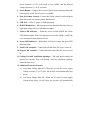
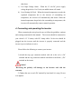
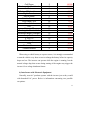
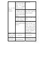
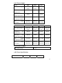
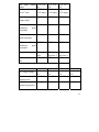
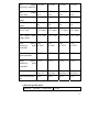
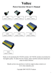
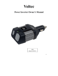
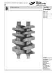
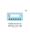
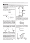
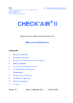
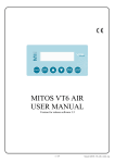
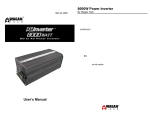
Voltec
Power Inverter Owner’s Manual
200W
(Model #: 10-00476)
1000W
(Model #: 10-00480)
400W
(Model #: 10-00477)
1500W
(Model #: 10-00481)
750W
(Model #: 10-00479)
2000W
(Model #: 10-00482)
3000W
(Model #: 10-00483)
1
Thank you for purchasing this VOLTEC product. All VOLTEC
products are produced to the highest quality. To reduce the risk
of injury, please read this instruction manual and retain for
future reference.
Should you have any questions or need any support, please
contact us at www.voltec-industries.com
Copyright 2009 VOLTEC Products
CONTENTS
1.
2.
3.
4.
5.
6.
7.
Introduction............................................................2
Safety Information.................................................3
Features...................................................................5
Connecting/Operating the inverter ......................8
Troubleshooting ...................................................10
Specifications........................................................14
Error Codes ..........................................................18
1. Introduction
Thank you for purchasing this VOLTEC power inverter, a high
performance solution to using household power while on the road. Connected
to a 12V volt outlet, the inverter efficiently and reliably supplies 115V/60Hz
AC power for a wide variety of loads, such as TV sets, gaming systems, cell
2
phones and portable entertainment devices. Our line of power inverters are
designed to meet and exceed your quality expectations with ETL certification.
With proper care and appropriate usage, this inverter will give you years of
dependable service in your car, truck, RV and boat.
2. Important Safety Information
For safe and optimum performance, the inverter must be installed and
used properly. Carefully read and follow the guidelines below:
Warning
The inverter produces the same AC power as normal household outlets and
thus has a shock hazard. Please do not allow children to use the inverters
unattended
•
Be sure that there is at least 2 in (5cm) of unobstructed air space
around the entire surface (top and sides) of the inverter at all times.
During use, do not place materials that could be damaged by heat
•
near the unit.
Do not operate the unit near flammable fumes or gases, such as near
propane tanks
•
Do not operate the unit in an enclosed area that contains lead-acid
batteries. This type of battery emits explosive hydrogen gas which
can be ignited by spark.
•
Connect AC devices before DC ones or the components built into
the inverter can become energized producing an electrical shock
hazard.
•
Do not connect the unit to live AC power circuits or there would be
3
damage to the inverter.
•
Connect the unit to only to 12V DC power supplies (6V is too low,
and 24V will damage the unit).
•
Do not insert any foreign objects into the unit outlets, vents or fan
openings.
•
Do not expose the unit to rain, water or any other liquid.
•
Do not connect the unit to any utility power distribution systems or
branch circuits.
•
Do not use the inverter in temperatures over 104(40 ) or under
32(0 ).
Caution
Do not use the unit on the following items:
y
Small nickel-cadmium battery-operated appliances such as flashlights,
razors and nightlights
y
Battery chargers for battery packs used in hand power tool that have a
warning label indicating dangerous voltages are present at the battery
terminals.
Caution – 2000W and 3000W
When using ABOVE 1000W, please make sure you use the same standard
cable kits and same standard battery or battery kits. Failure to do so will
damage the inverter.
Failure to follow these safety guidelines may result in personal injury
and/or the damage to the unit. It may also void the warranty.
4
3. Features
a) LED Indicator Models –200W, 400W and 750W
Fig. 1: DC Input Panel
1 Black terminal – negative DC power flow
2 Cooling Fan and Ventilation Openings - protects the inverter from
over-heating.
3 Red terminal - positive DC power flow
Fig. 2: Indicators
4 Green LED Indicator – indicates the inverter has power.
5 Red LED Indicator— warns that the inverter has
shut down due to low/high input voltage
6 Power Button — press to activate the unit
Fig.3: AC Outlet Panel
7 AC Outlets - receptacles for 120V AC
products with a total continuous power equal to
the wattage (W) of your inverter.
8 USB Port - Offer 5V power for USB
equipment.
9 Ventilation Openings – never cover the ventilation
openings.
5
Fig.4: Wiring
10 DC Cable with Clips—Connect the
red clip to the positive terminal of the
battery, and the black to the negative.
b) Digital Display Models –
1000W, 1500W and 2000W models
Figure 1
1. AC Outlets— receptacles for 120V AC products with a total continuous
power equal to the wattage (W) of your inverter.
2. Digital Readout—it indicates the power and DC voltages. The allowed
6
power tolerance is 15% (with loads of over 200W), and the allowed
voltage tolerance is +/-0.2V (no load).
3. Power Button— Connect the inverter to the DC power and press down the
button power switch, the AC power is available.
4. Port for Remote Control—Connect the remote control switch and press
down the switch, the remote control function acts.
5. USB Port— Offer 5V power to USB equipment.
6. Red LED Indicator— When the inverter has shut down because of low or
high input voltage, the red LED indicator lights.
7. Yellow LED Indicator — When the power exceeds 1000W, the yellow
LED indicator lights. When AC output power exceeds 1200W+/-100W, the
over current protection function will act.
8. Green LED Indicator— When there is DC power input, the green LED
indicator lights.
9. Positive DC terminal— Connect the red end of the DC power cord to it.
10. Negative DC terminal— Connect the black end of the DC power cord to
it.
11. Cooling Fan and Ventilation Openings— The high speed cooling fan
protects the inverter from over-heating. And the ventilation openings
should be kept clear!
12. Additional Protective Features
a) Over Input Voltage Shut Off - When the 12 volt DC power supply
voltage exceeds 15.5±0.5 volts, the inverter will automatically shut
down.
b) Low Input Voltage Shut Off - When the 12 volt DC power supply
voltage drops below 10.5±0.3volts, the inverter will automatically
7
shut down.
c) Low Input Voltage Alarm - When the 12 volt DC power supply
voltage drops below 11±0.3volts, an audible alarm will sound.
d) Over Heating Self-lock - When the internal temperature exceeds the
regulated temperature due to the increase of surrounding air
temperature, the inverter will automatically shut down. When the
internal temperature drops below the surrounding air temperature, the
inverter will automatically return to normal operation.
4. Connecting and operating the inverter
When connecting the unit, please be sure to follow the guideline, cautions
and warnings mentioned in this manual. The inverter should be connected to
your vehicle’s 12 V battery with DC clamp cables. No devices should be
plugged into the inverter until the inverter is properly connected and the
inverter’s power indicator is active.
Please follow the following to connect your inverter:
1) Attach the ring type connector marked with red to the red (+) DC
terminal and the ring connector marked with black to the black (-) DC
terminal on the inerter.
Caution!
Reversing the polarity will damage to the inverter and void the
warranty.
2) Tighten the nut on each DC terminal by hand until it is snug. Do not
over-tighten.
8
3) Attach the black (-) clip to the black (-) battery terminal.
4) Attach the red (+) clip to the red (+) battery terminal. Make sure both
clips are securely connected to the battery terminals, as a loose
connection will cause the voltage to drop and may cause the cables to
overheat, resulting in equipment damage or fire.
5) Turn on the inverter.
6) Plug the AC product(s) you wish to operate into the AC outlet(s) and
switch them on, one at a time.
Caution!
If there are one more AC products connecting to the inverter, turn
on the lager power product first.
7) If the Wattage draw of your devices exceeds the inverter’s capacity,
the unit will shut down and the indicator light will flash.
8) When the power inverter is not in use, disconnect the DC cable clips
from the battery to prevent unintended battery discharge.
Caution
As the battery is used, its voltage begins to fall. When the inverter senses
that the voltage at its DC input has dropped to the range of 10.7~11.3V DC, an
audible alarm sounds. This allows time for computers or other sensitive
devices to be shut down. If the audible alarm is ignored, the inverter will
automatically shut down when the voltage dropped to the range of 10.2~10.8V
DC, preventing the battery from being over-discharged. Turn off any devices
that the inverter is powering. When input voltage rose to 11.7V~12.3V DC,
9
inverter restores normal. Although the inverter incorporates protection against
over-voltage, if may still be damaged if the input voltage exceeds 16 volts.
Caution!
Most vehicle batteries are designed to provide short period of very high
current for starting the engine. They are not designed for a constant “deep
discharge”. Constantly operating the unit from a vehicle battery until the low
voltage shut off will affect the life of the battery. If you are operating electrical
products for extended periods of time, you should consider connecting the unit
to a separate deep discharge battery.
5. Troubleshooting
a) Battery Operating Time
Operating time will vary depending on the charge level of the battery, its
capacity and the power level drawn by the particular AC load. Below is a list
of common appliances and their estimated consumption:
Appliance Power
Appliances
Consumption
(Watts)
100W Inverter
100
Printer
40
Small Scanner
40
13" TV
80
Game Console (PS2, X Box)
80
9" Electric Fan
70
Personal DVD Players
15
Avg Life on Std
Car Battery
4.80
12.00
12.00
6.00
6.00
6.86
32.00
10
Cell Phone
Rechargeable Toothbrush
iPod
Wireless/BT Headphones
Digital Camera
AM/FM Radio
Sattelite Receiver
DVD Player/ VCR
Electric Knife
PSP
Nintendo DS
Rechargable Electric Knife
Household Battery Chargers
2 way Radios
5" LCD TV
BlackBerry
PDA
Wireless Mouse
Cordless Shaver
3
2
2
5
2
5
25
35
85
16
12
10
15
10
10
5
5
2
5
160.00
240.00
240.00
96.00
240.00
96.00
19.20
13.71
5.65
30.00
40.00
48.00
32.00
48.00
48.00
96.00
96.00
240.00
96.00
When using a vehicle battery as a power source, it is strongly recommended
to start the vehicle every hour or two to recharge the battery before its capacity
drops too low. The inverter can operate while the engine is running, but the
normal voltage drop that occurs during starting of the engine may trigger the
inverter’s low voltage shutdown feature.
b) Interference with Electronic Equipment
Generally, most AC products operate with the inverter just as they would
with household AC power. Below is information concerning two possible
exceptions:
11
1) Buzzing and in audio systems and radios
Some stereo systems and AM-FM radios have inadequate internal power
supply filtering and “buzz” slightly when powered by the inverter. Generally,
the only solution is an audio product with a higher quality filter.
2) Television interference
The inverter is shielded to minimize its interference with TV signals.
However, with weak TV signals interference may be visible in the form of
lines scrolling across the screen. The following should minimize or eliminate
the problem:
z
Increase the distance between the inverter and the TV, antenna and
cables.
z
Adjust the orientation of the inverter television, antenna and cables.
z
Maximize TV signal strength by using a better antenna and use
shielded antenna cable where possible.
c) Reference Chart
PROBLEM
No
power,
indicator.
CAUSE
SOLUTION
Battery is defective
Replace battery
Blown fuse
Check and replace fuse
Lose cable connections
Check the connection to the
no
battery. Tighten as required.
12
AC products connected are Reduce load.
rated at more than the
Wattage
inverter;
The
red
load
of
the
overload
LED shutdown has occurred.
indicator
AC products at less than Use a product with starting
illuminates.
the Wattage load of the surge
power
within
the
inverter, but high starting inverter’s capability.
surge has caused overload
shutdown.
The voltage input from the Charge the power source
DC power source is too battery
low (alarm is sounding).
Inverter is overheated due Unplug inverter from DC
to poor ventilation and has socket and allow to be
shut down.
cooled
for
15
minutes.
Remove objects covering
unit. Move the inverter to a
cooler place. Reduce load if
continuous
operation
is
required. Restart.
Inverter
runs
small loads but Low voltage battery
Charge the battery
not large ones.
Water entered
Disconnect the inverter and
Water entered the unit
wipe immediately with a dry
13
cloth, or permanent damage
can occur.
Low voltage shutdown or Allow unit to cool. Improve
thermal
Alarm
shutdown
has air circulation around unit.
is occurred.
Locate unit to a cooler
sounding
environment. Reduce load if
continuous
operation
is
required.
Standard
Inverter’s
“average-reading”
Measured
“modified
sine
AC wave” output requires “true
voltmeter used to measure RMS” voltmeter for accurate
inverter output is output voltage, resulting in measurements.
too low
an apparent reading 5 to
15V too low.
Battery voltage is too low
AC
product
Recharge battery
power Use a larger battery to make
consumption is higher than up
Battery run time
is
less
expected
than
for
increased
rated.
requirement.
Battery is old or defective.
Replace battery
Battery
is
not
properly charged.
power
being Some chargers are not able
to fully recharge a battery.
Make
sure
you
use
a
powerful charger.
6. Specifications
14
a) AC Power Output
Model
200W
400W
750W
125V AC
(104V)
125V AC
(104V)
125V AC
(104V)
AC
200W
400W
750W
Maximum
AC
output surge power
500W
600W
800W
AC
output
frequency(nominal)
59~61Hz
59~61Hz
59~61Hz
AC
waveform
Modified
sine wave
Modified
sine wave
Modified
sine wave
1000W
1500W
2000W
3000W
AC output voltage
125V AC
(104V)
125V AC
(104V)
125V AC
(104V)
125V AC
(104V)
Continuous
output power
AC
1000W
1500W
2000W
3000W
Maximum
AC
output surge power
2000W
3000W
4000W
6000W
AC
output
frequency(nominal)
59~61Hz
59~61Hz
59~61Hz
59~61Hz
AC
waveform
Modified
sine wave
Modified
sine wave
Modified
sine wave
Modified
sine wave
AC output voltage
Continuous
output power
output
Model
output
b) USB Power Output
DC output voltage
5V DC
c) DC Power Specifications
Model
200W
400W
750W
15
DC input voltage
range
Battery drain with
no AC load
11.0~15.0V
DC
11.0~15.0V
DC
11.0~14.5V
DC
0.35A (at a 0. 5A (at a 0.5A (at a
12V input) 12V input) 12V input)
Low battery alarm 11.0V
trigger point
11.0V
11.0V
Low
shutdown
(nominal)
10.5V
110.5V
battery 10.5V
point
Low battery resume
point (nominal)
High
shutdown
(nominal)
12.0V
battery 15.5V
point
fuse
Efficiency(maximu
m)
Model
AC output voltage
25A
fuse
85%
15.5V
15.5V
mini 25A mini 25A mini
slip fuse×2 slip fuse×4
85%
85%
1000W
1500W
2000W
3000W
105V~125V
AC
105V~125V
AC
105V~125V
DC
105V~125V
DC
1500W
2000W
3000W
3000W
4000W
6000W
Maximum
AC 1000W
output power
Maximum
AC 2000W
output surge power
16
AC
output 59~61Hz
frequency (nominal)
59~61Hz
59~61Hz
59~61Hz
AC
output
waveform
DC output voltage
range
DC input voltage
range
Battery drain with
no AC load
modified sine
wave
modified sine
wave
modified sine
wave
modified sine
wave
5V DC
5V DC
5V DC
5V DC
12.8~13.2V
DC
12.8~13.2V
DC
12.8~13.2V
DC
12.8~13.2V
DC
0.6A (at a 0. 6A (at a 1 A (at a 1 A (at a
12V input) 12V input) 12V input) 12V input)
Low battery alarm 11.0.3VDC
trigger point
11.0.3VDC
11.0.3VDC
11.0.3VDC
Low
shutdown
(nominal)
10.5
0.3VDC
10.5
0.3VDC
10.5
0.3VDC
Low battery resume 12.OV
point (nominal)
12.OV
12.OV
12.OV
High
shutdown
(nominal)
15.5V
15.5V
15.5V
battery 10.5
point 0.3VDC
battery 15.5V
point
fuse
Efficiency(maximu
m)
25A mini 25A mini 25A mini 25A mini
fuse X 5
slip fuse×7 slip fuse×10 slip fuse×10
85%
85%
85%
85%
c) Physical specifications
Ambient
operating
temperature 32~104
17
range
(0 ~40 )
7. Error Codes
OLP – Overload Protection
OPP – Short Circuit Protection
OUP – Over Voltage Protection
LUP – Low Voltage Protection
OCP – Over Temperature Protection
18