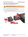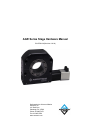
1
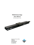
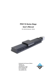
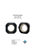
AGR Series Stage Hardware Manual
P/N: EDS139 (Revision 1.03.00)
Dedicated to the Science of Motion
Aerotech, Inc.
101 Zeta Drive,
Pittsburgh, PA, 15238
Phone: 412-963-7470
Fax: 412-963-7459
www.aerotech.com
Technical Support
Go to www.aerotech.com/service-and-support.aspx for information and support about your Aerotech
products. The website provides downloadable resources (such as up-to-date software, product manuals,
and Help files), training schedules, and PC-to-PC remote technical support. You can also complete Product
Return (RMA) forms and get information about repairs and spare or replacement parts.
For immediate help, contact a service office or your sales representative. Have your customer order number
available before you call or include it in your email.
United States
(World Headquarters)
Phone: (412) 967-6440
Fax: (412) 967-6870
Email: [email protected]
101 Zeta Drive
Pittsburgh, PA 15238
www.aerotech.com
United Kingdom
Phone: +44 118 940 9400
Fax: +44 118 940 9401
Email: [email protected]
Japan
Phone: +81(0)47-489-1742
Fax: +81(0)47-489-1743
Email: [email protected]
Germany
Phone: +49 911 967 9370
Fax: +49 911 967 93720
Email: [email protected]
China
Phone: +852-3793-3488
Email: [email protected]
France
Phone: +33-238970830
Email: [email protected]
Taiwan
Phone: +886 (0)2-8502-6651
Email: [email protected]
N O T E : Aerotech continually improves its product offerings; listed options may be superseded at any
time. Refer to the most recent edition of the Aerotech Motion Control Product Guide for the most current
product information at www.aerotech.com.
N O T E : All drawings and illustrations are for reference only and were complete and accurate as of this
manual’s release. The most recent system drawings and schematics can be found on your software CD
ROM or on www.aerotech.com.
N O T E : Read this manual in its entirety before installing, operating, or servicing this product. If you do
not understand the information contained herein, contact an Aerotech representative before proceeding.
Strictly adhere to the statements given in this section and other handling, use, and operational information
given throughout the manual to avoid injury to you and damage to the equipment.
N O T E : This product is intended for light industrial manufacturing or laboratory use.
This manual contains proprietary information and may not be reproduced, disclosed, or used in whole or in
part without the express written permission of Aerotech, Inc. Product names mentioned herein are used for
identification purposes only and may be trademarks of their respective companies.
Copyright © 2009 - 2013 Aerotech, Inc. All rights reserved.
AGR Series Stage Hardware Manual
Table of Contents
Table of Contents
Table of Contents
List of Figures
List of Tables
iii
iv
v
Chapter 1: Overview
1
1.1. Standard Features
1.2. Optional Features
1.2.1. Limited Travel Option
1.2.2. Motor Options
1.2.2.1. Motor Orientation and Location
1.2.3. Brake Option
1.2.4. Encoder Option
1.2.5. Seal Option
1.2.6. Accessories
1.3. Model Numbers
1.4. Dimensions
1.5. Safety Procedures and Warnings
1.6. EC Declaration of Incorporation
Chapter 2: Installation
2.1. Unpacking and Handling the Stage
2.2. Preparing the Mounting Surface
2.3. Securing the Stage to the Mounting Surface
2.4. Motor Installation
2.5. Attaching the Payload to the Stage
2.6. Electrical Installation
Chapter 3: Operating Specifications
3.1. Environmental Specifications
3.2. Basic Specifications
3.3. Moment Load Capacity
3.4. Standard Motor Wiring
3.4.1. Motor Wiring for the AGR200
3.4.2. Position Encoder Wiring
3.5. Limit Switch Wiring
3.5.1. Limit Switch Operation
Chapter 4: Maintenance
4.1. Service and Inspection Schedule
4.2. Cleaning and Lubrication
4.2.1. Recommended Cleaning Solvents
4.2.2. Lubrication Procedure
4.3. Troubleshooting
2
4
4
4
5
6
6
7
8
9
11
16
17
19
19
20
21
21
22
22
23
23
24
31
32
34
35
36
36
37
37
38
38
38
39
Appendix A: Stepper Motor Removal
41
Appendix B: Warranty and Field Service
43
Appendix C: Revision History
45
Index
47
www.aerotech.com
iii
Table of Contents
AGR Series Stage Hardware Manual
List of Figures
Figure 1-1:
Figure 1-2:
Figure 1-3:
Figure 1-4:
Figure 1-5:
Figure 1-6:
Figure 1-7:
Figure 1-8:
Figure 1-9:
Figure 1-10:
Figure 1-11:
Figure 1-12:
Figure 2-1:
Figure 2-2:
Figure 3-1:
Figure 3-2:
Figure 4-1:
Figure A-1:
iv
Standard AGR Rotary Stages
AGR Rotary Stage Showing Standard Features
AGR Rotary Stage Without Motor Option
AGR Rotary Stage Motor Locations
AGR Rotary Stage Encoder Option
AGR Rotary Stage Seal Option
AGR Rotary Stage Accessories
AGR50 Dimensions
AGR75 Dimensions
AGR100 Dimensions
AGR150 Dimensions
AGR200 Dimensions
Results of Flat Versus Non-Flat Mounting
View of an AGR Stage Showing Mounting Holes
AGR Axial and Radial Cantilevered Load Capability
Limit Switch Wiring
View of the Current Draw of a Typical AGR Stage Before and After Lubrication
Stepper Motor Removal
1
2
4
5
6
7
8
11
12
13
14
15
20
21
31
36
38
41
www.aerotech.com
AGR Series Stage Hardware Manual
Table of Contents
List of Tables
Table 1-1:
Table 3-1:
Table 3-2:
Table 3-3:
Table 3-4:
Table 3-5:
Table 3-6:
Table 3-7:
Table 3-8:
Table 3-9:
310SM)
Table 3-10:
Table 3-11:
Table 3-12:
Table 3-13:
Table 3-14:
Table 3-15:
Table 3-16:
Table 3-17:
Table 3-18:
Table 3-19:
Table 4-1:
Model Numbering System
Environmental Specifications
AGR Series Mechanical Specifications
Electrical Specifications
Recommended Controller
BMS35 and BMS60 Motor Specifications (AGR50/75 - BMS35, AGR100/150 - BMS60)
BMS280 Motor Specifications (AGR200)
BM22 and BM75 Motor Specifications (AGR50/75 - BM22, AGR100/150 - BM75)
BM250 Motor Specifications (AGR200)
Stepper Motor Specifications (AGR50/75 - NEMA17, AGR100/150 - 50SM, AGR200 High Power D-Style Motor Connector Pin Assignment
High Power D-Style Mating Connector
Motor Feedback Connector Pin Assignment (D-Style Connector)
Mating Connector for the Motor Feedback Connector
Feedback Connector Pin Assignment (MS3101A20-29P)
Motor Power Connector Pin Assignment (MS3101A18-10P)
Position Encoder Connector Pin Assignment
Position Encoder Mating Connector
Limit Switch Connector Pin Assignment
Limit Switch Mating Connector
Troubleshooting
www.aerotech.com
9
23
24
25
25
26
27
28
29
30
32
33
33
33
34
34
35
35
36
36
39
v
Table of Contents
vi
AGR Series Stage Hardware Manual
www.aerotech.com
AGR Series Stage Hardware Manual
Overview
Chapter 1: Overview
AGR series motorized rotary stages provide significant improvements in speed, load capacity, and long-term
positioning performance over previous generations of worm-gear-drive stages. AGR series stages address a
wide range of applications for general purpose positioning in laboratory and industrial uses.
The AGR series of worm gear driven rotary stages are available in both continuous and limited travel
versions. There are five members of the product family whose apertures range from 50 mm to 200 mm in
diameter.
Construction Features
The addition of a larger clear aperture is a key enhancement over previous generations of worm-gear-driven
stages. This feature allows the AGR series to address applications requiring a through-hole or
accommodations to mount an optic, including articulation of beam polarizing lenses, through-holes for
cabling and/or air lines, or vision/camera/inspection applications.
The AGR stage base is fabricated from an aluminum alloy that offers significant weight savings in multi-axis
arrangements and other weight critical applications, while providing high structural stiffness and long-term
stability.
Each stage is designed with two high-precision angular contact bearings with optimal spacing to provide
excellent error motions coupled with high load capacities in a small, compact package.
Flexible Options
Options include flexible motor selections as well as a direct encoder mounted to the stage shaft for
outstanding repeatability and to virtually eliminate hysteresis and backlash. Vacuum-compatible versions
(for use in pressures as low as 10-6 torr) are also available.
Motor and Drives
Standard AGR stage configurations feature Aerotech’s brushless servomotors. However, all AGR stages
can be outfitted with stepper or DC brush motors. A full range of matching drives and controls are available
for a complete single-source solution.
Figure 1-1:
Standard AGR Rotary Stages
N O T E : This product is intended for light industrial manufacturing or laboratory use.
www.aerotech.com
Chapter 1
1
Overview
AGR Series Stage Hardware Manual
1.1. Standard Features
All AGR rotary stages are designed around exceptionally large apertures while maintaining a small footprint.
The height of the stage is governed by the NEMA frame size of the mounted motor, minimizing the overall
height of the product. Each AGR rotary stage is designed to be mounted with either a vertical or horizontal
axis of rotation. These two mounting surfaces as well as the standard AGR rotary stage features are shown
in Figure 1-2.
The AGR series of rotary stages are available with one of Aerotech’s high performance brushless servo
motors mounted with motor cabling oriented as shown in Figure 1-2. Coupling access is provided allowing for
easy maintenance.
GREASE FITTING FOR
GEAR LUBRICATION
PRIMARY MOUNTING
SURFACE
ACCESS HOLES FOR
WORM LUBRICATION
LIMIT FLAG
LIMIT SENSOR
ACCESS HOLE FOR
GEAR LUBRICATION
COUPLING ACCESS HOLES
MOTOR
SECONDARY MOUNTING
SURFACE
LIMIT WIRING
Figure 1-2:
2
AGR Rotary Stage Showing Standard Features
Chapter 1
www.aerotech.com
AGR Series Stage Hardware Manual
Overview
A precision ground worm shaft with matching gear makes up the drive mechanism in all AGR rotary stages.
The gear mesh is precisely set at the factory in such a way as to minimize wear characteristics, greatly
improving stage life while maintaining stage performance even over a large temperature range. The precision
ground worm drive mechanism also creates outstanding angular positioning and velocity control. This is
especially useful in scanning applications where torque ripple cannot be tolerated. Other added benefits of
the worm drive are high levels of torque output and natural braking ability.
The drive mechanism is lubricated with a high quality grease containing extreme pressure and anti-wear
additives instead of the messy oil lube used traditionally. Designed around this grease, the AGR series of
rotary stages does not require oil seals, eliminating the high levels of friction generated torque. This
increases available torque for the application and reduces the required motor size. Lubrication is easily
maintained on the fly with access ports on the side of the rotary table. Refer to Chapter 4: Maintenance for
maintenance schedules and procedures.
The rotary stage shaft is supported by a pair of precision-ground angular contact bearings which are
preloaded to ensure superior stiffness, load carrying capacity and minimal tilt errors. Stages in the AGR
product family are designed to handle significant axial, radial, and moment loads. The combination of quality
gear components and angular contact bearing set provide superior stage accuracy and repeatability.
Other standard design features include the optical home limit switch through a 9 pin connector. The home
limit switch wiring passes through the top cover plate on the motor side and into the connector where it is
then attached to the motor wiring. Refer to Section 3.5.1. for a description of home limit switch operation and
wiring. The electrical wiring from the motor and encoder to the connectorized ports on the motor case is
contained within the rear motor housing and has been completed at the factory. The motor cables and limit
cable convey motor power, encoder feedback, and home limit switch signals to an appropriate hardware
device (e.g. axis controller or amplifier). Refer to Section 3.4. for standard motor wiring and connector pin
outputs.
www.aerotech.com
Chapter 1
3
Overview
AGR Series Stage Hardware Manual
1.2. Optional Features
1.2.1. Limited Travel Option
AGR rotary stages are available in limited travel models. The travel range of these models is between 15°
and 270° in 15° increments. Each option is proved with 4° of over-travel as standard. Custom travels are
handled as part of Aerotech's engineering specificaion (ES) system.
The limit output can be selected to be either normally open or normally closed.
Limit wiring can be provided with either a 9-pin “D” connector or flying leads.
1.2.2. Motor Options
Several motor offerings for the AGR series of rotary stages are available: Brushless/Slotless, Brushless,
and Stepper. The AGR series is also available without an attached motor. The required motor frame size per
product model is shown in Section 3.2.
MOTOR COUPLING
Figure 1-3:
4
LIMIT WIRING
AGR Rotary Stage Without Motor Option
Chapter 1
www.aerotech.com
AGR Series Stage Hardware Manual
Overview
1.2.2.1. Motor Orientation and Location
In an effort to provide the maximum flexibility to integrate the stage into higher level systems, the motor may
be mounted to the rotary stage in multiple orientations and locations. Refer to the Aerotech's online catalog
for images of the motor orientation options (-R-3 is the standard combination)
In addition, the AGR series are designed such the motor can be mounted on either side of the drive
mechanism, as shown in Figure 1-4.
-R CONFIGURATION
(STANDARD)
Figure 1-4:
www.aerotech.com
-L CONFIGURATION
AGR Rotary Stage Motor Locations
Chapter 1
5
Overview
AGR Series Stage Hardware Manual
1.2.3. Brake Option
AGR rotary stages are available with brakes integrated into the motor. Note that in two models (AGR100 and
AGR150), the brake housing extends below the stage mounting surface. In addition, the stepper motor
option for the AGR200 also extends below the mounting surface. Refer to the dimension drawings for
specific stage details (refer to Section 1.4.). The standard AGR mounting plate option (-MP) is recommended
in these cases to provide the necessary clearance for mounting the stages.
1.2.4. Encoder Option
The AGR series of rotary stages are available with direct encoders to increase stage performance. The highperformance rotary encoder is directly coupled to the payload mounting surface. This option is available in an
amplified sine or with 50X TTL output. This option increases the height of the standard model (refer to
Section 1.4.).
ENCODER ENCLOSURE
Figure 1-5:
6
AGR Rotary Stage Encoder Option
Chapter 1
www.aerotech.com
AGR Series Stage Hardware Manual
Overview
1.2.5. Seal Option
Non-contact labyrinth seals are available in all sizes of the AGR series, as shown in Figure 1-6. This option
provides protection from external contaminants while not adding any torque reducing friction. This option
increases the height of the product (refer to Section 1.4.).
SEAL ENCLOSURE
Figure 1-6:
www.aerotech.com
AGR Rotary Stage Seal Option
Chapter 1
7
Overview
AGR Series Stage Hardware Manual
1.2.6. Accessories
Two accessories are available for the AGR series of rotary stages: English/Metric table tops and a
breadboard adapter plate. An AGR100 model with both accessories is shown in Figure 1-7. The table top
provides a convenient mounting pattern with both English and metric holes. The adapter plate allows the
AGR series to mount to English or metric breadboards. These accessories increase the height of the product
(refer to Section 1.4.).
TABLETOP ACCESSORY (-TT)
BREADBOARD ADAPTER
ACCESSORY (-MP)
Figure 1-7:
8
AGR Rotary Stage Accessories
Chapter 1
www.aerotech.com
AGR Series Stage Hardware Manual
Overview
1.3. Model Numbers
N O T E : Aerotech continually improves its product offerings; listed options may be superseded at any
time. Refer to the most recent edition of the Aerotech Motion Control Product Guide for the most current
product information at www.aerotech.com.
Table 1-1:
Model Numbering System
Aperture Size
50
75
100
150
200
50 mm diameter clear aperture
75 mm diameter clear aperture
100 mm diameter clear aperture
150 mm diameter clear aperture
200 mm diameter clear aperture
Travel Options
-LIxx
XXX degrees of nominal limit travel (plus 2 degrees of overtravel per side) where XXX =
015 to 270 in 15 deg increments and 315 degrees
Limits Options
-NC-9DU
-NO-9DU
-NC-FLY
-NO-FLY
Normally-closed end of travel limit switches with 9-pin connector
Normally-open end of travel limit switches with 9-pin connector
Normally-closed end of travel limit switches with flying leads
Normally-open end of travel limit switches with flying leads
Motor and Brake Options
-NM
-SM
-BMS
-BMS-BK
-BM
No motor
Stepping motor
AGR50/75: NEMA17 stepping motor
AGR100/150: 50SMB2-HM
AGR200: 310SMB3-HM
Brushless, slotless servomotor with connectors and TTL encoder (requires motor-tocontroller cable)
AGR50/75: BMS35-A-D25-E2000H
AGR100/150: BMS60-A-D25-E2500H
AGR200: BMS280-AH-MS-E1000H
Brushless, slotless servomotor with connectors, TTL encoder, and fail-safe brake
(requires motor-to-controller cable)
AGR50/75: BMS35-A-D25-E2000H-BK
AGR100/150: BMS60-A-D25-E2500H-BK1
AGR200: BMS280-AH-MS-E1000H-BK2
Brushless servomotor with connectors and TTL encoder (requires motor-to-controller
cable)
AGR50/75: BM22-D25-E2000H
AGR100/150: BM75-D25-E2500H
AGR200: BM250-MS-E1000H
www.aerotech.com
Chapter 1
9
Overview
AGR Series Stage Hardware Manual
Motor and Brake Options (Continued)
-BM-BK
Brushless servomotor with connectors, TTL encoder, and fail-safe brake (requires motorto-controller cable)
AGR50/75: BM22-D25-E2000H-BK
AGR100/150: BM75-D25-E2500H-BK1
AGR200: BM250-MS-E1000H-BK2)
-BMS-AS
Brushless, slotless servomotor with 1000-line amplified sine encoder
AGR50/75: BMS35-A-D25-E1000ASH
AGR100/150: BMS60-A-D25-E1000ASH
AGR200: BMS280-AH-MS-E1000ASH
-BMS-AS-BK Brushless, slotless servomotor with fail-safe brake and 1000-line amplified sine encoder
AGR50/75: BMS35-A-D25-E1000ASH-BK
AGR100/150: BMS60-A-D25-E1000ASH-BK1
AGR200: BMS280-AH-MS-E1000ASH-BK2
-BM-AS
Brushless servomotor with 1000-line amplified sine encoder
AGR50/75: option not available
AGR100/150: BM75-D25-E1000ASH
AGR200: BM250-MS-E1000ASH
-BM-AS-BK
Brushless servomotor with fail-safe brake and 1000-line amplified sine encoder
AGR50/75: option not available
AGR100/150: BM75-D25-E1000ASH-BK1
AGR200: BM250-MS-E1000ASH-BK2
Motor Location
-R
-L
Motor located on right side of stage housing (standard)
Motor located on left side of stage housing (optional)
Motor Orientation
-0
-2
-3
-4
-5
No motor
Bottom cable exit
Left side cable exit (Standard)
Top cable exit
Right side cable exit
Sealing Option
-SL
Labyrinth seals supplied with product
Encoder Option
-AS
-X5
-X50
Amplfied sine output encoder (see Table 3-3 for fundamental resolution)
Square wave TTL output; X5 multiplication
Square wave TTL output; X50 multiplication
Accessories
-TTM
-TTU
-MP
Metrology
Metric tabletop
English tabletop
Universal English/Metric mounting plate
-PLOTS
Accuracy and repeatability performance plots
10
Chapter 1
www.aerotech.com
AGR Series Stage Hardware Manual
Overview
1.4. Dimensions
MOTOR
LENGTH "A"
OPTION
HEIGHT "B"
BM22
91.1
DEFAULT
50
BM22-BRAKE
128
SEAL
60
BMS35
125
ENCODER
66.4
BMS35-BRAKE
153
SEAL + ENCODER
76.4
NEMA17 STEPPER
95.3
100
25
25
8X M5X0.8
50
APERTURE
10.5
7.5
63 BC
75
10.5
4X
5.5 THRU ALL
10 TO DEPTH SHOWN
4X M4X0.7
6
4X M4X0.7
6
31
20
GREASE
FITTING
50
129.8
22
20
3
69.4
37 SQ
20
TYP
6.35 [1/4"]
SHAFT INPUT
105
2
31 SQ
120.8
12X M3X0.5
A
CW
0.5 * NOMINAL TRAVEL
15
CCW
0.5 * NOMINAL TRAVEL
6
MOTOR HIDDEN
FOR CLARITY
TABLETOP BC ORIENTATION
AT HOME LOCATION
2.
4X M5X0.8
B
75
7.5
25
10.5
-SM MOTOR OPTION MOUNTING
NOTES:
1.
TO MOUNT/DISMOUNT MOTOR,
THREAD M3 X 0.5 HEX NUTS ON/OFF
OF FIXED MOTOR STUDS AS SHOWN.
2.
CW AND CCW TRAVEL LIMITATIONS APPLY
TO -LIXXX LIMITED TRAVEL OPTION ONLY.
ORIENTATION OF TABLETOP BC AT HOME
LOCATION IS CONSISTENT FOR ALL
CONFIGURATIONS.
1.
2X STUD, M3 X 0.5
DIMENSIONS: MILLIMETERS
Figure 1-8:
www.aerotech.com
1.
2X HEX NUT, M3 X 0.5
AGR50 Dimensions
Chapter 1
11
Overview
AGR Series Stage Hardware Manual
MOTOR
LENGTH "A"
OPTION
HEIGHT "B"
BM22
91.1
DEFAULT
50
BM22-BRAKE
128
SEAL
60
BMS35
125
ENCODER
66.4
BMS35-BRAKE
153
SEAL + ENCODER
76.4
NEMA17 STEPPER
95.3
146.2
125
25
8X M5X0.8
75
APERTURE
10.5
25
7.5
85 BC
94.5
10.5
5.5 THRU ALL
4X
10 TO DEPTH SHOWN
4X M4X0.7
6
4X M4X0.7
6
20
GREASE
FITTING
50
155.2
22
20
3
82.1
46.5
TYP
37 SQ
31 SQ
20
TYP
6.35 [1/4"]
SHAFT INPUT
12.7
120.8
A
12X M3X0.5
15
CW
0.5 * NOMINAL TRAVEL
6
MOTOR HIDDEN
FOR CLARITY
CCW
0.5 * NOMINAL TRAVEL
TABLETOP BC ORIENTATION
AT HOME LOCATION
2.
4X M5X0.8
B
75
7.5
25
10.5
-SM MOTOR OPTION MOUNTING
NOTES:
1.
TO MOUNT/DISMOUNT MOTOR,
THREAD M3 X 0.5 HEX NUTS ON/OFF
OF FIXED MOTOR STUDS AS SHOWN.
2.
CW AND CCW TRAVEL LIMITATIONS APPLY
TO -LIXXX LIMITED TRAVEL OPTION ONLY.
ORIENTATION OF TABLETOP BC AT HOME
LOCATION IS CONSISTENT FOR ALL
CONFIGURATIONS.
1.
2X STUD, M3 X 0.5
1.
2X HEX NUT, M3 X 0.5
DIMENSIONS: MILLIMETERS
Figure 1-9:
12
AGR75 Dimensions
Chapter 1
www.aerotech.com
AGR Series Stage Hardware Manual
Overview
MOTOR
LENGTH "A"
OPTION
HEIGHT "B"
BM75
132.3
DEFAULT
65
BM75-BRAKE
209.5
SEAL
78
BMS60
132.3
ENCODER
81
BMS60-BRAKE
209.5
SEAL + ENCODER
94
50SMB2-HM
84.3
150
25
100
APERTURE
8X M6X1.0
17.2
9
25
112.5 BC
127
17.2
6.6 THRU ALL
4X
12.7 TO DEPTH SHOWN
4X M5X0.8
7.5
4X M5X0.8
7.5
50
GREASE
FITTING
80
190.7
50
104.9
38.1
4.5
33.4
TYP
3.2
47.1 SQ
15
6.35 [1/4"]
SHAFT INPUT
A
171.6
4X M4X0.7
8
MOTOR HIDDEN
FOR CLARITY
CW
0.5 * NOMINAL TRAVEL
CCW
0.5 * NOMINAL TRAVEL
TABLETOP BC ORIENTATION
AT HOME LOCATION
1.
4X M6X1.0
B
125
9
40
9.7
NOTE: BRAKE OPTIONS PROTRUDE
BELOW MOUNTING SURFACE
2.4
NOTES:
1.
CW AND CCW TRAVEL LIMITATIONS APPLY
TO -LIXXX LIMITED TRAVEL OPTION ONLY.
ORIENTATION OF TABLETOP BC AT HOME
LOCATION IS CONSISTENT FOR ALL
CONFIGURATIONS.
DIMENSIONS: MILLIMETERS
Figure 1-10:
www.aerotech.com
AGR100 Dimensions
Chapter 1
13
Overview
AGR Series Stage Hardware Manual
MOTOR
LENGTH "A"
OPTION
HEIGHT "B"
BM75
132.3
DEFAULT
65
BM75-BRAKE
209.5
SEAL
78
BMS60
132.3
ENCODER
81
BMS60-BRAKE
209.5
SEAL + ENCODER
94
50SMB2-HM
84.3
NOTE: CONFIGURATIONS: AGR150-SM-R-3 & AGR150-SM-L-5 ARE UNAVAILABLE
AS STANDARD CONFIGURATIONS.
222.4
200
25
150
APERTURE
9
8X M6X1.0
25
164 BC
177
17.2
17.2
6.6 THRU ALL
4X
12.7 TO DEPTH SHOWN
4X M5X0.8
7.5
4X M5X0.8
7.5
100
GREASE
FITTING
125
241.5
100
130.3
58.8
TYP
38.1
4.5
33.4
TYP
47.1 SQ
15
6.35 [1/4"]
SHAFT INPUT
A
171.6
25.4
4X M4X0.7
8
MOTOR HIDDEN
FOR CLARITY
CCW
0.5 * NOMINAL TRAVEL
CW
0.5 * NOMINAL TRAVEL
TABLETOP BC ORIENTATION
AT HOME LOCATION
1.
4X M6X1.0
B
NOTES:
1.
125
9
40
9.7
NOTE: BRAKE OPTIONS PROTRUDE
BELOW MOUNTING SURFACE
CW AND CCW TRAVEL LIMITATIONS APPLY
TO -LIXXX LIMITED TRAVEL OPTION ONLY.
ORIENTATION OF TABLETOP BC AT HOME
LOCATION IS CONSISTENT FOR ALL
CONFIGURATIONS.
DIMENSIONS: MILLIMETERS
Figure 1-11:
14
2.4
AGR150 Dimensions
Chapter 1
www.aerotech.com
AGR Series Stage Hardware Manual
Overview
LENGTH "A"
OPTION
BM250
190
DEFAULT
90
BM250-BRAKE
245.6
SEAL
107
MOTOR
HEIGHT "B"
BMS280
190
ENCODER
108.5
BMS280-BRAKE
245.6
SEAL + ENCODER
125.5
310SMB3-HM
165.4
305
250
8X M8X1.25
200
APERTURE
235
50
17
12
217 BC
9 THRU ALL
4X
15 TO DEPTH SHOWN
17
50
4X M6X1.0
9
4X M6X1.0
9
150
GREASE
FITTING
200
150
340.1
187.6
73
4
85
TYP
57.9
TYP
69.6 SQ
SHAFT INPUT
12.7 [1/2"] STANDARD
9.5 [3/8"] FOR -SM OPTION
15
14
277
A
4X M5X0.8
10
MOTOR HIDDEN
FOR CLARITY
CCW
0.5 * NOMINAL TRAVEL
CW
0.5 * NOMINAL TRAVEL
TABLETOP BC ORIENTATION
AT HOME LOCATION
1.
4X M8X1.25
B
200
12
50
0.9
17
NOTE: STEPPER MOTOR OPTION PROTRUDES
BELOW MOUNTING SURFACE
NOTES:
1.
CW AND CCW TRAVEL LIMITATIONS APPLY
TO -LIXXX LIMITED TRAVEL OPTION ONLY.
ORIENTATION OF TABLETOP BC AT HOME
LOCATION IS CONSISTENT FOR ALL
CONFIGURATIONS.
DIMENSIONS: MILLIMETERS
Figure 1-12:
www.aerotech.com
AGR200 Dimensions
Chapter 1
15
Overview
AGR Series Stage Hardware Manual
1.5. Safety Procedures and Warnings
The following statements apply wherever the Warning or Danger symbol appears within this manual. Failure
to observe these precautions could result in serious injury to those individuals performing the procedures
and/or damage to the equipment. Operators should be trained before operating this equipment and all service
and maintenance must be performed by qualified personnel.
D A N G E R : This product contains potentially lethal voltages. To reduce the possibility of
electrical shock, bodily injury or death the following precautions must be followed.
1. Access to all AGR and component parts must be restricted while connected to a power
source.
2. Do not connect or disconnect any electrical components or connecting cables while
connected to a power source.
3. Disconnect electrical power before making any mechanical adjustments or performing
maintenance.
4. Make sure AGR and all components are properly grounded in accordance with local
electrical safety requirements.
5. Operator safeguarding requirements must be addressed during final integration of the
product.
W A R N I N G : To minimize the possibility of electrical shock, bodily injury or death the
following precautions must be followed.
1. Moving parts can cause crushing or shearing injuries. Access to all stage and motor parts
must be restricted while connected to a power source.
2. Cables can pose a tripping hazard. Securely mount and position all system cables to avoid
potential hazards.
3. Do not expose the AGR to environments or conditions outside the specified range of
operating environments. Operation in conditions other than those specified can cause
damage to the equipment.
4. The AGR must be mounted securely. Improper mounting can result in injury and damage
to the equipment.
5. Use care when moving the AGR. Manually lifting or transporting the AGR can result in
injury.
6. This AGR is intended for light industrial manufacturing or laboratory use. Use of the AGR
for unintended applications can result in injury and damage to the equipment.
7. If the AGR is used in a manner not specified by the manufacturer, the protection provided
by the AGR can be impaired and result in damage, shock, injury, or death.
16
Chapter 1
www.aerotech.com
AGR Series Stage Hardware Manual
Overview
1.6. EC Declaration of Incorporation
Manufacturer: Aerotech, Inc.
101 Zeta Drive
Pittsburgh, PA 15238
USA
herewith declares that the product:
AGR Stage
is intended to be incorporated into machinery to constitute machinery covered by the Directive
2006/42/EC as amended;
does therefore not in every respect comply with the provisions of this directive;
and that the following harmonized European standards have been applied:
EN ISO 12100
Safety of machinery - Basic concepts, general principles for design
EN 60204-1
Safety of machinery - Electrical equipment of machines - Part 1: General requirements
and further more declares that
it is not allowed to put the equipment into service until the machinery into which
it is to be incorporated or of which it is to be a component has been found and
declared to be in conformity with the provisions of the Directive 2006/42/EC and
with national implementing legislation, i.e. as a whole, including the equipment
referred to in this Declaration.
Authorized Representative:
Address:
Name
Position
Location
Date
www.aerotech.com
Manfred Besold
AEROTECH GmbH
Süd-West-Park 90
D-90449 Nürnberg
/ Alex Weibel
Engineer Verifying Compliance
Pittsburgh, PA
May 14, 2013
Chapter 1
17
Overview
18
AGR Series Stage Hardware Manual
Chapter 1
www.aerotech.com
AGR Series Stage Hardware Manual
Installation
Chapter 2: Installation
This chapter describes the installation procedure for the AGR stage, including handling the stage, preparing
the mounting surface to accept the stage, securing the stage to the mounting surface, attaching the payload,
and making the electrical connections.
W A R N I N G : AGR installation must be in accordance to instructions provided by this manual
and any accompanying documentation. Failure to follow these instructions could result in injury
and damage to the equipment.
2.1. Unpacking and Handling the Stage
Carefully remove the AGR from the protective shipping container. Before operating the AGR, it is important
to let the AGR stabilize at room temperature for at least 12 hours. Allowing the AGR to stabilize to room
temperature will ensure that all of the alignments, preloads, and tolerances are the same as they were when
tested at Aerotech. Use compressed nitrogen or clean, dry, oil-less air to remove any dust or debris that has
collected during shipping. Set the AGR on a smooth, flat, and clean surface.
Each AGR has a label listing the system part number and serial number. These numbers contain information
necessary for maintaining or updating system hardware and software. Locate this label and record the
information for later reference. If any damage has occurred during shipping, report it immediately.
W A R N I N G : Make sure all moving parts are secure before moving the AGR. Unsecured
moving parts may shift and cause bodily injury.
W A R N I N G : Lift the AGR only by the base. Improper handling could adversely affect the
AGR’s performance.
www.aerotech.com
Chapter 2
19
Installation
AGR Series Stage Hardware Manual
2.2. Preparing the Mounting Surface
The mounting surface should be flat and have adequate stiffness in order to achieve the maximum
performance from the AGR. When the AGR is mounted to a non-flat surface, the stage can be distorted as
the mounting screws are tightened. This distortion will decrease the overall accuracy of the stage.
Adjustments to the mounting surface must be done before the stage is secured.
N O T E : To maintain accuracy, the mounting surface should be flat within 10 µm over the entire stage
footprint.
Figure 2-1:
Results of Flat Versus Non-Flat Mounting
N O T E : The AGR is precision machined and verified for flatness prior to product assembly at the factory.
If machining is required to achieve the desired flatness, it should be performed on the mounting surface
rather than the AGR . Shimming should be avoided if possible. If shimming is required, it should be
minimized to improve the rigidity of the system.
20
Chapter 2
www.aerotech.com
AGR Series Stage Hardware Manual
Installation
2.3. Securing the Stage to the Mounting Surface
AGR series stages have a fixed mounting pattern available to secure the stage to a mounting surface. The
counter-bored mounting holes are designed for 5 mm socket head cap screws (SHCS) for the AGR50 and
AGR75, 6 mm SHCS for the AGR100 and AGR150, and 8 mm SHCS for the AGR200.
W A R N I N G : The AGR must be mounted securely. Improper mounting can result in injury
and damage to the equipment.
AGR series stages also have a fixed mounting pattern on the side of the stage. The size of the side mounting
holes are M5 for the AGR50 and AGR75; M6 for the AGR100 and AGR150; and M8 for the AGR200.
Figure 2-2:
View of an AGR Stage Showing Mounting Holes
2.4. Motor Installation
The basic model of the AGR series of rotary stages are factory shipped with the appropriate sized motor.
When the “no motor” option has been selected or for motor service, access to the motor coupling is provided
by removing half of the split top cover that is directly above the rotary motor (refer to Figure 1-2 for locations
of the coupling access holes).
www.aerotech.com
Chapter 2
21
Installation
AGR Series Stage Hardware Manual
2.5. Attaching the Payload to the Stage
To prevent damage to payloads, test the operation of the stage before the payload is attached to the stage
table. Proceed with the electrical installation and test the motion control system in accordance with the
system documentation. Document all results for future reference. For information on electrical connections,
refer to Section 3.4. and the documentation delivered with the stage.
The payload must be flat, rigid, and comparable to the stage in quality.
2.6. Electrical Installation
W A R N I N G : Electrical installation must be performed by properly qualified personnel.
Aerotech motion control systems are adjusted at the factory for optimum performance. When the AGR is
part of a complete Aerotech motion control system, setup usually involves connecting a stage and motor
combination to the appropriate drive chassis with the cables provided. Connect the provided cables to the
feedback and motor connectors on the stage body. Labels on the system components usually indicate the
appropriate connections.
Refer to the appropriate system manuals and documentation included on the CD-ROM for additional
installation and operation information. If the system is uniquely configured, a drawing showing system
interconnects is supplied.
W A R N I N G : Applications requiring access to the stage while it is energized will require
additional grounding and safeguards. The System Integrator or qualified installer is responsible
for determining and meeting all safety and compliance requirements necessary for the
integration of this stage into the final application.
D A N G E R : Remove power before connecting or disconnecting electrical components or
cables. Failure to do so may cause electric shock.
W A R N I N G : Operator access to the base and table top must be restricted while connected
to a power source. Failure to do so may cause electric shock.
N O T E : Refer to the controller documentation to adjust servo gains for optimum velocity and position
stability.
22
Chapter 2
www.aerotech.com
AGR Series Stage Hardware Manual
Operating Specifications
Chapter 3: Operating Specifications
The surrounding environment and operating conditions can affect the performance and service life of the
stage. This chapter provides information on ideal environmental and operating conditions.
3.1. Environmental Specifications
The environmental specifications for the AGR are listed in the following table.
Table 3-1:
Environmental Specifications
Ambient
Temperature
Operating: 10° to 35° C (50° to 95° F)
The optimal operating temperature is 20° C ±2° C (68° F ±4° F). If at any time the
operating temperature deviates from 20° C degradation in performance could occur.
Contact Aerotech for information regarding your specific application and environment.
Storage: 0° to 40° C (32° to 104° F) in original shipping packaging
Operating: 20% to 60% RH
Storage: 10% to 70% RH, non-condensing in original packaging
Operating: 0 m to 2,000 m (0 ft to 6,562 ft) above sea level
Contact Aerotech if your specific application involves use above 2,000 m or below sea
level.
Use the system in a low vibration environment. Excessive floor or acoustical vibration
can affect system performance. Contact Aerotech for information regarding your
specific application.
Humidity
Altitude
Vibration
Dust Exposure
In their standard configuration the AGR stages have limited protection against airborne
particles but not water. This equates to an ingress protection rating of IP40.
With the Seal (-SL) option the AGR stages have limited protection against dust, but no
protection against water. This equates to an ingress protection rating of IP50.
Use
Indoor use only
W A R N I N G : Do not expose the AGR to environments or conditions outside the specified
range of operating environments. Operation in conditions other than those specified can cause
damage to the equipment.
www.aerotech.com
Chapter 3
23
Operating Specifications
AGR Series Stage Hardware Manual
3.2. Basic Specifications
Basic AGR series positioning stage specifications are shown below.
Table 3-2:
AGR Series Mechanical Specifications
AGR50
Travel
Frame Size
Accuracy
Repeatability
(Unidirectional)
(1)
Repeatability
(Bi-Directional)
(1)
Standard
Direct
Encoder
Standard
Direct
Encoder
Standard
Direct
Encoder
Tilt Error Motion
Axial Error Motion
Radial Error Motion
Gear Ratio
Maximum
BM/BMS
Speed (2)
SM
NEMA17
180 arc sec
AGR75
AGR100
AGR150
360° (Limited Travel Versions Available)
NEMA17
NEMA23
NEMA23
180 arc sec
120 arc sec
120 arc sec
AGR200
NEMA34
120 arc sec
20 arc sec
10 arc sec
5 arc sec
45 arc sec
8 arc sec
51:1
67:1
180°/s
180°/s
10 arc sec
5 µm
10 µm
85:1
117:1
126:1
180°/s
180°/s
120°/s
60°/s
60°/s
40°/s
40°/s
40°/s
Maximum Acceleration (3)
720°/s2
720°/s2
720°/s2
720°/s2
Aperture
50 mm
40 kg
20 kg
480°/s2
200 mm
425 kg
200 kg
Axial
Load Capacity
Radial
Moment
Maximum Torque Load to
Stage Shaft
Rotor Inertia (Unloaded)
Stage Mass
(No Motor)
Standard
Direct
Encoder
75 mm
100 mm
150 mm
100 kg
200 kg
300 kg
50 kg
100 kg
125 kg
See Moment Load Capacity: Section 3.3.
2.5 N·m
3.5 N·m
12 N·m
20 N·m
80 N·m
0.00052 kg·m2
1.9 kg
0.0013 kg·m2
2.4 kg
0.0035 kg-·m2
0.011 kg-·m2
0.076 kg-·m2
4.5 kg
6.1 kg
18.6 kg
2.5 kg
3.1 kg
5.6 kg
7.6 kg
21.7 kg
Material
Aluminum
1. Certified with each stage.
2. Maximum speed is load dependent. Contact an Aerotech Application Engineer if imbalanced loads are
present.
3. Unloaded acceleration
4. On-axis loading is listed
5. Specifications are for single-axis systems, measured 25 mm above the tabletop. Performance of multiaxis system is payload and workpoint dependent. Consult factory for multi-axis or non-standard
applications.
24
Chapter 3
www.aerotech.com
AGR Series Stage Hardware Manual
Table 3-3:
Operating Specifications
Electrical Specifications
Model
AGR50
Drive System
Feedback
Standard
Direct
Encoder
Maximum Bus Voltage
Limit Switches
Home Switch
AGR75
AGR100
AGR150
AGR200
Precision Worm-Gear with Brushless or Stepping Motor
Rotary Motor Feedback:
Rotary Motor Feedback: 2500 Lines/Rev
2000 Lines/Rev Square
Square Wave and 1000 Lines/Rev AmpliWave (BM Motor); 2500
fied Sine
Lines/Rev Square Wave
and 1000 Lines/Rev Amplified Sine (BMS Motor)
Noncontact Rotary Encoder Directly Mounted to AGR Stage Shaft
15744
18000
23600
31488
40000
Lines/Rev
Lines/Rev
Lines/Rev
Lines/Rev
Lines/Rev
80 VDC (BM Motor);
320 VDC
320 VDC (BMS Motor)
5 V, Normally Closed or Normally Open
Near Limit (for Limited Travel Stage Version)
W A R N I N G : The motor case temperature may exceed 75ºC.
Table 3-4:
Multi-Axis
Single Axis
Recommended Controller
A3200
Ensemble
Soloist
www.aerotech.com
Ndrive MP10 / Ndrive CP10 / Npaq
Ensemble MP10 / Ensemble CP10 / Epaq
Soloist MP10 / Soloist CP10
Chapter 3
25
Operating Specifications
Table 3-5:
AGR Series Stage Hardware Manual
BMS35 and BMS60 Motor Specifications (AGR50/75 - BMS35, AGR100/150 - BMS60)
Motor Model
Units
BMS35
BMS60
-A
-A
N·m (oz·in)
N·m (oz·in)
rpm
W
0.27 (38.0)
1.07 (152.0)
4,000
96
0.33 (46.2)
1.31 (184.9)
4,000
112
Vpk/krpm
12.9
19
Continuous Current, Stall (2)
Apk (Arms)
2.5 (1.7)
2.3 (1.6)
Peak Current, Stall (3)
Apk (Arms)
9.8 (6.9)
9.2 (6.5)
0.11 (15.5)
0.14 (20.1)
(4, 8)
N·m/Apk
(oz·in/Apk)
N·m/Arms
(oz·in/Arms)
0.15 (21.9)
0.20 (28.4)
0.046 (6.52)
0.050 (7.02)
5.8
1.7
8.4
1.30
340
340
°C/W
--
2.21
8
1.73
8
kg (lb)
kg·m2
(oz·in·s2)
N (lb)
N (lb)
NEMA
0.6 (1.3)
1.96x10⁻⁵
(0.0028)
45 (10)
45 (10)
17
1.1 (2.4)
1.96x10⁻⁵
(0.0028)
89 (20)
89 (20)
23
Winding Designation
Performance Specifications (1, 5)
Stall Torque, Continuous (2)
Peak Torque (3)
Rated Speed
Rated Power Output, Continuous
Electrical Specifications (5)
BEMF Constant (Line-Line, Max)
Torque Constant
Motor Constant (2, 4)
Resistance, 25°C (Line-Line)
Inductance (Line-Line)
Maximum Bus Voltage
Thermal Resistance
Number of Poles
Mechanical Specifications
Motor Weight
Rotor Moment of Inertia
Max Radial Load
Max Axial Load
Frame Size
N·m/√W
(oz·in/√W)
Ω
mH
VDC
(1) Performance is dependent upon heat sink configuration, system cooling conditions, and ambient temperature
(2) Values shown @ 75°C rise above a 25 °C ambient temperature, with motor mounted to the specified aluminum heat sink
(3) Peak force assumes correct rms current; consult Aerotech.
(4) Force constant and motor constant specified at stall.
(5) All performance and electrical specifications +/- 10%
(6) Maximum winding temperature is 100 °C (Thermistor trips at 100°C)
(7) Ambient operating temperature range: 0 °C - 25 °C, consult Aerotech for performance in elevated ambient temperatures
(8) All Aerotech amplifiers are rated Apk ; use force constant in N / Apk when sizing
W A R N I N G : The motor case temperature may exceed 75ºC.
26
Chapter 3
www.aerotech.com
AGR Series Stage Hardware Manual
Table 3-6:
Operating Specifications
BMS280 Motor Specifications (AGR200)
Motor Model
Winding Designation
Performance Specifications (1, 5)
Stall Torque, Continuous (2)
Peak Torque (3)
Rated Speed
Rated Power Output, Continuous
Electrical Specifications (5)
Units
BMS280
-A
N·m (oz·in)
N·m (oz·in)
rpm
W
1.60 (227.0)
6.41 (908.0)
3,000
381
Vpk/krpm
57
Continuous Current, Stall (2)
Apk (Arms)
3.8 (2.7)
Peak Current, Stall (3)
Apk (Arms)
15.2 (10.7)
N·m/Apk
(oz·in/Apk)
0.42
(59.7)
N·m/Arms
(oz·in/Arms)
0.60
(84.5)
N·m/√W
(oz·in/√W)
Ω
mH
VDC
0.179
(25.34)
5.7
1.10
°C/W
--
0.93
14
kg (lb)
kg·m2
(oz·in·s2)
N (lb)
N (lb)
NEMA
3.60 (7.9)
4.66x10⁻⁴
(0.0660)
178 (40)
89 (20)
34
BEMF Constant (Line-Line, Max)
Torque Constant (4, 8)
Motor Constant (2, 4)
Resistance, 25°C (Line-Line)
Inductance (Line-Line)
Maximum Bus Voltage
Thermal Resistance
Number of Poles
Mechanical Specifications
Motor Weight
Rotor Moment of Inertia
Max Radial Load
Max Axial Load
Frame Size
340
(1) Performance is dependent upon heat sink configuration, system cooling conditions, and ambient temperature
(2) Values shown @ 75°C rise above a 25 °C ambient temperature, with motor mounted to the specified aluminum heat sink
(3) Peak force assumes correct rms current; consult Aerotech.
(4) Force constant and motor constant specified at stall.
(5) All performance and electrical specifications +/- 10%
(6) Maximum winding temperature is 100 °C (Thermistor trips at 100°C)
(7) Ambient operating temperature range: 0 °C - 25 °C, consult Aerotech for performance in elevated ambient temperatures
(8) All Aerotech amplifiers are rated Apk ; use force constant in N / Apk when sizing
W A R N I N G : The motor case temperature may exceed 75ºC.
www.aerotech.com
Chapter 3
27
Operating Specifications
Table 3-7:
AGR Series Stage Hardware Manual
BM22 and BM75 Motor Specifications (AGR50/75 - BM22, AGR100/150 - BM75)
Motor Model
Units
BM22
BM75
N·m (oz·in)
N·m (oz·in)
rpm
W
0.16 (22.5)
0.48 (68.0)
3,000
50
0.55 (78.3)
1.4 (196)
4,000
207
Vpk/krpm
3.9
9
Continuous Current, Stall (2,8)
Apk (Arms)
4.9 (3.5)
10.0 (7.1)
Peak Current, Stall (3)
Apk (Arms)
14.7 (10.4)
25.0 (17.7)
N·m/Apk (oz·in/Apk)
0.032
(4.5)
0.06
(7.8)
N·m/(Arms
(oz·in/(Arms)
0.045
(6.4)
0.08
(11.1)
N·m/√W
(oz·in/√W)
Ω
mH
VDC
0.038
(5.37)
0.67
0.73
0.052
(7.33)
1.0
0.80
80
340
°C/W
--
6.26
8
1.14
8
kg (lb)
kg·m2
(oz·in·s2)
N (lb)
N (lb)
NEMA
0.4 (0.88)
2.00x10⁻⁶
(0.00028)
78 (18)
39 (9)
17
1.1 (2.42)
5.20x10⁻⁶
(0.0007)
89 (20)
89 (20)
23
Performance Specifications (1,5)
Stall Torque, Continuous (2,8)
Peak Torque(3)
Rated Speed
Rated Power Output, Continuous
Electrical Specifications(5)
BEMF Constant (Line-Line, Max)
Torque Constant (4,9)
Motor Constant (2,4)
Resistance, 25°C (Line-Line)
Inductance (Line-Line)
Maximum Bus Voltage
Thermal Resistance
Number of Poles
Mechanical Specifications
Motor Weight
Rotor Moment of Inertia
Max Radial Load
Max Axial Load
Frame Size
(1) Performance is dependent upon heat sink configuration, system cooling conditions, and ambient temperature
(2) Values shown @ 130°C rise above a 25 °C ambient temperature, with motor mounted to the specified aluminum heat sink
(3) Peak force assumes correct rms current; consult Aerotech.
(4) Force constant and motor constant specified at stall.
(5) All performance and electrical specifications +/- 10%
(6) Maximum winding temperature is 155 °C
(7) Ambient operating temperature range: 0 °C - 25 °C, consult Aerotech for performance in elevated ambient temperatures
(8) De-rate continuous torque and continuous current by 10 percent when using an encoder
(9) All Aerotech amplifiers are rated Apk ; use force constant in N / Apk when sizing
W A R N I N G : The motor case temperature may exceed 75ºC.
28
Chapter 3
www.aerotech.com
AGR Series Stage Hardware Manual
Table 3-8:
Operating Specifications
BM250 Motor Specifications (AGR200)
Motor Model
Units
BM250
N·m (oz·in)
N·m (oz·in)
rpm
W
2.0 (285)
5.0 (712)
4,000
671
Vpk/krpm
28
Continuous Current, Stall (2,8)
Apk (Arms)
10.5 (7.4)
Peak Current, Stall (3)
Apk (Arms)
26.3 (18.6)
N·m/Apk
(oz·in/Apk)
0.19
(27.1)
N·m/Arms
(oz·in/Arms)
0.27
(38.4)
N·m/√W
(oz·in/√W)
Ω
mH
VDC
0.171
(24.24)
1.1
1.30
°C/W
--
0.94
8
kg (lb)
kg·m2
(oz·in·s2)
N (lb)
N (lb)
NEMA
3.6 (7.92)
7.85x10⁻⁵
(0.0111)
178 (40)
89 (20)
34
Performance Specifications (1,5)
Stall Torque, Continuous(2,8)
Peak Torque (3)
Rated Speed
Rated Power Output, Continuous
Electrical Specifications (5)
BEMF Constant (Line-Line, Max)
Torque Constant (4,9)
Motor Constant (2,4)
Resistance, 25°C (Line-Line)
Inductance (Line-Line)
Maximum Bus Voltage
Thermal Resistance
Number of Poles
Mechanical Specifications
Motor Weight
Rotor Moment of Inertia
Max Radial Load
Max Axial Load
Frame Size
340
(1) Performance is dependent upon heat sink configuration, system cooling conditions, and ambient temperature
(2) Values shown @ 130°C rise above a 25 °C ambient temperature, with motor mounted to the specified aluminum heat sink
(3) Peak force assumes correct rms current; consult Aerotech.
(4) Force constant and motor constant specified at stall.
(5) All performance and electrical specifications +/- 10%
(6) Maximum winding temperature is 155 °C
(7) Ambient operating temperature range: 0 °C - 25 °C, consult Aerotech for performance in elevated ambient temperatures
(8) De-rate continuous torque and continuous current by 10 percent when using an encoder
(9) All Aerotech amplifiers are rated Apk ; use force constant in N / Apk when sizing
W A R N I N G : The motor case temperature may exceed 75ºC.
www.aerotech.com
Chapter 3
29
Operating Specifications
Table 3-9:
310SM)
AGR Series Stage Hardware Manual
Stepper Motor Specifications (AGR50/75 - NEMA17, AGR100/150 - 50SM, AGR200 -
Model
Units
NEMA17
50SM
310SM
17
23
34
N·m
(oz·in)
0.59 (83)
0.3 (38)
2.6 (370)
Rated Phase Current
A
2.1
1
6
Recommended Driver Bus
Voltage
V
40
40
80
kg·m2
(oz·in·s2)
6.80 x 10⁻⁶
( 9.58 x
10-4)
12 x 10-6
( 1.66 x 10⁻³)
187 x 10-6
(27 x 10-3)
Full Step Angle
°
1.8
1.8
1.8
Accuracy
°
0.05
±0.054° (NonCumulative)
±0.054° (NonCumulative)
Maximum Radial Load
N (lb)
26.7 (6)
67 (15)
156 (35)
Maximum Thrust Load
N (lb)
26.7 (6)
111 (25)
267 (60)
Weight
kg (lb)
0.32 (0.7)
0.6 (1.4)
3.5 (7.8)
NEMA Motor Frame Size
Stall Torque
Rotor Inertia
W A R N I N G : The motor case temperature may exceed 75ºC.
30
Chapter 3
www.aerotech.com
AGR Series Stage Hardware Manual
Operating Specifications
3.3. Moment Load Capacity
AGR50
AGR75
45
120
Axial
Axial
Radial
40
Radial
100
35
80
Max Load (kg)
Max Load (kg)
30
25
20
60
15
40
10
20
5
0
0
0
50
100
150
200
250
300
0
50
100
150
Offset (mm)
200
250
300
Offset (mm)
AGR100
AGR150
350
250
Axial
Axial
Radial
Radial
300
200
250
Max Load (kg)
Max Load (kg)
150
200
150
100
100
50
50
0
0
0
50
100
150
200
250
0
300
50
100
150
200
250
300
350
400
450
500
Offset (mm)
Offset (mm)
AGR200
450
Axial
Radial
400
350
Max Load (kg)
300
250
200
150
100
50
0
0
50
100
150
200
250
300
350
400
450
500
Offset (mm)
Figure 3-1:
www.aerotech.com
AGR Axial and Radial Cantilevered Load Capability
Chapter 3
31
Operating Specifications
AGR Series Stage Hardware Manual
3.4. Standard Motor Wiring
Stages fitted with standard motors and encoders come from the factory completely wired and assembled.
Connector pin assignments and general wiring information are provided for reference.
N O T E : Refer to the other documentation accompanying your Aerotech equipment. Call your Aerotech
representative if there are any questions on system configuration.
N O T E : If you are using your own cables to connect the AGR and components, refer to 3.4 for wire gauge
and insulation specifications. Feedback wiring must be shielded and separated from the motor wiring.
The AGR's protective ground connection provides motor frame ground protection only. Additional grounding
and safety safeguards are required for applications requiring access to the stage while it is energized. The
System Integrator or qualified installer is responsible for determining and meeting all safety and compliance
requirements necessary for the integration of this stage into the final application.
D A N G E R : Remove power before connecting or disconnecting electrical components or
cables. Failure to do so may cause electric shock.
W A R N I N G : The protective ground connection must be properly installed to minimize the
possibility of electric shock.
W A R N I N G : Operator access to the base and table top must be restricted while connected
to a power source. Failure to do so may cause electric shock.
C A U T I O N : The stage controller must provide over-current and over-speed protection.
Failure to do so may result in permanent damage to the motor and stage components.
Table 3-10:
High Power D-Style Motor Connector Pin Assignment
A2
MTR ØB (Motor Phase B)
A3
MTR ØC (Motor Phase C)
1
Motor Shield (EMI shield)
2
Reserved: Not Used
3
Reserved: Not Used
4
Reserved: Not Used
5
Reserved: Not Used
Connector
A3
MTR ØA (Motor Phase A)
A2
Description
A1
A1
Pin
1 2
3 4 5
A4
A4
32
Frame Ground (motor protective ground)
Chapter 3
www.aerotech.com
AGR Series Stage Hardware Manual
Table 3-11:
Operating Specifications
High Power D-Style Mating Connector
Aerotech P/N
ECK00656
Backshell
Third Party P/N
Amphenol #17-1726-2
Sockets
ECK00659
ITT Cannon #DM53744-6
Connector
ECK00657
ITT Cannon #DBMM9W4S
Table 3-12:
Pin
Motor Feedback Connector Pin Assignment (D-Style Connector)
Label
Description
1
SIG SHLD
Signal shield connection
Connector
2
Thermistor (1)
Over-temperature Thermistor Sensor
3
Encoder +5V
5
HALL B
+5 V supply input for optical encoders (the typical
requirement is 250 mA).
Hall Effect sensor, phase B
6
MKR-N
Marker-N
7
MKR
Marker
10
HALL A
Hall Effect sensor, phase A
11
HALL C
Hall Effect sensor, phase C
13
Brake -(2)
Brake -
14
COS
Cosine
15
COS-N
Cosine-N
17
SIN
Sine
18
SIN-N
Sine-N
21
Encoder Common
Common ground to encoder power
25
Brake +(2)
Brake +
14
1
25 13
(1) BMS motors only. Reserved on all other motors.
(2) With Brake option only
Table 3-13:
Mating Connector for the Motor Feedback Connector
Backshell
Aerotech P/N
ECK00656
Amphenol #17-1726-2
Connector
ECK00300
Cinch DB-255
www.aerotech.com
Chapter 3
Third Party P/N
33
Operating Specifications
AGR Series Stage Hardware Manual
3.4.1. Motor Wiring for the AGR200
By default, the AGR200 stage comes with an attached BMS280 motor with MS connectors. The AGR200 is
the only stage in the AGR series for which the BMS280 is available.
Table 3-14:
Pin
A
B
C
D
E
F
G
H
J
K
L
M
N
P
R
S
T
Feedback Connector Pin Assignment (MS3101A20-29P)
Function
Connector
Cosine
Cosine-N
Sine
Sine-N
Marker
Marker-N
Common
+5V
Shield (no connection to frame)
Hall Effect A
Over-Temperature Thermistor Sensor (1)
Hall Effect B
Reserved
Hall Effect C
Reserved
Brake + (2)
Brake - (2)
A
B
M
N
L
C
T
P
D
K
S
J
H
E
R
F
G
(1) BMS motors only. Reserved on all other motors.
(2) 24 VDC @ 1 A max
Table 3-15:
Pin
Function
A
Motor Phase A
B
Motor Phase B
C
Motor Phase C
D
Motor Frame Ground
Backshell
34
Motor Power Connector Pin Assignment (MS3101A18-10P)
Connector
D
A
C
B
Motor Cable Shield
Chapter 3
www.aerotech.com
AGR Series Stage Hardware Manual
Operating Specifications
3.4.2. Position Encoder Wiring
Stages fitted with standard motors and encoders come from the factory completely wired and assembled.
Connector pin assignments and general wiring information are provided for reference.
Table 3-16:
Position Encoder Connector Pin Assignment
Pin #
Pin Output
1
SIN
2
COS
3
MKR
4
+5V
5
6
7
8
9
10
11
Reserved
Reserved
Reserved
Reserved
SIN-N
COS-N
MKR-N
12
13
14
15
COM
Reserved
Reserved
Reserved
Table 3-17:
Description
Connector
Sine. Incremental encoder output; either TTL line driven or
amplified sine wave type signal.
Cosine. Incremental encoder output; either TTL line driven
or amplified sine wave type signal.
Marker. Incremental encoder output pulse produced once
per travel length. Usually used for home reference cycle.
+5 V supply input for optical encoders (the typical requirement is 250 mA).
Not Used
Not Used
Not Used
Not Used
Incremental encoder output; the compliment of SIN.
Incremental encoder output; the compliment of COS
Incremental encoder output; the compliment of Marker
(MKR)
Common ground to encoder power
Not Used
Not Used
Not Used
9
1
15
8
Position Encoder Mating Connector
Backshell
Aerotech P/N
ECK00326
3rd Party P/N
DA-155
Connector
ECK01022
Amphenol 17-1725-2
www.aerotech.com
Chapter 3
35
Operating Specifications
AGR Series Stage Hardware Manual
3.5. Limit Switch Wiring
AGR series stages are provided with a optical limit switch. The limit switch signals when the stage has
reached its maximum useable travel distance in all directions. The limit switch is mounted to a small circuit
board within the stage. A reflective surface is used as a trigger.
3.5.1. Limit Switch Operation
The limit switch is mounted on a small, printed circuit board. AGR stages with the limit option include a limit
switch connector. Limit switches on AGR series stages can be configured as normally-open or as normallyclosed. Typically, the input to the controller is seen as a logic 0 (typical 0.4V at 12.8 mA) when no limit
condition is present. When the limit switch is activated, a 5V source through a pull-up resistor causes a logic
1 (typically 4.8-5V) to be seen by the controller input.
STAGE
CONTROLLER
+5V
STAGE
CONTROLLER
+5V
Pull-Up
Resistor
NC Limit
Switch
Pull-Up
Resistor
NO Limit
Switch
Normally Closed (NC)
Normally Open (NO)
Figure 3-2:
Table 3-18:
Limit Switch Wiring
Limit Switch Connector Pin Assignment
Pin #
Pin Output
Description
1
LMT +5V
2
3
LMT COM
CW/+ LMT
4
5
Home LMT
CCW/-LMT
6
SIG SHLD
+5V supply input for optical limit switch boards (the typical
requirement is 50 mA).
Common ground to limit switch.
Signal indicating maximum travel produced by
positive/CW stage direction.
Home reference limit output
Active high signal indicating stage maximum travel
produced by negative/CCW stage direction.
Signal shield connection
Connector
6
1
9
5
NOTE: Pins not shown are reserved.
Table 3-19:
Limit Switch Mating Connector
Backshell
Aerotech P/N
ECK01021
3rd Party P/N
Amphenol DE24657
Connector
ECK00340
Cinch DE-9S
36
Chapter 3
www.aerotech.com
AGR Series Stage Hardware Manual
Maintenance
Chapter 4: Maintenance
This chapter will cover information about component maintenance and replacement, intervals between
lubrications, detail the lubrication and inspection process, and cover which lubricants are recommended for
use. The AGR series stages are designed to be low maintenance positioning systems, however periodic
lubrication and cleaning is required to ensure long term reliability.
D A N G E R : To minimize the possibility of bodily injury or death, disconnect all electrical
power prior to making any mechanical adjustments.
4.1. Service and Inspection Schedule
Lubricant inspection and replenishment in AGR series stages depends on conditions such as duty cycle,
speed, and the environment. An inspection interval of once every two weeks is recommended until a trend
develops for the application. Longer or shorter intervals may be required to maintain the film of lubricant on
the worm threads. In general, it is recommended that stages operating in a clean environment at 50% duty
cycle or less be lubricated monthly, or every 75,000 revolutions, which ever comes first. For long-term
reliability, we recommend that you return the stage to Aerotech after 300,000 rotation cycles for cleaning,
relubrication, and gearing adjustments. For stages operating at higher duty cycles, lubrication once every
two weeks is recommended.
If the application process uses only a small portion of travel for most of the duty cycle, it is recommended
that the stage be periodically driven through full travel to redistribute the lubrication in the bearings and worm
drive. For high-speed applications (i.e., near maximum speed at a duty cycle of 50%), frequent worm thread
maintenance with standard lubricants is required. The worm shaft end bearings and motor bearings should
not need to be relubricated under normal use.
Visually inspect the stage, motor, and cables once per month.
l
Re-tighten loose connectors.
l
Replace or repair damaged cables.
l
Clean the stage, motor, and cables if needed.
l
If the stage or motor is damaged have it repaired before using.
www.aerotech.com
Chapter 4
37
Maintenance
AGR Series Stage Hardware Manual
4.2. Cleaning and Lubrication
If a solvent is necessary for cleaning the stage, isopropyl alcohol should be used.
For the worm gear drive mechanism, Klubersynth BEM-44-461-US grease is the only approved lubricant for
standard stages.
4.2.1. Recommended Cleaning Solvents
Before using a cleaning solvent on any part of the stage, it is recommended that compressed nitrogen or
clean, dry air be used to blow away small particles and dust. Any metal surface of the stage may be cleaned
with isopropyl alcohol on a lint-free cloth.
4.2.2. Lubrication Procedure
The AGR series of rotary stages is designed for easy maintenance of the worm drive system. The drive
mechanism may be lubricated while the stage is under power and integrated in upper level systems providing
access to the lubrication ports are maintained. Access to the lubrication ports are provided by removing the
port cover screws shown in Figure 1-2. Prior to removing the screw, make sure the surrounding surface is
clean.
While the stage rotates (<5 rpm), slowly inject approximately 6 cc's of lubricant into the ports. Wipe clean
any excess lubricant and reinstall the port cover screws.
Figure 4-1 shows the effect of the addition of lubricant to the current draw of a typical AGR stage. With the
added lubricant the resulting current pull is much smoother, leading to much better mechanical performance
and maximum life of the product.
Figure 4-1:
38
View of the Current Draw of a Typical AGR Stage Before and After Lubrication
Chapter 4
www.aerotech.com
AGR Series Stage Hardware Manual
Maintenance
4.3. Troubleshooting
This section provides some information regarding typical stage related problems.
Table 4-1:
Troubleshooting
Symptom
Stage will not move.
Stage moves
uncontrollably
Stage oscillates or
squeals
Possible Cause and Solution
Brake not released (If equipped with brake). See stage documentation.
In Limit condition. Check limits. Also refer to controller documentation for polarity
and compatibility requirements (Example: voltage requirements). See Section
3.5.
Controller trap or fault. See controller documentation.
Encoder (sine and cosine) signals connections. See Section 3.4. and Controller
documentation.
Motor Connections. See Section 3.4. and Controller documentation.
Gains misadjusted. See Controller documentation.
Encoder signals. See Controller documentation.
www.aerotech.com
Chapter 4
39
Maintenance
40
AGR Series Stage Hardware Manual
Chapter 4
www.aerotech.com
AGR Series Stage Hardware Manual
Stepper Motor Removal
Appendix A: Stepper Motor Removal
Step 1: Ensure power has been removed from the system.
D A N G E R : To minimize the possibility of bodily injury or death, disconnect all electrical
power prior to making any mechanical adjustments.
Step 2: Remove caps and unscrew socket head cap screws that are opposite of the motor stud locations.
Step 3: Remove the motor can and disconnect the 6-pin limit wire connector.
Step 4: Loosen the Motor Coupling via the access hole on top of the drive housing or the additional access
hole that is located under the top cover on the main housing.
Step 5: Dismount the motor by removing the two M3 Hex Nuts that hold the motor to the motor mounting
adapter.
STEP 4
MOTOR COUPLING ACCESS
MOTOR STUD (QTY. 2)
STEP 5
M3 HEX NUT (QTY. 2)
STEP 2
MOTOR CAN CAPS and SHCSs
CORD GRIP
STEP 3
MOTOR CAN (containing 6-PIN CONNECTOR)
Figure A-1:
www.aerotech.com
Stepper Motor Removal
Appendix A
41
Stepper Motor Removal
42
AGR Series Stage Hardware Manual
Appendix A
www.aerotech.com
AGR Series Stage Hardware Manual
Warranty and Field Service
Appendix B: Warranty and Field Service
Aerotech, Inc. warrants its products to be free from defects caused by faulty materials or
poor workmanship for a minimum period of one year from date of shipment from
Aerotech. Aerotech's liability is limited to replacing, repairing or issuing credit, at its
option, for any products that are returned by the original purchaser during the warranty
period. Aerotech makes no warranty that its products are fit for the use or purpose to
which they may be put by the buyer, where or not such use or purpose has been
disclosed to Aerotech in specifications or drawings previously or subsequently
provided, or whether or not Aerotech's products are specifically designed and/or
manufactured for buyer's use or purpose. Aerotech's liability or any claim for loss or
damage arising out of the sale, resale or use of any of its products shall in no event
exceed the selling price of the unit.
Aerotech, Inc. warrants its laser products to the original purchaser for a minimum Laser Products
period of one year from date of shipment. This warranty covers defects in workmanship
and material and is voided for all laser power supplies, plasma tubes and laser
systems subject to electrical or physical abuse, tampering (such as opening the
housing or removal of the serial tag) or improper operation as determined by Aerotech.
This warranty is also voided for failure to comply with Aerotech's return procedures.
Claims for shipment damage (evident or concealed) must be filed with the carrier by Return Procedure
the buyer. Aerotech must be notified within (30) days of shipment of incorrect materials.
No product may be returned, whether in warranty or out of warranty, without first
obtaining approval from Aerotech. No credit will be given nor repairs made for products
returned without such approval. Any returned product(s) must be accompanied by a
return authorization number. The return authorization number may be obtained by
calling an Aerotech service center. Products must be returned, prepaid, to an Aerotech
service center (no C.O.D. or Collect Freight accepted). The status of any product
returned later than (30) days after the issuance of a return authorization number will be
subject to review.
After Aerotech's examination, warranty or out-of-warranty status will be determined. If Returned Product
upon Aerotech's examination a warranted defect exists, then the product (s) will be Warranty
repaired at no charge and shipped, prepaid, back to the buyer. If the buyer desires an Determination
airfreight return, the product(s) will be shipped collect. Warranty repairs do not extend
the original warranty period.
After Aerotech's examination, the buyer shall be notified of the repair cost. At such time, Returned Product Nonthe buyer must issue a valid purchase order to cover the cost of the repair and freight, warranty Determination
or authorize the product(s) to be shipped back as is, at the buyer's expense. Failure to
obtain a purchase order number or approval within (30) days of notification will result
in the product(s) being returned as is, at the buyer's expense. Repair work is warranted
for (90) days from date of shipment. Replacement components are warranted for one
year from date of shipment.
At times, the buyer may desire to expedite a repair. Regardless of warranty or out-of- Rush Service
warranty status, the buyer must issue a valid purchase order to cover the added rush
service cost. Rush service is subject to Aerotech's approval.
www.aerotech.com
Appendix B
43
Warranty and Field Service
On-site Warranty
Repair
AGR Series Stage Hardware Manual
If an Aerotech product cannot be made functional by telephone assistance or by
sending and having the customer install replacement parts, and cannot be returned to
the Aerotech service center for repair, and if Aerotech determines the problem could be
warranty-related, then the following policy applies:
Aerotech will provide an on-site field service representative in a reasonable amount of
time, provided that the customer issues a valid purchase order to Aerotech covering all
transportation and subsistence costs. For warranty field repairs, the customer will not
be charged for the cost of labor and material.
If service is rendered at times other than normal work periods, then special service
rates apply. If during the on-site repair it is determined the problem is not warranty
related, then the terms and conditions stated in the following "On-Site Non-Warranty
Repair" section apply.
On-site Non-warranty
Repair
If any Aerotech product cannot be made functional by telephone assistance or
purchased replacement parts, and cannot be returned to the Aerotech service center
for repair, then the following field service policy applies:
Aerotech will provide an on-site field service representative in a reasonable amount of
time, provided that the customer issues a valid purchase order to Aerotech covering all
transportation and subsistence costs and the prevailing labor cost, including travel
time, necessary to complete the repair.
Company Address
44
Aerotech, Inc.
101 Zeta Drive
Pittsburgh, PA 15238
USA
Appendix B
Phone: 412-963-7470
Fax: 412-963-7459
www.aerotech.com
AGR Series Stage Hardware Manual
Revision History
Appendix C: Revision History
Revision
Date
1.03.00
May 14, 2013
1.02.00
March 8, 2011
1.01.00
February 2, 2011
1.00.00
April 2, 2009
www.aerotech.com
General Information
General overhaul revision
l
Updated wiring section: Section 3.4.
l
Dimension section added: Section 1.4.
l
Added new section: Stepper Motor Removal
l
Limit switch wiring figure updated: Section 3.5.1.
l
Dust and water exposure requirements updated: Section 3.1.
l
Figure updated to show new lubrication port: Section 4.2.2.
l
Section added: Section 1.6.
l
Section added: Section 3.1.
l
Safety information and warnings added and updated
l
Motor specifications added, Continuous Current rating updated:
Section 3.2.
l
Note about motor wire current and voltage requirements added:
Section 3.4.
l
Added limit switch diagram and pin assignment table: Section
3.5.1.
New Manual
l
Appendix C
45
Revision History
46
AGR Series Stage Hardware Manual
Appendix C
www.aerotech.com
AGR Series Stage Hardware Manual
Index
Index
3
Ambient Temperature
23
Attaching the Payload
22
310SM Stepper Motor Specifications (AGR200) 30
5
50SM Stepper Motor Specifications
(AGR100/150)
30
A
AGR100
50SM Stepper Motor Specifications
30
BM75 Motor Specifications
28
BMS60 Motor Specifications
26
Dimensions
13
AGR150
B
BM22 Motor Specifications (AGR50/75)
28
BM250 Motor Specifications
29
BM75 Motor Specifications (AGR100/150)
28
BMS280 Motor Specifications
27
BMS35 Motor Specifications (AGR50/75)
26
BMS60 Motor Specifications (AGR100/150)
26
C
Cleaning
Cleaning solvents
recommended
50SM Stepper Motor Specifications
30
BM75 Motor Specifications
28
BMS60 Motor Specifications
26
Dimensions
14
Declaration of Incorporation
17
Dimensions
11
Dust Exposure
23
E
310SM Stepper Motor Specifications
30
BM250 Motor Specifications
29
BMS280 Motor Specifications
27
Dimensions
15
AGR50
Electrical Installation
22
Electrical Specifications
25
Environmental Specifications
23
H
Humidity
BM22 Motor Specifications
28
BMS35 Motor Specifications
26
Dimensions
11
NEMA17 Stepper Motor Specifications
30
AGR75
23
I
inspect
37
L
label
19
Limit Switch
BM22 Motor Specifications
28
BMS35 Motor Specifications
26
Dimensions
12
NEMA17 Stepper Motor Specifications
30
www.aerotech.com
38
D
AGR200
Altitude
38
23
Wiring
36
limit switches
3
Limit Switches
36
Lubrication
38
Lubrication Procedure
38
47
Index
AGR Series Stage Hardware Manual
lubrication schedule
37
Standard Features
M
Mechanical Specifications
Model Numbers
T
24
Technical Support
9
Moment Load Capacity
31
Motor Installation
21
Motor Orientation and Location
Motor Wiring for the AGR200
5
30
O
4
Accessories
8
Brake Option
6
Encoder Option
6
Limited Travel Option
4
Motor Options
4
Seal Option
7
Ordering Options
Unpacking and Handling the Stage
19
V
Vibration
23
W
Warnings
16
Warranty and Field Service
43
Wiring
32
worm shaft
Optional Features
ii
U
34
N
NEMA17 Stepper Motor Specifications
(AGR50/75)
2
3
9
P
part number
19
Preparing the Mounting Surface
20
protective ground connection
32
R
Recommended Controller
25
S
48
safety procedures
16
Securing the Stage to the Mounting Surface
21
serial number
19
Shimming
20
Specifications
24
stage distortion
20
www.aerotech.com