1
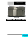
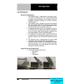
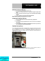
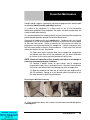
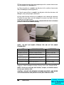
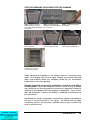
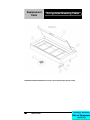
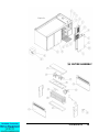
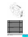
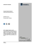
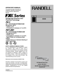
OPERATOR’S MANUAL
This manual provides information on
installation, operating, maintenance,
trouble shooting & replacement parts for
CHICK-FIL-A
REFRIGERATED
BREADING TABLE
52365WPRM-CFA
NOTIFY CARIER OF DAMAGE AT ONCE.
It is the responsibility of the consignee to inspect the
container upon receipt of same and to determine the
possibility of any damage, including concealed
damage. Randell suggests that if you are suspicious
of damage to make a notation on the delivery receipt.
It will be the responsibility of the consignee to file a
claim with the carrier. We recommend that you do so
at once.
525 South Coldwater Road • Weidman, MI 48893
888-994-7636 • Fax 888-864-7636 • unifiedbrands.net
7/24/2009
PP MNL0502 rev C
Table of Contents
page 2………………………………….…………Congratulations
page 3……………………………………Parts & Service Hotline
page 3………………………………...…Serial Number Location
page 4-7……………………………….Randell Limited Warranty
page 8…………………………………………Unit Specifications
page 9……………………………………….........Unit Installation
page 10-12....……………………………………...Unit Operation
page 13-15……………………………..Preventive Maintenance
page 16………………………………………..Electrical Diagram
page 17……………………………………..……Troubleshooting
page 18-20…………………………….……..Replacement Parts
Congratulations on your recent purchase of Randell food service equipment,
and welcome to the growing family of satisfied Randell customers.
Our reputation for superior products is the result of consistent quality
craftsmanship. From the earliest stages of product design to successive steps
in fabrication and assembly, rigid standards of excellence are maintained by
out staff of designers, engineers, and skilled employees.
Only the finest heavy-duty materials and parts are used in the production of
Randell brand equipment.
This means that each unit, given proper
maintenance will provide years of trouble free service to its owner.
2
800-621-8560
In addition, all Randell food service equipment is backed by
some of the best warranties in the food service industry and by
our professional staff of service technicians.
Retain this manual for future reference.
NOTICE: Due to a continuous program of product improvement, Randell
reserves the right to make changes in design and specifications without prior
notice.
NOTICE: Please read the entire manual carefully before installation. If certain
recommended procedures are not followed, warranty claims will be denied.
MODEL NUMBER _________________________
SERIAL NUMBER _________________________
INSTALLATION DATE _____________________
The serial number is located inside the right door on the interior rear
wall of the refrigerated base compartment.
800-621-8560
Randell Service and Parts
Hotline
unifiedbrands.net
3
Unit Specifications
52365WPRM-CFA
Model
52365WPRM-CFA
8
L
D
H
Work
Hgt.
Doors
H.P.
Volts
Amps
NEMA
Cubic
Volume
Ship
Wt.
65"
33"
41.25"
38.5"
3
1/2
115
10
5-15P
52.135
492
800-621-8560
Unit Installation
SELECTING A LOCATION FOR YOUR NEW UNIT
The following conditions should be considered when selecting a location for your
unit:
1. Floor Load: The area on which the unit will rest must be level, free of
vibration, and suitably strong enough to support the combined weights
of the unit plus the maximum product load weight. All casters must be
in contact with the floor to support the weight. Casters may require
shims in order for the caster to be in contact with the floor.
NOTE: If there is a question pertaining to weight load limits, consult the
factory at 1-800-621-8560.
2. Ventilation: The air cooled self contained unit requires a sufficient
amount of cool clean air. Also, avoid locating in an unheated room or
where the room temperature may drop below 55° F (13°C) or about
86°F (32°C).
INSTALLATION CHECKLIST
After the final location has been determined, refer to the following checklist prior to
start-up:
1. Check all visible components for any potential damage
2. Check that the condenser and evaporator fans rotate freely without
striking any stationary members.
3. Power up unit once plugged in.
4. Allow unit time to cool down to holding temperature.
5. Refer to the front of this manual for serial number location. Please
record this information in your manual on page 3 now. It will be
necessary when ordering replacement parts or requesting warranty
service.
6. Confirm that the unit is holding temperature.
7. Allow your unit to operate for approximately 45 minutes before putting
in food to allow interior of unit to cool down to storage temperature.
NOTE: All motors are oiled and sealed.
NOTE:
FAILURE TO FOLLOW INSTALLATION GUIDELINES AND
RECOMMENDATIONS MAY VOID THE WARRANTY ON YOUR UNIT.
ELECTRICAL SUPPLY: The wiring should be done by a qualified electrician in
accordance with local electrical codes. A properly wired and grounded outlet will
assure proper operation. Please consult the data tag attached to the compressor
to ascertain the correct electrical requirements. Supply voltage and amperage
requirements are located on the serial number tag located on the rear interior wall. .
NOTE: It is important that a voltage reading be made at the compressor
motor electrical connections, while the unit is in operation to verify the
correct voltage required by the compressor is being supplied. Low or high
voltage can detrimentally affect operation and thereby void its warranty.
unifiedbrands.net
9
Unit Operation
UNIT INFORMATION
Mechanical Compartment
1. The breading station is supplied with a main power switch.
The switch is located on the rear of electrical box behind
the upper hinged vented door. The main power switch will
completely shut down the upper rail as well as the lower
refrigerated base.
2. The rail power switch is located on the front of the electrical
box. The rail power switch will shut down the rail for nightly
shut down and cleaning. The lower refrigerated base will
continue to cool when the rail power switch is off.
3. Two digital temperature controls are located on the front of
the electrical box. The upper control regulates temperature
for the rail and the lower control regulates temperature for
the refrigerated base. (See Unit Operation page 11).
4. The condenser filter indicator light is located on the front of
the electrical box. If illuminated the condenser filter must be
cleaned or replaced. (See Preventative Maintenance page
12).
5. The condenser filter is located behind the lower hinged
vented door. (See Preventative Maintenance page 12).
6. The drain valve for the upper rail is found behind the upper
hinged vented door. The rail may be drained by placing a
pan under the drain valve and opening the valve. (See
Evening Shut Down of Prep Rail).
Upper Rail Lid and Lift Mechanism
1. The lid can be positioned three ways
• Fully closed
• Opened
• Fully opened
Note: All cleaning of rail lift mechanism must be done while lid is in closed position. The tension of the
lift mechanism has been pre-set at the factory.
10
800-621-8560
Unit Operation - cont.
MORNING STARTUP OF PREP RAIL
1. Unit cleaning may be performed at this time.
2. Turn on unit. Power switch for rail is found behind upper hinged vented
door.
3. Allow a minimum 45 minutes for your unit to cool down before loading
product.
4. Load the product and proceed with food preparation.
Note: Product entering unit must be at 41°F or less.
EVENING SHUT DOWN OF PREP RAIL
1. Remove product from unit at the end of the day’s preparation.
2. Turn off unit
3. Unit cleaning may be performed at this time if the frost has melted off
the surface.
4. Once defrosted, the rail drain may be opened to remove any water that
has resulted from the defrosting procedure.
TEMPERATURE CONTROLS
Your refrigerated breading table is equipped with a temperature adjustment control
for the refrigerated rail as well as a temperature adjustment control for the
refrigerated base which are located inside the mechanical housing behind the
upper hinged vented door.
Figure 1 illustrates the outer panel of the mechanical housing. The upper temperature control is for
the refrigerated rail and the lower temperature control is for the refrigerated base.
unifiedbrands.net
11
Unit Operation - cont.
To raise temperature in the refrigerated rail:
A. Push and hold the “set” button until 34 appears then release the “set”
button. 34 is the current set point temperature.
B. Push and release the up arrow 2 times until 36 is displayed. Push and
release the “set” button one time. The new set point, 36, will flash 3
times and then will be locked in.
To lower temperature in the refrigerated rail:
A. Push and hold the “set” button until 34 appears and then release the
“set” button. 34 is the current set point temperature.
B. Push and release the up arrow 2 times until 32 is displayed. Push and
release the “set” button one time. The new set point, 32, will flash 3
times and then will be locked in.
NOTE: It is recommended to only make changes of 2 degree increments
at a time. Allow for the unit to operate 24 hours between adjustments. If
the 2 degree adjustment is not enough another adjustment can be made.
The maximum highest setting is 38 degrees and the minimum lowest
setting is 28 degrees. If the settings need to go above or below this point
there may be other contributing factors as to the cause of the
temperature variances, please contact the factory at 1-800-621-8560.
To raise the temperature in the refrigerated base:
A. Push and hold the “set” button until 34 appears then release the “set”
button. 34 is the current set point temperature.
B. Push and release the up arrow 2 times until 36 is displayed. Push and
release the “set” button one time. The new set point, 36, will flash 3
times and then will be locked in.
To lower temperature in the refrigerated base:
A. Push and hold the “set” button until 34 appears and then release the
“set” button. 34 is the current set point temperature.
B. Push and release the up arrow 2 times until 32 is displayed. Push and
release the “set” button one time. The new set point, 32, will flash 3
times and then will be locked in.
NOTE: It is recommended to only make changes of 2 degree increments at a
time. Allow for the unit to operate 24 hours between adjustments. If the 2
degree adjustment is not enough another adjustment can be made. The
maximum highest setting is 38 degrees and the minimum lowest setting is
28 degrees. If the settings need to go above or below this point there may be
other contributing factors as to the cause of the temperature variances,
please contact the factory at 1-800-621-8560.
12
800-621-8560
Preventive Maintenance
Randell strongly suggests a preventive maintenance program which would include
the following monthly, weekly, and daily procedures:
If a failure of the equipment is a direct result of any of the Preventative
Maintenance guidelines being neglected, the repairs and parts replacements will
not be covered under warranty.
It is recommended that the customer contact the local Authorized Service Agent to
provide a quote to perform periodic Preventative Maintenance.
Cleaning of all condenser coils on a monthly basis. Condenser coils are a critical
component in the life of the compressor and must remain clean to assure proper
air flow and heat transfer. Failure to maintain this heat transfer will affect unit
performance and eventually destroy the compressor. Clean the condenser coils
with coil cleaner and/or a vacuum, cleaner and brush. Proper care of the filter will
reduce the need for this task. See item #6.
1A. Open lower louver ventilation door for the compressor compartment
and remove mesh filter to view the condenser coil. Use brush attachment
for vacuum in this area to vacuum all particles out of this area.
NOTE: Brush coil in direction of fins, normally vertically as to not damage or
restrict air from passing through condenser.
1B. Remove 4 phillips screws on right exterior side of compressor
compartment to gain access to condensing unit. Vacuum all loose particles
that can be seen being careful not to damage any wires or copper lines.
1C. Blow out condenser coil from rear to front of unit with compressed air
(30 PSI maximum). Forcing air in this direction allows the particles to exit
the same direction in which they had entered.
Accessing the Mechanical Housing
Step 1: Remove 4 screws.
Step 2: Pull off side panel.
Step 3: Access components.
2. Clean and disinfect drains with a solution of warm water and mild detergent on
a monthly basis.
unifiedbrands.net
13
3. Clean and disinfect drain lines and evaporator pan with a solution of warm water
and mild detergent on a monthly basis.
4. Clean all gaskets on a weekly if not daily basis with a solution of warm water
and a mild detergent to extend gasket life.
5. Clean the grease filter on a weekly if not daily basis with either hot water, mild
detergent, or by cycling through a dishwasher.
6. Clean upper lid hinge mechanism on a daily basis with a damp cloth containing
a solution of warm water and mild detergent to remove any debris that may
interfere with the hinge function.
Note: The upper lift mechanism must be cleaned while the lid is in the down
position. Do not lift the lid while cleaning.
Wipe along roller guide as well as the surface the roller rolls along
NOTE: DO NOT USE SHARP UTENSILS FOR ANY OF THE ABOVE
PROCEDURES.
JOB
CLEANING AGENT
COMMENTS
Routine cleaning
Soap, ammonia, detergent Medallion
Apply with a sponge or cloth
Fingerprints and smears
Arcal 20, Lac-O-Nu, Ecoshine
Provides a barrier film
Stubborn stains and
discoloration
Cameo, Talc, Zud, First Impression
Rub in the direction of the
polish lines
Greasy and fatty acids,
blood, burnt-on foods
Easy-Off, Degrease It, Oven Aid
Excellent removal on all
finishes
Grease and Oil
Any good commercial detergent
Apply with a sponge or cloth
Restoration/Preservation
Benefit, Super Sheen
Good idea monthly
Reference: Nickel Development Institute, Diversey Lever, Savin, Ecolab, NAFEM.
NOTE: Do not use steel pads, wire brushes, scrapers, or chloride cleaners
to clean your stainless steel.
CAUTION: DO NOT USE ABRASIVE CLEANING SOLVENTS, AND NEVER
USE HYDROCHLORIC ACID (MURIATIC ACID) ON STAINLESS STEEL.
14
800-621-8560
STEPS FOR REMOVING THE GREASE FILTER FOR CLEANING
Step 1: Locate grease filter
on the front of the condenser
air in duct. Behind lower hinged
vented door.
Step 2: Locate finger hole
opening to remove filter without
the use of tools.
Step 3: Insert finger and force
filter upwards.
Step 4: Filter should fall
out in your hands.
Step 5: Pull downwards to
release the filter at the top.
Step 6: Filter should fall
out of the top holding bracket.
Step 7: Removing the filter also
also allows access to the
condenser for cleaning.
Proper maintenance of equipment is the ultimate necessity in preventing costly
repairs. By evaluating each unit on a regular schedule, you can often catch and
repair minor problems before they completely disable the unit and become
burdensome on your entire operation.
For more information on preventive maintenance, consult the local ASA or
CFESA member. Most repair companies offer this service at very reasonable
rates to allow you the time you need to run your business along with the peace of
mind that all your equipment will last throughout its expected life. These services
often offer guarantees as well as the flexibility in scheduling or maintenance for
your convenience.
Randell believes strongly in the products it manufactures and backs those products
with one of the best warranties in the industry. We believe with the proper
maintenance and use, you will realize a profitable return on your investment and
years of satisfied service.
unifiedbrands.net
15
Electrical Diagram
16
800-621-8560
Trouble Shooting Guide
SYMPTOM
POSSIBLE CAUSE
Unit doesn't run
1.
2.
3.
4.
5.
6.
7.
8.
Unit short cycles
1. Condenser coil/filter dirty
2. Condenser fan faulty
3. Compressor faulty
4. Overload repeatedly tripping
5. Solenoid not seating
1. Clean coil/filter
2. Service fan and motor.
3. Call ASA for service
4. Check outlet voltage
5. Call ASA for service
Unit runs constantly
1. Condenser coil/filter dirty
2. Condenser fan faulty
1. Clean coil/filter
2. Service condenser motor
3. Filter light on
1. Temperature control set too
high
2. Temperature control faulty
3. Clean/change condenser filter
Unit not cold enough
No power to unit
Temperature control turned off
Temperature control faulty
Compressor overheated
Condenser fan faulty
Overload protector faulty
Compressor relay faulty
Compressor faulty
PROCEDURE
1.
2.
3.
4.
5.
6.
7.
8.
Plug in unit
Check temperature control
Test temperature control
Clean condenser coil/filter
Service condenser fan
Test overload
Test relay
Call ASA for service
1. Adjust control to lower setting
2. Test control
3. Condenser coil/filter dirty
4. Filter light on
5. Refrigerant leaking or
contaminated
3. Clean coil/filter
4. Clean/change condenser filter
Unit too cold
1. Temperature control set too low
2. Temperature control faulty
1. Adjust control to raise setting
2. Test control
Dixell control errors
1. Flashing “HA”
2. Flashing “P1”
1. High Alarm error
2. Primary probe failure
3. Flashing “P2”
3. Secondary (defrost) probe failure
1. Compressor mountings loose or
hardened.
1. Tighten or replace compressor
mountings
2. Condenser fan damaged or
hitting fan shroud
2. Inspect condenser fan
Unit noisy
5. Call ASA for service
unifiedbrands.net
17
Replacement
Parts
Refrigerated Breading Tables
CAUTION: Hold lid with both hands securely at all times during opening and closing.
18
800-621-8560
unifiedbrands.net
19
ITEM
DESCRIPTION
PART #
1
Hinged Cover with Recessed Handle
RP PCR0501
2
Counter Balance Hinge Lift Assy
HD HNG0501
3
Adapter Grid, 12” x 20”
RP ADP0801
4
Drain Screen, 2”
RP DSN002
5
Elbow, 1 ½” PVC Fem x Glue
PB ELB9905
6
Pipe, 1 ½” PVC
PB PIP150
7
Ball Valve, 1 ½” PVC Female
PB VLV9901
8
Dixell Digital Control for Base
RP CNT0204
9
Rocker On/Off Switch for Rail
EL SWT0502
10
Dixell Digital Control for Rail
RP CNT0501
11
Clean Condenser Indicator Light
EL LGT0305
12
Louver Knob, Aluminum
HD PIN0102
13
Louver Door – Top
RP LVR0707
13A
Louver Door – Bottom
RP LVR0708
14
Shelf Pins, Aluminum
HD PIN0102
15
Shelf, 13-1/8” x 25-1/4” Stainless Steel
HD SHL015SS
16
Door Hinge Top/Bottom
HD HNG0706
16A
Door Hinge Self Closure Spring (Bottom Only)
HD HNG0707
17
Toe Style Bracket/Door Handle, Stainless Steel
RP HDL0501
18
Door Gasket
IN GSK1020
19
Evaporator Fan Motor, 120V w/blade
EL MTR2338
20
800-621-8560
20
Temperature Control Probe - Dixell
RF CNT0505
21
Evaporator Condensate Pan, Plastic
RP DRP107
22
Expansion Valve
RF VLV404
23
Shield Panel for Base Coil Assembly
RP PNL107
24
Evaporator Coil Assembly
RP CSY108SL
24A
Evaporator Coil
RF COI107
25
Solenoid Valve
RF SOL9801
26
Evaporator Fan Shroud
RP SHD107
27
Mounting Support Bracket for Base Coil Assembly
RP SPT0500
28
Door Assembly with Toe Bracket, Right Hinge
RP DOR0708
29
Door Assembly with Toe Bracket, Left Hinge
RP DOR0707
30
Caster, 4-1/2” Overall with locking mechanism
HD CST030
30A
Caster, 4-1/2” Overall without locking mechanism
HD CST031
31
Condensing Unit Shroud
RP HSG0501
32
Magnetic Catch & Bracket Assembly for Louver Door
RP CTH0501
33
Magnetic Catch
HD CTH9901
34
Magnetic Catch Plate
RP BRK0508
35
Grease Filter, Condenser 9-1/2” x 11” Alum. w/pull handle
HD FLT0701
36
Condensing Unit
RF CON9901
37
Condenser Fan Blade
RF FAN007
38
Condenser Fan Motor
RF MTR0101P
39
Compressor
RF CMP9902P
40
40W shatterproof light bulb
EL LGT200
unifiedbrands.net
21