1
ISTA
User's Manual
Release 2.x
Technical Documentation
and Diagnosis
www.bmwicom.net
BMW Group
Page 2
Documentation/ISTA User's Manual
of
132
Contents
1
Introduction....................................................................................................................................5
1.1
Explanation of the symbols used ................................................................................................5
1.2
Important security instructions ....................................................................................................5
1.3
Chapter contents .........................................................................................................................6
1.4
Integrated Service Technical Application (ISTA) ........................................................................6
1.4.1
Integrated Service Information Server (ISIS) ...................................................................7
1.4.2
Integrated Service Information Display (ISID) ..................................................................7
1.4.3
Integrated Measurement Interface Box (IMIB) .................................................................7
1.4.4
Integrated Communication Optical Module (ICOM) .........................................................7
1.4.5
Integrated Service Access Point (ISAP) ...........................................................................7
1.4.6
Personal Computer (PC) ..................................................................................................8
1.4.7
Printer ...............................................................................................................................8
1.5
ISTA operating modes.................................................................................................................8
1.5.1
HO workshop mode ..........................................................................................................8
1.5.1.1
1.5.1.2
Online............................................................................................................................................. 8
Offline............................................................................................................................................. 8
1.5.2
TeleServices .....................................................................................................................8
1.6
Data exchange with other systems .............................................................................................9
1.6.1
ISPA Broker ......................................................................................................................9
1.6.2
JET stream .....................................................................................................................10
1.7
Distinguishing different makes ..................................................................................................10
1.8
General operation of the ISTA workshop system .....................................................................11
1.8.1
Symbol bar......................................................................................................................11
1.8.2
Header ............................................................................................................................12
1.8.3
Navigation area...............................................................................................................12
1.8.4
Content range .................................................................................................................12
1.8.5
Comment line..................................................................................................................12
1.8.6
Action line .......................................................................................................................12
1.8.7
Options for text entry (on-screen keyboard)...................................................................13
2
2.1
2.2
2.3
2.4
2.5
2.6
2.7
2.8
2.9
2.10
2.11
3
Overview and short introduction ...............................................................................................14
Starting the ISTA Client.............................................................................................................14
Checking the operations list ......................................................................................................15
Selecting a vehicle ....................................................................................................................16
Selecting a diagnostic connection to the vehicle ......................................................................17
Creating an operation................................................................................................................18
Finding out about operation details ...........................................................................................19
Perform vehicle test...................................................................................................................21
Display fault memory.................................................................................................................22
Editing a test plan......................................................................................................................23
Running a procedure.................................................................................................................24
Terminating an operation ..........................................................................................................25
Menu structure.............................................................................................................................26
3.1
Start mask .................................................................................................................................28
3.1.1
Displaying new items ......................................................................................................29
3.2
Identification ..............................................................................................................................30
V 1.0/2008-11-04
www.bmwicom.net
Copyright © BMW AG 2008
BMW Group
Page 3
Documentation/ISTA User's Manual
of
3.2.1
3.2.1.1
3.2.1.2
3.2.1.3
3.2.1.4
3.2.2
3.2.2.1
3.2.2.2
3.2.2.3
3.2.2.4
132
Vehicle selection.............................................................................................................30
Operations list .............................................................................................................................. 31
Vehicle identification number ....................................................................................................... 35
Reading out vehicle data.............................................................................................................. 36
Basic features .............................................................................................................................. 37
Operation information .....................................................................................................40
Operation details .......................................................................................................................... 40
Vehicle details .............................................................................................................................. 41
Repair history ............................................................................................................................... 43
Operations report ......................................................................................................................... 44
3.3
Vehicle test................................................................................................................................45
3.3.1
Control unit tree ..............................................................................................................46
3.3.1.1
Control unit functions ................................................................................................................... 47
3.3.2
Control unit list ................................................................................................................50
3.4
Activities ....................................................................................................................................51
3.4.1
Information search ..........................................................................................................51
3.4.1.1
3.4.1.2
3.4.1.3
3.4.1.4
3.4.2
3.4.2.1
3.4.2.2
3.4.3
3.4.3.1
3.4.4
3.4.4.1
3.4.4.2
3.4.4.3
3.4.5
3.4.5.1
3.4.5.2
3.4.5.3
Product structure.......................................................................................................................... 51
Function structure ........................................................................................................................ 54
Components and signals.............................................................................................................. 55
Text search .................................................................................................................................. 56
Assisted troubleshooting ................................................................................................58
Fault memory ............................................................................................................................... 58
Fault pattern................................................................................................................................. 60
Service function ..............................................................................................................62
Service functions.......................................................................................................................... 62
Workshop/Operating fluids .............................................................................................63
Workshop equipment ................................................................................................................... 63
Operating fluids ............................................................................................................................ 64
Text search .................................................................................................................................. 65
Measuring devices..........................................................................................................66
Multimeter .................................................................................................................................... 68
Oscilloscope................................................................................................................................. 71
Signals ......................................................................................................................................... 81
3.5
Service plan...............................................................................................................................83
3.5.1
Hit list ..............................................................................................................................83
3.5.2
Test plan .........................................................................................................................92
3.5.2.1
3.5.2.2
Displaying and editing a procedure .............................................................................................. 95
Displaying and editing a procedure in BST mode ........................................................................ 98
3.6
Symbol bar ................................................................................................................................99
3.6.1
Start mask.....................................................................................................................100
3.6.2
History list .....................................................................................................................100
3.6.3
Administration ...............................................................................................................101
3.6.3.1
3.6.3.2
3.6.3.3
3.6.4
3.6.5
3.6.6
3.6.7
3.6.8
3.6.8.1
3.6.8.2
3.6.8.3
Client settings ............................................................................................................................ 101
Dealer data ................................................................................................................................ 103
Software status .......................................................................................................................... 104
Connection manager ....................................................................................................105
Operating mode ............................................................................................................107
Status display ...............................................................................................................108
Printing..........................................................................................................................109
Help functions ...............................................................................................................110
Table of contents ....................................................................................................................... 111
List of abbreviations ................................................................................................................... 112
Units converter ........................................................................................................................... 113
V 1.0/2008-11-04
www.bmwicom.net
Copyright © BMW AG 2008
BMW Group
Page 4
Documentation/ISTA User's Manual
of
132
3.6.9
Minimize workshop system...........................................................................................114
3.6.10
Close operation/application ..........................................................................................114
3.7
Operations...............................................................................................................................115
3.7.1
Creating an operation ...................................................................................................115
3.7.1.1
3.7.1.2
3.7.1.3
3.7.1.4
3.7.1.5
3.7.1.6
3.7.2
Statuses ........................................................................................................................118
3.7.2.1
3.7.2.2
3.7.2.3
3.7.2.4
3.7.3
3.7.4
3.7.5
3.7.6
3.7.7
3.7.8
4
4.1
4.2
4.3
4.4
4.5
Identification via operations list .................................................................................................. 115
Identification via VIN entry ......................................................................................................... 116
Vehicle identification by reading out vehicle data....................................................................... 116
Vehicle identification by reading out vehicle data....................................................................... 116
Vehicle identification via Basic features ..................................................................................... 117
Identification in "TeleServices" operating mode ........................................................................ 118
New............................................................................................................................................ 119
In progress ................................................................................................................................. 119
Interrupted.................................................................................................................................. 120
Terminated................................................................................................................................. 120
Simultaneous access to an ISTA operation .................................................................121
Time-dependent status change ....................................................................................121
Workshop PC................................................................................................................121
ISID in offline mode ......................................................................................................121
TeleServices .................................................................................................................121
Terminating an operation..............................................................................................122
Appendix ....................................................................................................................................123
Scope of functions for operator devices..................................................................................123
Abbreviations...........................................................................................................................125
Glossary ..................................................................................................................................126
Fault messages and fault rectification.....................................................................................127
Index........................................................................................................................................129
V 1.0/2008-11-04
www.bmwicom.net
Copyright © BMW AG 2008
BMW Group
Page 5
Documentation/ISTA User's Manual
of
132
1 Introduction
1.1 Explanation of the symbols used
In this user's manual, the following symbols have the following meanings:
WARNING
The "WARNING" symbol indicates actions that could result in personal injuries.
CAUTION
The "CAUTION" symbol refers to actions that could result in material damage.
NOTE
The "NOTE" symbol indicates text passages that are especially important, e.g. in
relation to procedures, so that undesired or unexpected results are not produced.
Information
The "INFORMATION" symbol refers to other documentation.
1.2 Important security instructions
Before using ISTA software, you should familiarize yourself with the relevant security regulations
and comply with the instructions in this manual.
WARNING
Certain functions in ISTA may result in the activation of components in the connected
vehicle. Before components are activated, make sure that no one is in the danger area.
The general safety regulations should be observed.
V 1.0/2008-11-04
www.bmwicom.net
Copyright © BMW AG 2008
BMW Group
Page 6
Documentation/ISTA User's Manual
of
132
1.3 Chapter contents
This document is organized as follows:
Chapter 1 contains general information on the workshop system and on the correct use of the
user's manual.
Chapter 2 guides you step-by-step from the start mask to the test plan and helps you to get started.
Chapter 3 provides a detailed description of all functions of the workshop system.
Chapter 4 contains a list of abbreviations and a glossary as well as a fault list.
The operation, display screens and functions of the installed ISTA client are all described in this
manual. The user's manual is primarily intended for service technicians working in the workshop
environment.
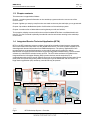
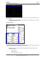
1.4 Integrated Service Technical Application (ISTA)
ISTA or the ISTA workshop system consists of several functionally oriented system components
that communicate with each other via LAN, WLAN and Internet. The entire system supplies up-todate diagnostic data and information from BMW headquarters. The primary applications of the
terminal devices are powerful diagnostics on the vehicle, with various options for vehicle
identification for highly specific information searches and guided troubleshooting. The associated
software is a client/server solution known as ISTA. The ISTA client software is installed on the
Integrated Service Information Display (ISID) operator devices and the workshop PC. It
communicates with the ISTA server software that runs on the Integrated Service Information Server
(ISIS). ISID can operate temporarily offline and then be resynchronized later with the server. In a
large dealer organization (HO) workshop, several ISIS may be present.
ISIS
Printer/Workshop PC
BMW AG
ISAP
ISID with docking station
Workshop PC
ICOM
Fig.11
ISID
IMIB
ISTA Workshop System – Overview
V 1.0/2008-11-04
www.bmwicom.net
Copyright © BMW AG 2008
BMW Group
Page 7
Documentation/ISTA User's Manual
of
1.4.1
132
Integrated Service Information Server (ISIS)
ISIS is the workshop server. In addition to other applications, the server-specific component of the
ISTA software is installed on ISIS.
The workshop server is connected with BMW AG via an internet link. BMW AG makes the data
available via the ISPA Broker (Chapter 1.6.1) and JET stream (Chapter 1.6.2).
1.4.2
Integrated Service Information Display (ISID)
ISID is a mobile tester for workshop use integrated into the workshop network. The scope of
delivery consists of a control panel, a base station and accessories. An ISTA client is installed on
the ISID. The device can be operated "online" (in conjunction with the ISTA server) or "offline"
(temporary interruption of connection with the ISTA server). For additional information, see Chapter
1.5.
1.4.3
Integrated Measurement Interface Box (IMIB)
The IMIB is a powerful measuring instrument that is used in the BMW Group dealer organization. It
contains several measuring units that can simulate the performance of an oscilloscope or a digital
multimeter. The IMIB contains adjustable current and voltage sources which can be used as voltage
and current supplies.
You can use the IMIB as a multimeter, even if not connected to ISTA, or execute more complex
functions with ISTA. You can establish a link between ISID and IMIB via LAN or WLAN. The IMIB
can be operated in two modes in conjunction with ISTA:
• interactively as a manually adjusted measuring instrument
• embedded in test processes as an automated measuring instrument
With the manually adjusted measuring instrument you can make manual settings in the relevant
masks once a connection to the measuring instrument system has been established. The results
are displayed in the mask. For additional information, see Chapter 3.4.5.
With the guided measuring instrument, the measuring instrument system is automatically adjusted
via program instructions in the test sequence. The results are displayed in specific masks and
evaluated by the program.
1.4.4
Integrated Communication Optical Module (ICOM)
ICOM is a communication device and constitutes the diagnostic interface to the vehicle. It is
connected to the vehicle and can be linked to an ISID via a connection manager. Thus ISID can
communicate with the vehicle, e.g. for automatic vehicle identification, or for executing test
programs.
1.4.5
Integrated Service Access Point (ISAP)
ISAP is a communication device (Access Point) for linking WLAN-capable devices to the workshop
network.
V 1.0/2008-11-04
www.bmwicom.net
Copyright © BMW AG 2008
BMW Group
Page 8
Documentation/ISTA User's Manual
of
1.4.6
132
Personal Computer (PC)
You can also install an ISTA client on a PC or a workshop PC, for example. As these devices are
fixed, a PC is primarily suitable for information searches.
1.4.7
Printer
Approved and standard commercial network printers are used for printing jobs.
1.5 ISTA operating modes
1.5.1
HO workshop mode
In the HO workshop mode, the terminal devices can be operated both "online" (default) as well as
"offline".
1.5.1.1 Online
In this operating mode, the client and the workshop server are located in an HO workshop and are
connected via the local workshop network (LAN, WLAN). An online connection to BMW AG is
established. ISTA software can be operated on a mobile ISID and/or a stationary workshop PC.
The online link not only supports the prompt update of ISTA data and software, but also provides
access to data from other systems at BMW headquarters. Data access usually occurs in the
background when certain functions are accessed.
1.5.1.2 Offline
In this mode, the client is temporarily separated from the workshop server. For example, this is
necessary if the ISID is used on a test drive with the vehicle. The changeover from online to offline
mode and back again is performed by the Workshop Management System (WSM). Once the client
is online again, the software synchronizes itself automatically with the workshop server. The same
thing happens if the server crashes and is available again at a later point in time.
1.5.2
TeleServices
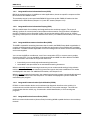
In the "TeleServices" operating mode, communication with the vehicle is performed via the mobile
phone network (GSM). The vehicle transmits a service call to the central TeleServices switchboard
(TSSB) either automatically triggered by Condition Based Service (CBS) scopes or manually by the
driver. In the process additional fault memory data and control device information is transmitted in
the form of a file. This data is transmitted to the home dealer of the customer via the TSSB and can
be read out there with ISTA.
This option is only available if the application for ISPA service advice and order control has been
installed on ISPA. ISTA is then called up in the "TeleServices“ operating mode by the service
advisor from the ISPA Client. The first mask that is displayed in ISTA after it is called up in this
mode is the fault memory list of the identified vehicle.
Only limited ISTA functions are available in the "TeleServices" operating mode. No direct link is
established with the vehicle at any time.
V 1.0/2008-11-04
www.bmwicom.net
Copyright © BMW AG 2008
BMW Group
Page 9
Documentation/ISTA User's Manual
of
132
Workshop PC
BMW headquarters
Fig. 12
TeleServices components
Fig. 1.3
TeleServices on workshop PC (no current screenshot)
HO workshop
After the data has been read out, the "Fault memory" mask is displayed. From here a test plan can
be accessed. You can now search for information objects.
1.6 Data exchange with other systems
1.6.1
ISPA Broker
Score Broker is an online interface with BMW AG. It enables the calling-up of information on
technical actions, fault patterns (Customer's own words/Customer's quote, qualified), vehicle
V 1.0/2008-11-04
www.bmwicom.net
Copyright © BMW AG 2008
BMW Group
Page 10
Documentation/ISTA User's Manual
of
132
details, repair history and vehicle rundown. The information is integrated into the respective masks
and requires an online connection of the ISPA Broker to BMW AG.
1.6.2
JET stream
JET stream is an online interface to BMW AG. It provides updated software (content and system
packages) and transmits nonprocedurally defined data to the vehicle description module (FBM) at
BMW AG. The information is integrated into the respective masks and requires an online link to
BMW AG.
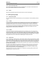
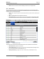
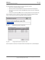
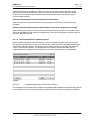
1.7 Distinguishing different makes
The user interface is standardized for the BMW, MINI and Rolls-Royce brands. The various brands depending on the authorization of the respective business - can be identified by the different colors
of the active objects in the display. A marked object is thus highlighted on the screen in the
respective brand color. Furthermore, depending on authorization level, the brand in the header of
the start mask will be displayed as text.
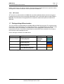
Colors and logos are listed in the table below.
Brand
Logo left
BMW Service
BMW Group
Multi-brand dealers Workshop System
Logo right
Color
MINI Service
Workshop
System
turquois
e
BMW
BMW Service
Workshop System
blue
MINI
MINI Service
Workshop System
orange
Rolls-Royce
Rolls-Royce Motorcars
Service Workshop System
chamois
Table 1-1
Logos and colors
V 1.0/2008-11-04
www.bmwicom.net
Copyright © BMW AG 2008
BMW Group
Page 11
Documentation/ISTA User's Manual
of
132
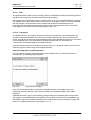
1.8 General operation of the ISTA workshop system
The graphic displays on the screen are known as "masks". These contain information and control
functions that enable the user to operate the ISTA workshop system.
The masks normally have a standard structure. They are divided into the following sections:
1. Symbol bar
2. Header
3. Navigation area
4. Content range
5. Comment line
6. Action line
1
2
3
4
5
6
Fig .1.4
1.8.1
Control and display areas
Symbol bar
The symbol bar is visible in all masks. The functions that can be called via the individual symbols are
described in Chapter 3.5.2.1.
V 1.0/2008-11-04
www.bmwicom.net
Copyright © BMW AG 2008
BMW Group
Page 12
Documentation/ISTA User's Manual
1.8.2
of
132
Header
The vehicle identification number and the basic features of the identified vehicle are displayed in
the header. The vehicle identification number is only displayed if the vehicle has been identified by
entering or reading out its vehicle identification number.
1.8.3
Navigation area
You can navigate among the individual functions of the workshop system using the:
◊
main menu (first line)
◊
submenu (second line), and
◊
tabs.
The selected menu items or tabs are marked in the appropriate brand color.
1.8.4
Content range
This is where you will find further selection options and information. A white arrow pointing up or
down identifies the column that is used for sorting a selection list.
1.8.5
Comment line
The bottom part of the content range may also contain a comment line in which you will receive
additional information.
1.8.6
Action line
Various buttons are shown here according to the content range.
V 1.0/2008-11-04
www.bmwicom.net
Copyright © BMW AG 2008
BMW Group
Page 13
Documentation/ISTA User's Manual
1.8.7
of
132
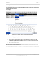
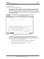
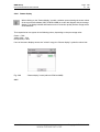
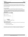
Options for text entry (on-screen keyboard)
In various masks, it may be necessary to enter text or characters. In general, this can be done using
the PC keyboard. By clicking on the "Keyboard" button you can fade in the so-called "on-screen
keyboard". Only keys that are necessary to make valid entries at the respective function step are
enabled on the on-screen keyboard. Impermissible characters cannot be selected with the onscreen keyboard.
A second click on the "Keyboard" button hides the on-screen keyboard.
Fig. 1.5
On-screen keyboard: Entering search terms
V 1.0/2008-11-04
www.bmwicom.net
Copyright © BMW AG 2008
BMW Group
Page 14
Documentation/ISTA User's Manual
of
132
2 Overview and short introduction
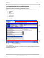
2.1 Starting the ISTA Client
► How to start the ISTA Client
◊
Double-click the symbol on the Windows desktop (if displayed)
◊
or
◊
Open the application in the program file by selecting
"Start – All Programs – ISTA – ISTA Client"; or
◊
or
◊
Open the application by selecting the corresponding entry on the central start
page on the ISID.
; or
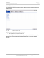
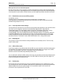
After selection, the start mask appears (Chapter 3.1). A list of news will be displayed.
You can set the display period in Administration.
Fig. 2.1
Start mask
If the date has changed since the last time the system was activated, the "ISTA usage notes"
will be displayed. After reading the note, close the popup window by clicking the "Continue" button.
You can initiate an identification procedure from the start mask.
► To initiate an identification procedure for a vehicle:
◊
Select the "Identification" menu.
V 1.0/2008-11-04
www.bmwicom.net
Copyright © BMW AG 2008
BMW Group
Page 15
Documentation/ISTA User's Manual
of
132
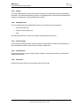
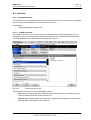
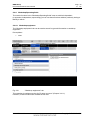
2.2 Checking the operations list
NOTE
In the "Central/online" operating mode (OSS and TeleServices), the "Operations list"
tab is not available for technical reasons. Proceed with Chapter 2.3.
After you have selected the "Identification" menu from the start mask, the workshop system
switches to the "Operations list" tab.
Each identification session generates a "procedure" that is automatically initiated and administered
by the workshop system for vehicle identification. At the end of the session an operation is closed
via a popup. The user can thus choose whether he wants to terminate or interrupt the operation.
Depending on the option selected, an operation is concluded via a popup, assigned a status
("terminated", "interrupted") and entered into the operations list for a certain period. Saved
procedures can be reopened from the operations list.
Additional information is available in Chapter 3.2.1.1.
Fig. 2.2
Operations list
The selection of an existing procedure is not suitable for the "Short introduction" provided here.
Therefore change to the "Read out vehicle data" tab.
V 1.0/2008-11-04
www.bmwicom.net
Copyright © BMW AG 2008
BMW Group
Page 16
Documentation/ISTA User's Manual
of
132
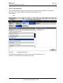
2.3 Selecting a vehicle
There are four options for initiating vehicle identification (Chapter 3.2):
◊
by selecting an operation
◊
by entering a vehicle identification number
◊
by reading out the vehicle data, or
◊
by selecting basic features.
The most reliable way to identify a vehicle is by reading out the vehicle data from a connected
vehicle.
► How to identify a vehicle by reading out the vehicle data and automatically creating an operation
to do this:
◊
Click the "Identification" main menu item in the navigation area.
◊
Select the "Read out vehicle data" tab and follow the instructions provided.
◊
Click the "OK" button.
Fig. 2.3
Preparations for reading out vehicle data
After a short interval, the connection manager appears.
V 1.0/2008-11-04
www.bmwicom.net
Copyright © BMW AG 2008
BMW Group
Page 17
Documentation/ISTA User's Manual
of
132
2.4 Selecting a diagnostic connection to the vehicle
The ISTA communication devices from the HO workshop are entered into the content range of the
connection manager.
► How to select the communication device:
◊
Determine which ICOM is connected to the vehicle to be identified.
◊
Select the appropriate components in the connection manager and click the "Set up
connection" button.
Fig. 2.4
Connection manager
V 1.0/2008-11-04
www.bmwicom.net
Copyright © BMW AG 2008
BMW Group
Page 18
Documentation/ISTA User's Manual
of
132
After the "Set up connection" button is selected and clicked, the connection will be set up. The
tester performs a vehicle identification. To do this, it reads out the vehicle identification number
from the vehicle. The progress of the identification procedure is displayed on a progress bar.
Fig. 2.5
Identification procedure
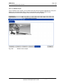
2.5 Creating an operation
After the identification procedure, the workshop system tries to uniquely assign the operation to an
existing operation. If this does not succeed, it automatically creates a new operation and switches
over directly to the "Operation details" mask (Chapter 2.6).
If operations with the same identification features are already available in the workshop system,
these will be offered for selection in the "Assignment/generation of operation" list.
V 1.0/2008-11-04
www.bmwicom.net
Copyright © BMW AG 2008
BMW Group
Page 19
Documentation/ISTA User's Manual
Fig. 2.6
of
132
Creating a new operation or selecting an existing operation
► How to assign an operation:
◊
Select an existing operation or click the "New operation" button.
◊
Click the "OK" button.
If no unique assignment is produced (e.g.: the other operation is open or several suitable operations
are available), a corresponding popup is displayed.
Additional information is available in Chapter 3.7.
2.6 Finding out about operation details
After automatic vehicle identification and manual operation assignment, you will obtain general
information on the vehicle in the "Operation details" mask (Chapter 3.2.2.1). In this mask you can
perform a vehicle test or look for information.
► How to start a vehicle test:
◊
Click the "Perform vehicle test" button.
V 1.0/2008-11-04
www.bmwicom.net
Copyright © BMW AG 2008
BMW Group
Page 20
Documentation/ISTA User's Manual
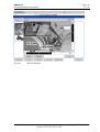
Fig. 2.7
of
132
Operation details (without an online connection to BMW AG)
Operation details for "Technical actions" and "Customer complaints" require an online connection
to BMW AG.
You can specifically search for various types of information via the "Search for information" button
(Chapter 3.4.1).
You can start the vehicle test by clicking on the "Perform vehicle test" button.
V 1.0/2008-11-04
www.bmwicom.net
Copyright © BMW AG 2008
BMW Group
Page 21
Documentation/ISTA User's Manual
of
132
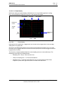
2.7 Perform vehicle test
The vehicle test runs automatically the first time for each operation. During the vehicle test, the
"Control unit tree" submenu (Chapter 3.3.1) is displayed by default. Alternatively you can switch to
the corresponding list of control devices by selecting the "Control unit list" entry from the submenu
(Chapter 3.3.2).
The control unit tree displays the maximum number of control units installed in a vehicle, and their
assignments in the respective bus system, in the form of a chart. At the beginning of the vehicle
test, the rectangular symbols are not colored. Non-installed control units in the identified vehicle
are shown in gray in the display. Currently processed (or selected) control units are displayed in the
color of the mask.
While the vehicle test is being performed, you can follow its progress on the screen as the displayed
symbols are updated in real-time.
From this mask, you can if required restart the vehicle test or also call up control unit functions so
that you can read out measurements or activate actuating elements.
Before you can access a test plan you must first display the fault memory.
► How to view the fault memory:
◊
Wait until the vehicle test is completed.
◊
Click the "Display fault memory" button.
Fig. 2.8
Control unit tree at the beginning of the vehicle test
V 1.0/2008-11-04
www.bmwicom.net
Copyright © BMW AG 2008
BMW Group
Page 22
Documentation/ISTA User's Manual
of
132
2.8 Display fault memory
After the vehicle test, go to the "Fault memory" mask (Chapter 3.4.2.1). The read-out
fault codes and the associated description will be listed. From this mask you can calculate
a test plan.
► How to calculate a test plan:
◊
Fig. 2.9
Click the "Test plan" button.
Display fault memory
You run the "Start quick delete" function when the guided troubleshooting is completed.
You can find details about this function in Chapter 3.4.2.1.
V 1.0/2008-11-04
www.bmwicom.net
Copyright © BMW AG 2008
BMW Group
Page 23
Documentation/ISTA User's Manual
of
132
2.9 Editing a test plan
The test plan (Chapter 3.5.2) lists the suspected components and functions.
The individual suspected components and functions are presented in white lettering against a dark
background. Underneath them the appropriate documents and procedures are listed in black
lettering against a light background (indicated in the "Type" column with "ABL").
Procedures localize a fault and provide advice on rectifying it.
► How to start a procedure:
◊
Select the required procedure from the test plan.
◊
Click the "Display" button.
Fig 2.10
Test plan
V 1.0/2008-11-04
www.bmwicom.net
Copyright © BMW AG 2008
BMW Group
Page 24
Documentation/ISTA User's Manual
of
132
2.10 Running a procedure
A procedure (service program) is primarily designed to identify the cause of a fault. Furthermore, service functions can be performed via procedures. Information can be displayed within
a procedure, as well as measurements read out or entered. Furthermore, queries can be made
available via selection screens.
After a procedure has been carried out, additional information will be added to the test plan,
if this turns out to be necessary for further fault search or fault rectification. In the test plan,
you can select and start another procedure.
The following mask gives an example of a question with the options "Yes" and "No".
Fig. 2.11
Example of procedure and "Question" (no current screenshot)
After the test plan has been completed, you should execute the "Quick delete" function
(Chapter 3.5.2).
V 1.0/2008-11-04
www.bmwicom.net
Copyright © BMW AG 2008
BMW Group
Page 25
Documentation/ISTA User's Manual
of
132
2.11 Terminating an operation
You can terminate an operation either by:
◊
Clicking the "X" symbol
◊
Identification of a new vehicle, or
◊
Calling up the start mask via the symbol with the same name.
In any case a dialogue will be displayed, showing options on how to terminate the operation
(Chapter 3.7.8).
Fig. 2.12
"Close operation" dialogue
► How to terminate the operation:
◊
Click on the "Start mask" symbol.
◊
For example, select the "Terminate operation" option.
The procedure will now be included in the operations list. You can if required reopen it
there (Chapter 3.2.1.1).
V 1.0/2008-11-04
www.bmwicom.net
Copyright © BMW AG 2008
BMW Group
Page 26
Documentation/ISTA User's Manual
of
132
3 Menu structure
This chapter describes the menus, masks, and buttons in detail. The sequence is largely based on
the menu structure. The functional sequence is created via cross-references to the chapters.
For a short overview and a rapid introduction to ISTA, you will find a brief description of the guided
diagnosis in Chapter 2.
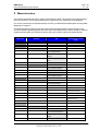
The following table provides an overview of the ISTA workshop system's menu structure. The
structure numbers appearing before the menu items correspond to the chapter numbers. Labels in
square brackets refers to the button functions that can be used to call up the masks directly.
Main menu
Submenu
Tab
Selection in the content
range
3.1 Start mask
3.2 Identification
3.2.1 Vehicle selection
3.2.1.1 Operations list
3.2.1.2 Vehicle identification
number
3.2.1.3 Reading out vehicle
data
3.2.1.4 Basic features
3.2.2 Operation information
3.2.2.1 Operation details
3.2.2.2 Vehicle details
3.2.2.3 Repair history
3.2.2.4 Operations report
3.3 Vehicle test
3.3.1 Control unit tree
Identification
Diagnostic query
Component activation
3.3.23.3.2 Control unit list
Identification
Diagnostic query
Component activation
3.4 Activities
3.4.1 Information search
3.4.1.1 Product structure
3.4.1.2 Function structure
3.4.1.3 Components and
signals
3.4.1.4 Text search
V 1.0/2008-11-04
www.bmwicom.net
Copyright © BMW AG 2008
BMW Group
Page 27
Documentation/ISTA User's Manual
Main menu
of
Submenu
Tab
132
Selection in the content
range
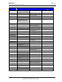
3.4.2 Guided troubleshooting
1)
3.4.2.1 Fault memory
3.4.2.2 Fault pattern
3.4.3 Service function
3.4.3.1 Service functions
3.4.4 Workshop/Operating
fluids
3.4.4.1 Workshop equipment
3.4.4.2 Operating fluids
3.4.4.3 Text search
3.4.5 Measuring instruments
3.4.5.1Multimeter
3.4.5.2 Oscilloscope
3.4.5.3 Signals
3.5 Service plan
3.5.1 Hit list
3.5.2 Test plan
3.6 Symbol bar
3.6.1 Start mask
3.6.2 History list
3.6.3 Administration
3.6.3.1 Client settings
3.6.3.2 Dealer data
3.6.3.3 Software status
3.6.4 Connection manager
3.6.5 Operating mode
3.6.6 Status display
3.6.7 Print
3.6.8 Help functions
3.6.8.1 Table of contents
3.6.8.2 List of abbreviations
3.6.8.3 Units converter
3.6.9 Minimize workshop
system
3.6.10 Close operation
1)
Not for E21 - E31 Series. Changeover to BST mode.
V 1.0/2008-11-04
www.bmwicom.net
Copyright © BMW AG 2008
BMW Group
Page 28
Documentation/ISTA User's Manual
of
132
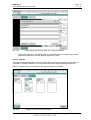
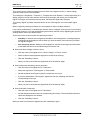
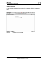
3.1 Start mask
When you access the ISTA workshop system, initially the start mask appears (Fig. 3.1). Once a day
a window appears when the system is booted up displaying the "ISTA usage notes".
Fig. 3.1
STA usage notes popup
After reading the note, close the popup window by clicking the "Continue" button.
Fig. 3.2
Start mask with news
In the start mask you can:
V 1.0/2008-11-04
www.bmwicom.net
Copyright © BMW AG 2008
BMW Group
Page 29
Documentation/ISTA User's Manual
of
◊
read new items (Chapter 3.1.1)
◊
access standard functions via the symbol bar (Chapter 3.5.2.1)
◊
access "Identification" main menu and initiate an operation (Chapter 3.2)
◊
access the main menu "Activities" and search for vehicle-specific information (Chapter
3.4.1).
132
When working on a vehicle and going through the main menu using the menu items "Identification",
"Vehicle test", "Activities" and "Service plan", you normally work from left to right.
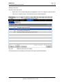
3.1.1
Displaying new items
The content range of the start mask contains a multicolumn listing of news from BMW
headquarters. The columns have the following meanings:
◊
News: shows the titles of all available news items.
◊
Date: shows the date on which the news item was last edited. When the start mask is
opened, the news items are sorted by date, with the most recent entry at the top. You can
delete older news items to make the list shorter (Chapter 3.6.3.1).
► How to change the sorting sequence:
◊
Click the column header with an arrow symbol in the start mask.
► How to change the order using another column:
◊
Click another column header. The arrow symbol jumps to the corresponding column.
The new order is retained until you quit the start mask.
► How to access a news item:
◊
Click a news item. The selection bar jumps to the corresponding line. The "Display" button
is activated.
◊
Click the "Display" button. The selected news item is displayed.
◊
Click the "Close" button, to return to the start mask (Fig. 3.2).
V 1.0/2008-11-04
www.bmwicom.net
Copyright © BMW AG 2008
BMW Group
Page 30
Documentation/ISTA User's Manual
of
132
3.2 Identification
A vehicle can be identified with any of four approaches. During identification, to assure unique
assignment of the diagnostic session, a new procedure will be created or an existing one used.
You can obtain detailed information on administering procedures in the Chapter 3.7 "Background
information on the procedure".
3.2.1
Vehicle selection
Before you can work with a particular vehicle, you must initiate an operation. The first step is to
select the vehicle
► How to start the vehicle selection:
◊
Fig. 3.3
◊
Click the "Identification" main menu item in the navigation area. If you do this from the start
mask and have previously created operations in the workshop, then the "Operation details"
tab is automatically selected. If you have selected the "Identification - vehicle selection"
menu from an open operation, the workshop system changes over to the "Operation
details" tab (Chapter 3.2.2.1) and displays the "Close operation" query.
"Close operation" dialogue
Decide whether the ongoing operation should be terminated or interrupted.
More information on this popup in Chapter 3.7.
V 1.0/2008-11-04
www.bmwicom.net
Copyright © BMW AG 2008
BMW Group
Page 31
Documentation/ISTA User's Manual
of
132
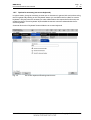
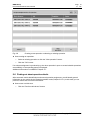
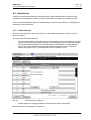
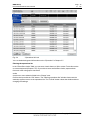
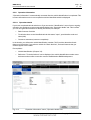
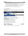
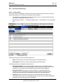
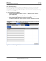
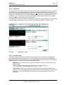
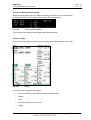
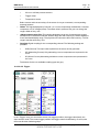
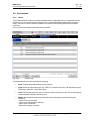
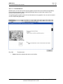
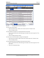
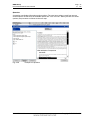
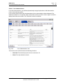
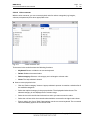
3.2.1.1 Operations list
In general, the vehicle identification /operation administration tries to uniquely assign an existing
procedure or independently generates a new one. If no unique assignment is produced (e.g.: the
other operation is open or several matching operations are available) the "Assignment/New" popup
or even the "Decision Operation/ VIN" popup is displayed.
NOTE
In the "Central/online" operating mode (TeleServices and OSS), the "Operations list"
tab is not provided because there is only ever one operation there.
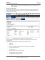
The operations list is automatically brought to the front when you select the "Identification" menu
from the start mask. The prerequisite is that procedures are already available in the "New“,
"Interrupted“ or "In progress" statuses. Terminated operations do not become visible until the
adjustable filter (Fig. 3.5) has been set accordingly
The operations list shows a table of all previously completed operations depending on the filter
settings and the time elapsed (Chapter 3.7.4). The table columns have the following meanings:
◊
Basic features: shows the basic features that are saved with the operation.
◊
Vehicle identification number: shows the vehicle identification number read out of the
vehicle. Reading out the vehicle identification number is part of the vehicle identification
procedure. It can also be automatically determined at a later stage with the identification via
Basic features with a vehicle test.
◊
Date/Time: shows the date and time at which the operation was first saved.
◊
Status: shows the status of the operation. A distinction is made among the following
statuses:
- New operations (new)
- Interrupted operations (interrupted)
- Ongoing operations (in progress)
- Terminated operations (terminated)
More information is available in Chapter 3.7.
The table is sorted by default according to the "Status" column.
V 1.0/2008-11-04
www.bmwicom.net
Copyright © BMW AG 2008
BMW Group
Page 32
Documentation/ISTA User's Manual
Fig. 3.4
of
132
"Operations list" tab
You can obtain background information on the "Operation" in Chapter 3.7.
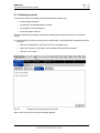
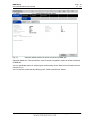
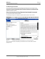
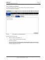
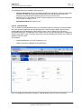
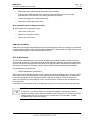
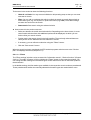
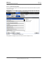
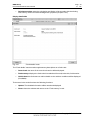
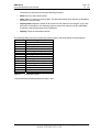
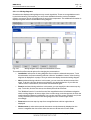
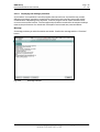
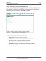
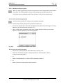
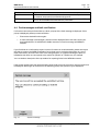
Filtering the operations list
In the "Enter filter criteria" field, you can enter a basic feature, a VIN or a date. To do this use the
on-screen keyboard (Chapter 1.8.7). If you wish to enter several filter criteria, separate them
from each other using space characters
and/or
check one or more selection fields in the "Status" area.
Confirm the input with the "OK" button. The "Filtering operations list" window closes and the
workshop system returns to the operations list. The "Cancel" button closes the window without
changing the settings.
V 1.0/2008-11-04
www.bmwicom.net
Copyright © BMW AG 2008
BMW Group
Page 33
Documentation/ISTA User's Manual
Fig. 3.5
of
132
"Filtering operations list" window
► How to display "terminated" operations in the operations list:
◊
Click the "Filter operations list" button. The "Filtering operations list" window opens.
◊
Mark the "Terminated" option and click "OK".
V 1.0/2008-11-04
www.bmwicom.net
Copyright © BMW AG 2008
BMW Group
Page 34
Documentation/ISTA User's Manual
of
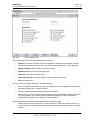
132
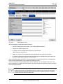
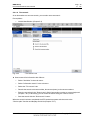
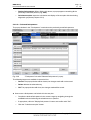
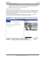
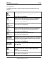
The following buttons are available in the action line:
◊
Set standard filter: This button resets the filter to the default settings: no filter criteria,
and only operations with "New", "In progress", and "Interrupted" status are displayed in the
corresponding sequence.
◊
Accept: Opens the selected operation.
If you have selected an operation that has been terminated, a dialogue appears in which
you can decide if this operation should be reopened or if a new operation should be created
and opened (Chapter 3.7.1).
Fig. 3.6
"Open/create operation" menu
V 1.0/2008-11-04
www.bmwicom.net
Copyright © BMW AG 2008
BMW Group
Page 35
Documentation/ISTA User's Manual
of
132
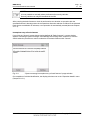
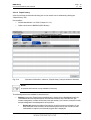
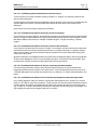
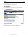
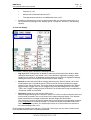
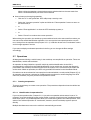
3.2.1.2 Vehicle identification number
If you select the "Identification" menu from the start mask, the "VIN" (Vehicle identification number)
tab will be automatically selected. Only the last seven characters are required when entering the
vehicle identification number. You can use the on-screen keyboard for making entries (Chapter
1.8.7).
Fig. 3.7
"Vehicle identification number (VIN)" tab
Confirm the input by clicking the "Accept" button.
After the vehicle identification number has been entered the ISTA workshop system checks
whether an operation with this number already exists. If a corresponding operation exists, you can
select it
and thus continue or create a new operation. If no suitable operation exists, a new operation will be
generated automatically. The associated basic features and other identification data will then be
read out of the server database. The workshop system changes over to the "Operation details"
mask (Chapter 3.2.2.1).
V 1.0/2008-11-04
www.bmwicom.net
Copyright © BMW AG 2008
BMW Group
Page 36
Documentation/ISTA User's Manual
of
132
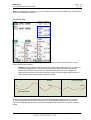
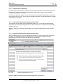
3.2.1.3 Reading out vehicle data
The VIN can be directly read out from the vehicle by using "Read out vehicle data".
First, the prerequisites are displayed.
Fig. 3.8
Prerequisites for vehicle identification
► How to read out vehicle data:
◊
Click the "Read out vehicle data" tab.
◊
Connect a vehicle interface (ICOM) to the vehicle.
◊
Switch on the ignition.
◊
Click the "OK" button. The request begins with checking the existing connection and
continues with the vehicle identification via the VIN readout. During this time, a progress
bar will be displayed on the mask.
V 1.0/2008-11-04
www.bmwicom.net
Copyright © BMW AG 2008
BMW Group
Page 37
Documentation/ISTA User's Manual
Fig. 3.9
of
132
Identification operation
After reading out the VIN the workshop system checks whether an operation with the same VIN is
already on the operations list. If this is the case, the operations list will be displayed to select an
existing operation. Otherwise a new operation will automatically be created (also see Chapter
3.7.1.2).
An exceptional case may occur if you have previously selected an existing operation from the
operations list and then read out the vehicle data. If the VINs do not match now, the "Decision
operation/VIN" popup will appear (see Chapter 3.7.1.4).
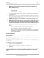
3.2.1.3.1 Reading out vehicle data via the connection manager
Another option for starting the automatic read out of vehicle data is via the "Connection manager"
mask. You can call it up at any time via the symbol bar (Chapter 3.6.4).
3.2.1.4 Basic features
If the vehicle identification number is unknown, you can alternatively use the "Basic features" tab.
V 1.0/2008-11-04
www.bmwicom.net
Copyright © BMW AG 2008
BMW Group
Page 38
Documentation/ISTA User's Manual
Fig. 3.10
of
132
"Basic features" tab
► How to identify a vehicle via its basic features:
◊
Click the "Identification" main menu. The "VIN" tab will be selected.
◊
Click on the "Basic features" tab.
◊
If required, choose another basic feature from the left-hand
"Basic features" selection list.
◊
Define the contents for the basic feature by selecting an entry from the central list.
◊
If necessary, repeat the entry with other basic features (the predefined sequence does not
have to be observed) or click the "Accept" button.
After the individual basic features, the workshop system only offers items that are compatible with
the previously selected ones. This excludes contradictory entries.
There is no need to enter all available basic features. However, you must define at least one. The
more completely you specify the basic features, the more precisely the workshop system can select
the matching documents.
NOTE
Without specification of E-designation and in some cases the model year and month,
vehicle-specific searches for the function structure, component structure, or service
function structure cannot be performed!
V 1.0/2008-11-04
www.bmwicom.net
Copyright © BMW AG 2008
BMW Group
Page 39
Documentation/ISTA User's Manual
of
132
NOTE
It is not possible to manually select the features for security vehicles.
Security vehicles can only be identified via the VIN.
After entering the basic features a check is performed to see whether an operation with the
specified features is already present in the operations list and a selection is offered. If the selected
basic feature combination is unknown, a new operation is automatically created (also see Chapter
3.7.1.5).
Incomplete entry of basic features
If you click the "Accept" button without having defined all "Basic features", a popup window
appears containing a system message. Acknowledge the message with "Continue" to end the
vehicle selection procedure or return to selection of the basic features with "Cancel".
Fig. 3.11
"System message incomplete entry of basic features" popup window
On completion of vehicle identification, the display switches over to the "Operation details" menu
(Chapter 3.2.2.1).
V 1.0/2008-11-04
www.bmwicom.net
Copyright © BMW AG 2008
BMW Group
Page 40
Documentation/ISTA User's Manual
3.2.2
of
132
Operation information
"Operation information" is automatically accessed after the vehicle identification is completed. This
is where information on the current operation and the identified vehicle is displayed.
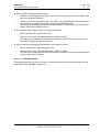
3.2.2.1 Operation details
If you have completed vehicle selection or if you access the "Identification" menu from an ongoing
operation, the workshop system automatically displays the "Operation details" tab. This is where
you can view general information to identify the vehicle, for example:
◊
Basic features of vehicle
◊
Technical actions on the identified vehicle with status "open", special defect code and
name (title)
◊
Customer statement (customer complaints).
In the header, you will see the vehicle identification number ("VIN") and the determined basic
features of the vehicle. If you select a vehicle via "Basic features", the basic features that you
entered appear in the header.
Prerequisites:
◊
Vehicle identification (Chapter 3.2).
◊
Before the "Technical actions" can be displayed, the vehicle identification number must
be known and an online connection must be established to BMW headquarters.
Fig. 3.12
"Operation information" menu, "Operation details" tab
V 1.0/2008-11-04
www.bmwicom.net
Copyright © BMW AG 2008
BMW Group
Page 41
Documentation/ISTA User's Manual
of
132
The following buttons are available in the action line:
◊
Perform vehicle test: For manual vehicle identification, this button starts the vehicle test
(Chapter 3.3). With automatic vehicle identification, the vehicle test proceeds in the
background and the button only switches over to the control unit tree.
Note for the E21 – E31 Series: The BST mode is called up! You can find more information
on this mode in Chapter 3.5.2.2.
◊
Information search: See section 3.4.1.
3.2.2.2 Vehicle details
You can obtain more detailed information on the selected vehicle by clicking the "Vehicle details"
tab, such as series equipment and special equipment. This information will be retrieved from a
central database and indicates the vehicle status in each case on delivery from the factory.
Retrofitted equipment or installations are not taken into account. Not all information is available for
vehicles made before 1992. Therefore valid values cannot be displayed in all fields. Such fields are
displayed without a value.
Prerequisites:
◊
Vehicle identification via "VIN" (Chapter 3.2.1.2)
◊
Online connection to BMW AG (via ISPA Broker).
Fig. 3.13 "Operation information" submenu, "Vehicle details" tab (no current screenshot)
V 1.0/2008-11-04
www.bmwicom.net
Copyright © BMW AG 2008
BMW Group
Page 42
Documentation/ISTA User's Manual
of
132
NOTE
The standard series equipment and special equipment listed in the "Vehicle details“
mask corresponds to the state of the vehicle as it left the factory and may diverge from
the present state of the vehicle!
V 1.0/2008-11-04
www.bmwicom.net
Copyright © BMW AG 2008
BMW Group
Page 43
Documentation/ISTA User's Manual
of
132
3.2.2.3 Repair history
A list of previously performed workshop jobs on the vehicle can be obtained by clicking the
"Repair history" tab.
Prerequisites:
◊
Vehicle identification via "VIN" (Chapter 3.2.1.2)
◊
Online connection to BMW AG (ISPA Broker).
Fig. 3.14
"Operation information" submenu, "Repair history" tab (screenshot in German)
NOTE
At present this function is only available in Germany!
The following buttons are available in the action line:
◊
Display: Access the "Repair history detailed view" window for the highlighted repair job.
The detailed view lists all job items for the selected workshop visit. The item No., job
number, designation, number of flat rates, local job number, part number, local part number
and part designation are displayed for each job item.
◊
Display all: adapts the widths of all columns to their maximum text lengths. If you
click the button a second time, the workshop system returns the columns to their
initial widths. If required, a horizontal progress bar is displayed.
V 1.0/2008-11-04
www.bmwicom.net
Copyright © BMW AG 2008
BMW Group
Page 44
Documentation/ISTA User's Manual
◊
of
132
Close: closes the "Repair history detailed view" window. The "Repair history" tab
will be displayed.
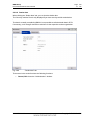
3.2.2.4 Operations report
By clicking the "Operations report" tab you will receive a report on the ongoing operation with
the dealer data and the data on the respective vehicle. The report is constantly updated during
the execution of the operation.
Fig. 3.15
"Operation information" submenu, "Operations report" tab
The screen display for the operations reports differs from the printed report because of its
colored displays.
The following information blocks are contained in the operations report:
◊
Dealer data
◊
Vehicle data
◊
Customer complaints (customer's own words, customer's quote, qualified)
◊
Start of operation (date, time)
◊
First vehicle test
◊
Fault memory data from the first vehicle test
◊
Test plan diagnosis start (first test plan)
◊
Test plan diagnosis end (last test plan)
V 1.0/2008-11-04
www.bmwicom.net
Copyright © BMW AG 2008
BMW Group
Page 45
Documentation/ISTA User's Manual
of
◊
Information object selected (title, document type, identifier)
◊
Process object selected (title, start, end time stamp, identifier) plus process steps
(inputs/outputs, ECU functions, measuring instruments actions)
◊
Vehicle test diagnosis end (last vehicle test)
◊
Fault memory data (last vehicle test)
132
Print operations report or diagnostic report
► How to print out an operations report:
◊
Click on the "Print" icon.
◊
Select the "Document" option.
◊
Click on the "OK" button.
FBM reports (FASTA)
FBM reports are always automatically produced in the background when an operation is terminated
or interrupted (exception: OSS) and forwarded to BMW AG. In offline mode, the FBM reports are not
created until the system is synchronized with the server.
3.3 Vehicle test
The vehicle test determines the control units installed in the vehicle and their variants, as well as
their special equipment. Furthermore the vehicle test reads the diagnostic and service-related data
from the control units and generates test plans, which become part of the service procedure. In the
first vehicle test within an operation, vehicle-specific FASTA data are determined and logged.
Prerequisites for the vehicle test:
◊
Vehicle identification (Chapter 3.2)
With manual vehicle identification the primary vehicle test starts by clicking on the "Perform vehicle
test" button in the "Operation details" mask. With automatic vehicle identification, the vehicle test
runs in the background of the "Operation details" mask. By clicking the "Perform vehicle test"
button, the workshop system switches to the "Control unit tree" mask and runs the vehicle test in
the foreground.
If required, for example after repair or modification work, you can restart the vehicle test manually.
NOTE
For the E21 - E31 Series, there is no vehicle test available. Clicking the "Perform
vehicle test" button in the "Operation details" mask (Chapter 3.2.2.1) takes you to BST
mode (Chapter 3.5.2.2). Furthermore, the "Vehicle test" and "Activities – Guided
troubleshooting" menus are inactive.
V 1.0/2008-11-04
www.bmwicom.net
Copyright © BMW AG 2008
BMW Group
Page 46
Documentation/ISTA User's Manual
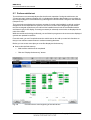
3.3.1
of
132
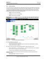
Control unit tree
The "Control unit tree" mask shows the configuration of the control units. While the vehicle test is
running, the symbol of the directly accessed control unit will be displayed in the color of the mask.
The vehicle test identifies the installed control devices and reads out the fault memory and the
control device characteristics. At the end of the vehicle test, the symbols in the control unit tree
indicate the test result by means of the following colors:
◊
Green: control unit is responding
◊
Yellow: control unit is not responding
◊
Gray: control unit is not installed.
Fig. 3.16
Control unit tree (after vehicle test)
► How to repeat the vehicle test:
◊
Click the "Start vehicle test" button.
In the "Control unit tree" mask, the control unit symbols are updated again according
to the vehicle test just completed.
► Thus the vehicle test starts automatically behind the "Operation details" mask:
◊
Select "Identification" -> "Vehicle selection" -> "Read out vehicle data" in the navigation
area to perform an automatic vehicle identification.
◊
Continue as described with the "Read out vehicle data" tab (Chapter 3.2.1.3).
The buttons in the action line do not become active until after the vehicle test, and have the
following functions:
◊
Start vehicle test: repeats the vehicle test.
V 1.0/2008-11-04
www.bmwicom.net
Copyright © BMW AG 2008
BMW Group
Page 47
Documentation/ISTA User's Manual
of
◊
Call up ECU functions: switches to the "Control unit functions" mask (Chapter 3.3.1.1).
◊
Display fault memory: switches to the "Fault memory list" mask (Chapter 3.4.2.1).
132
3.3.1.1 Control unit functions
The control unit functions become accessible if at least one vehicle test has been completed for the
ongoing operation (Chapter 3.3).
► How to call up the control unit functions for a control device:
◊
Click on a control device in the control unit tree;
◊
or
◊
Select a control unit from the control unit list.
◊
Click the "Call up ECU functions" button in the action line. The following control unit
functions can be displayed in three different tabs:
- Identification
- Diagnostic query
- Component activation
◊
Return to the original mask by clicking the "Close" button.
3.3.1.1.1 Identification
The control unit function "Identification" is selected by clicking the "Call up ECU functions" button.
Fig. 3.17
"Identification" tab
V 1.0/2008-11-04
www.bmwicom.net
Copyright © BMW AG 2008
BMW Group
Page 48
Documentation/ISTA User's Manual
of
132
The "Identification" tab contains the following data:
◊
ECU Name: name of the control unit version.
◊
ECU Status: communication status ("ECU responding", "ECU not responding").
◊
ECU Information: this is where the ECU readout specifications are listed.
The buttons in the action line have the following meanings:
◊
ECU Test: reads the ECU data out again. A progress display keeps you up-to-date with
progress.
◊
Close: closes the display of the control unit functions and returns to the original mask.
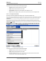
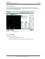
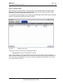
3.3.1.1.2 Diagnostic query
Access the diagnostic query by clicking on the "Diagnostic query" tab.
The content range is divided into two sections: The "Control unit functions" table lists the sensors
belonging to the control unit and the "Function and status display" area indicates the current signal
status.
Depending on the control unit, several sensor may be combined in groups whose entries you can
open by clicking so that you can reach the individual sensors. Multiple selection is possible.
Fig. 3.18
"Diagnostic query" mask
V 1.0/2008-11-04
www.bmwicom.net
Copyright © BMW AG 2008
BMW Group
Page 49
Documentation/ISTA User's Manual
of
132
The buttons in the action line have the following meanings:
◊
Undo all: undoes the entire selection in the table.
◊
Undo: undoes the last selection in the table.
◊
Query status: switches the cyclical update of the display on or off.
◊
Close: closes the display of the control unit functions and returns to the original mask.
3.3.1.1.3 Component activation
Access the component activation by clicking on the "Component activation" tab
The content range is divided into two sections: The "Control unit functions" table lists the actuating
elements and the "Function and status display" area indicates the current status of an actuated
component.
Depending on the control unit, several actuating elements may be combined in groups whose
entries can be opened by clicking so that you can reach the individual actuating elements. Multiple
selection is not possible.
Fig. 3.19
"Component activation" mask
The buttons in the action line have the following meanings:
◊
Undo all: undoes the entire selection in the table.
◊
Undo: undoes the last selection in the table.
◊
Actuate component: displays the associated function name and the execution of the
function in the "Function and status display" area.
V 1.0/2008-11-04
www.bmwicom.net
Copyright © BMW AG 2008
BMW Group
Page 50
Documentation/ISTA User's Manual
◊
3.3.2
of
132
Close: closes the control unit functions display and returns to the original mask.
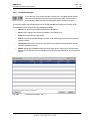
Control unit list
The control unit list is another way of presenting the control unit tree. You can call up the list by
clicking the tab as soon as the first vehicle test is completed and repeat it from the vehicle test. The
individual columns the following meaning:
◊
Status: This is where the status of communication with the control unit of the vehicle test is
updated.
◊
Abbr.: The abbreviation for the respective control unit.
◊
Control unit name: A short description of the control unit appears at the beginning. When
the vehicle test is performed, the control unit name is replaced by a complete description.
Fig. 3.20
"Control unit list" mask
The buttons in the action line have the following functions after completion of the vehicle test:
◊
Start vehicle test: repeats the vehicle test.
◊
Call up ECU functions: only active if a control unit is previously selected. Changes over to
the "Control unit functions" mask (Chapter 3.3.1.1).
◊
Display fault memory: changes over to the "Fault memory" mask (Chapter 3.4.2.1).
V 1.0/2008-11-04
www.bmwicom.net
Copyright © BMW AG 2008
BMW Group
Page 51
Documentation/ISTA User's Manual
of
132
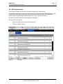
3.4 Activities
3.4.1
Information search
Three different structure searches (Product structure, Function structure, Components and signals)
and a text search are available in the "Information search" menu.
Prerequisites:
◊
Vehicle identification (Chapter 3.2).
3.4.1.1 Product structure
In the product structure menu, you can search for information in the main and subgroups. In the
left-hand column, the required product group can be selected. The previously selected elements
are clearly displayed in the "Selected structure elements" column.
Fig. 3.21
"Product structure" tab
The elements in the info line have the following functions:
◊
Hits: states how many elements satisfy the present search criteria. If a product group has
not been selected, then the number of hits is "0".
◊
Filter: displays the filter status. If you have not changed the filter setting, then the "Default"
status appears; otherwise it is "User-defined".
V 1.0/2008-11-04
www.bmwicom.net
Copyright © BMW AG 2008
BMW Group
Page 52
Documentation/ISTA User's Manual
of
132
The buttons in the action bar have the following functions:
◊
Undo all and Undo: You may reverse individual or all operating steps so that you can enter
new search criteria.
◊
Filter: You can call up a window with which you limit the search to certain time periods or
information types, e.g. circuit plans or repair instructions (Fig. 3.22). These filter settings
are taken into account in the search.
◊
Start search: Start search using the selected criteria.
► How to search in the product structure:
◊
Select one element in the left-hand selection list. Depending on the item chosen, in some
cases further selection lists with additional options will be displayed, via which you can
further refine your search criteria.
◊
Further restrict the search criteria in the left-hand list. The previously selected items are
clearly shown in the "Selected structure elements" column.
◊
If necessary, you can refine the selection using the "Filters" button.
◊
Click the "Start search" button.
When the search has been completed, the ISTA workshop system switches over to the "Service
plan" and displays the hit list (Chapter 3.5.1).
3.4.1.1.1 Filters
The "Filter settings" window can be accessed via "Information search", "Service function" (Chapter
3.4.3) or "Test plan" (Chapter 3.5.2) by clicking the "Filters" button in the respective window. You
can change the filter settings for information types and/or define a time slot for the latest update of
the documents.
In the default setting, the information types available in the respective search mode are preselected.
These preselected as well as the manually selected information types are marked with a cross.
V 1.0/2008-11-04
www.bmwicom.net
Copyright © BMW AG 2008
BMW Group
Page 53
Documentation/ISTA User's Manual
Fig. 3.22
of
132
"Filter settings" tab
The buttons in the action bar have the following functions:
◊
Cancel: The window is closed and the changed filter settings are not adopted. The filter
status does not change and remains in the previous status ("Default" or "User defined").
◊
Default settings: resets the filter to the preset values.
◊
Keyboard: displays the on-screen keyboard.
◊
Select all: marks all information types.
◊
Selecting nothing: removes all selections from the information types.
◊
OK: starts the search.
► How to change the filter settings for information types:
◊
Click on a specific information type that you would like to select or deselect or else click on
the buttons "Select all" or "Select nothing".
◊
Select or deselect individual information types as required.
◊
Click the "OK" button. The workshop system adopts the selected filter settings and closes
the popup window. The number of hits is adapted accordingly, the filter status in the
information line changes from "Default" to "User defined"
► How to define the period for the last update of the information type:
◊
Define a date as the lower limit in the "Time period from:" field. If appropriate, use the onscreen keyboard. The date must comply with the order stated in brackets under "Last date
change".
V 1.0/2008-11-04
www.bmwicom.net
Copyright © BMW AG 2008
BMW Group
Page 54
Documentation/ISTA User's Manual
of
132
◊
Define a date as the upper limit in the "Time period to:" field. The date entered has to be
later than the one entered in the "Time period from:" field.
◊
Click the "OK" button. The workshop system adopts the selected filter settings and closes
the popup window. The number of hits is adapted accordingly, the filter status in the
information line changes from "Default" to "User defined"
If you click the "Select nothing" button, then the entered period will be deleted.
3.4.1.2 Function structure
In the "Function structure" window, you can search on several levels by selecting the function
groups and functions.
Fig. 3.23
"Function structure" tab
This operation is analogous to that for "Product structure" (Chapter 3.4.1.1).
V 1.0/2008-11-04
www.bmwicom.net
Copyright © BMW AG 2008
BMW Group
Page 55
Documentation/ISTA User's Manual
of
132
3.4.1.3 Components and signals
The "Components and signals" tab can be used to search for documents that relate to a specific
component or signal.
Fig. 3.24
"Components and signals" tab
This operation is analogous to that for "Product structure" (Chapter 3.4.1.1).
V 1.0/2008-11-04
www.bmwicom.net
Copyright © BMW AG 2008
BMW Group
Page 56
Documentation/ISTA User's Manual
of
132
3.4.1.4 Text search
As an alternative to a structure search, you can also use a text search.
Prerequisites:
◊
Vehicle identification (Chapter 3.2)
Fig. 3.25
"Text search" tab
► How to search for information with full text:
◊
Select "Activities" in the main menu.
◊
Select "Information search" in the submenu.
◊
Select the "Text search" tab.
◊
Restrict the search to document titles, documents (texts), or document numbers.
◊
Enter the text string in the "Search term" field. If appropriate, use the on-screen keyboard
(Chapter 1.8.7). If necessary, you can refine the search using the "Filters" button.
◊
Start the search with the "Start search" button.
When the search has been completed, the ISTA workshop system switches over to the
"Service plan" function and displays the hit list (Chapter 3.5.1).
V 1.0/2008-11-04
www.bmwicom.net
Copyright © BMW AG 2008
BMW Group
Page 57
Documentation/ISTA User's Manual
of
132
3.4.1.4.1 Additional general information on the text search
The text search is not case-sensitive. Entering "Engine" or "engine", for example, produces the
same result in the hit list.
If several terms are entered and are separated by space characters, then the terms are linked by the
operator AND in the search. Only those hits that contain all of the search terms entered are
displayed.
Each search term must contain at least two characters.
3.4.1.4.2 Additional information on the text search in headings
If you search for the term "Engine" in the title, for example, then all documents whose title includes
the term "Engine" will be listed. Furthermore, all documents which have the term anywhere in their
title will be added to the hit list, for example "Gasoline engine", "Engine mounting", "Electric
engine".
3.4.1.4.3 Additional information on the text search in the document
If you search in the document for the term "Engine", for example, only documents that contain this
term will be found. Documents containing terms such as "engine mounting" or "gasoline engine"
will not be included in the hit list. Numbers will not be taken into account when performing a text
search in the document.
Specific information for individual markets is contained in the data packages in the form of pdf files.
These can be displayed in ISTA. It is not possible to perform a text search in these pdf files. Title
and document number searches are also supported in these documents.
3.4.1.4.4 Additional information on the text search by document number
For searches by document number, the entered character sequence is only searched at the
beginning of the document number. If the search term "123“ is entered, then documents such as
"123456“ will appear in the hit list. Documents such as "456123“ or "51234“ will not appear in the
hit list.
3.4.1.4.5 Additional information on text searches by component code and signal name
In the wiring diagrams codes are used for components and signals such as "A149a“ for a control
device or "X1108“ for a ground connection. The text search can only be used to find these codes in
the title. All the documents are displayed in the hit list that contain the entered code in their title,
e.g. "A149a“ or "X1108“. Searches by component code within the document are not possible. The
same applies for searches for engine codes such as "M54“.
V 1.0/2008-11-04
www.bmwicom.net
Copyright © BMW AG 2008
BMW Group
Page 58
Documentation/ISTA User's Manual
3.4.2
of
132
Assisted troubleshooting
3.4.2.1 Fault memory
The "Fault memory" tab displays the fault memory entries read out from the control units in the
vehicle test (Chapter 3.3). There are several ways to reach this tab:
◊
On completion of the vehicle test in the "Control unit tree" or "Control unit list" tabs by
clicking the "Display fault memory" button.
◊
By selecting "Activities" -> "Guided troubleshooting" -> "Fault memory" in the navigation
area.
Fig. 3.26
"Fault memory" tab
The fault memory list contains the following columns:
◊
Code: The fault code or the fault number appears in hexadecimal form.
◊
Description: This column contains a description of the fault location.
The following buttons are available in the action line:
◊
Display detail table: Choose a line and then click this button. You will then obtain
the detailed information on a fault (Fig. 3.27). If there are several results for the ambient
conditions, then only the first and the last information block will be displayed.
◊
Start quick delete: This function is only active after a completed vehicle test
(Chapter 3.3). In each identified control unit, the fault memory is deleted and then
reread. OBD control units are only deleted if a fault is set in your fault memory.
◊
Display all: adapts the widths of all columns to their maximum text lengths. If you
click the button once more, the workshop system sets the columns to their initial widths.
If required, a horizontal progress bar is displayed.
V 1.0/2008-11-04
www.bmwicom.net
Copyright © BMW AG 2008
BMW Group
Page 59
Documentation/ISTA User's Manual
◊
of
132
Calculate test plan: starts the calculation and display of the test plan with the existing
fault memory entries and selected diagnostic symptoms (Chapter 3.5.2).
Display detail table
Fig. 3.27
"Fault details" mask
The "Fault details" mask contains supplementary descriptions on a fault code:
◊
Control unit: the name of the control unit version will be displayed.
◊
Fault memory: displays the fault code in hexadecimal form and, below this, fault location.
◊
Vehicle data: the fault status as well as details on the ambient conditions will be displayed
(if available).
The buttons in the action line have the following functions:
◊
Update: The detailed information will be reread and displayed.
◊
Close: closes the window and returns to the "Fault memory" mask.
V 1.0/2008-11-04
www.bmwicom.net
Copyright © BMW AG 2008
BMW Group
Page 60
Documentation/ISTA User's Manual
of
132
3.4.2.2 Fault pattern
The "Fault pattern" tab can be used to select fault patterns from a functional structure on many
levels.
They supplement the read-in fault memory entries and are taken into account in test plan
calculation. The tab is not active unless the fault memories of the identified vehicle are being read
out. You should select the fault patterns independently of the customer's complaints about the
vehicle. Otherwise, only the saved faults will be taken into account when the test plan is created.
Especially for complaints apart from the vehicle's electric system, the selection of fault patterns is
especially important for assuring a successful diagnosis.
Select "Activities" -> "Guided troubleshooting" -> "Fault pattern" in the navigation area.
In the left-hand section of the content range, you can select the fault pattern from a hierarchical
structure: start with the uppermost, most general level and work your way down to an exact
description of the fault pattern. On the right side of the mask, the path through the selection
levels is logged.
Define the fault pattern as precisely as possible; otherwise, the test plan (Chapter 3.5.2)
generates an unnecessarily high number of test suggestions.
Fig. 3.28
"Fault pattern" tab
The following buttons are available in the action line:
◊
Undo all: deletes the existing selection and returns to the uppermost level.
◊
Undo: undoes the last selected step.
◊
Accept fault pattern: The previously selected symptom path (at least one level) is saved
as a basis for subsequently calculating the test plan. The tab then returns as the "Undo all"
button to the uppermost selection level. The selected fault pattern is then saved when you
quit the
"Fault pattern" tab.
V 1.0/2008-11-04
www.bmwicom.net
Copyright © BMW AG 2008
BMW Group
Page 61
Documentation/ISTA User's Manual
of
◊
Display fault patterns: When clicking this button, a popup appears containing all the
previously saved fault patterns (Fig. 3.29).
◊
Calculate test plan: starts the calculation and display of the test plan with the existing
diagnostic symptoms (Chapter 3.5.2).
132
3.4.2.2.1 Selected fault patterns
The popup window in the "Fault pattern" mask shows the previously saved fault patterns.
Fig. 3.29
"Fault pattern" tab with "Selected fault patterns" popup
The following buttons are available in the action line:
◊
Cancel: The popup window will be closed; the changes made will not be saved.
◊
Delete: deletes the selected entry.
◊
OK: The popup window will close; the changes made will be saved.
► How to save a fault pattern and include it in the test plan :
◊
Compile the desired fault pattern in the content range by navigating through the
available levels and selecting the suitable terms or phrases.
◊
If appropriate, click the "Display fault patterns" button and confirm with "OK".
◊
Click the "Calculate test plan" button.
V 1.0/2008-11-04
www.bmwicom.net
Copyright © BMW AG 2008
BMW Group
Page 62
Documentation/ISTA User's Manual
3.4.3
of
132
Service function
The "Service functions" area covers all service-related jobs.
3.4.3.1 Service functions
You can search for service-relevant jobs under the "Service functions" tab, e.g. when
searching a function description.
Prerequisites:
◊
Vehicle identification (Chapter 3.2)
Fig. 3.30
"Service functions" tab
This operation is analogous to that for "Product structure" (Chapter 3.4.1.1).
V 1.0/2008-11-04
www.bmwicom.net
Copyright © BMW AG 2008
BMW Group
Page 63
Documentation/ISTA User's Manual
3.4.4
of
132
Workshop/Operating fluids
The search functions in the "Workshop/Operating fluids" area are vehicle-independent
(or operation-independent, respectively); you can use these functions without previously having to
identify a vehicle.
3.4.4.1 Workshop equipment
The "Workshop equipment" tab can be used to search for general information on workshop
equipment.
Prerequisites:
◊
none
Fig. 3.31
"Workshop equipment" tab
This operation is analogous to that for "Product structure" (Chapter 3.4.1.1).
However, no filter functions are available in this case.
V 1.0/2008-11-04
www.bmwicom.net
Copyright © BMW AG 2008
BMW Group
Page 64
Documentation/ISTA User's Manual
of
132
3.4.4.2 Operating fluids
The "Operating fluids" tab can be used to obtain non-vehicle specific information on approved
fuels, lubricants, coolant additives, antifreezes, cleaning agents, etc.
Prerequisites:
◊
none
Fig. 3.32
"Operating fluids" tab
This operation is analogous to that for "Product structure" (Chapter 3.4.1.1).
However, no filter functions are available in this case.
V 1.0/2008-11-04
www.bmwicom.net
Copyright © BMW AG 2008
BMW Group
Page 65
Documentation/ISTA User's Manual
of
132
3.4.4.3 Text search
You can enter character strings for vehicle-independent information via document title, document
contents or document numbers.
Prerequisites:
◊
none
Fig. 3.33
Example of "Text search" tab and "Workshop/Operating fluids"
► How to search for a random term:
◊
From the displayed options, choose whether you want to search for a document title,
document contents, or a document number.
◊
Enter the text or number sequence that you want to look up in the "Search term" field.
If appropriate, use the on-screen keyboard. Only part of a longer term has to be entered
as search text, e.g. "Doc" for "Document".
◊
Click the "Start search" button.
When the search has been completed, the ISTA workshop system switches over to the "Service
plan" and displays the hit list (Chapter 3.5.1).
You can find additional information on the title or document-specific text search in Chapter 3.4.1.4.
V 1.0/2008-11-04
www.bmwicom.net
Copyright © BMW AG 2008
BMW Group
Page 66
Documentation/ISTA User's Manual
3.4.5
of
132
Measuring devices
The measuring devices (Multimeter, Oscilloscope, Signals) are component parts of the ISTA
workshop system. The corresponding measuring devices hardware, as well as the periodic
measurement data logging, preparation of information, and provision of the results, is performed by
the IMIB connected via LAN.
► How to start the measuring devices:
◊
Call up the measuring devices via the "Activities" –> "Measuring devices" selection
in the navigation area.
◊
Choose the "Measuring devices" tab. The "Connection manager" mask appears.
◊
Select the desired IMIB and click the "Set up connection" button.
The "Measuring devices" tab will then appear with the preset "Multimeter" preset tab.
Fig. 3.34
"Measuring devices" tab
V 1.0/2008-11-04
www.bmwicom.net
Copyright © BMW AG 2008
BMW Group
Page 67
Documentation/ISTA User's Manual
Fig. 3.35
of
132
"Connection manager" mask
Switching to another tab
When switching between the measuring devices tabs, the most recently made setting will be
retained.
V 1.0/2008-11-04
www.bmwicom.net
Copyright © BMW AG 2008
BMW Group
Page 68
Documentation/ISTA User's Manual
of
132
3.4.5.1 Multimeter
The "Multimeter" tab contains display and control elements for two multimeters that are separately
displayed in the content range, divided by a green line. Besides individual measurements, the
devices also support parallel measurement via Probe 1 and Probe 2 for resistance, direct/alternating
voltage, direct/alternating current, as well as the diode test. Furthermore, parallel measurements
with Probe 1 or 2, as well as a sensor (kV clip/RZV cable [resting voltage cable], clip-on ammeter,
pressure sensor, or temperature sensor), are possible.
Each multimeter consists of a display area (left) and a settings area (right). With the "Quit measuring
devices" button in the action line, you can return to the "Measuring devices" tab (Fig. 3.34).
Fig. 3.36
"Multimeter" mask
3.4.5.1.1 Display range
The display area shows the measured value with its physical unit of measurement highlighted in
color. The measured values of Multimeter 1 (connected with Probe 1 by default) are displayed in
green; Multimeter 2 (connected with probe 2 by default) displays measured values in red. Under the
display area, there are two buttons with the following functions:
◊
MIN/MAX: If you click this button, the two limit values are shown at the bottom left of the
display window.
"MIN" corresponds to the lowest value in the period of measurement, e.g.
"Imin = 6 A". "MAX" shows the highest value, e.g. "Imax = 7 A".
◊
Freeze-frame: This function "freezes" the measurement; the last measurement is thus
retained. You can also trigger the freeze-frame function at the probe and then read the value
at the tester. If you click the button a second time, the measured values continue to be
displayed.
V 1.0/2008-11-04
www.bmwicom.net
Copyright © BMW AG 2008
BMW Group
Page 69
Documentation/ISTA User's Manual
of
132
3.4.5.1.2 Range
The setting range is located at the bottom right of the mask, divided into an area for Multimeter 1
(top) and Multimeter 2 (bottom). At the top, there are six buttons for selecting a measurement
source (probes and sensors). Under these are the "Mode" zones for setting the measurement type
and "Range" for setting the measurement range.
3.4.5.1.2.1 Source (measurement source)
The following measurement sources are used:
◊
Probe 1: for resistors, direct/alternating voltage, direct/alternating current, diode tests.
◊
Probe 2: for resistors, direct/alternating voltage, direct/alternating current, diode tests.
◊
kV clip/RZV cable: for high voltage measurements in ignition systems.
◊
Clip-on ammeter: for direct and alternating current.
◊
Pressure sensor: for pressure measurements, e.g. cylinder 1 compression.
◊
Temperature sensor: for temperature measurements in liquids, e.g. oil temperature.
After the source has been selected, the button will be displayed in the color of the mask.
3.4.5.1.2.2 Mode
The possible settings change according to the selected source. After selection of a mode, e.g.
"DC V", it is highlighted in the color of the mask. The abbreviations mean:
◊
Ω: Resistor measurement
◊
AC V: Alternating voltage measurement
◊
DC V: Direct voltage measurement
◊
AC A: Alternating current measurement
◊
DC A: Direct current measurement
◊
-►І- : Diode test
3.4.5.1.2.3 Range
The range changes according to the source. The measuring device will automatically be set to the
highest measurement range by default; however, you can manually adjust it if required.
NOTE
If the displayed measurement value lies outside the manually selected range, the
display changes to "++++" or "----".
V 1.0/2008-11-04
www.bmwicom.net
Copyright © BMW AG 2008
BMW Group
Page 70
Documentation/ISTA User's Manual
of
132
► How to perform a resistor measurement with Multimeter 1:
◊
Select the source "Probe 1".
◊
Select the "Ω" mode.
◊
Connect the DSO cable 1 to the IMIB.
◊
Connect the probes to the resistance.
◊
Perform the measurement.
► How to perform measurements on two signals simultaneously, so that you can measure battery
voltage and current, for example:
◊
Select the source "Clip-on ammeter" on Multimeter 2.
◊
Select the "DC A" mode on Multimeter 2.
◊
Select the range matching the selected clip-on ammeter on Multimeter 2.
◊
Select the source "Probe 1" on Multimeter 1.
◊
Select the "DC V" mode at Multimeter 1.
◊
Connect the clip-on ammeter to the IMIB.
◊
Connect the clip-on ammeter to the vehicle's minus lead.
◊
Connect the DSO cable 1 to the IMIB.
◊
Connect the probes to the battery poles.
◊
Click the button on the probe to freeze the measurement.
◊
Evaluate the measurement.
V 1.0/2008-11-04
www.bmwicom.net
Copyright © BMW AG 2008
BMW Group
Page 71
Documentation/ISTA User's Manual
of
132
3.4.5.2 Oscilloscope
Two time-dependent variables are measured with the dual channel oscilloscope. The screen
displays measured and processed curves and results in the left (display) area. The IMIB settings
can be adjusted in the right (setting) area.
Fig. 3.37
"Oscilloscope" tab
3.4.5.2.1 Display area
The display area is divided into:
◊
Graph display: for graphical plots of curves.
◊
Measured value display: for numerical display of voltage and time values.
V 1.0/2008-11-04
www.bmwicom.net
Copyright © BMW AG 2008
BMW Group
Page 72
Documentation/ISTA User's Manual
of
132
3.4.5.2.1.1 Graph display
With linear scaling, the graph display is divided into a 10 x 8 grid. With logarithmic scaling,
the y-axis is divided into 4 groups of 10; the x-axis remains unchanged.
2nd Gridline
Progress
8th Gridline
Reference
cursor
Trigger
mark
Differential
cursor
y-axis
x-axis
Fig. 3.38
Graph display
Depending on the application, a trigger mark, two cursors and a progress bar on the top edge
will appear in the graph plot.
So that you can distinguish between curves and correctly assign their settings, the curve from
Channel 1 (CH1) is green and the curve from Channel 2 (CH2) is red. Cursors, trigger marks and
progress bars are white.
The frequency of graph updates depends on the sampling rate set on the oscilloscope. The
following presets apply for individual areas:
◊
Sampling rate < 100 µs: Time interval 10 ms.
◊
100 µs ≤ sampling rate < 1 s: Time interval 300 ms.
◊
Sampling rate ≥ 1 s: Record mode (Record). The curve progresses in linear steps
of approx. 4 pixels from right to left and is recorded at the same time.
V 1.0/2008-11-04
www.bmwicom.net
Copyright © BMW AG 2008
BMW Group
Page 73
Documentation/ISTA User's Manual
of
132
3.4.5.2.1.2 Measured value display
Below the graph display, there is a display consisting of 3 columns for numerical values
and status messages. This the set measurement ranges are displayed.
Fig. 3.39
Measured value display
The meaning of the displays is described in the following chapter.
3.4.5.2.2 Range
The controls for setting the oscilloscope are located on the right-hand side of the mask.
Fig. 3.40
Range
The controls are arranged in five settings:
◊
Cursor (exclusively arrow keys for reference and difference)
◊
Display
◊
Time
◊
Channel (channels CH1 and CH2)
◊
Trigger
V 1.0/2008-11-04
www.bmwicom.net
Copyright © BMW AG 2008
BMW Group
Page 74
Documentation/ISTA User's Manual
of
132
3.4.5.2.2.1 Cursor
The "Cursor" settings group contains the following buttons:
◊
CH1, CH2: When clicking and locking a button, the two cursors will appear in the second
and eighth grid line of the graph display for the respective curve (reference and difference,
see Fig. 3.38). The cursors can only be displayed for one channel respectively: For example,
if you lock the "CH2" button, then the "CH1" button will be simultaneously unlocked. If you
click the same button once more, the measuring cursors will be faded out again.
You can move the reference cursor along the x-axis with the two reference arrow keys and
the differential cursor by using the differential arrow keys. The cursors move pixel by pixel;
their speed increases if an arrow key is pressed down for longer. As soon as a cursor
reaches the edge of a measurement curve, the respective arrow key can no longer be
operated.
◊
Coupled: is activated only if one of the "CH1" or "CH2" buttons, is active. If the "Coupled"
button is locked, then the differential cursor moves when the differential cursor is displaced,
maintaining constant spacing. With the differential arrow keys, you can continue to displace
the differential cursor separately. If you hide the cursor for one channel and later show it
again (cursor key locked), the "Coupled" button adopts the most recently displayed state.
The following applications are linked with the cursor function:
◊
◊
Measuring curves: The oscilloscope determines the following points and shows the values
in the measured value display:
◊
Intersection of reference cursor with the curve ("Ref.Cur")
◊
Interface of differential cursor with the curve ("Diff.Cur")
◊
Voltage difference between the reference and differential cursor ("∆Cur").
Output of Set values: When you select the "CH1" or "CH2" button in the cursor settings
group, the following counter values are entered into the measured value display:
◊
Period ("t")
V 1.0/2008-11-04
www.bmwicom.net
Copyright © BMW AG 2008
BMW Group
Page 75
Documentation/ISTA User's Manual
◊
of
◊
Frequency ("1/t")
◊
Sample ratio of selected channel ("t/T")
◊
Time lag between reference and differential cursor ("∆t").
132
Zooming compresses the curves. In compressed mode, you can select and zoom in on a
curve section (see settings in the "Display" group, "Compress" function, in the following
chapter).
3.4.5.2.2.2 Display
The "Display" settings group contains the following buttons:
◊
Log: logarithmic scaling on/off, as default y-values are presented in linear fashion. When
clicking and locking the "Log" button , the y-axis switches to logarithmic scaling in value
ranges up to 4 groups of 10. Negative measurements are zeroed in the logarithmic display.
Clicking the button a second time switches back to linear scaling.
◊
Record: record mode on/off. When clicking and locking the "Record" button, the record
mode (Chapter 3.4.5.2.3) will be started. The process can be interrupted by once again
clicking on the "Record" button. The record mode is automatically stopped in the "Single"
trigger mode if a trigger event occurs (trigger level, ramp). All settings for the "Channel",
"Time" and "Trigger" settings groups are locked. The record mode is only accessible if the
"Compress" button is not locked.
◊
Compress: scales the x-axis over the entire curve.
When clicking and locking the "Compress" button, the x-axis is scaled so that the entire and
most recently recorded curve can be shown in the measured graph display. The "Record"
button and those for the trigger mode (Auto, Normal, Single) are deactivated.
The "Compress" button can only be clicked after a curve has been recorded. Mark a section
of the compressed curve (either Channel 1 or 2) with the reference and differential cursor.
Click the "Compress" button. The oscilloscope zooms in on the marked curve section to
the normal scaling of the x-axis.
By increasing the sampling rate with the "<Time>/Div" arrow keys, you can zoom in further into a
curve section until the curve is completely expanded.
V 1.0/2008-11-04
www.bmwicom.net
Copyright © BMW AG 2008
BMW Group
Page 76
Documentation/ISTA User's Manual
of
132
With the "<Range>/Div" arrow keys, you can extend the curve in the vertical direction. This does not
enhance the resolution, however.
3.4.5.2.2.3 Time
The settings group contains display ranges for the set values and two arrow keys which can be
used to adjust the set values.
◊
Position: You can move the section along the x-axis if the recorded curve can no longer be
completely displayed in the measurement value display. With the arrow keys, you can
zoom in/zoom out the section from 0 to 100% along the saved curve. The longer you
hold the arrow key down, the faster the section moves. The percentage value indicates in
which section of the saved area the section is located.
section
0%
memory range
50 %
100 %
recorded curve
As long as the reference and differential cursors are displayed (with channel CH1 or CH2 in the
"Cursor" settings group selected), the section can only be displaced between the two cursors.
To scroll through the entire memory, you have to deselect both channels in the "Cursor" settings
group.
V 1.0/2008-11-04
www.bmwicom.net
Copyright © BMW AG 2008
BMW Group
Page 77
Documentation/ISTA User's Manual
of
132
The visible section is displayed in the graph display by the size and position of the status bar at the
top of the display.
◊
<Time>/Div: This is where you define the sampling rate. The associated unit, e.g. "ms/Div",
is displayed via the left arrow key.
3.4.5.2.2.4 Channel
This channel settings group has two buttons, "CH1" and "CH2". Each channel has a Source, Offset,
<Range>/Div (Range/Unit) and Coupling display range selection.
◊
Source: The group of sensors. A signal is transmitted to the oscilloscope via a sensor.
Possible sensors are:
◊
Probe 1 and/or 2
◊
kV clip/RVZ cable
◊
50 A or 1000 A clip-on ammeters
V 1.0/2008-11-04
www.bmwicom.net
Copyright © BMW AG 2008
BMW Group
Page 78
Documentation/ISTA User's Manual
◊
3.5 bar or 100 bar pressure sensors
◊
Trigger clamp
◊
Temperature sensor
of
132
Select a sensor with the arrow keys. If the sensor is not yet connected, a corresponding
message appears.
◊
Offset: The signal displayed on Channel 1 or 2 can be respectively overlaid with a constant
component or a DC voltage (offset). The offset value is preset to 0%; you can change the
range ±100% of the y-axis.
◊
<Measurement range>/Div: This setting designates the group of measurement ranges
and depends on the sensor selected. Set the range with the arrow keys; it will be displayed
in the associated display range. The physical unit is above the left-hand arrow key. The set
range is transferred to the y-axis.
◊
Coupling: Signal coupling for the corresponding channel. The following settings are
possible:
◊
GND (Ground): The input is decoupled from the sensor and is grounded.
◊
AC (Alternating Current): Only alternating current components are represent in the
curve.
◊
DC (Direct Current): Alternating and direct current components are represented in
the curve.
The buttons for the non-available coupling types are gray.
3.4.5.2.2.5 Trigger
In the "Trigger" area, you can set the source, the (trigger) position, the trigger value (level), the
slope and the mode. The current trigger position and trigger value are indicated by an arrow, with
the arrow direction indicating slope.
V 1.0/2008-11-04
www.bmwicom.net
Copyright © BMW AG 2008
BMW Group
Page 79
Documentation/ISTA User's Manual
◊
of
132
Source: The group of sensors. A trigger signal is transmitted to the oscilloscope via a
sensor. Possible sensors are:
◊
Probe 1 and/or 2
◊
kV clip/RVZ cable
◊
50 A or 1000 A clip-on ammeters
Select a sensor using the arrow keys. If the sensor is not yet connected, a corresponding
message will appear.
◊
Position: With the arrow keys, you can displace the trigger time along the x-axis between
10% and 90% along the graph display. The default setting is 50%; the signal in this case is
triggered in the middle of the graph display.
◊
Level: With the arrow keys, you set the amplitude at which triggering should occur as a
percentage of the y-axis.
◊
Slope: defines whether triggering should occur on the positive or negative slope, whereby
only one switch ("pos" or "neg") can be activated at one time. If both buttons are inactive,
the trigger is activated whenever the set trigger value is reached, regardless of whether this
occurs on the rising or falling slope.
◊
Mode: Except in record mode, a trigger mode is always active. The default setting is
"Auto".
◊
Auto: If no trigger is set, then an untriggered image will be shown.
◊
Norm: Prerequisite for a display is the availability of a trigger.
◊
Single: Stops the oscilloscope measurement after the first valid trigger signal. If you
click the "Single" button again, the mode is reactivated and recording of another
measuring signal can begin.
3.4.5.2.3 Record mode
In record mode, the measurements are recorded without being triggered continuously and
temporarily stored.
Recording begins when you click the "Record" button. During recording, the latest measurements
are presented in the graph display. The remaining memory capacity is continuously displayed as a
percentage in the measurement display.
The trigger mode cannot be reactivated until the record mode has been stopped by clicking the
"Record" button.
Recording may be stopped by the following events:
◊
Repeated clicking of the Record button
◊
Reaching of the preset trigger level (depending on the trigger mode)
◊
Memory full
After completion (manual or automatic) of data recording, the "Compress" button is activated and
the entire curve along the x-axis is compressed to the width of the graph. Various tools are available
for closer examination of the curve, using cursor settings and the adjustment of values under
"Time".
V 1.0/2008-11-04
www.bmwicom.net
Copyright © BMW AG 2008
BMW Group
Page 80
Documentation/ISTA User's Manual
of
132
3.4.5.2.4 Action line
The action line contains the following buttons:
◊
Save settings: You can save oscilloscope settings. Saved settings are stored on the ISIS
workshop server and are thus available on every ISID that is linked to the respective ISIS in
online mode. You start the operation by selecting the "Save settings" button in the action
line. The "Save oscilloscope settings" mask appears. Enter a name in the "Save under" field
under which the settings should be saved. The workshop system checks whether the name
has already been assigned.
Fig. 3.41
◊
"Save oscilloscope settings" mask (no current screenshot)
Load/delete settings: The button is only active if oscilloscope settings have been saved.
You can load or delete saved oscilloscope settings after you have clicked this button.
The "Load oscilloscope settings" window opens with a list of saved oscilloscope settings.
Select a line and click one of the following buttons:
◊
Load: The settings are loaded into the oscilloscope. The window closes.
◊
Delete: Deletes the selected settings. The window stays open.
◊
Cancel: Closes the window after opening.
V 1.0/2008-11-04
www.bmwicom.net
Copyright © BMW AG 2008
BMW Group
Page 81
Documentation/ISTA User's Manual
Fig. 3.42
◊
of
132
"Load oscilloscope settings" mask (no current screenshot)
Quit measuring device: The IMIB is reset, any activated signals are switched off, and the
workshop system returns to the "Measuring devices" mask.
3.4.5.3 Signals
The signals feed defined direct currents as well as direct and alternating voltages to the sensors
and leads or simulate resistances. You can observe the effects with measuring instruments.
With the "Signals" tab, you parameterize the signal functions of the IMIB.
Fig. 3.43
V 1.0/2008-11-04
"Signals" tab (no current screenshot)
www.bmwicom.net
Copyright © BMW AG 2008
BMW Group
Page 82
Documentation/ISTA User's Manual
of
132
The content range contains a settings group for each of the signal sources, i.e. direct voltage,
generator, direct current and simulator.
The settings for "Amplitude", "Frequency", "Sample ratio" and "Resistor" consist respectively of a
display range for the set value and two arrow keys left and right, with which you can adjust the
signal. The longer you hold the arrow key down, the faster the signal value changes.
The setting "Signal" provides a separate button for the "Rectangular" and "Sinusoidal" signal
types.
Select a signal by clicking its heading. It is not possible to make a multiple selection.
If you switch to Multimeter or Oscilloscope and then return to Signals, then the most recent setting
is retained. However, if you quit the Measuring instruments and then call up Signals again, then the
settings will be reset to the default values.
The buttons in the action line have the following functions:
◊
Start/Stop: Transmits the set signals to the IMIB. In the message line, a message appears,
indicating that the signals are active. When you click the button a second time, you switch
the signals off again.
◊
Exit measuring devices: Switches active signals off, sets the measuring instruments back
to the IMIB, and returns to the "Measuring instruments" tab.
► How to set direct voltage or direct current:
◊
Click the name of the signal source: "Direct voltage" or "Direct current".
◊
Select a value in the appropriate signal source with the arrow keys.
◊
Click the "Start/Stop" button.
◊
When you wish to terminate the signal feed, click "Start/Stop" again.
► How to adjust the alternating current generator:
◊
Click the name of the signal source: "Generator".
◊
Select the signal form: "Rectangular" or "Sinusoidal".
◊
Set the amplitude and frequency with the respective arrow keys.
◊
If you have selected the "Rectangular" signal form: Set the sampling rate with the
corresponding arrow keys.
◊
Click the "Start/Stop" button.
◊
When you wish to terminate the signal feed, click "Start/Stop" again.
► How to simulate a resistance:
◊
Click the name of the signal source: "Simulator".
◊
Set the desired resistance with the corresponding arrow keys. The permissible resistance
values are displayed in the window.
◊
Click the "Start/Stop" button.
When you wish to terminate the signal feed, click "Start/Stop" again.
V 1.0/2008-11-04
www.bmwicom.net
Copyright © BMW AG 2008
BMW Group
Page 83
Documentation/ISTA User's Manual
of
132
3.5 Service plan
3.5.1
Hit list
The hit list shows the results of the search performed in the following menus: "Information search"
(Chapter 3.4.1), "Service function" (Chapter 3.4.3.1), and "Workshop/Operating fluids" (Chapter
3.4.4). The search criterion entered is stated in the first line. All matching documents are listed
under this.
You can select and display a document from the hit list.
Fig. 3.44
"Hit list" tab
The individual columns have the following meaning:
◊
Note: provides information about the entry found.
◊
Type: states the information type, e.g. "REP" for "Repair instruction". All information types
are listed in Table 3-1 Information types.
◊
Title: The first title states the search criterion used to call up the hit list. The remaining lines
contain the titles of the documents found.
◊
Status: shows whether the named document has already been accessed during the
operation:
- white circle: not accessed
- green circle: performed or called up
- yellow circle: minimized
- black circle: display canceled.
V 1.0/2008-11-04
www.bmwicom.net
Copyright © BMW AG 2008
BMW Group
Page 84
Documentation/ISTA User's Manual
of
132
The buttons in the action list have the following functions:
◊
Back: returns to the previous mask.
◊
Filter: Calls up a menu for setting a filter. The filter determines which objects are displayed
and which are suppressed.
◊
Display entire: adapts the widths of all columns to their maximum text lengths. If you click
the button a second time, the workshop system returns the columns to their initial widths.
If required, a horizontal progress bar is displayed.
◊
Display: shows the selected document.
The following table shows the possible information types in the hit list with their abbreviations:
Abbreviation
PRC
AZD
EBO
FEB
FTD
FUB
PIB
REP
SBS *)
SIT *)
SSP
STA
SWS
SI
TED
Information type
Procedure (service program)
Tightening torque
Installation location
Fault elimination
Vehicle engineering diagnosis
Functional description
Pin assignments
Repair instructions
Operating fluids
Service Information (Engineering)
Wiring diagram
Connector view
(SI) Special tools/equipment
Special tools
Technical data
Table 3-1
Information types
*
Only via Workshop/Operating fluids (Chapter 3.4.4).
V 1.0/2008-11-04
www.bmwicom.net
Copyright © BMW AG 2008
BMW Group
Page 85
Documentation/ISTA User's Manual
of
132
Viewing a document
► How to view a document:
◊
Select a line. The corresponding entry is highlighted in color. The "Display" button is active.
◊
Click on the "Display" button. The required document will be displayed.
Fig. 3.45
Selecting a document for display
The special features for displaying various document types are described below:
V 1.0/2008-11-04
www.bmwicom.net
Copyright © BMW AG 2008
BMW Group
Page 86
Documentation/ISTA User's Manual
of
132
3.5.1.1.1 Text documents
Besides texts, text documents also contain graphics, photos and cross-references (hyperlinks).
Cross-references appear in blue, underlined lettering; when you click a link, another crossreferenced document is opened.
A magnifying glass symbol is shown in text documents next to graphics. You can use it to zoom in
on the corresponding illustration.
Fig. 3.46
◊
Text document
Close: closes the window and returns to the hit list.
V 1.0/2008-11-04
www.bmwicom.net
Copyright © BMW AG 2008
BMW Group
Page 87
Documentation/ISTA User's Manual
of
132
3.5.1.1.2 Wiring diagrams
Sometimes the displayed wiring diagram may contain hyperlinks. These are recognizable as such
by their blue lettering. Via hotspots, you can access detailed information such as installation
position, connector view or pin assignment for one of the components. The additional information is
displayed together with the scaled-down wiring diagram.
Fig. 3.47
Wiring diagram with hotspots and BirdView function
The action list offers several options for changing the presentations:
◊
Installation: call up a list of wiring diagrams that contain the selected component. To do
this selected a component drawing and then click the "Installation“ button. A list of wiring
diagrams is displayed in a popup. Here you select and display the desired wiring diagram.
◊
Move: activated during selection. In this mode, you can move the document around the
mask. To do this, click the document and drag it in the desired direction. If you click the
"Move" button a second time, this function is switched off again.
◊
Zoom in: activated during selection. In this mode, you can magnify the document step-bystep. To do this, click the document; the clicked point will be centered.
The "BirdView function" is active from the first magnification level. It facilitates navigation
within a wiring diagram. At the top right of the content range, a window appears in which the
small scale wiring diagram is displayed. You can then move the square, framed in red, in the
x and y-directions; the excerpt of the wiring diagram in the content range moves
accordingly.
◊
Zoom out: zooms out step-by-step from a magnified view until the original size is
displayed.
◊
Whole screen: is active when several documents are simultaneously displayed on the
screen. It magnifies the view of the active document to fill the entire screen width.
V 1.0/2008-11-04
www.bmwicom.net
Copyright © BMW AG 2008
BMW Group
Page 88
Documentation/ISTA User's Manual
of
132
If you have accessed detailed documents via a hotspot, clicking on this button will close the
detailed document and magnify the view of the wiring diagram to the full screen size.
◊
Close: By clicking this button, you return to the hit list.
Display several documents simultaneously
Several documents can be displayed in the content range. This option is only available for wiring
diagrams and the information that can accessed from them via hotspots. The following example
shows the split display, in which you can switch to the right-hand window between additional
documents via the displayed tabs.
Remember that the functions that can be accessed by using these buttons only apply to the
active window. You can see which window is active by the color-coded tab.
Fig. 3.48
Displaying several documents simultaneously, for example
V 1.0/2008-11-04
www.bmwicom.net
Copyright © BMW AG 2008
BMW Group
Page 89
Documentation/ISTA User's Manual
of
132
3.5.1.1.3 Whole screen
Via the "Whole screen" button, you can select the active document (tab is highlighted in color) and
display over the entire width of the screen. A second click on the "Whole screen" button
deactivates the whole screen display mode and returns to the split display.
Fig. 3.49
Whole screen example
V 1.0/2008-11-04
www.bmwicom.net
Copyright © BMW AG 2008
BMW Group
Page 90
Documentation/ISTA User's Manual
of
132
3.5.1.1.4 Zoom function
You can call up the zoom function by clicking the magnifying glass symbol at the bottom right under
the pictures. The magnified image will be displayed in a popup window.
Fig. 3.50
Zoom function example
The window offers the following functions:
◊
Zoom in: Magnifies the view in several stepse After the first click, scroll bars will appear at
the bottom and right side of the display window, helping you to adjust the size of the
required screen section.
◊
Zoom out: Zooms out the picture in several steps back to the original size.
◊
OK: Closes the window.
V 1.0/2008-11-04
www.bmwicom.net
Copyright © BMW AG 2008
BMW Group
Page 91
Documentation/ISTA User's Manual
Fig. 3.51
of
132
Zoom in example
V 1.0/2008-11-04
www.bmwicom.net
Copyright © BMW AG 2008
BMW Group
Page 92
Documentation/ISTA User's Manual
3.5.2
of
132
Test plan
When first opened, the "Test plan" tab contains the test plan that has been calculated on the basis
of the most recently read fault memory entries and/or selected fault patterns.
Components/functions to be examined are presented in the multicolumn table in white lettering; the
associated documents and procedures appear below the component/function to be examined in
black lettering.
The information line on the left states the number of hits. The filter status states whether the default
setting of the filter has been changed. Next to it, the symbols for process status are explained.
Clicking the "Calculate test plan" button in the "Fault memory list" mask or in the "Fault patterns"
mask will automatically take you to the "Test plan" tab. Provided that at least one fault memory
entry and/or fault pattern is present, you can also get to the mask manually via "Service plan" ->
"Test plan" in the navigation area.
In the standard view, the mask only lists the test suggestions for components/functions to be
examined, sorted according to priority. A selected line is highlighted with the mask color.
Fig. 3.52
"Test plan" tab in the standard view
In the content range, the following information is displayed in the sortable columns:
◊
Note: A little red square signifies that a note about this test suggestion is available from
BMW AG.
◊
Type: Information type (Table 3-1).
For example, "ABL" stands for "Ablauf" (procedure) and indicates a test program. After
selection and clicking the "Display" button, the test program starts by attempting to localize
a fault in the operation of the suspected component/function.
V 1.0/2008-11-04
www.bmwicom.net
Copyright © BMW AG 2008
BMW Group
Page 93
Documentation/ISTA User's Manual
of
132
◊
Title: Description of the component/function to be checked, possibly with symptoms; title
of the document or test program.
◊
Status: The process status is indicated with a circle symbol. An empty or colored circle
indicates the following statuses:
◊
◊
Empty: The procedure has not been started or performed yet, or the document has
not yet been called up.
◊
Green: Procedure performed or document called up.
◊
Yellow: Minimized. This mode indicates that a procedure is running in the
background. It can be displayed again via the "Display" button. Only one procedure
can be active at a time. It is possible to switch to the "Control unit functions" mask
and to start the functions there if the test module currently running is not using the
vehicle interface.
◊
Black: Procedure canceled.
Priority: Priority is graded from 1 in descending order; 1 represents the highest priority.
The calculated priority figures determine the order of the object in the test plan.
A two figure code, e.g. "1.1", is displayed for suspect causes that are generated by a test
procedure.
The buttons in the action line have the following functions:
◊
Back: Go back to the previous mask.
◊
Filters: Calls up a menu for setting a filter. The filter determines the information objects
that will appear in the test plan and those that won't be displayed (Chapter 3.4.1.1.
◊
Display symptoms: When you click this button, the symptoms (fault memory entries with
prefixed fault code, fault patterns) appear below the selected component/function to be
tested, indented and in small font (Fig. 3.53). When you click a second time, the symptoms
are displayed again.
◊
Show/Hide: With this button, you can show or hide the documents and procedures
assigned to a component/function to be tested.
◊
Display entire: Use this function to widen or narrow text columns. Selecting the button
again restores the original status.
◊
Display: With this button, you start a test procedure or display an information object.
V 1.0/2008-11-04
www.bmwicom.net
Copyright © BMW AG 2008
BMW Group
Page 94
Documentation/ISTA User's Manual
Fig. 3.53
of
132
"Test plan" tab with symptoms displayed
► How to start a test procedure:
◊
Select a procedure (Type = "ABL") in the content area of the "Test plan" mask.
◊
Click the "Display" button.
► How to display the symptoms for a component/function to be tested:
◊
Select a component/function (white lettering) to be tested in the content range of the "Test
plan" mask.
◊
Click the "Display symptoms" button.
► How to return to the test procedure running in the background:
◊
Select the list entry with the "yellow" status in the content range of the "Test plan" mask.
◊
Click the "Display" button.
► How to generally suppress the display of documents and procedures:
◊
Select a component/function (white lettering) to be tested in the content range of the "Test
plan" mask.
◊
Click on the "Show/Hide" button.
V 1.0/2008-11-04
www.bmwicom.net
Copyright © BMW AG 2008
BMW Group
Page 95
Documentation/ISTA User's Manual
of
132
3.5.2.1 Displaying and editing a procedure
A "procedure" corresponds to a service program that start and runs. A procedure may contain
dialogues (messages, questions), measurement instructions and procedure steps with vehicle
communication. Depending on the objective, a service program can be used to localize a fault
or to execute a service function. The test steps and procedures contained in the sequence always
relate to the performance of a certain task. Examples of some masks are presented below.
Message
A message provides you with information and results. Confirm the message with the "Continue"
button.
Fig. 3.54
Message example
V 1.0/2008-11-04
www.bmwicom.net
Copyright © BMW AG 2008
BMW Group
Page 96
Documentation/ISTA User's Manual
of
132
Substitute value input
A substitute value must be entered if no measuring instruments are available. In this case, you have
to make the measurements with an external instrument and enter the reading into the displayed
fields.
Fig. 3.55
Substitute value input example
V 1.0/2008-11-04
www.bmwicom.net
Copyright © BMW AG 2008
BMW Group
Page 97
Documentation/ISTA User's Manual
of
132
Question
A question may display information and set values. The user has to select a reply from among
several options. In this case, the available options are "Yes" and "No". When you click one of the
options, the procedure continues to the next step.
Fig. 3.56
Example of a question
V 1.0/2008-11-04
www.bmwicom.net
Copyright © BMW AG 2008
BMW Group
Page 98
Documentation/ISTA User's Manual
of
132
3.5.2.2 Displaying and editing a procedure in BST mode
Procedures for the E21 - E31 Series are displayed in BST mode. These are service programs that
were created for the BMW Service Tester (BST) predecessor system and that have their own mask
layout. Operation in procedures in BST mode differs from general operation. Other buttons are
displayed in the action bar for navigation within the BST procedures.
Fig. 3.57
BST procedure (no current screenshot)
The buttons in the action line have the following functions:
◊
Keyboard: Shows or hides the on-screen keyboard.
◊
Back (<): calls up the next procedure step within the BST procedure.
◊
Up (^): jumps to the next selection item in the screen above.
◊
Down (v): jumps to the next selection item in the screen below.
◊
Continue (>): calls up the next procedure step within the BST procedure.
◊
Acknowledgement (A): With this button, you can confirm your selection.
V 1.0/2008-11-04
www.bmwicom.net
Copyright © BMW AG 2008
BMW Group
Page 99
Documentation/ISTA User's Manual
of
132
3.6 Symbol bar
The following table provides an overview of the functions that can be directly accessed via the
symbol bar.
Symbols
Start mask
Function
When clicking this symbol, the start mask will be displayed. The ISTA
workshop system then terminates the ongoing operation (after
confirmation).
You can find out more in Chapter 3.1.
Display previous
document
Clicking this symbol takes you to the previous entry in the history list and
displays the corresponding document. The symbol is only available if the
history list contains a document which has been selected previously.
You can find out more in Chapter 3.6.2.
When clicking this symbol, the history list will be displayed.
You can find out more in Chapter 3.6.2.
Display document
history list
Display next
document
Clicking this symbol takes you to the next entry in the history list and the
displays the corresponding document. The symbol is only available if the
history list contains a document which has been selected previously.
You can find out more in Chapter 3.6.2.
When clicking this symbol, Administration is accessed.
You can find out more in Chapter 3.6.3.
Administration
Click on this symbol to call up the connection manager. Connections to the
vehicle interface or the measuring instrument adapter can be established or
disconnected. This symbol is shown (on left) as "connected" when at least
one
device is connected to the system. If no connections are available, it is
Connection manager
shown as "separated" (on right).
You can find out more in Chapter 3.6.4.
Click this symbol to display information on switching between offline and
online mode. The status of the symbol reflects the present mode: online
(left); offline (right).
Operating mode
You can find out more in Chapter 3.6.5.
Click on this symbol to call up the "Status display" window. Here, the status
of the connected device and, where appropriate, the battery status is
displayed.
Status display
You can find out more in Chapter 3.6.6.
Click this symbol to access the "Print" function.
You can find out more in Chapter 3.6.7.
Print
V 1.0/2008-11-04
www.bmwicom.net
Copyright © BMW AG 2008
BMW Group
Page 100
Documentation/ISTA User's Manual
Symbols
of
132
Function
Clicking this symbol calls up the "Help" function.
You can find out more in Chapter 3.6.8.
Help
Clicking this symbol minimizes the application window.
You can find out more in Chapter 3.6.9.
Minimize
When clicking this symbol, after a security prompt and the appropriate
confirmation the current operation or the "ISTA" application is exited.
Exit
3.6.1
You can find out more in Chapter 3.6.10.
Start mask
The start mask is in the home mask for the ISTA workshop system. You can obtain more
detailed information on the start mask in Chapter 3.1.
3.6.2
History list
While performing an operation, the ISTA workshop system creates a list of all
documents accessed during this operation. This list is called the history list.
Fig. 3.58
The history list
The history list works on the same principle as the history function in a web browser. The list adapts
to the sequence in which the documents were accessed. The most recent document always
appears in the last position. With the "Display previous document" and "Display next document"
V 1.0/2008-11-04
www.bmwicom.net
Copyright © BMW AG 2008
BMW Group
Page 101
Documentation/ISTA User's Manual
of
132
symbols, you can switch between the documents that have been accessed previously. Clicking the
"History list" symbol opens a popup window in which specific entries from the history list can be
selected.
If you browse back and open another document via a hyperlink, then this new document will be
added to the list after the one with the hyperlink and all entries listed below it will be deleted.
3.6.3
Administration
You can access "Administration" via the administration symbol in the symbol bar.
You can view information on the workshop system and change the settings.
3.6.3.1 Client settings
The "Client settings" tab is displayed by default when "Administration" is opened. Here you can set
the language of the workshop system, the brands for which you have authorization and the display
period for news items. The selection applies to the client currently being used.
Fig. 3.59
"Client settings" tab
The buttons in the action line have the following functions:
◊
Cancel: Closes "Administration" without changing the settings.
◊
OK: Closes "Administration" and saves the selected settings.
V 1.0/2008-11-04
www.bmwicom.net
Copyright © BMW AG 2008
BMW Group
Page 102
Documentation/ISTA User's Manual
of
132
► How to select the display period for News:
◊
Under the "Limit display time period for news" menu point, specify how old the oldest news
item to be displayed should be.
◊
Confirm your selection by clicking the "OK" button. The "Administration" window is closed
and the workshop system returns to the most recently displayed mask.
The change to the display period becomes effective the next time that you access the start
mask or reboot the workshop system.
► How to select the brand(s) for which you have authorization:
◊
Click an option in the "Select brand" area.
◊
Click the "OK" button. The "Administration" window is closed.
The change to the selected brand(s) becomes effective the next time that you access the
start mask or reboot the workshop system.
► How to change the language of the displays in the workshop system:
◊
Click an option in the "Select language" area.
◊
Click the "OK" button. The "Administration" window is closed.
The change to the language becomes effective the next time that you access the start mask
or reboot the workshop system.
3.6.3.1.1 Language settings
The language settings vary from one country to another and are determined in agreement with the
respective market and BMW headquarters.
V 1.0/2008-11-04
www.bmwicom.net
Copyright © BMW AG 2008
BMW Group
Page 103
Documentation/ISTA User's Manual
of
132
3.6.3.2 Dealer data
When clicking the "Dealer data" tab, you can view the dealer data.
The "Security vehicles" line is only displayed if you have security vehicle authorization
.
The data is centrally compiled by BMW. It is not possible to edit the dealer data in ISTA.
If necessary, such changes should be carried out via the respective market organization.
Fig. 3.60
"Dealer data" tab
The buttons in the action line have the following functions:
◊
Cancel, OK: closes the "Administration" window.
V 1.0/2008-11-04
www.bmwicom.net
Copyright © BMW AG 2008
BMW Group
Page 104
Documentation/ISTA User's Manual
of
132
3.6.3.3 Software status
When clicking the "Software status" tab, information on the installed software packages will be
displayed. The names of the software packages, information on their contents, version number,
release date and the package quantity will be shown.
The "Installed contents packages" and "Installed system packages" option fields switch the display
between content/data packages and system packages.
Fig. 3.61
"Software status" tab
The buttons in the action line have the following functions:
◊
Cancel, OK: closes the "Administration" window.
If the computer has been in operating mode for more than 24 hours when you click the "Software
status" "Decentral/Offline" tab, then the ISTA issues a warning that no update test is possible unless a
server connection is reestablished. In this case, change the operating mode (Chapter 1.5) and click
the "Software status" tab again.
V 1.0/2008-11-04
www.bmwicom.net
Copyright © BMW AG 2008
BMW Group
Page 105
Documentation/ISTA User's Manual
3.6.4
of
132
Connection manager
If you click the "Connection manager" symbol you can independently initiate
communication between the tester and vehicle (via ICOM). This function is
automatically called up before communication with a vehicle is required.
The devices used in the HO workshop such as ICOM and IMIB are listed in the content range.
The individual column entries have the following meanings:
◊
Name: The name of the available device will be displayed.
◊
Color: Color coding of the device to facilitate a visual distinction.
◊
Type: Short description of the device.
◊
VIN: Shows the vehicle identification number of the vehicle connected to the respective
vehicle interface.
◊
Connection: Shows the connection type (LAN: wire-based workshop network, WLAN:
wireless workshop network)
◊
Status: Shows the availability of the communication device. Only those communication
devices whose status is "free" are displayed. Previously reserved devices do not appear in
the list.
Fig. 3.62
"Connection manager" tab
V 1.0/2008-11-04
www.bmwicom.net
Copyright © BMW AG 2008
BMW Group
Page 106
Documentation/ISTA User's Manual
of
132
► How to establish a connection between the tester and vehicle manually:
◊
Click on the "Connection manager" symbol.
◊
Select the vehicle interface (ICOM) that is connected to the vehicle to be diagnosed.
◊
Click the "Set up connection" button (Fig. 3.62). Wait until the connection is established
(Fig. 3.63).
◊
Create a new operation (Fig. 3.64) or select an existing operation from the operations list.
After the operation has been created, the "Operation details" mask will be displayed (Chapter
3.2.2.1). From here you can search for information or start the vehicle test.
Fig. 3.63
"Identification operation" progress bar
Fig. 3.64
" Assignment/Generation of operation" mask
After the operation is selected, the "Operation details" mask (Chapter 3.2.2.1) will be displayed.
V 1.0/2008-11-04
www.bmwicom.net
Copyright © BMW AG 2008
BMW Group
Page 107
Documentation/ISTA User's Manual
3.6.5
of
132
Operating mode
A change is for example required if a test run is to be conducted with the vehicle
and the tester is to be taken along for other activities, such as the display of status
values. In this case, you have to switch from "Online" to "Offline".
The operating mode switches to WSM. Only the current status of the ISTA client can be viewed and
confirmed in the following popup.
Fig. 3.65
"Operating mode Online/Offline" popup
NOTE
The change to the "Offline“ operating mode must be effected via the WSM. If the
device is simply disconnected from the workshop network, then ongoing processes
such as data adjustment or updates may be terminated. This may result in
indeterminable conditions on the ISID, up to and including a crash with loss of data.
V 1.0/2008-11-04
www.bmwicom.net
Copyright © BMW AG 2008
BMW Group
Page 108
Documentation/ISTA User's Manual
3.6.6
of
132
Status display
When clicking on the "Status display" symbol, a window opens showing the status values
of the connected hardware (ISID, ICOM and IMIB) as a color bar diagram with percentage
display. The display includes information on the connection quality and the charge status
of the batteries.
The respective bar can appear in the following colors, depending on the percentage value:
Green: > 75%
Yellow: 25% - 75%
Red (critical): < 25%
If one of the status displays enters the "critical" range, the "Status display" symbol is colored red.
Fig. 3.66
"Status display" mask (without ICOM and IMIB)
3.6.7
V 1.0/2008-11-04
www.bmwicom.net
Copyright © BMW AG 2008
BMW Group
Page 109
Documentation/ISTA User's Manual
of
132
Printing
The print function is available in all masks and can be accessed via the "Print" symbol.
A popup window with selectable print options appears.
The "Print screenshot" option is available in all masks and can be used to create a printout of the
current mask. Other options depend on the displayed mask.
Examples of other print options:
◊
Table of contents
◊
List of news items
◊
Hit list
◊
Document
◊
Operation details
The workshop system automatically uses the standard printer defined by Windows.
Fig. 3.67
"Print" window , example
V 1.0/2008-11-04
www.bmwicom.net
Copyright © BMW AG 2008
BMW Group
Page 110
Documentation/ISTA User's Manual
3.6.8
of
132
Help functions
You can access a help function via the symbol bar or via the header of a popup window
(except in the case of very small popup windows) by clicking the help function symbol.
Help provides information on screens and functions. No operating instructions are
included in the help function.
The help window can cover parts of the screen. However, it never covers the symbol bar or the
header. The "Help" symbol is active when the help window is displayed.
When the help function is accessed, a help text is always initially displayed that relates to the most
recently displayed mask. However, you can access the following other help functions from here:
◊
Table of contents (Chapter 3.6.8.1)
◊
List of abbreviations (Chapter 3.6.8.2)
◊
Units converter (Chapter 3.6.8.3)
Fig. 3.68
"Help for mask" tab
The "Help for mask" tab describes all elements (symbols, buttons, selection lists etc.) of the mask,
from which help can be accessed. The "Mask" field (at the top of the content range) displays the
name of the corresponding mask, e.g. "Operation details". Under this you can select an element
from the available graphic overview, e.g. "Symbol bar". The workshop system then displays the
appropriate help text. The "Overview" button is activated.
The buttons in the action line have the following functions:
◊
Overview: The workshop system returns from the overview of help functions to the mask.
◊
Close: The help window is closed.
V 1.0/2008-11-04
www.bmwicom.net
Copyright © BMW AG 2008
BMW Group
Page 111
Documentation/ISTA User's Manual
of
132
3.6.8.1 Table of contents
You can select the help text for all masks and screen elements of the ISTA workshop system in the
table of contents.
Fig. 3.69
"Table of contents" tab
► How to access a help text from the table of contents:
◊
Click one item in the "Content overview" area.
◊
Depending on the selected area, the help system may be subdivided in further subsections.
After selection, the active window shows the appropriate help text. The "Overview" button is
activated.
V 1.0/2008-11-04
www.bmwicom.net
Copyright © BMW AG 2008
BMW Group
Page 112
Documentation/ISTA User's Manual
of
132
3.6.8.2 List of abbreviations
In the list of abbreviations, you will find alphabetically arranged explanations of all abbreviations
used on the workshop system.
In the content range of the mask, the abbreviations for the selected letter will be displayed. The
default is the letter "A". If required, select another letter at the top of the content range or scroll the
display down with the scroll bar. The "Overview" button is activated.
Fig. 3.70
"List of abbreviations" tab
The buttons in the action line have the following functions:
◊
Overview: The workshop system returns to the letter "A".
◊
Close: The help window is closed.
V 1.0/2008-11-04
www.bmwicom.net
Copyright © BMW AG 2008
BMW Group
Page 113
Documentation/ISTA User's Manual
of
132
3.6.8.3 Units converter
With the units converter, you can convert physical units for various categories (e.g. lengths,
volumes, temperatures) into other appropriate units.
Fig. 3.71
"Units converter" tab
The buttons in the action line have the following functions:
◊
Keyboard: Shows or hides the on-screen keyboard.
◊
Delete: Deletes the entered value.
◊
Select category: Selects a unit category such as length or volume units.
◊
Close: The help window is closed.
► How to convert physical units:
◊
Click the "Select category" button. A popup window is opened. It contains a selection list of
the available categories.
◊
Select the required category in the popup window. The displayed window closes. The
selected category is now displayed in the content range.
◊
Select in the unit in the left-hand column into which you want to enter the value.
◊
Select the unit into which the entered value should be converted in the right-hand column.
◊
Enter a value in the "Input" field. If appropriate, use the on-screen keyboard. The converted
value immediately appears in the "Result" field.
V 1.0/2008-11-04
www.bmwicom.net
Copyright © BMW AG 2008
BMW Group
Page 114
Documentation/ISTA User's Manual
3.6.9
of
132
Minimize workshop system
When you click the minimize symbol in the symbol bar, the ISTA Application window will be
minimized. The ISTA application can be maximized again via the Windows task bar.
Procedures that are displayed in BST mode (Chapter 3.5.2.2) cannot be minimized.
3.6.10 Close operation/application
You have various options for closing or interrupting an operation:
◊
Click the "Start mask" symbol in the symbol bar (Chapter 3.1).
◊
Access the "Identification" main menu and begin a new operation by selecting the "Vehicle
selection" item in the submenu (Chapter 3.2.1)
◊
Click "X" (Exit) in the symbol bar. In this case, a popup appears in which you can select
whether to exit the operation or the ISTA Application.
Fig. 3.72
"Close operation/application" mask
► How to exit the ongoing operation:
◊
Click the "X" in the symbol bar. ISTA will prompt a security note.
◊
Select the "Terminate operation" option and click the "Close operation" button
to return to the start mask; or
◊
or
◊
Select "Close application" to close the ISTA workshop system; or
◊
or
◊
Select "Cancel" to continue the current operation.
V 1.0/2008-11-04
www.bmwicom.net
Copyright © BMW AG 2008
BMW Group
Page 115
Documentation/ISTA User's Manual
of
132
When exiting the operation, the workshop system switches back to the start mask from
where a new identification procedure can be started.
► How to interrupt the ongoing operation:
◊
Click the "X" in the symbol bar. ISTA will prompt a security note.
◊
Select the "Interrupt operation" option and click the "Close operation" button to return to
the start mask; or
◊
or
◊
Select "Close application" to close the ISTA workshop system; or
◊
or
◊
Select "Cancel" to continue the current operation.
When exiting the operation, the workshop system switches back to the start mask from where you
can start a new vehicle identification operation. You can open the interrupted operation over the
next 14 days from the operations list (Chapter 3.2.1.1). It will then be set to the "terminated" status
and no longer appears in the list.
If you want to display terminated operations in the list, you can change the filter settings
accordingly.
3.7 Operations
All data generated during a vehicle's stay in the workshop are compiled in an operation. These are
identification, vehicle and work data.
An operation is always linked to a specific vehicle by vehicle identification via the VIN. It
accompanies the vehicle from the initial identification via the vehicle test, through the diagnosis
performed in the workshop and the info search for the repairs, to the conclusion of the repair and
service work. Within an operation, the ISTA only provides information for the identified vehicle.
Procedures can be terminated or interrupted and continued within a certain period (Chapter 3.7.4).
An operation may also be continued on a different device and even in another language. An ISTA
client can, however, only ever process one operation at a time.
3.7.1
Creating an operation
There are several ways to create a new operation. The procedures depend on how the vehicle has
been identified.
3.7.1.1 Identification via operations list
If you use the operations list (Chapter 3.2.1.1) to select an operation whose status is set to "in
progress", then the workshop system copies it after a security check into a new "parallel operation"
that it then opens. The parallel operation does not contain the log data of the initial operation. If the
status of the selected operation is "terminated", however, then the workshop system opens it
directly.
Multiple simultaneous access to the vehicle is automatically prevented.
V 1.0/2008-11-04
www.bmwicom.net
Copyright © BMW AG 2008
BMW Group
Page 116
Documentation/ISTA User's Manual
of
132
3.7.1.2 Identification via VIN entry
If a VIN has been entered and the workshop system finds an operation record with the same VIN
(Chapter 3.2.1.2), then it opens the record directly or copies the contents of it into a parallel
operation, depending on the status.
If several operations are available for the same VIN, then the "Assignment/generation of operation"
mask appears first (Fig. 2.6). In this mask, you can select and open an existing operation or create a
completely new operation.
3.7.1.3 Vehicle identification by reading out vehicle data
The workshop system reads out the vehicle data (Chapter 3.2.1.3) and searches as previously
described for a matching existing operation. If it does not find such an operation, it automatically
creates a new one.
When the "Read out vehicle data" mask is open, the "Decision Operation/VIN" popup may also
appear
3.7.1.4 Vehicle identification by reading out vehicle data
When an operation is open, you can read out the VIN directly from the vehicle via the connection
manager . The workshop system checks whether the open operation matches the vehicle
identification. If this does not apply, the following popup appears:
Fig. 3.73
"Decision Operation/VIN" popup
Continue with the open operation and separating vehicle connection
V 1.0/2008-11-04
www.bmwicom.net
Copyright © BMW AG 2008
BMW Group
Page 117
Documentation/ISTA User's Manual
of
132
Select this option if for example you wish to carry out an information search with the existing
operation and associated vehicle ID number to which the connected vehicle does not belong.
In this case, the workshop system separates the communication link to the vehicle in order
to prevent data conflicts.
Interrupt operation and continue work with connected vehicle
Select this option if you have selected the wrong operation or have not yet closed a previous
operation.
Continue with the open operation, maintain vehicle connection and ignore read out VIN
Select this option if you have removed the control module in which the VIN is stored from a donor
vehicle and installed it in the vehicle to be diagnosed. In this case, the workshop system reads out
the VIN of the donor vehicle.
3.7.1.5 Vehicle identification via Basic features
After the input of the basic features Chapter 3.2.1.4), the workshop system searches for match
operations in the operations list. If one or more hits are returned, then the "Assignment/Generation
of operation" dialogue appears. In this mask, you can select and open an existing operation and
open or create a new operation. The dialogue does not appear if the selected basic feature
combination does not appear in the operations. In this case, a new operation is automatically
created.
Fig. 3.74
"Assignment/generation of operation" dialogue
On completion of the vehicle test, the VIN is automatically made available and is retroactively stored
in the operation. The next time the operation is opened via basic features, it will also be displayed.
V 1.0/2008-11-04
www.bmwicom.net
Copyright © BMW AG 2008
BMW Group
Page 118
Documentation/ISTA User's Manual
of
132
3.7.1.6 Identification in "TeleServices" operating mode
A new operation is always created here. The "TeleServices“ operating mode can only be accessed
via the "ISPA“ application. When the ISTA Client is closed in the "TeleServices“ operating mode,
the operation is automatically set to the "Terminated" status.
3.7.2
Statuses
An ISTA operation can adopt the following statuses:
◊
New
◊
In progress
◊
Interrupted
◊
Terminated
beendet
Terminated
Service
Servicereception
annahme
Service
technician
Servicemitarbeiter
beendet den Vorgang
terminates
operation
Operation data
Vorgangsübernahme
retrieved
from
von Score
SCORE
Service technician
Servicemitarbeiter
opens
operation
öffnet den
Vorgang
explizit oder
or erneute
a newIdentifikation
identification
Service
technician
Servicemitarbeiter
öffnet den
Vorgang
opens
operation
Neu
New
Service
technician
Servicemitarbeiter
öffnet den
Vorgang
opens
operation
In
InBearbeitung
progress
Service
Servicemitarbeiter
technician
identifiziert
Fahrzeugand
identifies
vehicle
und erzeugt den
enters new
operation
Vorgang
Unterbrochen
Interrupted
Service
technician
Servicemitarbeiter
unterbricht den
Vorgang
interrupts
operation
Werkstatt
Workshop
Fig. 3.75
211
Conditions of an operation
V 1.0/2008-11-04
www.bmwicom.net
Copyright © BMW AG 2008
BMW Group
Page 119
Documentation/ISTA User's Manual
of
132
3.7.2.1 New
An operation has the "New" status, if the job creation is completed in ISPA (service advice) and the
operation has not yet been opened in the ISTA workshop system.
If an operation is automatically created on an ISTA client as part of a vehicle identification, although
this initially has the "New" status, it then switches to the "In progress" status. You cannot interfere
with this change. A new operation is only created if the vehicle to be identified cannot be
unambiguously assigned to any operations present in the existing operations list. If a matching
entry appears in the operations list, a popup appears (Fig. 3.77).
3.7.2.2 In progress
An operation has the "In progress" status for as long as it is in process. In the meantime it is not
possible to view the operations list, unless you use a second ISTA client. If you do not have this
option, you will have to close the existing operation after vehicle identification before you can switch
to the "Operations list". You will see this concluded operation with the "Interrupted" or
"Terminated" status (depending on the selected option).
From the operations list you can select an operation with the "In progress" status. In this case, the
workshop system creates a copy of the original operation.
Copy of an operation or parallel operation
An "In progress" operation can be opened from the operations list on a second ISTA client or
workshop PC. The following popup appears:
Fig. 3.76
"Copy operation" popup
A copy of an existing operation can also be created and opened, for example to carry out
information searches. After the "OK" button is clicked, the "Operation details" mask will be
displayed.
A parallel operation is a copy of the existing operation without its expiration dates and has all the
same rights. A new identification is not required. Once vehicle communication is established, the
VIN will be in any case reread and compared to the original VIN. If there is a disparity, a popup will
appear. For additional information, see Chapter 3.7.1.4.
V 1.0/2008-11-04
www.bmwicom.net
Copyright © BMW AG 2008
BMW Group
Page 120
Documentation/ISTA User's Manual
of
132
3.7.2.3 Interrupted
The "Interrupted" status is set if "Interrupted" has been selected when closing the operation.
An interrupted operation can be reset to the "In progress" status if you select it from the operations
list and execute other functions in the open operation. The operation can continue to use the data
obtained before the pause.
3.7.2.4 Terminated
An operation is terminated if "Terminated" has been selected when closing the operation.
A terminated operation can be reset to the "In progress" status if you select it from the operations
list or identify the respective vehicle from the start. This may be necessary, for example, if there are
further customer complaints or the repair was not successful. In this case, the ISTA workshop
system inquires whether the terminated operation should be reopened or whether a new operation
should be created:
Fig. 3.77
"Open/create operation" popup
Reopen terminated operation
A terminated operation will be opened, using the respective sequence data. The operations report
will be continued. Applications:
◊
The repair was unsuccessful
◊
There are new customer complaints
Operations with "Terminated" status are not displayed in the operations list by default. If you wish
to select these operations in the list, you can change the filter settings for the operations list.
V 1.0/2008-11-04
www.bmwicom.net
Copyright © BMW AG 2008
BMW Group
Page 121
Documentation/ISTA User's Manual
of
132
New operation to be created and opened
Use this option if the current operation no longer has anything in common with the old (selected)
one either in technical or chronological terms. The workshop system copies the selected operation.
A new operations report will be created, however, and the original procedure data will not be used.
3.7.3
Simultaneous access to an ISTA operation
An operation cannot
simultaneously be processed by several service technicians. A complete copy
of the operation is created so that several service technicians can work on the same operation
simultaneously (Chapter 3.7.2.2).
3.7.4
Time-dependent status change
The time after the operations are removed from the operations list depends on the operation status.
The "New" and "In progress" statuses are automatically replaced after 7 days with the
"Terminated" status. The "Interrupted" status is set to the "Terminated" status after 14 days.
Terminated operations are only displayed in the operations list if a filter has been set
correspondingly. They can be reedited from this list. Operations with the "Terminated" status are
completely deleted from the operations list only after 14 days (exception: if there is a very large
number of operations and the reserved memory range on the ISIS is exhausted, then the oldest
operations with the "Terminated" status will be deleted before the 14-day period expires.
3.7.5
Workshop PC
The operation and its protocol data are always available on the workshop server. The PC is only
used in online mode.
3.7.6
ISID in offline mode
If you have to switch to the offline mode with the ISID, any open operation must first be interrupted
or terminated. This operation will then be transferred to the ISID when you change over to offline
operation. This operation is set to the "In progress" status on the ISIS and
therefore cannot be simultaneously edited by another user.
You can edit other vehicles in offline mode. In this case, the operations and the associated protocol
data are initially generated and saved locally on the ISID. When the device goes online again, it is
resynchronized with the workshop server.
3.7.7
TeleServices
As far as the user is concerned there is only one possible operation in the "TeleServices" mode.
The "Operations list" tab is not available. Operations are automatically created and terminated and
will be invisible from the user's point of view. It is not possible to pause. As is usual for all
procedures, logs are generated for the FBM.
V 1.0/2008-11-04
www.bmwicom.net
Copyright © BMW AG 2008
BMW Group
Page 122
Documentation/ISTA User's Manual
3.7.8
of
132
Terminating an operation
You can close an operation with the following actions (Chapter 3.6.10):
◊
Exiting the application
◊
Identifying another vehicle (Operations list, VIN, Read out vehicle data, Basic features)
◊
Calling up the start mask
V 1.0/2008-11-04
www.bmwicom.net
Copyright © BMW AG 2008
BMW Group
Page 123
Documentation/ISTA User's Manual
of
132
4 Appendix
4.1 Scope of functions for operator devices
Menu
Tele
PC workshop
ISID
ISID
Service
online
online
offline
3.2.1.1 Operations list
-
x
x
x
3.2.1.2 Vehicle identification number
-
x
x
x
3.2.1.3 Reading out vehicle data
-
-
x
x
3.2.1.4 Basic features
-
x
x
x
3.2.2.1 Operation details
x
x
x
x
3.2.2.2 Vehicle details
x
x
x
x
3.2.2.3 Repair history
x
x
x
x
3.2.2.4 Operations report
x
x
x
x
x
-
x
x
unit functions
x
-
x
x
Identification
x
-
x
x
Diagnostic query
x
-
x
x
Component activation
-
-
x
x
x
-
x
x
unit functions
x
-
x
x
Identification
x
-
x
x
Diagnostic query
x
-
x
x
Component activation
-
-
x
x
3.4.1.1 Product structure
x
x
x
x
3.4.1.2 Function structure
x
x
x
x
3.4.1.3 Components and
x
x
x
x
x
x
x
x
Detail table
x
-
x
x
Quick delete
x
-
x
x
3.4.2.1 Fault memory
(x)
-
x
x
3.4.2.2 Fault pattern
x
x
x
x
3.1 Start mask
3.2 Identification
3.2.1 Vehicle selection
3.2.2 Operation information
3.3 Vehicle test
3.3.1 Control unit tree
Control
3.3.2 Control unit list
Control
3.4 Activities
3.4.1 Information search
signals
3.4.1.4 Text search
3.4.2 Guided troubleshooting
V 1.0/2008-11-04
www.bmwicom.net
Copyright © BMW AG 2008
BMW Group
Page 124
Documentation/ISTA User's Manual
Menu
of
Tele
PC workshop
ISID
ISID
Service
online
online
offline
x
-
x
x
3.4.4.1 Workshop equipment
x
-
x
x
3.4.4.2 Operating fluids
x
-
x
x
3.4.4.3 Text search
x
-
x
x
3.4.5.1 Multimeter
-
-
x
x
3.4.5.2 Oscilloscope
-
-
x
x
3.4.5.3 Signals
-
-
x
x
3.5.1 Hit list
x
x
x
x
3.5.2 Test plan
(x)
-
x
x
3.6.1 Start mask
-
x
x
x
3.6.2 Information object
x
x
x
x
3.6.3 Administration
x
x
x
x
3.6.4 Connection manager
-
-
x
x
3.6.6Status display
-
-
x
x
3.6.7 Print
x
x
x
x
3.6.8Help
x
x
x
x
3.6.9 Minimize/Maximize
x
x
x
x
3.6.10 Close operation
x
x
x
x
132
3.4.3 Service function
3.4.3.1 Service functions
3.4.4 Workshop/Operating fluids
3.4.5 Measuring instruments
3.5 Service plan
3.6 Symbol bar
forward/History/Back
"x" available, "(x)" restricted availability, "-": not available
V 1.0/2008-11-04
www.bmwicom.net
Copyright © BMW AG 2008
BMW Group
Page 125
Documentation/ISTA User's Manual
of
132
4.2 Abbreviations
Term
BST
DIS
FBM
VIN
GSM
GT1
HO
HTML
ICOM
IMIB
ISAP
ISPA
ISTA
IDES
ISID
ISIS
ISTA
LAN
OBD
OSS
PC
PDF
pdm
ECU
SoWu
SVG
TA-DB
TSSB
VIN
WLAN
WSM
XML
Explanation
BMW Service Tester (former BMW diagnostics system)
Diagnostic and information system
Vehicle description module (repair history and vehicle details)
Vehicle identification number (VIN)
Global System for Mobile Communication
Group Tester 1
Dealer organization
Hypertext Markup Language
Integrated Communication Optical Module
Integrated Measurement Interface Box
Integrated Service Access Point
Integrated Service Processes Application
Integrated Service Technical Application
Integrated diagnosis development system
Integrated Service Information Display
Integrated Service Information Server
Integrated Service Technical Application
Local Area Network
On-Board Diagnostics
Online Service System
Personal Computer
Portable Document Format
predefined diagnostic messages
Electronic Control Unit
Individual equipment for vehicle details
Scalable Vector Graphics
Technical Actions - Database
TeleServices Switch Board (not available in several markets)
Vehicle Identification Number
Wireless Local Area Network
Workshop system management
Extensible Markup Language
V 1.0/2008-11-04
www.bmwicom.net
Copyright © BMW AG 2008
BMW Group
Page 126
Documentation/ISTA User's Manual
of
132
4.3 Glossary
Term
Administration
Explanation
Shows and facilitates general settings; shows dealer data and the
installed versions of the content and system packages.
Operating mode
The operating mode designates the application options for ISTA.
BST mode
The BST mode is the name of the mode of the predecessor system for
the E21 - E31 Series. The associated diagnostic software has been
imported to ISTA. It can also be recognized on an ISTA client by the
different layout of the masks.
Client
In this context, a client is an ISTA program section on an operator device
(in this case, ISID or workshop PC). It operates according to the clientserver system and communicates with ISTA server components
(software) located on the server (hardware).
pdmResult
As part of the TeleServices a vehicle transmits diagnostic data that is
compiled in an XML file and transmitted to the TSSB. In addition to the
VIN, the file contains a list of the fault memory entries for all control
devices.
Vehicle identification
Contains all functions that are required for vehicle identification via input
of a VIN (vehicle identification number), by reading out the VIN from the
vehicle, via selection of basic features or vehicle selection from an
operations list.
Vehicle test
Contains all functions that are required for performance and display of
the vehicle test. In the vehicle test the status of the installed control
devices is determined and graphically presented.
Fault pattern selection The identified diagnostic symptoms can be selected via the fault
patterns.
Information display
Contains all functions that, as a result of an information search, deliver
and display a document.
Information search
Contains all functions that, as a result of a query, deliver and display a hit
list.
Installation/Update
Installs and updates the content and system packets in conjunction with
other components (WSM, JETstream).
JET stream
System for controlling installations and updates on ISIS.
Measuring instruments Measurement and signal functions are made available via the measuring
instruments. The measuring functions are, on the one hand, intended to
measure current, voltage etc., in the vehicle, and on the other, to
generate signals. Usually additional auxiliaries are required before
measuring instruments can be used such as adapters, for example. The
measuring instruments are used by instructions from a test program.
Furthermore, the user can also use measuring and signal functions
independently of a test sequence in the "manually controlled measuring
instruments" mode. In this case, the user must make all settings and
evaluations himself.
Test plan
The test plan provides a test proposal with the optimum sequence of test
objects for selection on the basis of the fault statuses read out from the
vehicle and the optionally selected fault patterns.
ISPA
Support system for service consultation. May not be used in all markets.
ISPA Broker
Interface service for checking data from BMW headquarters, e.g.
technical actions. This service is always available. It does not depend on
installation of ISPA..
Control unit functions
With the aid of the control unit functions, individual control units can be
identified, interrogated and actuated.
V 1.0/2008-11-04
www.bmwicom.net
Copyright © BMW AG 2008
BMW Group
Page 127
Documentation/ISTA User's Manual
Term
Operations
of
132
Explanation
All work on one vehicle is compiled under one operation. Operations can
be created, interrupted, terminated and reported.
The Workshop System Management (WSM) helps to administer ISIS.
This is where all administrative tasks are performed.
WSM
4.4 Fault messages and fault rectification
If a function cannot be performed due to a fault, a popup with a fault message is displayed. If this
popup is displayed, please proceed as follows:
◊
Execute the desired function again.
◊
If a fault message is issued again, please note the displayed fault code and contact your
local administrator. He will initiate suitable measures or send a message (via WSM) to
Support.
If you find faults in an information object in terms of content or technical details, please also report
this fault to support (via WSM). Examples of such faults can be a missing description in a set of
repair instructions, incorrect wire color in the wiring diagram, or a graphic showing the place of
installation that does not correspond to the vehicle in question or a similar one, for example.
You can obtain a description of the procedure for reporting faults in the WSM documents.
If the system needs more than approximately 10 seconds to execute a function, then a progress bar
is displayed. With longer process times, the following popup with options may be displayed:
Fig. 4.1
System message
V 1.0/2008-11-04
www.bmwicom.net
Copyright © BMW AG 2008
BMW Group
Page 128
Documentation/ISTA User's Manual
of
132
This is not a fault. The message signals that the execution of the function is ongoing. You can
continue the action by selecting "Wait" or close the program with "Exit program". If no entry is
made when a popup appears, then the operation continues running in the background.
V 1.0/2008-11-04
www.bmwicom.net
Copyright © BMW AG 2008
BMW Group
Page 129
Documentation/ISTA User's Manual
of
132
4.5 Index
A
F
Accept 38, 39
Fault memory 22
Activities 26, 29, 51, 123
Filter settings 52, 53, 54
Administration 14, 27, 99, 101, 102, 103, 104,
124, 126
Filters 52
Assignment/generation of operation 18, 106,
116, 117
Function structure 26, 51, 54, 123
G
General settings 101
B
Basic features 26, 31, 35, 37, 38, 39, 40, 117,
122, 123
Graph display 72
Guided troubleshooting 6, 27, 45, 58, 60, 123
BirdView 87
BST mode 27, 41, 98, 114, 126
H
Header 11, 40, 110
C
Help 100
Client settings 27, 101
Help for mask 110
Component activation 47, 49, 123
Help functions 27, 110
Components and signals 26, 51, 55, 123
History list 27, 99, 100
Connection manager 7, 16, 17, 27, 37, 66, 67,
99, 105, 106, 116, 124
Hit list 27, 52, 65, 109, 124
Content overview 111
Control unit list 21, 26, 50, 58, 123
Control unit tree 21, 26, 41, 45, 46, 47, 50, 58,
123
HO workshop mode 8
Hotspot 87
I
Identification 26, 29, 35, 123
Information display 126
D
Information search 26, 51, 52, 56, 83, 123,
126
Date 29, 31
Dealer data 27, 44, 103, 126
Information type 53
Default 51
Installed contents packages 104
Detail table 58, 59, 123
Diagnostic query 47, 48, 49, 123
Display document history list 99
Display next document 99, 100
Display previous document 99, 100
Display range 71
Installed system packages 104
Integrated Communication Optical Module 7
Integrated Measurement Interface Box 7
Integrated Service Access Point 7
Integrated Service Information Display 7
Integrated Service Information Server 7
Integrated Service Technical Application 6
E
ISTA usage notes 14
E-designation 38
Electronic control unit tree (ECU tree) 21
V 1.0/2008-11-04
www.bmwicom.net
Copyright © BMW AG 2008
BMW Group
Page 130
Documentation/ISTA User's Manual
J
of
132
Q
JETstream 7, 10, 126
Question 97
Quick delete 22, 24, 58, 123
L
Limit display time for news items 102
List of abbreviations 27, 110, 112
R
Range 73
Record mode 79
M
References 86
Measurement display 73
Repair history 26, 43, 123, 125
Measuring instruments 27, 45, 66, 67, 68, 81,
82, 96, 124, 126
Measuring technology 7
Repair history detailed view 43
S
Message 95
Score Broker 7, 9, 41, 43, 126
Minimize 100
Search term 56, 65
Multimeter 27, 66, 68, 69, 70, 82
Security vehicles 103
Service function 27
N
Service functions 27, 62, 83, 124
Navigation 11
Service plan 27, 29, 52, 65, 124
News 29, 101, 109
Signals 27, 66, 81, 82, 124
O
Software status 27, 104
Online mode 8
Start mask 6, 10, 14, 15, 25, 26, 27, 28, 29,
30, 31, 35, 99, 100, 102, 114, 115, 122, 123,
124
Online Service System 125
Start search 52, 65
On-screen keyboard 13
Status display 27, 48, 49, 99, 108
Operating fluids 27, 63, 64, 65, 83, 84, 124
Substitute value input 96
Operating mode 8, 27, 99, 104, 107, 118, 126
Symbol bar 11, 99, 101, 110
Offline mode 8
Operation details 18, 19, 20, 26, 30, 35, 39,
40, 45, 46, 106, 109, 110, 123
Operation information 26, 40
T
Table of contents 27, 109, 110, 111
Operations list 15, 25, 26, 31, 32, 33, 37, 39,
106, 115, 117, 119, 120, 121, 122, 123, 126
TeleServices 8, 9, 15, 31, 118, 121, 125, 126
Terminate operation 25, 114, 115
Operations report 26, 44, 45
Terminating an operation 25, 114
Order 29
Oscilloscope 27, 66, 71, 72, 74, 75, 77, 79,
80, 82, 124
Test plan 6, 9, 21, 22, 23, 24, 44, 52, 59, 60,
61, 92, 93, 94, 124, 126
Text documents 86
Overview 111, 112
Text search 26, 51, 56, 123
P
U
Print 99, 109
Units converter 27, 110, 113
Print screenshot 109
Product structure 26, 51, 63, 64, 123
V 1.0/2008-11-04
User defined 51
www.bmwicom.net
Copyright © BMW AG 2008
BMW Group
Page 131
Documentation/ISTA User's Manual
V
Vehicle data 15, 16, 26, 36, 37, 44, 46, 59,
116, 122, 123
Vehicle details 26, 27, 41, 44, 123, 125
Vehicle identification 6, 7, 15, 16, 19, 31, 36,
39, 40, 41, 43, 45, 46, 51, 56, 62, 99, 115,
116, 119, 126
Vehicle identification number 16, 18, 26, 30,
31, 32, 35, 36, 37, 38, 39, 40, 41, 43, 105,
115, 116, 117, 119, 122, 123, 125, 126
Vehicle selection 26, 30, 39, 40, 46, 114, 123,
126
V 1.0/2008-11-04
of
132
Vehicle test 19, 21, 22, 26, 29, 31, 41, 44, 45,
46, 47, 50, 58, 106, 117, 123, 126
Viewing a document 85
W
Whole screen 89
Wiring diagram 87
Workshop equipment 27, 63, 124
Z
Zoom function 90
www.bmwicom.net
Copyright © BMW AG 2008
In ISTA, the licensed font Arial Unicode MS is used.
The following licensing agreement must be observed:
------------------Please note:
The included Unicode font (Arial Unicode) may only be installed on this computer. The Unicode font
must not be changed or distributed to third parties; in addition, it must not be copied except for
backup purposes. If you require information about the included Unicode font and its licensing,
please contact the Ascender Corporation via email: [email protected]
------------------Please note:
The included Unicode font (Arial Unicode), which is contained in this product and which is not a
BMW product, is licensed for the use on this computer. You may make and use one (1) copy of the
font for every computer on which this software is used. Otherwise, the font may only be copied if
this is necessary for the purpose of backup or archiving. Copyright notices or other details with
regard to industrial property rights that are contained in the font must also appear on all copies. If
you require information about the included Unicode font and its licensing, please contact the
Ascender Corporation via E-mail (address: Suite 225, 25 Northwest Point Blvd., Elk Grove Village,
Illinois 60007, USA): [email protected]
-------------------
The contents of the documentation have been
checked to ensure that they agree with the described
application. However, deviations cannot be excluded,
so that no guarantee can be offered for complete
agreement. The details in this documentation are
regularly revised and any necessary corrections are
made to following editions. We are grateful for any
suggested improvements.
Unless expressly authorized, the relaying and
reproduction of this document or the exploitation or
reporting of its contents are prohibited. Violations will
result in claims for damages. All rights reserved
especially for the reward of patents or trademark
registration.
Technical changes reserved.
Copyright © BMW AG 2007 All Rights Reserved.
www.bmwicom.net