1
INSTALLATION INSTRUCTIONS
SEALED COMBUSTION
DOWNFLOW GAS FURNACES
Forced Draft with Direct Ignition (Hot Surface)
FURNACE SET--UP CHECK LIST
IMPORTANT: ONLY INDIVIDUALS HAVING PROVEN EXPERIENCE WITH THIS TYPE OF EQUIPMENT
SHOULD ATTEMPT TO PERFORM SET--UP.
- HAS ROOF JACK CROWN BEEN CORRECTLY
INSTALLED?
- HAS FURNACE GAS VALVE AND BURNER
ORIFICE BEEN CORRECTLY CONVERTED
FOR L.P. GAS WHERE APPLICABLE?
- HAS FURNACE GAS VALVE BEEN DE--RATED
FOR ALTITUDES ABOVE 2000 FEET WHERE
APPLICABLE?
- IS GAS LINE OUTLET PRESSURE PROPERLY
SET FOR FUEL TYPE? (NATURAL GAS IS 3.5”
W.C.; L.P. IS 10” W.C.)
- IS PRIMARY AIR PROPERLY ADJUSTED PER
INSTALLATION INSTRUCTIONS?
- IS CROSS--OVER DUCT INSTALLED PER
HOME BUILDER AND EVCON INSTALLATION
INSTRUCTIONS?
- HAS FURNACE BEEN OPERATED THROUGH
A COMPLETE HEATING CYCLE?
IMPORTANT: PROPER FURNACE SET--UP AND ADJUSTMENT IS THE RESPONSIBILITY OF THE
RETAILER/HOMEOWNER AND IS NOT COVERED UNDER WARRANTY.
DLAS MODELS
(No Coil Cabinet)
DGAT & DGAM MODELS
(With Built--In Coil Cabinet)
For Installation In:
1. Manufactured (Mobile) Homes
2. Recreational Vehicles & Park
Models
3. Modular Homes & Buildings
TABLE OF CONTENTS
GENERAL SPECIFICATIONS AND INSTRUCTIONS . . . . . . . . . . . . . . . . . . . . . . .
5
FURNACE SPECIFICATIONS . . . . . . . . . . . . . . . . . . . . . . . . . . . . . . . . . . . . . . . . . . .
6
INSTALLATION STANDARDS . . . . . . . . . . . . . . . . . . . . . . . . . . . . . . . . . . . . . . . . . . .
7
Comply with Local Codes . . . . . . . . . . . . . . . . . . . . . . . . . . . . . . . . . . . . . . . . . . . . . . . . . . . . . .
HIGH ALTITUDE INSTALLATIONS . . . . . . . . . . . . . . . . . . . . . . . . . . . . . . . . . . . . . . . . . . . . . .
MINIMUM FURNACE CLEARANCES . . . . . . . . . . . . . . . . . . . . . . . . . . . . . . . . . . . . . . . . . . .
RETURN AIR REQUIREMENTS . . . . . . . . . . . . . . . . . . . . . . . . . . . . . . . . . . . . . . . . . . . . . . . .
CLOSET INSTALLATIONS . . . . . . . . . . . . . . . . . . . . . . . . . . . . . . . . . . . . . . . . . . . . . . . . . . . . .
Furnace to Closet Door Clearance — Greater than 6 Inches . . . . . . . . . . . . . . . . . . . . . . . .
Additional Requirements . . . . . . . . . . . . . . . . . . . . . . . . . . . . . . . . . . . . . . . . . . . . . . . . . . . . . . .
Floor or Ceiling Return Air System . . . . . . . . . . . . . . . . . . . . . . . . . . . . . . . . . . . . . . . . . . . . . . .
SPECIAL CLOSET INSTALLATIONS . . . . . . . . . . . . . . . . . . . . . . . . . . . . . . . . . . . . . . . . . . . .
Furnace to Closet Door Clearance — Greater than 1 Inch and Less than 6 Inches . . . . .
Furnace to Closet Door Clearance — Less than 1 Inch . . . . . . . . . . . . . . . . . . . . . . . . . . . . .
AIR DISTRIBUTION SYSTEMS . . . . . . . . . . . . . . . . . . . . . . . . . . . . . . . . . . . . . . . . . . . . . . . . .
7
7
7
8
8
8
8
8
9
9
9
10
ROOF JACKS . . . . . . . . . . . . . . . . . . . . . . . . . . . . . . . . . . . . . . . . . . . . . . . . . . . . . . . . .
11
Locating and Cutting Roof Jack Opening . . . . . . . . . . . . . . . . . . . . . . . . . . . . . . . . . . . . . . . . .
Installing Roof Jack in Roof . . . . . . . . . . . . . . . . . . . . . . . . . . . . . . . . . . . . . . . . . . . . . . . . . . . . .
CEILING RINGS . . . . . . . . . . . . . . . . . . . . . . . . . . . . . . . . . . . . . . . . . . . . . . . . . . . . . . . . . . . . . .
DUCT CONNECTORS . . . . . . . . . . . . . . . . . . . . . . . . . . . . . . . . . . . . . . . . . . . . . . . . . . . . . . . .
TEMPLATE & CUTOUT DIMENSIONS . . . . . . . . . . . . . . . . . . . . . . . . . . . . . . . . . . . . . . . . . .
11
11
13
13
13
DLAS SERIES FURNACES . . . . . . . . . . . . . . . . . . . . . . . . . . . . . . . . . . . . . . . . . . . . .
14
Installation Procedure for DLAS Furnace . . . . . . . . . . . . . . . . . . . . . . . . . . . . . . . . . . . . . . . . .
14
DGAT & DGAM SERIES FURNACES . . . . . . . . . . . . . . . . . . . . . . . . . . . . . . . . . . . .
15
Installation Procedure for DGAT & DGAM Furnaces . . . . . . . . . . . . . . . . . . . . . . . . . . . . . . .
15
CONNECTING ROOF JACK TO FURNACE . . . . . . . . . . . . . . . . . . . . . . . . . . . . . . .
16
VENT SYSTEM INSTALLATION INSTRUCTIONS . . . . . . . . . . . . . . . . . . . . . . . . .
17
EXISTING FURNACE REPLACEMENT . . . . . . . . . . . . . . . . . . . . . . . . . . . . . . . . . . . . . . . . . .
NEW HOME INSTALLATION . . . . . . . . . . . . . . . . . . . . . . . . . . . . . . . . . . . . . . . . . . . . . . . . . . .
INSTALLATION IN SNOW REGIONS . . . . . . . . . . . . . . . . . . . . . . . . . . . . . . . . . . . . . . . . . . . .
17
17
17
ELECTRICAL WIRING . . . . . . . . . . . . . . . . . . . . . . . . . . . . . . . . . . . . . . . . . . . . . . . . .
18
CONNECT POWER SUPPLY WIRES . . . . . . . . . . . . . . . . . . . . . . . . . . . . . . . . . . . . . . . . . . .
CONNECT THERMOSTAT WIRES . . . . . . . . . . . . . . . . . . . . . . . . . . . . . . . . . . . . . . . . . . . . . .
WALL THERMOSTAT . . . . . . . . . . . . . . . . . . . . . . . . . . . . . . . . . . . . . . . . . . . . . . . . . . . . . . . . .
18
18
18
THERMOSTAT WIRING FOR DGAT AND DGAM SERIES . . . . . . . . . . . . . . . . . .
19
THERMOSTAT WIRING FOR DLAS (HEAT ONLY) SERIES . . . . . . . . . . . . . . . . .
20
WIRING DIAGRAMS . . . . . . . . . . . . . . . . . . . . . . . . . . . . . . . . . . . . . . . . . . . . . . . . . . . 21--22
Wiring Diagram for DGAT Series . . . . . . . . . . . . . . . . . . . . . . . . . . . . . . . . . . . . . . . . . . . . . . . .
Wiring Diagram for DGAM Series . . . . . . . . . . . . . . . . . . . . . . . . . . . . . . . . . . . . . . . . . . . . . . .
2
21
22
GAS PIPING . . . . . . . . . . . . . . . . . . . . . . . . . . . . . . . . . . . . . . . . . . . . . . . . . . . . . . . . . .
23
INSTALLATION AND CHECKING OF GAS LINE . . . . . . . . . . . . . . . . . . . . . . . . . . . . . . . . . .
Observing Burner Operation . . . . . . . . . . . . . . . . . . . . . . . . . . . . . . . . . . . . . . . . . . . . . . . . . . . .
Combustion Air . . . . . . . . . . . . . . . . . . . . . . . . . . . . . . . . . . . . . . . . . . . . . . . . . . . . . . . . . . . . . . .
If Furnace Fails to Operate Properly . . . . . . . . . . . . . . . . . . . . . . . . . . . . . . . . . . . . . . . . . . . . .
23
23
23
25
FINAL PROCEDURE . . . . . . . . . . . . . . . . . . . . . . . . . . . . . . . . . . . . . . . . . . . . . . . . . . .
25
Install Furnace Doors . . . . . . . . . . . . . . . . . . . . . . . . . . . . . . . . . . . . . . . . . . . . . . . . . . . . . . . . . .
Finish and Trim . . . . . . . . . . . . . . . . . . . . . . . . . . . . . . . . . . . . . . . . . . . . . . . . . . . . . . . . . . . . . . .
Furnace and Air Conditioner Installations . . . . . . . . . . . . . . . . . . . . . . . . . . . . . . . . . . . . . . . . .
25
25
25
HIGH ALTITUDE DERATION CHART . . . . . . . . . . . . . . . . . . . . . . . . . . . . . . . . . . . .
26
NATURAL GAS . . . . . . . . . . . . . . . . . . . . . . . . . . . . . . . . . . . . . . . . . . . . . . . . . . . . . . . . . . . . . . .
PROPANE GAS . . . . . . . . . . . . . . . . . . . . . . . . . . . . . . . . . . . . . . . . . . . . . . . . . . . . . . . . . . . . . .
26
26
REPAIR PARTS . . . . . . . . . . . . . . . . . . . . . . . . . . . . . . . . . . . . . . . . . . . . . . . . . . . . . . . 27--28
3
LIST OF FIGURES
Figure 1 — Furnace Dimensions . . . . . . . . . . . . . . . . . . . . . . . . . . . . . . . . . . . . . . . . . . . . . . . .
TABLE 1 — Furnace Specifications . . . . . . . . . . . . . . . . . . . . . . . . . . . . . . . . . . . . . . . . . . . . .
TABLE 2 — Electrical Specifications . . . . . . . . . . . . . . . . . . . . . . . . . . . . . . . . . . . . . . . . . . . . .
TABLE 3 — Minimum Clearances . . . . . . . . . . . . . . . . . . . . . . . . . . . . . . . . . . . . . . . . . . . . . . .
Figure 2 — Alcove Installation . . . . . . . . . . . . . . . . . . . . . . . . . . . . . . . . . . . . . . . . . . . . . . . . . .
Figure 3 — Closet to Door Clearance — 6” or greater . . . . . . . . . . . . . . . . . . . . . . . . . . . . . .
Figure 4 — Furnace to Closet Door Clearance — 1” to 6” . . . . . . . . . . . . . . . . . . . . . . . . . . .
Figure 5 — Furnace to Closet Door Clearance — Less than 1” . . . . . . . . . . . . . . . . . . . . .
Figure 6 — Air Distribution Systems . . . . . . . . . . . . . . . . . . . . . . . . . . . . . . . . . . . . . . . . . . . . .
Figure 7 — Location of Roof Jack Opening . . . . . . . . . . . . . . . . . . . . . . . . . . . . . . . . . . . . . . .
TABLE 4 — DLAS Roof Jacks . . . . . . . . . . . . . . . . . . . . . . . . . . . . . . . . . . . . . . . . . . . . . . . . . .
TABLE 5 — DGAT & DGAM Roof Jacks . . . . . . . . . . . . . . . . . . . . . . . . . . . . . . . . . . . . . . . . .
Figure 8 — DLAS Models . . . . . . . . . . . . . . . . . . . . . . . . . . . . . . . . . . . . . . . . . . . . . . . . . . . . . .
Figure 9 — DGAT & DGAM Models . . . . . . . . . . . . . . . . . . . . . . . . . . . . . . . . . . . . . . . . . . . . .
Figure 10 — Ceiling Rings . . . . . . . . . . . . . . . . . . . . . . . . . . . . . . . . . . . . . . . . . . . . . . . . . . . . . .
TABLE 6 — Duct Connectors . . . . . . . . . . . . . . . . . . . . . . . . . . . . . . . . . . . . . . . . . . . . . . . . . . .
Figure 11 — Duct Connector Dimensions . . . . . . . . . . . . . . . . . . . . . . . . . . . . . . . . . . . . . . . . .
Figure 12 — Template . . . . . . . . . . . . . . . . . . . . . . . . . . . . . . . . . . . . . . . . . . . . . . . . . . . . . . . . .
Figure 13 — Sub--base / Duct Connector . . . . . . . . . . . . . . . . . . . . . . . . . . . . . . . . . . . . . . . . .
Figure 14 — Duct Connector . . . . . . . . . . . . . . . . . . . . . . . . . . . . . . . . . . . . . . . . . . . . . . . . . . .
Figure 15 — Connecting Roof Jack to Furnace . . . . . . . . . . . . . . . . . . . . . . . . . . . . . . . . . . . .
Figure 16 — Electrical Power & Controls . . . . . . . . . . . . . . . . . . . . . . . . . . . . . . . . . . . . . . . . .
Figure 17 — Thermostat Wiring . . . . . . . . . . . . . . . . . . . . . . . . . . . . . . . . . . . . . . . . . . . . . . . . .
Figure 17a — Thermostat Wiring . . . . . . . . . . . . . . . . . . . . . . . . . . . . . . . . . . . . . . . . . . . . . . . .
Figure 18 — DGAT Series Wiring Diagram . . . . . . . . . . . . . . . . . . . . . . . . . . . . . . . . . . . . . . .
Figure 19 — DGAM Series Wiring Diagram . . . . . . . . . . . . . . . . . . . . . . . . . . . . . . . . . . . . . . .
Figure 20 — Natural Gas Flame Appearance . . . . . . . . . . . . . . . . . . . . . . . . . . . . . . . . . . . . .
Figure 21 — Propane Gas Flame Appearance . . . . . . . . . . . . . . . . . . . . . . . . . . . . . . . . . . . .
Figure 22 — Anti--Backflow Damper . . . . . . . . . . . . . . . . . . . . . . . . . . . . . . . . . . . . . . . . . . . . .
4
5
6
6
7
7
8
9
9
10
11
12
12
12
12
13
13
13
13
13
15
16
18
19
20
21
22
24
24
25
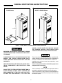
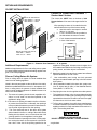
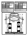
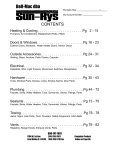
GENERAL SPECIFICATIONS AND INSTRUCTIONS
DLAS Series
DGAT & DGAM Series
24”
23”
19--1/2”
24”
19--1/2”
23”
9--3/4”
9--3/4”
10--5/8”
10--5/8”
60 1/2”
(on Sub--Base)
76”
1--- 7/8”
15--- 7/8”
2”
15--- 7/8”
Figure 1 -- DLAS, DGAT, and DGAM Series Furnace Dimensions
ABOVE 14 INCHES WATER COLUMN MAY DAMAGE
THE FURNACE CONTROL VALVE WHICH COULD
CAUSE AN EXPLOSION, FIRE, OR ASPHYXIATION.
IMPROPER INSTALLATION, ADJUSTMENT, SERVICE
OR MAINTENANCE CAN CAUSE INJURY OR PROPERTY DAMAGE.
These instructions are intended for the use of qualified individuals specially trained and experienced in installation of
this type of equipment and related system components.
PLEASE REFER TO ALL THE INSTRUCTIONS OF THIS
MANUAL FOR PROPER INSTALLATION PROCEDURES. IMPROPER INSTALLATION WILL VOID THE
WARRANTY.
Installation and service personnel are required by some
states to be licensed.
Persons not qualified shall not install this equipment or
interpret these instructions.
THE FURNACE SHALL BE INSTALLED SO THE ELECTRICAL COMPONENTS ARE PROTECTED FROM
WATER.
NOTE
The words “Shall” or “Must” indicate a requirement which is
essential to satisfactory and safe product performance.
The words “Should” or “May” indicate a recommendation or
advice which is not essential and not required but which may
be useful or helpful.
DO NOT TEST THE FUEL SYSTEM AT MORE THAN 14
INCHES WATER COLUMN AFTER FURNACE HAS
BEEN CONNECTED TO THE FUEL LINE. SUCH TESTING MAY VOID THE WARRANTY. ANY TEST RUN
5
FURNACE SPECIFICATIONS
TABLE 1 — Furnace Specifications
DGAM — Automatic ignition — with Built--in Coil Cabinet — 4 Ton -- A/C Ready
Model No.
Factory Equipped for use with:
Input/BTUH
Output/BTUH
DGAM056BDE
NATURAL GAS
56,000
46,000
DGAM075BDE
NATURAL GAS
75,000
61,000
DGAT — Automatic Ignition — with Built--in Coil Cabinet — 3 Ton -- A/C Ready
Model No.
Factory Equipped for use with:
Input/BTUH
Output/BTUH
DGAT056BDE
NATURAL GAS
56,000
46,000
DGAT070BDE
NATURAL GAS
70,000
57,000
DGAT075BDE
NATURAL GAS
75,000
61,000
DGAT090BDE
NATURAL GAS
90,000
72,000
Model No.
DLAS056BDE
DLAS075BDE
DLAS — Automatic Ignition — Heating Only — No Coil Cabinet
Factory Equipped for use with:
Input/BTUH
PROPANE
56,000
PROPANE
75,000
Output/BTUH
47,000
62,000
TABLE 2 — Electrical Specifications
Electrical Power Supply —
Breaker or Fuse —
Thermostat Circuit —
Nominal Anticipator Setting —
Gas Valve Inlet —
120 Volts — 60 Hz — 1 Phase
15 Amp
24 Volt — 60 Hz — 40 VA
.50
1/ ” NFPT
2
6
INSTALLATION STANDARDS
Comply with Local Codes
MINIMUM FURNACE CLEARANCES
The installer shall familiarize himself with and comply with all
local codes and regulations which govern the installation of
this appliance. Local codes and regulations shall take precedent over these regulations where applicable. In lieu of local
codes, the appliance shall be installed in accordance with:
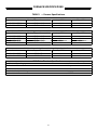
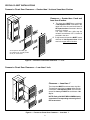
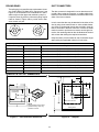
Access for servicing is an important factor in the location of
any furnace. A minimum of 24 inches should be provided in
front of the furnace for access to the heating elements and
controls. This access may be provided by a closet door or by
locating the furnace 24 inches from a facing wall or partition.
In the U.S.A.:
These furnaces are design certified for the following minimum clearances from combustible material in alcove or
closet installation:
the National Electrical Code, in accordance with recommendations made by the National Board of Fire Underwriters, in accordance with the the American National
Standard Institute National Fuel Gas Code (Ansi
Z223.1/NFPA--54).
TABLE 3 — Minimum Clearances
The installation must conform with:
local building codes,
Federal Manufactured Home Construction & Safety
Standard (H.U.D. Title 24, Part 3280),
or in the absence of local codes with:
American National Standard Mobile Homes A225.1 for
installation in mobile homes, and American National
Standard (ANSI--C1/NFPA--70) for all electrical wiring,
and American National Standard (A119.2/ NFPA--501C)
for installation in recreational vehicles.
CLOSET
ALCOVE
BACK
0”
0”
SIDES
0”
0”
FRONT
6”
24”
TOP
2”
2”
ROOF JACK
0”
0”
DUCT
0”
0”
ALCOVE
In Canada:
Manufactured (Mobile) Homes:
Unit installation shall comply with current CSA standard
CAN/CSA--Z240.4.1 -- Installation Requirement for Gas
Burning Appliances in Mobile Homes.
Unit electrical wiring and grounding shall comply with
current standard CSA C22.1 -- Canadian Electrical
Code Part 1.
Recreational Vehicles:
Unit installation shall comply with current CSA standard
CAN/CGA--Z240.4.2 -- Installation Requirements for
Propane Appliances and Equipment in Recreational Vehicles.
Unit electrical wiring and grounding shall comply with
current CSA standard C22.2 No.148/CAN/CSA-Z240.6.2 -- Electrical Requirements for recreational vehicles.
23--1/2”
20”
Minimum
Figure 2 — Alcove Installation
HIGH ALTITUDE INSTALLATION
For elevation above 2,000 feet, derate furnace orifice
4% for each 1,000 feet of elevation above sea level. Derating is accomplished by reducing the orifice size.
See Derating Chart for orifice size.
7
RETURN AIR REQUIREMENTS
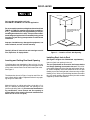
CLOSET INSTALLATIONS
Furnace to Closet Door Clearance —
Greater than 6 Inches
Return Air Grille Part No.
7900--286P/A — Almond
7900--287P/A — White
The closet door MUST have a minimum of 250
Square Inches of free area in the upper half of the
door.
If the opening for return air is located in the sidewall and below the top of the furnace casing:
a. total side return must equal or exceed
350 sq. in. free area
b. 6” min. clearance must be provided on
the side where the return is located
c.
6” min. clearance must be maintained
in front of the furnace.
CLOSET
FURNACE
6” or greater —
Closet to Door
Clearance
Return Air Closet Door Part No.
7900--8881 — Almond
7900--7771/C — White
DOOR
Figure 3 — Closet to Door Clearance — 6” or greater
Additional Requirements
appliance’s rating plate. At least one such register is to
be located where likelihood of its being covered by carpeting, boxes, and other objects is minimized.
Additional requirements for floor and ceiling return system
for closet installed sealed combustion heating appliance are
given in the next paragraph.
E. Materials located in the return duct system have a flame
spread classification of 200 or less.
Floor or Ceiling Return Air System
F.
Floor or ceiling return air system for closet installed direct
vent forced air heating appliance.
Non--combustible pans having one--inch upturned
flanges are located beneath openings in the floor return
duct system.
Listed in the next paragraph are the conditions to be met by
Mobile Home Manufacturers to have U.L. acceptance of in-floor or ceiling return air systems of closet installed direct
vent forced air heating appliances for Mobile Homes to be
sold in the United States.
G. Wiring materials located in the return duct system conform to Article 300--22 (b&c) of the National Electric
Code (ANSI C1 / NFPA--70).
A. The return--air opening into the closet, regardless of location, is to be sized not less than specified on the
appliance’s rating plate.
I.
H. Gas piping is not run in or through the return duct system.
B. If the return--air opening is located in the floor of the closet (versus the vertical front or side wall), the opening is
to be provided with means to prevent its inadvertent closure by a flat object placed over the opening.
C.
The negative pressure in the closet as determined by
test with the air--circulating fan operating at high heating
speed and the closet door closed is to be not more negative than minus 0.05--inch water column.
J. For floor return systems, the mobile home manufacturer
or installer shall affix a prominent marking on or near the
appliance where it is easily read when the closet door is
open. The marking shall read:
The cross--sectional area of the return duct system
(when located in the floor or ceiling of the mobile home)
leading into the closet is to be not less than that of the
opening specified on the appliance’s rating plate.
HAZARD OF ASPHYXIATION
DO NOT COVER OR RESTRICT FLOOR OPENING
D. The total free area of openings in the floor or ceiling registers serving the return--air duct system is to be not less
than 150% of the size of the opening specified on the
or equivalent.
8
SPECIAL CLOSET INSTALLATIONS
Furnace to Closet Door Clearance — Greater than 1 Inch and Less than 6 Inches
Clearance — Greater than 1 Inch and
Less than 6 Inches
A. The closet door MUST have a minimum
of 250 Square Inches of free area in the
upper half of the door and a minimum of
50 Square Inches of free area in the lower area of the door.
The lower closet door grille may be
omitted if an undercut of 2 1/2 Inches is
provided in the door.
B. A fully louvered closet door MUST have a
minimum of 250 Square Inches of free
area in the upper half of the door.
As an option to the lower grill,
an undercut of 2 1/2” will provide
50 Sq. In. of free area.
Figure 4 — Furnace to Closet Door Clearance — 1” to 6”
Furnace to Closet Door Clearance — Less than 1 Inch
Clearance — Less than 1”
The closet door MUST have three return air grilles.
The total free area of the two upper grilles must be
a minimum of 250 Square Inches. The total free
area of the lower grille MUST be a minimum of 50
Sq. In.
NOTE: Each grille MUST BE ALIGNED directly
opposite the corresponding return air grille of
the furnace door.
Figure 5 — Furnace to Closet Door Clearance — Less than 1”
9
AIR DISTRIBUTION SYSTEMS
Location, size and number of registers should be selected
on the basis of best air distribution and floor plan of the
home.
For proper air distribution, the supply duct system shall be
designed so that the static pressure does not exceed the
listed static pressure rating on the furnace rating plate.
The Air Temperature Rise is to be adjusted to obtain a temperature rise within the range(s) specified on the furnace
rating plate.
Three typical distribution systems are illustrated in Figure 6.
C
Transition Duct with Branches
A
Single trunk duct
Transition duct
B*
Dual trunk duct with crossover connector
Branches
1
Dual trunk duct
*B
Crossover
4
2
3
S
1
Crossover Duct must be centered directly under furnace.
S
2
Use 12” Diameter Round or equivalent insulated Flex--duct only.
S
3
Terminate Flex--duct (opposite furnace) in the center of the trunk duct.
S
4
Flex--duct material must be pulled tight — No Loops or unnecessary dips —
Air Flow may be impeded.
Figure 6 — Air Distribution Systems
10
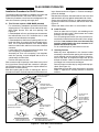
ROOF JACKS
Mark Center
Only use the appropriate roof jack.
See TABLE 4 & TABLE 5 for correct application.
9--3/4”
Do not exceed the maximum height as determined from
TABLE 4 & TABLE 5. Installer should allow an additional 1-- 1/2” travel before the flue pipe assembly is fully extended against the built--in stop. This provides an additional safeguard against the flue assembly being pulled
from the roof jack during transportation or other stress
conditions.
12--1/4”
These dimensions may be
used if furnace fits snug
against wall.
Improper installation may damage the equipment, can
create a hazard, and will void the warranty.
TEMPLATE FRONT
Carefully follow all instructions and warnings to avoid
Fire, Explosion, Or Asphyxiation.
Figure 7 — Location of Roof Jack Opening
Installing Roof Jack in Roof
Locating and Cutting Roof Jack Opening
(See Figure 8 & Figure 9 for Dimensional requirements.)
Insert roof jack into opening in the roof.
To facilitate the proper installation of the roof jack, it is very
important that the roof jack opening in the ceiling and roof be
on the same vertical center line as the furnace flue collar.
See Figure 7.
The roof jack should be secured to the furnace before
roof flange (flashing) is secured to the roof. This will insure a better alignment of the flue pipe and furnace flue collar. Caulk completely around the underside of the roof jack
flashing to provide a rain tight seal, before securing roof jack
flashing to roof. After roof jack flashing has been secured to
the roof, caulk carefully all around swivel joint with sealant
supplied by furnace manufacturer.
The dimensions shown in Figure 7 may be used if the furnace is flush with the walls or adjusted to allow for any spacing away from either wall.
Mark this location on ceiling and scribe a circle with a 5” radius (10” diameter) around this mark. Cut opening for roof
jack through ceiling and roof. (If furnace was installed during construction, cover furnace and flue opening to
prevent debris from entering flue and combustion air
when hole is cut for roof jack.)
11
TABLE 5 — DGAT & DGAM Roof Jacks
TABLE 4 — DLAS Roof Jacks
Roof Jack
Model
Number
4000--7121/C
4000--7141/C **
4000--7151/C **
4000--7171/C
Installation Dimensions
Installation Dimensions
Roof Jack
Model
Number
¡
Adjustable Height
75” to 86”
These dimensions are
from the floor to the
83” to 104”
top side of the roof.
roof
90” to 116”
(See Figure 8.)
127” to 157”
4000--7101/C
¡
Adjustable Height
86” to 95”
4000--7121/C
91” to 102”
4000--7141/C **
99” to 120”
4000--7151/C **
106” to 132”
4000--8161/C *+
85” to 101”
4000--7171/C
143” to 173”
4000--8181/C *+
99” to 129”
4000--8161/C *+
101” to 117”
* These jacks have removable crowns.
4000--8181/C *+
115” to 145”
Note: It is recommended that the 7900--6171 (17”) Interior
extension be used with these models. If used refer to
TABLE 5 for sizing of roof jack.
** Available with 3--1/2, 12 Pitch Fixed Flashing.
Models 4000--6141 and 4000--6151
+ Available with 3--1/2, 12 Pitch Fixed Flashing.
Models 4000--9161 and 4000--9181
* These jacks have removable crowns.
These dimensions
are from the floor to
the top side of the
roof. See Figure 9.
** Available with 3--1/2, 12 Pitch Fixed Flashing.
Models 4000--6141 and 4000--6151
+ Available with 3--1/2, 12 Pitch Fixed Flashing.
Models 4000--9161 and 4000--9181
NOTE: ROOF FLANGE IS ADJUSTABLE UP TO 23” (5-- 12 PITCH)
CAULK CAREFULLY ALL AROUND
SWIVEL JOINT WITH SEALANT
SUPPLIED BY FURNACE
MANUFACTURER.
FLUE
GASES
19 1/2”
FLUE
GASES
19 1/2”
COMBUSTION
AIR
COMBUSTION
AIR
CAULK
UNDER
FLASHING
CAULK
UNDER
FLASHING
The Bead or End of Upper Portion
of Roof Jack need Not extend
below the ceiling.
ROOF
IMPORTANT
SEAL ROOF JACK FLASHING TO THE ROOF
JACK AND ROOF.
THIS IS THE INSTALLER’S RESPONSIBILITY.
76”
60--1/2”
(INCLUDES
SUB--BASE)
FLOOR
WARM AIR DUCT
DUCT CONNECTOR
DUCT CONNECTOR
Figure 8 — DLAS Models
WARM AIR DUCT
Figure 9 — DGAT & DGAM Models
12
CEILING RINGS
DUCT CONNECTORS
The ceiling ring is to meet fire stop requirements. Accessory Ceiling Ring (P/N 7660--2841) may be used, (see
Figure 10) or the mobile home manufacturer or the installer may use other approved methods to stop fire.
If required, three (3) sections of Accessory Ring may be
used as shown in Figure 10B to provide closer clearance around roof jack.
A
The duct connector is designed for use on ducts down to 12”
in width. When using the connector on smaller width ducts,
there will not be sufficient clearance to bend the tabs on two
sides of the duct connector.
In such cases the tabs may be attached to the sides of the
duct by using sheet metal screws or other suitable fasteners. Holes for sheet metal screws are provided in three (3)
tabs on each side of the duct connector. If more than 3 tabs
need to be used to provide a more secure and air tight connection, the remaining tabs can also be fastened to the duct
with screws after drilling the required screw holes.
B
If tape is used to provide a better air seal, it should be a type
approved by the applicable national or local codes.
Figure 10 — Ceiling Rings
TABLE 6 — Duct Connectors
Sales Package
Part Number
Depth
7681--6621
7681--602
2” Duct Connector — For Ducts 1--1/8” below top of floor surface
7681--6631
7681--603
3” Duct Connector — For Ducts 2--1/8” below top of floor surface
7681--6651
7681--605
5” Duct Connector — For Ducts 4--1/8” below top of floor surface
7681--6661
7681--606
6” Duct Connector — For Ducts 5--1/8” below top of floor surface
7681--6671
7681--607
7” Duct Connector — For Ducts 6--1/8” below top of floor surface
7681--6681
7681--608
8” Duct Connector — For Ducts 7--1/8” below top of floor surface
7681--6691
7681--609
9” Duct Connector — For Ducts 8--1/8” below top of floor surface
7681--6611
7681--611
11” Duct Connector — For Ducts 10--1/8” below top of floor surface
7681--6711
7681--612
12” Duct Connector — For Ducts 11--1/8” below top of floor surface
TEMPLATE & CUTOUT DIMENSIONS
1--13/16
15--7/8”
1--15/16”
9--3/4”
14”
Duct Cutout
Dimensions
11--9/16”
15--7/8”
12”
9--7/8”
12--1/4”
Duct
Locating
Hole
23”
13--9/16”
Flue Center
Floor Cut--out Line
NOTE:
Duct Connector may be used
positioned in any of four (4))
positions to fit duct.
Casing Front
Door Front
1”
Figure 12 — Template
Figure 11 — Duct Connector Dimensions
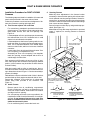
13
DLAS SERIES FURNACES
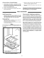
Installation Procedure for DLAS Furnace
ing to dimensions shown in Figure 11. Cut duct accurately to
prevent air leakage.
Reinstall duct connector with tabs inside of hole in the duct
and bend tabs up firmly against underneath side of duct.
Secure duct connector with four (4) sheet metal screws using holes provided in the connector, and the sub--base. See
Figure 13.
Secure sub--base to floor with 2 or more screws or nails.
The following steps are listed for installation of furnace and
need not be performed in the exact order as listed.
Follow this procedure to avoid serious misalignment of furnace duct connector opening and supply duct.
A. This Furnace requires a SUB--BASE (Included)
For convenience, a template is provided on the furnace
shipping carton. This may be cut out and used to accurately locate furnace, floor and vent openings. See
Figure 12.
Locate template on floor to provide proper clearances to
the walls and the front. Cut 2” diameter hole or small
square hole as indicated on template.
Locate template so that furnace opening outline is centered over under--floor supply duct as accurately as possible. This is important because of the limited adjustment from side to side, and from front to rear of the duct
connector.
Locate under--floor duct through hole and center “floor
cut--out opening” on template over duct.
Accurately cut “floor cut--out opening” from template,
mark floor opening, remove template and cut floor on
outside edge of marked line.
Position sub--base over hole.
B. Install Furnace
Check to make sure roof jack is not extending too far
down into furnace location. Slide furnace into location
and align over floor opening.
Pre--cut openings and knock--outs are provided in furnace base to install a front fuel line and/or front refrigerant lines. If rear entrance lines are to be used, they
must be installed before the duct connector is installed and secured in place.
For air conditioning lines, remove the knock--out.
C. Securing Furnace
Make any minor adjustments in the furnace location
necessary to insure that the opening in the furnace bottom is centered over the opening in the duct. Secure furnace to sub--base, as required, through holes at front
and rear of furnace. Holes for screws are located in bottom flange front corners and rear flanges.
Secure furnace to wall at top by using metal strap provided. (See Figure 13.)
Manufacturers may add straps equivalent to provided
straps, if required, for securing furnace to structural
member.
Duct connectors will fit openings of sub--base in any one of
four (4) positions. Place proper duct connector in the opening in the best position, (duct connector may be shifted in either direction for best location).
Mark duct opening with a scribe or marking pen, then remove duct connector. Cut hole in duct to correct size accordSecure duct connector
to sub--base with 4
screws.
Bend tabs of duct
connector under duct
opening to secure to the
supply duct.
Secure Sub--base to
floor firmly with 2 or
more screws Or
nails.
For improved air
seal, duct
connector flanges
may be sealed to
the sub--base with
aluminum duct
tape.
Secure sub--base to
floor with 2 nails or
screws.
Use screw holes in sub--base
to fasten duct connector .
1..
TABS
TABS
DUCT
DUCT
Insert Duct Plenum Connector Into Duct Cut--out.
2..
Bend Bottom Tabs Over And Onto
The Underneath Duct Service.
Figure 13 — Sub--base / Duct Connector
14
DGAT & DGAM SERIES FURNACES
Installation Procedure for DGAT & DGAM
Furnaces
C. Securing Furnace
Make any minor adjustments in the furnace location
necessary to insure that the opening in the furnace bottom is centered over the opening in the duct. Secure furnace to floor, as required, through holes at front and rear
of furnace. Holes for screws are located in bottom flange
front corners and rear flanges.
Secure furnace to wall at top by using metal strap provided. (See Figure 14.)
Manufacturers may add straps equivalent to provided
straps, if required, for securing furnace to structural
member.
The following steps are listed for installation of furnace and
need not be performed in the exact order as listed:
Follow this procedure to avoid serious misalignment of furnace duct connector opening and supply duct.
A. This Furnace requires NO sub--base
For convenience, a template is provided on the furnace
shipping carton. This may be cut out and used to accurately locate furnace, floor and vent openings. See
Figure 12.
Locate template on floor to provide proper clearances to
the walls and the front. Cut 2” diameter hole or small
square hole as indicated on template.
Locate template so that furnace opening outline is centered over under--floor supply duct as accurately as possible. This is important because of the limited adjustment from side to side, and from front to rear of the duct
connector.
Locate under--floor duct through hole and center “floor
cut--out opening” on template over duct.
Accurately cut “floor cut--out opening” from template,
mark floor opening, remove template and cut floor on
outside edge of marked line.
Secure furnace to duct
connector base with 4
screws.
Bend tabs of
duct connector
under duct
opening to secure to the supply duct.
Duct connectors will fit opening in any one of four (4) positions. Place proper duct connector in the opening in the best
position, (duct connector may be shifted in either direction
for best location).
Mark duct opening with a scribe or marking pen, then remove duct connector. Cut hole in duct to correct size according to dimensions shown in Figure 11. Cut duct accurately to
prevent air leakage.
Reinstall duct connector with tabs inside of hole in the duct
and bend tabs up firmly against underneath side of duct.
Secure duct connector to floor with four (4) sheet metal
screws using holes provided in the connector. See
Figure 14.
SUPPLY DUCT
OPENING
Furnace
Base
Use screw holes in furnace
base to fasten to duct connector (relative to position of duct Refrigerant
connector) .
Line Opening
B. Install Furnace
Remove panel from air conditioning compartment.
Check to make sure roof jack is not extending too far
down into furnace location. Slide furnace into location
and align over floor opening.
Pre--cut openings and knock--outs are provided in furnace base to install a front fuel line and/or front refrigerant lines. If rear entrance lines are to be used, they
must be installed before the duct connector is installed and secured in place.
For air conditioning lines, remove the knock--out.
1.
Fuel Line
Opening
TABS
TABS
DUCT
DUCT
Insert Duct Plenum
Connector Into Duct
Cut--out.
2.
Bend Bottom Tabs Over
And Onto The Underneath
Duct Service.
Figure 14 — Duct Connector
15
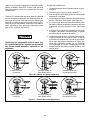
CONNECTING ROOF JACK TO FURNACE
It is mandatory that the combustion air and flue tube
assembly be fully engaged at back sides and front,
and combustion air tube securely fastened to the furnace with sheet metal screws (2) in the screw holes
provided.
The inner flue pipe must be present.
It is mandatory that the combustion air pipe and flue
pipe assembly be fully engaged. The combustion air
pipe MUST be securely fastened to the furnace with
sheet metal screws in the holes provided.
COMBUSTION
AIR TUBE
SECURE
STRAP
TO WALL
Use 1/2” blunt or sharp end sheet metal screws to fasten
roof jack combustion air pipe to furnace combustion air
collar. Screw holes are provided in the pipe and collar.
Excessively long screws may extend to flue pipe and
puncture it. Screws are not to exceed 1 1/2” in length.
FLUE
PIPE
FURNACE
FLUE OUTLET
NOTE
Combustion air tube and flue pipe are part of the same assembly. Only the combustion air tube need be fastened to
the furnace.
GASKET
SCREW
HOLES (2)
COMBUSTION
AIR TUBE COLLAR
FRONT OF FURNACE
1. Check to be certain that the flue pipe and combustion air
tube are present.
#8 OR #10
SCREWS RECOMMENDED
2. Pull the telescoping flue tube and combustion air tube
assembly down from the roof jack. Slide the flue tube/
combustion air tube assembly down firmly over the furnace flue outlet and combustion air collar. Insure that
the back, side and front of combustion air tube collar is
fully engaged and is in contact with gasket. Fasten the
combustion air tube to the furnace combustion air collar
using two (2) 1/2 inch sheet metal screws. (Screw holes
are provided in combustion air tube and furnace combustion air collar. (See Figure 15.)
Figure 15 — Connecting Roof Jack to Furnace
16
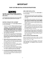
IMPORTANT
VENT SYSTEM INSTALLATION INSTRUCTIONS
NEW HOME INSTALLATION
IF THIS FURNACE IS INSTALLED ON A NEW HOME DO
THE FOLLOWING
FAILURE TO FOLLOW ALL VENTING INSTRUCT-IONS CAN RESULT IN FIRE, ASPHYXIATION, OR
EXPLOSION.
1. Inspect the furnace top collars for signs of insulation or
ceiling debris which might have fallen in during cutting
of the ceiling and roof holes. Remove all debris before
continuing.
The vent system is an important part of your furnace installation. Carefully read and observe the following basic instructions, as well as those packed with the vent system.
2. After unpacking the vent system, check the rain caps.
Insure they are not damaged, tilted or crooked. Do not
twist, crush or sit on the roof caps during installation. Damaged roof caps will cause improper furnace
operation. The furnace will not heat properly and could
result in explosion.
EXISTING FURNACE REPLACEMENT
IF THIS FURNACE REPLACES AN EXISTING FURNACE,
DO THE FOLLOWING.
3. Before inserting the vent pipe into the furnace top, inspect the furnace flue and combustion air opening for
debris or insulation which might have fallen in during
pre--installation steps. Do not proceed unless all debris
have been cleaned out or removed.
2nd
1. If a
roof, roof cap or addition has been made to the
existing roof of the home, remove the old vent system
completely!... to avoid the possibility of an improperly installed pipe or gaps in the old vent system,
INSTALL A NEW VENT SYSTEM. Your ceiling and
roof height will determine the correct vent system
to use. Refer to the vent selection table, of the furnace installation instructions.
4. After installing vent pipe on furnace top collar, check to
make sure there is no gap in back or side between the
pipe collar and the furnace casing top. If necessary to
prevent excessive air leakage, the installer should seal
joints in the combustion air tube with aluminum type or
other suitable sealant.
2. After unpacking the vent system, check the rain caps.
Insure they are not damaged, tilted or crooked. Do not
twist, crush or sit on the roof caps during installation. Damaged roof caps will cause improper furnace
operation. The furnace will not heat properly and could
result in explosion.
INSTALLATION IN SNOW REGIONS
When the combustion air pipe inlet is covered or blocked
with snow, the furnace will not operate properly due to the
depleted combustion air supply.
3. Before inserting the vent pipe into the furnace top, inspect the furnace flue and combustion air opening for
debris or insulation which might have fallen in during
pre--installation steps. Do not proceed unless all debris
have been cleaned out or removed.
Therefore, if the furnace will be located in regions where
snow accumulation on the roof exceeds 7” or in H.U.D.
Snow Load Zones, a # 7680B6541 roof jack extension is
recommended.
4. After installing vent pipe on furnace top collar, check to
make sure there is no gap in back or side between the
pipe collar and the furnace casing top.
5. Use only the pipes provided with the roof jack assembly.
Do not add to or adapt other sheet metal pipes. Do not
cut, insert or add other pipes to this assembly.
6. In no case should there be a gap between sections of
the flue pipe or the combustion air pipe. If necessary to
prevent excessive air leakage, the installer should seal
joints in the combustion air tube with aluminum type or
other suitable sealant.
17
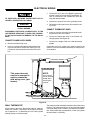
ELECTRICAL WIRING
c.
TO INSTALLER: INCOMING POWER MUST BE POLARIZED. OBSERVE COLOR CODING.
d. Connect the “ground” wire to the grounding screw.
DANGER
e. Reinstall the control panel cover and secure mounting screw.
-- SHOCK HAZARD --
CONNECT THERMOSTAT WIRES
DISCONNECT ELECTRICAL POWER SUPPLY TO THE
UNIT BEFORE SERVICING TO AVOID THE POSSIBILITY OF SHOCK INJURY OR DAMAGE TO THE EQUIPMENT.
a. Insert 24 volt wires through the small plastic bushing just above the control panel.
b. Connect the thermostat wires to the furnace low
voltage pigtails (See Figure16).
CONNECT POWER SUPPLY WIRES
c.
a. Remove the field wiring cover.
b. Insert 115 volt wires through the large plastic bushing on the left side of the furnace ( See Figure 16).
If conduit is used it should be secured to the control
box.
This screw does not
need to be removed in
order to remove the
field wiring cover. (just
loosen).
Connect the “hot” wire to the BLACK pigtail lead,
and the “neutral” wire to the WHITE pigtail lead. Secure all connections with suitable wire nuts and
wrap with electrical tape.
Connect low--voltage circuit to the wall thermostat
pigtails.
A separate 120 V.A.C. supply circuit must be used for the
furnace. The circuit should be protected by a 15 amp fuse or
circuit breaker.
NOTE:
Cover should
not be removed
except when
servicing the
controls.
Figure 16
WALL THERMOSTAT
The wall thermostat should be located 52 to 66 inches above
the floor. The preferred location is on an inside wall situated
in an area with good air circulation, and where the temperature will be reasonably representative of other living areas
the thermostat is controlling.
Avoid locations where the thermostat could be subject to
drafts from outside, or exposed to direct light from lamps,
sun, fireplaces, etc., or affected by air from a duct register
blowing directly on the thermostat.
18
THERMOSTAT WIRING FOR DGAT AND DGAM SERIES
White
Green
Red
Black
Blend Air
Control Box
White
White
Green
Green
Red
Red
Black
Yellow
Yellow
Condensing
Unit
Wall Thermostat
Furnace Control Box
Not Factory Installed
Figure17 -- Thermostat Wiring
19
THERMOSTAT WIRING FOR DLAS (HEAT ONLY) SERIES
White
Green
White
W
Black
Red
Red
Yellow
R
Wall Thermostat
(Rear View)
Furnace Control Box
Figure17a - Thermostat Wiring for DLAS Series
20
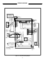
WIRING DIAGRAMS
GRN
Upper
Limit Switch
WHT
GRY
WHT
W
BLK
BLU
Y
Wall
Thermostat
Centrifugal
Switch
BRN
XFMR
L1
HEAT
WHT
WHT
COM
RED
24
VAC
Transformer
Ground
Screw
System
Switch
Neutral
L1
Combustion
Blower
Motor
WHT
BLU
LINE
RED
WHT
BLK
WHT
BLK
BLK
BLK
Incoming Power Must
Be Polarized. Observe
Color Coding
Gas
Valve
2
1
Hot Surface
Ignitor
Figure 18 -- DGAT Series Wiring Diagram
21
Sensor Rod
To Earth Ground
BRN
BLK
6
5
4
3
2
1
BLK
Blower
Motor
9
8
7
6
5
4
3
2
1
NEUTRALS
BLK
COOL
BRN
To A/C
Condensing
Unit (If
equipped)
{
YEL
BLU
R
YEL
115
VAC
GRN
1 2 3 4 5 6 7 8 9
G
C
RED
RH
Y
ORG
W
GRN
G
Lower
Limit
Switch
BLU
LOAD
BLK
RED
Blend Air
Control Box
(If equipped)
WIRING DIAGRAMS
Upper
Limit
Switch
WHT
GRN
GRY
WHT
W
G
BLK
BLU
Y
Wall
Thermostat
BRN
BLK
6
5
BLK
L1
COOL
BLK
LINE
WHT
WHT
24
VAC
Transformer
Ground
Screw
Gas
Valve
System
Switch
Neutral
L1
COM
RED
2
BLK
Incoming Power Must
Be Polarized. Observe
Color Coding
1
Hot Surface
Ignitor
Figure 19 -- DGAM Series Wiring Diagram
22
Sensor Rod
To Earth Ground
Combustion
Blower
Motor
WHT
BLU
LOAD
1
2
1
BLK
RED
WHT
3
BLK
7
6
5
4
3
2
WHT
RED
9
8
NEUTRALS
BLK
HEAT
4
WHT
{
Centrifugal
Switch
BRN
To A/C
Condensing
Unit (If
equipped)
115
VAC
YEL
BLU
R
YEL
Blower
Motor
GRN
1 2 3 4 5 6 7 8 9
C
RED
Y
ORG
W
G
GRN
RH
Lower
Limit
Switch
BLU
XFMR
BLK
RED
Blend Air
Control Box
(If equipped)
GAS PIPING
INSTALLATION AND CHECKING OF GAS LINE
When converting valve from or to Propane gas, it will be necessary to change main burner orifice to prevent an underfired or overfired condition. See furnace nameplate for complete instructions.
Gas Supply piping must be sized in accordance with the recommendations contained in “American National Standard
Institute Installation of Gas Piping” ANSI 223.1 unless local
codes or regulations state otherwise.
Materials used and pipe sizing for U.S. mobile homes must
comply with requirements contained in Mobile Homes
A119.1, Recreational Vehicles A119.2 and H.U.D. Title 24,
Section 280.705 and any local or state codes.
If the gas input to the furnace is too great because
of excessive gas pressure, wrong size orifice,
high altitude, etc., the burner flame will be sooty
and may produce carbon monoxide, which could
result in unsafe operation, explosion, and/or fire
or asphyxiation.
NOTE
The gas line inlet on the gas valve is 1/2 --14 N.P.T. The gas
line may be installed through the furnace floor or furnace
side to the gas valve.
Observing Burner Operation
1. Observe burner to make sure it ignites. Observe color
of flame. On natural gas the flame will burn blue with appreciably yellow tips. On Propane gas a yellow flame
may be expected. If flame is not the proper color call a
qualified serviceman for service.
To install gas line and to connect it to the gas valve, care
must be taken to hold gas valve firmly to prevent misalignment of the burner orifice, or to damage gas valve
which could result in improper heating, explosion, fire
or asphyxiation.
2. Let furnace heat until blower cycles on.
DO NOT USE EXCESSIVE PIPE SEALANT ON PIPE
JOINTS. Pipe sealant, metal chips or other foreign material that could be deposited in the inlet of the gas
valve, when gas pipe is installed or carried through the
gas piping into the gas valve inlet after installation, may
cause the gas valve to malfunction and could result in
possible improper heating, explosion, fire or asphyxiation. Also, pipe sealant must be resistant to Propane
gas.
3. Turn thermostat down.
4. Observe burner to make sure it shuts off.
5. Let the furnace cool and blower cycle off.
Should overheating occur, or the gas supply fail to
shut off, shut off the manual gas valve to the furnace and allow burner to run until furnace cools
down and blower shuts off before shutting off the
electrical supply.
Where regulations require, a main shut--off valve shall
be installed externally of furnace casing. After piping
has been installed, turn gas on and check all connections with a leak detector or soap solution.
NEVER USE OPEN FLAME. FIRE OR EXPLOSION
COULD OCCUR.
Do not test the fuel system at more than 14” W.C. after
furnace has been connected to fuel line. Such testing
could void the warranty. Any test run above 14” W.C.
may damage furnace control valve which could cause
an explosion, fire or asphyxiation.
If any abnormalities are observed when checking for correct
operation, such as burner failing to ignite or to turn off, sooty
flame, etc., call your nearest authorized service technician
as shown in the Service Center List included in the home
owner envelope with the furnace.
Combustion Air
A dirt leg may be required by some local codes to trap moisture and contaminations.
In order for the burner flame to burn efficiently, it must receive adequate combustion air.
For NAT. gas operation, the furnace is designed for 7” W.C.
inlet gas pressure. Pressure to main burner is then reduced
to 3 1/2” W.C.
The amount of combustion air can be changed by operating
the combustion air adjustment rod located beneath the gas
valve. (See Figures 19 and 20.)
For Propane gas operation, the furnace is designed for 11”
W.C. inlet gas pressure. Pressure to main burner is then
reduced to 10” W.C.
The adjustment rod is set at an “average” position at the factory and may be properly set for many applications.
23
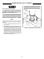
To adjust the combustion air:
However, the amount of combustion air required will vary depending on altitude, actual BTU. content of the gas being
used, gas pressure, conversion to another gas, and other
variable factors.
1. To light and operate furnace see label inside lower furnace door.
2. Allow the burner to burn for about 1 MINUTE.
3. Look through the observation window and observe the
appearance of the flame.
Therefore, it is essential that the burner flame be observed
and any necessary adjustments are made before the furnace is put into service at the final home site. Adjusting the
burner air is considered part of the normal home set--up procedure and is the responsibility of either the home seller or
buyer, depending on their agreement. Adjustments of this
type are not covered by the warranty.
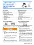
4. On natural gas, the base of the flame should be blue but
the tips of the flame will be yellow. (See Figure 20.)
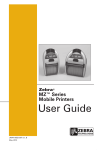
5. On Propane gas, almost all of the flame will be yellow
although some blue should still be present at the base
of the flame next to the end of the burner. (See Figure
21.)
6. If the flame is too yellow, the combustion air should be
increased. If the flame is excessively blue (no yellow)
the combustion air should be decreased.
7. To adjust the combustion air, loosen the lock screw holding the combustion air rod in place. Push in on the rod
to increase the combustion air. Pull out on the combustion air rod to decrease the combustion air. Tighten lock
screw after adjustment is made. Do not completely
close air damper at any time. Complete closure of air
damper to burner will result in improper operation. See
caution above.
Combustion air adjustments must be made only
by a qualified technician. Improper air adjustment
may cause unsafe operation, explosion or asphyxiation.
View of Burner Through the Observation Window
Correct Amount of
Primary Air
Too Little Primary Air
Push Shutter Rod In
Too Much Primary Air
Pull Shutter Rod Out
Figure 20 -- Natural Gas Flame Appearance
Correct Amount of
Primary Air
Too Little Primary Air
Push Shutter Rod In
Figure 21 -- Propane Gas Flame Appearance
24
Too Much Primary Air
Pull Shutter Rod Out
If Furnace Fails to Operate Properly
4. Make sure filters are clean, return grilles are not obstructed, and supply registers are open.
1. Check setting of thermostat -- and position of HEAT/
COOL switch if air conditioning is installed. If a set--back
type thermostat is employed be sure that the thermostat
is in the correct operating mode.
2. Check to see that electrical power is ON.
3. Check to see that the knob on the gas control valve is
in the full ON position.
5. Be sure that furnace flue piping is open and unobstructed.
If the cause for the failure to operate is not obvious, do
not attempt to service the furnace yourself. Call a qualified service agency or your gas supplier.
FINAL PROCEDURE
Install Furnace Doors
Furnace and Air Conditioner Installations
Install the bottom door first by holding the door flush
against the casing and sliding the door down until the
door top and bottom flanges rest in the casing channels.
Then install the upper door in the same manner.
In an air conditioner is installed which does not use the
blower for air distribution and operates completely independent of the furnace, the thermostat system must have an
interlock to prevent the furnace and air conditioner form
operating at the same time. This interlock system usually
contains a heat--cool switch which must be turned to either
HEAT or COOL to activate either heating or cooling operation, or a positive OFF switch on the cooling thermostat.
Finish and Trim
Alcove and Closet Installations may now be finished and trimmed as necessary.
Leave enough gap above upper furnace door to allow it
to be lifted and removed.
When used in connection with a cooling unit the furnace
shall be installed parallel with or on the upstream side of the
cooling unit to avoid condensation in the heat exchanger.
NOTE
See nameplate for conversion and lighting instructions. Obtain a temperature rise within the ranges specified on the
name plate.
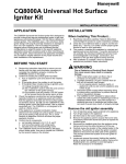
For installations with a parallel flow arrangement, the furnace must be equipped with a damper to prevent cold air
from being discharged up around the heat exchanger. Cold
air causes condensation inside the exchanger and can
cause it to rust out which can allow products of combustion
to be circulated into the living area by the furnace blower
resulting in possible asphyxiation. An air flow activated
automatic damper, P/N 7900--6771, is available from furnace manufacturer.
Automatic
Damper
SUPPLY DUCT
OPENING
Furnace
Base
Duct Connector
Note: For best air delivery install damper with blades
parallel to supply duct.
Figure 22 -- Anti--Backflow Damper
25
26
29
29
30
30
30
30
31
31
31
32
0.136
0.136
0.128
0.128
0.128
0.128
0.12
0.12
0.12
0.116
Sea Level
2,000
3,000
4,000
5,000
6,000
7,000
8,000
9,000
10,000
45
46
47
47
47
48
48
49
49
50
0.082
0.081
0.078
0.078
0.078
0.076
0.076
0.073
0.073
0.073
Sea Level
2,000
3,000
4,000
5,000
6,000
7,000
8,000
9,000
10,000
9951--0731
9951--0731
9951--0731
9951--0761
9951--0761
9951--0781
9951--0781
9951--0781
9951--0821
9951--0821
Part #
9951--1161
9951--1201
9951--1201
9951--1201
9951--1281
9951--1281
9951--1281
9951--1281
9951--1361
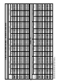
Adjust air shutter for correct flame appearance.
Table shows 4% Input Reduction per 1,000 feet Elevation.
Reference Source: NFPA No. 54, ANSI Z 223.1 1996 Edition.
Drill Size
Orifice
Dia.
Elevation
Part #
9951--1361
56,000 — Input
Drill Size
Orifice
Dia.
Elevation
56,000 — Input
0.078
0.081
0.082
0.086
0.086
0.089
0.089
0.089
0.093
0.093
Orifice
Dia.
0.128
0.136
0.136
0.14
0.144
0.144
0.147
0.149
0.149
0.154
Orifice
Dia.
47
46
45
44
44
43
43
43
42
42
Drill Size
Part #
9951--0781
9951--0811
9951--0821
9951--0861
9951--0861
9951--0891
9951--0891
9951--0891
9951--0931
9951--0931
Part #
PROPANE GAS
9951--1281
9951--1361
9951--1361
9951--1401
9951--1441
9951--1441
9951--1471
9951--1491
9951--1491
9951--1541
70,000 — Input
30
29
29
28
27
27
26
25
25
23
Drill Size
70,000 — Input
NATURAL GAS
0.082
0.086
0.086
0.089
0.089
0.093
0.093
0.093
0.096
0.098
Orifice
Dia.
0.136
0.14
0.144
0.147
0.149
0.152
0.154
0.157
0.157
0.161
Orifice
Dia.
45
44
44
43
43
42
42
42
41
40
Drill Size
Part #
9951--0821
9951--0861
9951--0861
9951--0891
9951--0891
9951--0931
9951--0931
9951--0931
9951--0961
9951--0981
Part #
9951--1361
9951--1401
9951--1441
9951--1471
9951--1491
9951--1521
9951--1541
9951--1571
9951--1571
9951--1611
75,000 — Input
29
28
27
26
25
24
23
22
22
20
Drill Size
75,000 — Input
HIGH ALTITUDE DERATION CHART — DGAM, DGAT, DLAS Series
0.089
0.093
0.096
0.096
0.098
0.099
0.101
0.101
0.104
0.106
Orifice
Dia.
0.152
0.157
0.161
0.161
0.166
0.169
0.173
0.173
0.177
0.18
Orifice
Dia.
43
42
41
41
40
39
38
38
37
36
Drill Size
Part #
9951--0891
9951--0931
9951--0961
9951--0961
9951--0981
9951--0991
9951--1011
9951--1011
9951--1041
9951--1061
Part #
9951--1521
9951--1571
9951--1611
9951--1611
9951--1661
9951--1691
9951--1731
9951--1731
9951--1771
9951--1801
90,000 — Input
24
22
20
20
19
18
17
17
16
15
Drill Size
90,000 — Input
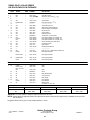
DGAM, DGAT & DLAS SERIES
HSI Gas Downflow Furnace
Repair Parts List for:
DGAM056BDE DGAT056BDE DLAS056BDE DGAT070BDE DGAM075BDE DGAT075BDE DLAS075BDE DGAT090BDE
31
13
14
35
34
33
30
29
2
15
16
24
32
27
26
3
21
14
22
23
4
28
6
5
18
BURNER ORIFICE
(SEE CHART)
10
Vestibule
8
7
11
19
17
*
*
B
CODE
USED ON
MODEL
NO.
PART
REQ. NUMBER
DESCRIPTION
__
2
3
4
5
ALL
---ALL
ALL
ALL
X
-1
1
1
Enamel (Spray 15 oz. White)
-----------------------Limit Switch (Upper)
Booster Assembly (Includes Motor)
Booster Motor -- 3000 RPM
8B247P
-----------7990--3591 B
7990--6451
7990--317P
NOTE: The 7624A3591 (180 Manual Reset) is a designed approved alternate for this limit switch.
27
20
DGAM, DGAT, & DLAS SERIES
HSI GAS DOWN FLOW FURNACE
CODE
*
*
*
*
*
*
*
*
6
7
8
9
10
11
12
13
14
15
16
17
18
19
20
21
22
23
24
25
26
27
28
USED ON
MODEL
NO.
PART
REQ. NUMBER
ALL
ALL
ALL
---ALL
DGAM,DGAT
---ALL
ALL
ALL
ALL
ALL
ALL
ALL
056
070,075
090
ALL
ALL
ALL
ALL
---ALL
DGAM
1
1
1
-1
1
-1
1
1
1
1
1
1
1
DLAS, DGAT
DESCRIPTION
7990--401
7990--319P
7990--328PBB
-------------7945--5151/C
7956A5201
-------------7990--368P
7945--3011
7995--5751
7975--3881
7681--3301
7990--402
2940A3541
7945--3281/A
7970--3281/A
7995--3281/A
7970--5851/A
1474--0521
7970--179
7945--1631/A
-----------1214--2511
7975--1561/B
Cover (Control Box)
Integrated Control
Gas Valve (24V .5 Amp 1/2” x 3/8”)
-------------------------Valve Bracket
Panel (Coil Cavity 19 13/16”)
-------------------------------Thermostat (Adj. Ant.)
Gasket Pkg. (Heat Exchanger)
Heat Exchanger (with Gaskets)
Remote Sensor
System Switch
Field Wiring Cover
Transformer (115--24V 40VA)
Limit Switch (OPEN--140º CLOSE--110º)
Limit Switch (OPEN--145º CLOSE--115º
Limit Switch (OPEN--150_ CLOSE--120_)
Burner Assembly (Less Gas Valve)
Hot Surface Ignitor
Ignitor Shield
Mounting Plate (Burner)
-------------------------Filter (16 x 20 x 1 Disposable) (2 Required)
Panel (Upper)(White)
7990--1561/A
Panel (Upper)(White)
DGAM,DGAT
1
1
1
7956--1571/A
Panel (Lower)(White)
DLAS
1
7956--1631/A
Panel (Lower)(White)
1
1
1
1
-1
1
BLOWER PARTS
*
*
29
DGAM
DGAT, DLAS
(057, 070, 075)
090
1
1
1468--220P
7966--311P
Motor
Motor
1
1468--212P
Motor
30
All
1
7966A530
Scroll
31
All
1
2702--4091
Motor Mount(3/Pkg.)
32
All
1
7680--348
Connector Plug
33
All
1
7670--6391
Motor Clamp
34
090
DGAM
All
1
1
1
1499--4461
1499--4471
1472--2751
Run Capacitor
Run Capacitor
Blower Wheel
(10 5/8 Dia. x 7 1/8 x 1/2)
35
MODEL
Nat.
LP
056
9951--1361
9951--0821
BURNER ORIFICE CHART
070
9951--1541
9951--0931
075
9951--1611
9951--0981
090
9951--1801
9951--1061
NOTE: The 7990--326P is a designed approved alternate for this valve.
NOTE: All parts with three digit suffix numbers are “Special Order” Parts. These parts are subject to factory availability and require extra
BB
time for delivery.
* Suggested Parts Inventory (2% of Units Installed--Minimum 1 each)
1973--106/E Rev. 1 (4/98) P.I.
UPG
Unitary Products Group
3110 North Mead
Wichita, KS 67219--- 4057
28
IGM0035X