1
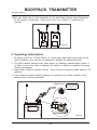
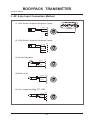
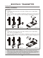
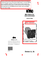
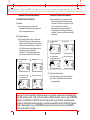
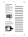
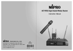
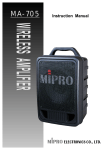
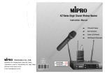
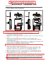
Follow the "pairing up" instructions in the
MRM70 Receiver manual included below.
BODYPACK TRANSMITTER
Operating Manual
1. Parts Names And Functions
ACT-707TE
ACT-3T
1
9
2
10
1
9
2
3
3
4
4
5
6
7
8
10
5
6
7
8
This bodypack transmitter is shown with the battery door open.
(Fig. 1)
(Actually it is shown with the battery door removed.)
1. AF Input Jack: Connects to a lavaliere or headset microphone. (See 5 ways of
connection on AF Input Connections)
2. Power Switch: Switch to ON position for operation. Switch to OFF position when not
in use.
3. Battery Status Indicator: Indicates the power on / off and battery status.
(a) When power switch is turned on: The LED indicator flashes briefly, indicating
normal battery status.
(b) When RED light illuminates at either power on or during usage: The battery level
is low, therefore, a new battery replacement is thus necessary.
4. Transmitter Housing: Packages the PCB and battery.
5. ACT Signal Receptor: Receiving ACT signal and adjusting frequency automatically.
6. Gain Control: Adjusts the desirous input gain.
7. GT/MT Level Selector: Switch GT position for electric guitar usage ONLY. Gain
Control is irrelevant for "GT". Switch to "MT" for condenser microphone, wired
microphone. Gain Control works in "MT" for input sensitivity adjusting.
8. Battery Compartment and Cover: Accommodates one 9 Volt battery(ACT-707TE).
Battery Compartment and Cover: Accommodates two 1.5V(AA) batteries(ACT-3T).
9. Transmitting antenna: a 1/4-wave, soft antenna.
Please
note; if you have more than 1 wireless receciver in your system, and they are on the samechannel
band, (Both receivers are 6A, or 6B, or 6C) they must be on different channels. e.g. If you have 2 MRM706A
receivers in your MA705PA, or MA707PA, etc, and if they are both set to channel 2, you will have many
symptoms of malfunctioning wireless operation. It would be recomended to set them for different channels,
at least 2 channels apart. e.g. your first MRM706A receiver set to channel 2, and your second MRM70
- 21 receiver set to channel 4 or higher.
BODYPACK TRANSMITTER
Operating Manual
10.Belt clip: allow user to hold transmitter on the belt. Allow various angel adjustment
for the comfort of operation. When not in use, use a Philip (-) screw drive to
uninstall.
(Fig. 2)
2. Operating Instructions
1. To adjust volume (6), GT/MT Switch (7), simply push down both snap locks on the
sides of battery cover and flip it backwards to expose the adjustment panel.
2. The LED indicator flashes briefly when power on indicating normal battery status. If
no flash occurs it has either no battery, the battery is drained or installed incorrectly.
Change accordingly.
3. Adjust Gain Control to desired volume. (Gain Control is irrelevant when switch to GT
position).
4. Insert capsule module following direction of connector and rotate clockwise until
capsule unit is securely tightened.
Capsule Connector
Headset
Lavalier
The ridge on the
connector must match the
indentation on the socket
when inserting.
4
3
1
2
4
1
3
2
(Fig. 3)
- 22 -
BODYPACK TRANSMITTER
Operating Manual
3. AF 4-pin Input Connection Method
(1) 2-Wire Electret Condenser Microphone Capsule
4
1
BATT.
LOW
2
4
1
3
2
3
4
(2) 3-Wire Electret Condenser Microphone Capsule
PIN
1
SHIELD
2
AUDIO
4
1
3
BIAS
3
2
4
(3) Dynamic Microphone
2
1
SHIELD
PIN
1
3
2
AUDIO
4
1
3
2
3
4
(4) Electric Guitar
PIN
1
SHIELD
2
AUDIO
4
1
3
3
2
4
(5) Line-in (Impedance 8K
ATT. 10dB)
SHIELD
AUDIO
PIN
1
2
3
4
-23 -
4
1
3
2
ON
AUDIO
OFF
PIN
1
SHIELD
3
2
BODYPACK TRANSMITTER
Operating Manual
4. Battery Installation
ACT-707TE
1. Pushing down both snap-locks on the sides of battery cover to open battery
cover. (Fig. 4).
2. Insert a 9V battery into the battery compartment observing the correct polarity as
shown in Fig. 4). Then push up to close the battery compartment as shown in
Fig. 4-1).
(Fig. 4)
(Fig. 4-1)
ACT-3T
1. Pushing down both snap locks on the sides of battery cover to open battery
cover. Take out the batteries. Fig. 5).
2. Insert two 1.5(AA) batteries into the battery compartment according to the correct
polarity as shown in Fig. 5). Then push up to close the battery compartment as
shown in Fig. 5-1).
(Fig. 5)
(Fig. 5-1)
PS: When the microphone is not in use:
Make sure the power of the microphone is off. If the microphone will not be
used for some time, please remove the batteries from the battery compartment
to avoid battery leakage and result in damaged battery springs and circuit. If a
rechargeable battery was used, take it out and recharge it.
-24 -
Please note; if you have more than 1 wireless receciver in your system, and they are on the samechannel
band, (Both receivers are 6A, or 6B, or 6C) they must be on different channels. e.g. If you have 2 MRM706A
receivers in your MA705PA, or MA707PA, etc, and if they are both set to channel 2, you will have many
symptoms of malfunctioning wireless operation. It would be recomended to set them for different channels,
at least 2 channels apart. e.g. your first MRM706A receiver set to channel 2, and your second MRM70
receiver set to channel 4 or higher.
MRM-70 FREQUENCY AGILE,
DIVERSITY RECEIVER MODULE
Instruction Manual
MRM70 Receiver
Electronics Co., Ltd.
Headoffice:814,Pei-KangRoad,Chiayi,60096,Taiwan.
The MRM-70 is a single channel, frequencyagile,
wireless microphone receiver module.
Taipeioffice: 5,Lane118, Sung-tehRoad,Taipei, 11075, Taiwan.
Web-http: //www.mipro.com.tw
2CE190
E-mail:[email protected]
Electronics Co., Ltd.
To "pair up" your mic/transmitter to your receiver, they need to "shake hands" with an IR signal.
The MRM70 receiver has an IR transmitter and the Mic/transmitters have an IR receiver in them.
The IR receiver in the ACT707TE beltpack is behind the battery door. The IR receiver on the handheld
mic is at the heel or bottom of the mic. The mic/transmitter IR receiver must face the MRM70 to "pair"
DIVERSITY RECEIVER MODULE
INTRODUCTION
The MRM-70 is a wirelessmicrophone receiver
module suitable for installation in MIPRO's MA-705,
7 0 7 & 909portable PAamplifiers. Itcan also b e
fitted to other PA amplifiers, mixers, signal
processors a n d karaokeplayers to provide these
devices with frequency agile, wireless reception.
The UHF band and PLL technology are utilized
to avoid the often congested VHF band. True
diversity and advanced circuitry combine to
eliminate signal dropouts andrandom noise
interference. The main features and benefits o f the
MRM70 are:
1. Press the'SCAN'button and the receiverwillauto-scan
and lock on tooneofthe16preprogrammed
frequencies.
2. Press the'ACT'button to automaticallyupload the
receiver frequencyto your transmitter.
3. Once the frequency pairing hasbeen set,thedatais
storedinmemory, meaningthat the frequency is locked
untilitischangedbyperformingthe'ACT'functionagain,
evenafterpowering off.
4. Brightandeasy-to-read LED displaysindicatethe
numericchannel numberandRF&AFsignalstrengths.
5. The receivers sensitivity level canbeadjusted to avoid
interference.
6. Reliable, truediversityreceptionwithdual " Pilotone&
NoiseLock" circuitry prevents interferences.
7. The receivers output level and dynamic rangehave been
accurately factorycalibrated tomatchthemicrophone
capsule's sensitivity,ensuring optimalperformance from
the system.(1.5dBtolerance).
8. The modular designallowsforeasyinstallation,
maintenance and DIY.
DIVERSITY RECEIVER MODULE
1. GLOSSARY
5
6
7
CHANNEL NOISE
8
Press and release
the "ACT" button to
start "Pairing" the
mic to the receiver.
RF
SCAN
ACT
SENSITIVITY
AF
VOLUME
4
3
2
1
(1) Receiver Power Switch/Volume Control: Turns the
receiver module on and off. After powering on, the AF
LED will flash. Turn the knob clockwise to increase
volume.
(2) Audio Signal Level Indicator: Indicates the audio
signal level.
(3) Sensitivity Adjustment: Enables you to adjust the
receivers sensitivity to ensures that no spurious noise
is heard when there is no transmitter signal present.
(4) ACT Button: Press to setup the transmitter frequency
to match the receiver frequency.
(5) Scan Button: Press to select the receivers frequency
and to auto scan to ensure an interference free
channel.
(6) Channel Indicator: Display the channel selected for
the receiver.
(7) Noise Indicator: Indicates if there is interference
present .
(8) RF Signal Level Indicator: Indicates the RF signal
strength at the receiver.
Only "pair" one mic and one MRM70 receiver at a time. Turn on one receiver and the mic/transmitter that you
would like to "pair up". To pair up the bodypack ATC707TE, open the battery door. The open battery compartment
must face the MRM70 receiver. -Keeping
the mic/transmitter about 6-8" away from
the front of the MRM70 receiver,
1-2push and release the ACT button on the MRM70 receiver. You will see the red LED on the bodypack flash and will
see activity on the MRM70. It takes about2-4 seconds to pair up. Once you've successfully paired them, the top
row of LED's on the MRM70 receiver will light up. Turn off the power on the ACT707TE and the MRM70.
To pair up the handheld mic, ACT707HE with the receiver, follow the steps above but instead of haveing the
open battery door facing the MRM70 receiver, point the heel or bottom of the mic towards the front of the
MRM70 receiver. You will see the same activity as you did when pairing the ACT707TE bodypack mic/transmitter.
DIVERSITY RECEIVER MODULE
DIVERSITY RECEIVER MODULE
2. FREQUENCYAGILE OPERATION
(b) Manual Frequency Set-up: Hold down the SCAN
button(5)for1second.Releasethebuttonwhen
the numericLED(6)flashes.Itwillflashatotalof6
times. To manually selectanyofthe16
preprogrammed frequencies,presstheSCAN
buttonand holditdownuntiltherequiredfrequency
is selected. This frequency willthenautomaticallybe
saved/locked.
(1) Overview:
(a) Thissystemincorporates anadvanced PLL
synthesized oscillatordesignandisreprogrammed
with16userselectablefrequencies.
(2) SelectingaFrequency:
(a) Auto ScanningFrequencySet-up: Holddownthe
SCANbutton(5)for1second.Releasethebutton
when the numericLED(6)flashes.Itwillflashatotal
of 6 times.To activate theAutoScan function,press
the SCANbuttononceduringthe6flashsequence.
Anopenfrequencywill automaticallybe
saved/locked. *Notethat theAutoScan function
works only ifaccessed whiletheLEDisflashing.
a)
CHANNEL
b)
Pressandhold"SCAN"button
for1second.
CHANNEL NOISE
ACT
CHANNEL NOISE
ACT
SENSITIVITY
ACT
-
+
AF
VOLUME
ACT
AF
VOLUME
NOISE
ACT
d)
RF
+
SENSITIVITY
AF
VOLUME
Whendoneitwillautosaved/locked.
CHANNEL NOISE
RF
RF
SCAN
SCAN
SCAN
-
CHANNEL NOISE
Press "SCAN"buttonandhold,
frequencywillchangeeverytwoflashes.
SCAN
RF
+
SENSITIVITY
CHANNEL
RF
LEDdisplayflashes.
S CAN
-
LEDdisplayflashes.
RF
NOISE
b)
SCAN
c)
a)
Press and hold"SCAN"button
for1second.
-
+
SENSITIVITY
AF
VOLUME
ACT
+
SENSITIVITY
AF
VOLUME
+
SENSITIVITY
AF
VOLUME
(3) Change the channel when:
c)
Press "SCAN" buttonagainandrelease
willautoscanforanopenfrequency.
CHANNEL NOISE
RF
CHANNEL NOISE
SCAN
RF
(a) Theexistingchannel is encountering interference.
(b) You wish to selectdifferentchannelsformultiple
systemapplications.
SCAN
ACT
d)
Whendoneitwillautosaved/locked.
-
+
SENSITIVITY
AF
VOLUME
ACT
+
SENSITIVITY
AF
VOLUME
Please note; if you have more than 1 wireless receciver in your system, and they are on the samechannel
band, (Both receivers are 6A, or 6B, or 6C) they must be on different channels. e.g. If you have 2 MRM706A
receivers in your MA705PA, or MA707PA, etc, and if they are both set to channel 2, you will have many
symptoms of malfunctioning wireless operation. It would be recomended to set them for different channels,
at least 2 channels apart. e.g. your first MRM706A receiver set to channel 2, and your second MRM70
-3-4receiver set to channel 4 or higher.
DIVERSITY RECEIVER MODULE
3. ACT BUTTONOPERATION
1. While holding the transmitterabout30 CMaway
from thereceiver, point the "ACT" markingon the
transmitter a t the " A CT"button (4) onthereceiver,
as illustrated indiagram below.
2. Press "ACT" button (4) o n t he frontpanelof
receiveronce,and thesystem will then complete
the " A CT" f u n ction.
3. Once the frequenciesare synchronized and locked,
the " A CT" f u n ction will disengage.
ACT
4. RECEIVER MODULE WIRING DIAGRAM
To install the receiver, simply follow the w iring
diagram. Carefully a l i g n t h e edge connector and
push the receiver module in to place. Then fasten
the two locking screws.
-5-
NOTE﹕
NOTE﹕
NOTE﹕