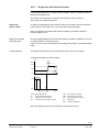
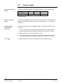
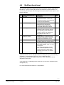
1
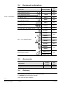
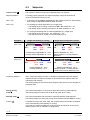
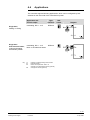
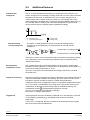
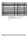
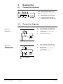
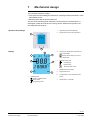
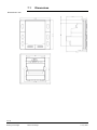
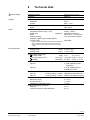
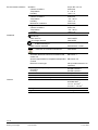
s
Semi-flush-mounted room temperature controllers
for VAV / CAV applications, with LCD
RDU340
Basic Documentation
Edition: 1.0
CE1P3078en
11 July 2008
Building Technologies
2 / 30
Siemens
Building Technologies
Basic Documentation
CE1P3078.en
11 July 2008
Table of contents
1
About this document ..............................................................................4
1.1
Revision history.........................................................................................4
1.2
Reference documents ...............................................................................4
1.3
1.3.1
1.3.2
Before you start.........................................................................................4
Copyright...................................................................................................4
Quality assurance .....................................................................................4
2
Summary..................................................................................................5
2.1
Brief description ........................................................................................5
2.2
Features ....................................................................................................5
2.3
Type summary...........................................................................................5
2.4
Equipment combinations...........................................................................6
2.5
Accessories...............................................................................................6
2.6
Ordering ....................................................................................................6
3
Use............................................................................................................7
4
Functions .................................................................................................8
4.1
Temperature control ..................................................................................8
4.2
Operating modes ......................................................................................9
4.3
Setpoints .................................................................................................10
4.4
Applications............................................................................................. 11
4.5
Additional features ..................................................................................12
4.6
4.6.1
4.6.2
Control sequences ..................................................................................13
Single duct ..............................................................................................13
Single duct with electrical heater ............................................................15
4.7
Control output..........................................................................................16
4.8
Multifunctional input ................................................................................17
4.9
Error handling..........................................................................................18
4.10
DIP switches ...........................................................................................18
4.11
Control parameters .................................................................................19
5
Handling.................................................................................................22
5.1
Mounting and installation ........................................................................22
5.2
Operating Instructions.............................................................................23
5.3
Disposal ..................................................................................................23
6
Engineering ...........................................................................................24
6.1
Connection terminals ..............................................................................24
6.2
Connection diagrams ..............................................................................24
7
Mechanical design ................................................................................25
7.1
Dimensions .............................................................................................26
8
Technical data .......................................................................................27
Index
................................................................................................................29
3 / 30
Siemens
Building Technologies
RDU340… Basic Documentation
Table of contents
CE1P3076.en
11 July 2008
1
About this document
1.1
Revision history
Edition
Date
Changes
1.0
11 July 2008
First edition
1.2
Section
Pages
Reference documents
Ref.
Document titel
Type of document
Document No.
N3078
Datasheet
CE1N3078en
B3076
Semi-flush-mounted room temperature
controllers with LCD
Operating Instructions
M3078
Mounting Instructions
CE1B3076en
CE1M3078xx
1.3
Before you start
1.3.1
Copyright
This document may be duplicated and distributed only with the express permission
of Siemens, and may be passed only to authorized persons or companies with the
required technical knowledge.
1.3.2
Quality assurance
These documents have been prepared with great care.
• The contents of all documents are checked at regular intervals.
• Any corrections necessary are included in subsequent versions.
• Documents are automatically amended as a consequence of modifications and
corrections to the products described.
Please ensure that you are aware of the latest revision date of the documentation.
If you find any lack of clarity while using this document, or if you have any criticisms
or suggestions, please contact the product manager in your nearest branch office,
or write directly to the support team at Headquarters in Zug (see below).
Support address:
Siemens Switzerland Ltd.
Building Technologies Group
International Headquarters
Field Support 5500
Gubelstrasse 22
6301 Zug, Switzerland
Tel. +41 41 724 5500
Fax. +41 41 724 5501
E-mail: [email protected]
4 / 30
Siemens
Building Technologies
RDU340… Basic Documentation
About this document
CE1P3078en
11 July 2008
2
Summary
2.1
Brief description
The devices support VAV heating and cooling systems:
•
•
•
•
•
•
•
•
•
•
•
•
Modulating PI / P control
Control depending on the room or the return air temperature
Output for a DC 0…10 V actuator and AC 230V electrical heater (ON-OFF)
Automatic or manual heating/cooling changeover
Operating modes: Comfort, Energy Saving and Protection
Two multifunctional inputs for keycard contact, external sensor, etc.
Adjustable commissioning and control parameters
Minimum and maximum setpoint limitation
Adjustable minimum and maximum limitation of output signal DC 0..10V
Output signal inversion as an option
Mounting on recessed rectangular conduit box, 60.3 mm fixing centers
AC 24 V operating voltage
2.2
Features
• Maintain room temperature via built-in temperature sensor external room
temperature / return air temperature sensor.
• Automatic or manual changeover between heating and cooling mode.
• Select applications via DIP switches
• Select operating mode via the operating mode button on the controller.
• Display current room temperature or setpoint in °C and/or °F.
• Minimum and maximum setpoint limitation.
• Keypad lock (automatic and manual).
• Two multifunctional inputs, freely selectable for:
– Operating mode switchover contact (key card).
– Automatic heating/cooling changeover sensor.
– External room temperature or return air temperature
– Dewpoint sensor.
– Electric heater enable.
– Alarm input.
• Minimum and maximum limitation of air flow signal DC 0..10V
• Reload factory settings for commissioning and control parameters.
RDU340
Operating Voltage
3 pt
AC 24 V
--
on/off
DC 0..10 V
Housing
Colour r
Control output
Product
number
Infrared
receiver
Type summary
LCD
Backlight
2.3
white
5 / 30
Siemens
Building Technologies
RDU340… Basic Documentation
Summary
CE1P3078en
11 July 2008
2.4
Equipment combinations
Product number
Data
sheet
Cable temperature sensor
QAH11.1
1840
Room temperature sensor
QAA32
1747
SSA61...
4893
SSP61…
4864
SSB61...
4891
SQS65…
4573
STS61
4880
GQD161…
4605
Type of unit
DC 0..10 V actuators
Electrical actuator, DC 0..10V
(for radiator valve)
Electrical actuator, DC 0..10V
(for small valve 2,5 mm)
Electrical actuator, DC 0..10V
(for small valves 5.5 mm)
Electromotoric actuator, DC 0..10V
(for valves 5.5 mm)
Thermal actuator, DC 0..10V
(for small valves and radiator valves)
GDB161…
4634
GLB161…
GMA161…
4614
GEB161…
4621
GCA161…
4613
DC 0…10 V damper actuator
GBB161…
4626
GIB161…
GDB181.1E/3
3544
VAV compact controller
GLB181.1E/3
2.5
Accessories
Type of unit
Changeover sensor mounting kit (50 pcs/package)
Adapter plate 82mm x 82 mm x 10 mm for conduit
2.6
Product
number
ARG86.3
ARG70.3
Data
sheet
1840
--
Ordering
When ordering, indicate both product number and name:
E.g. RDU340 room temperature controller
Order valve actuators separately.
6 / 30
Siemens
Building Technologies
RDU340… Basic Documentation
Summary
CE1P3078en
11 July 2008
3
Use
Control of the room temperature in individual rooms of ventilation or air
conditioning plants that are:
• Heated or cooled by single duct.
• Heated and cooled by single duct with auxiliary electrical heater.
The RDU340 is suitable for use with VAV systems in connection with the VAV
compact controllers types G…B181.1E/3.
The RDU340 controls
• One DC 0…10 V actuator
• One DC 0…10 V actuator and AC 230V 1-stage electrical heater
Use in systems with:
•
•
•
•
Heating or cooling mode
Automatic heating/cooling changeover
Manual heating/cooling changeover
Heating and cooling (single duct with electrical heater)
7 / 30
Siemens
Building Technologies
RDU340… Basic Documentation
Use
CE1P3078en
11 July 2008
General note
4
Functions
4.1
Temperature control
The setting of he control parameters (P01 etc., mentioned throughout the
document) is described in section 4.11.
The controller acquires the room temperature via built-in sensor, external room
temperature sensor (QAA32), or external return air temperature sensor (QAH11.1),
and maintains the setpoint by issuing actuator control commands to heating and/or
cooling equipment. The following control outputs are available:
• Modulating PI / P control with DC 0..10 V control output for actuators and ONOFF for electrical heater.
The switching differential or proportional band is 2 K for heating mode and 1 K for
cooling mode (adjustable via parameters P30 and P31).
The integral action time for continuous PI control is 5 minutes (adjustable via
parameter P35).
Display
/
Concurrent display of
°C and °F
The display shows the acquired room temperature or the setpoint for the current
operating mode, selectable via parameter P06. The factory setting displays the
current room temperature.
Use parameter P04 to display the room temperature or setpoint in °F rather than
°C as needed.
If the controller is used in a system with manual heating/cooling changeover
(P01=2), the heating and cooling
symbols on the display show the terminal
unit status. Thus, the symbols are displayed even when the controller operates in
the neutral zone. For all other cases, the heating and cooling
symbols are
displayed when the heating or cooling output is energized.
Concurrent display of the current temperature or setpoint in °C and in °F
(parameter P07) is possible on the controller without weekly time program.
8 / 30
Siemens
Building Technologies
RDU340… Basic Documentation
Functions
CE1P3078en
11 July 2008
4.2
Operating modes
Select the controller's operating mode via operating mode button on the
controller or operating mode input (e.g. keycard occupancy sensor, when X1 or X2
set to 3 (P38, P40)). A corresponding setpoint is used to maintain the room
temperature at the desired level depending on the active operating mode. The
following operating modes are available:
Comfort mode
In Comfort mode, the controller maintains the setpoint which can be adjusted via
the +/- buttons.
Energy Saving
Energy Saving mode helps save energy. Select it by pressing the operating mode
button if parameter P02 is set accordingly, or if the external operating mode
switchover contact is active (e.g. window contact).
If the external operating mode switchover contact is active, user operations are
ineffective and “OFF” is displayed. Control will then be according to energy saving
setpoints (P11 and P12).
Note
Standby
/Protection mode
In Standby mode, the system is
– protected against frost (factory setting 8 °C, can be disabled or changed via P65).
– protected against overheating (factory setting OFF, can be enabled or changed
via P66)
9 / 30
Siemens
Building Technologies
RDU340… Basic Documentation
Functions
CE1P3078en
11 July 2008
4.3
Setpoints
Comfort mode
The setpoint in Comfort mode can be adjusted via the +/- buttons.
Setpoint limitation
For energy saving purposes, the setpoint adjusting range can be limited to
minimum (P09) and maximum (P10).
P09 < P10
• If the minimum limit P09 is set lower than the maximum limit P10, both heating
and cooling are adjustable between these two limits.
P09 ≥ P10
• For heating or cooling applications (e.g. single duct)
– The setting range in cooling mode is from P09…40° instead of 5…40°
– The setting range in heating mode is from 5…P10° instead of 5…40°
• For cooling and heating with el. heater applications (e.g. single duct)
– The setting range is from P09…40° instead of 5…40°
– The setpoint for the el. heater is maximal limited by P10
Examples
Single duct heating or cooling
Single duct cooling with el heater
P09 < P10
5°C
18°C
P09
25°C
P10
40°C
Cooling setpoint adjustable 18…25°C
Heating setpoint adjustable 18…25°C
5°C
18°C
P09
25°C
P10
40°C
Setpoint adjustable 18…25°C
Heating setpoint := Cooling setpoint –
dead zone
P09 ≥ P10
5°C
21°C
P10
25°C
P09
Cooling settable 25…40°C
Heating settable 5…21°C
Temporary setpoint
40°C
5°C
21°C
P10
25°C
P09
40°C
Setpoint adjustable 25…40°C
Heating setpoint := Cooling setpoint –
dead zone, but max (limited by) P10
If the “Temporary setpoint function” is enabled via parameter P69, the setpoint
adjusted via the +/- buttons is set back to the Comfort basic setpoint when the
operating mode changes.
The factory setting for the Comfort basic setpoint is 21 °C and can be changed via
parameter P08.
Energy Saving
mode
Use control parameters P11 and P12 to adjust the Economy mode setpoints.
The heating setpoint is factory-set to 15 °C and to 30 °C for cooling.
Standby mode
Use control parameters P65 and P66 to adjust the Standby mode setpoints.
The heating setpoint is factory-set to 8 °C (frost protection) and to OFF for cooling.
Caution
If a setpoint is set to OFF (P65, P66), the controller does not maintain the setpoint
in the corresponding mode (heating or cooling).
This means no protective heating or cooling function and thus risk of frost in the
heating mode or risk of overheat in cooling mode!
10 / 30
Siemens
Building Technologies
RDU340… Basic Documentation
Functions
CE1P3078en
11 July 2008
4.4
Applications
The controller supports following applications, which can be configured by DIPswitches on the inner side of the controller front panel.
Application and
Control output
modulating, DC 0…10 V
Type
reference
RDF340
Single duct,
heating or cooling
DIPswitch
Diagram
ON
B2
1
2
V
M
Y10
B1
Single duct
with electrical heater,
cooling and heating,
with auxiliary heater
modulating, DC 0…10 V
RDF340
Note: on-off electrical heater
ON
1
2
V
M
Y21
Y10
B1
Key
Y1
E1
B1
B2
Heating or heating/cooling valve actuator
Electrical heater
Return air temperature sensor or
external room temperature sensor (optional)
Changeover sensor (optional)
11 / 30
Siemens
Building Technologies
RDU340… Basic Documentation
Functions
CE1P3078en
11 July 2008
4.5
Automatic H/C
changeover
Additional features
The air or water temperature acquired by the changeover sensor (QAH11.1) is
used to change over from heating to cooling mode and vice-versa. When the water
temperature is above 28 °C (parameter P37), the controller changes over to
heating mode, and to cooling mode when below 16 °C (parameter P36). If the
water temperature is between the 2 changeover points immediately after power up,
the controller starts in heating mode. The water temperature is acquired at 30second intervals and the operating state is updated accordingly.
M
16
Tw[°C]
28
M Operating mode
Tw Air or water temperature
Remote heating/
cooling changeover
Cooling mode
Heating mode
The QAH11.1 cable temperature sensor for automatic heating/cooling
changeover can be replaced by an external switch for manual, remote
changeover:
X2
M
T
QAH11.1
Contact open
X2
M
3076Z03
Contact closed
heating mode
cooling mode
T °C
The sensor or switch can be connected to the input terminal of X2 (factory setting)
or X1 depending on the commissioning of inputs X1 and X2. See also section
“Multifunctional input”.
External/return
temperature sensor
The controller acquires the room temperature via built-in sensor, external room
temperature sensor (QAA32), or external return air temperature sensor (QAH11.1)
connected to multifunctional input X1 or X2.
Inputs X1 or X2 need to be commissioned accordingly. See section 4.8 “Multifunctional input”.
Dewpoint monitoring
Dewpoint monitoring is essential to prevent condensation on the chilled ceiling and
help avoid associated damage to the building. This is an optional function and is
provided in case the controller is used for a chilled ceiling application.
A dewpoint sensor with a voltage-free contact is connected to multifunctional input
X1 or X2. If there is condensation, the cooling valve is fully closed until no more
condensation is detected and the cooling output is disabled temporarily. The
condensation symbol is displayed during temporary override.
Input X1 or X2 must be commissioned accordingly.
See section “4.8 Multifunctional input”.
Keypad lock
If the keypad lock function is enabled by parameter P14, then pressing 7 seconds
on the operating mode button , the keypad will be locked or unlocked
respectively.
If “Auto lock” is configured, then the controller will automatically lock the keypad
after 30 seconds of the last adjustment.
12 / 30
Siemens
Building Technologies
RDU340… Basic Documentation
Functions
CE1P3078en
11 July 2008
Min / Max air flow
The output signal of the air flow (DC 0..10V) can be limited to a minimum value by
using parameter P63 and to a maximum value using parameter P64. These air flow
limitation values can be set between 0% and 100%.
This is used to ensure a minimum or maximum supply air volume.
Changeover
Y10
100%
XpH
H
XpC
T
Y10
W
XpH
XpC
Vmin
Vmax
C
max
Vmax
min
Vmin
Room temperature
Control output
Room temperature setpoint
Proportional band Heating
Proportional band Cooling
Minimum limitation air flow
Maximum limitation air flow
0%
W
Output signal inversion
TR [°C]
The output signals DC 0…10V can be inverted by means of DIP switch #2.
– If DIP switch #2 is set to “OFF”, 0V corresponds to 0% travel and 10V to 100%
(factory settting).
– In position ON, 0V corresponds to 100% travel and 10V to 0% travel.
This function is useful in conjunction with normally open valves.
4.6
Control sequences
4.6.1
Single duct
If the selected application is "single duct", then the controller can be used in
systems featuring:
– Heating or cooling mode (P01=0 or P01=1).
– Manual heating/cooling changeover (P01=2).
– Automatic heating/cooling changeover (P01=3).
The relevant modes can be adjusted via commissioning parameter “Control
sequence” P01, depending on the selected application.
Sequence
T
T °C
T °C
Parameter
Mode
P01 = 0
Heating mode
P01 = 1
Cooling mode
Available for:
Single duct
T °C
P01 = 2
Manually select
heating or cooling
mode
T °C
P01 = 3
Automatic
heating/cooling
changeover via
external water
temperature
sensor or remote
switch
In application "Single duct with el. heater", the controller operates in heating AND
cooling mode.
13 / 30
Siemens
Building Technologies
RDU340… Basic Documentation
Functions
CE1P3078en
11 July 2008
Single duct,
heating or cooling
In single duct applications, the controller controls an actuator (valve, damper, VAV
system, etc)
– in heating/cooling mode with changeover (automatic or manual),
– heating only mode,
– or cooling only mode.
Cooling only is factory set (P01=1).
The output can be limited to a minimum and maximum value if required.
See section 4.5 "additional features".
The diagram below shows the control sequence for continuous PI control.
Heating only mode
H
100%
Y10
XpH
XpC
100%
max
Vmax
Vmax
Vmin
min
Vmin
0%
C
max
Y10
Cooling only mode
min
Control sequence
modulating output
0%
W
TR [°C]
W
TR [°C]
Changeover
Changeover
Y10
100%
H
XpH
XpC
C
max
Vmax
min
Vmin
0%
W
T[°C]
w
Y10
XpH
XpC
Vmin
Vmax
Note
TR [°C]
Room temperature
Room temperature setpoint
Control command “Valve”
Proportional band “Heating”
Proportional band “Cooling”
Min. limitation for output
Max. limitation for output
The diagrams show the PI controller’s proportional part only
14 / 30
Siemens
Building Technologies
RDU340… Basic Documentation
Functions
CE1P3078en
11 July 2008
4.6.2
Single duct with electrical heater
If the selected application is "single duct & el. heater", then the controller works in
heating and cooling mode.
The output can be limited to a minimum and maximum value if required.
See section 4.5 "additional features".
Single duct
with el. heater
In single duct applications with electrical heater, the controller controls an actuator
(valve, damper, VAV system, etc.) plus an auxiliary electrical heater.
Note: The setpoint for the electrical heater is limited by parameter “Maximum
heating setpoint” (P10).
Digital input “Enable
electrical heater”
Remote enabling/disabling of the electrical heater is possible via digital input X1/X2
for tariff regulations, energy saving etc.
Input X1 or X2 must be commissioned accordingly. See section “4.9 Multifunctional
input”.
Control sequence
The diagram below shows the control sequence for continuous PI control.
Cooling and heating with electric heater
Y10
XpC
100%
max
Vmax
min
Vmin
0%
TR [°C]
Y21
SDH
ON
OFF
W
dz
TR [°C]
TR[°C] Room temperature
Vmin
W
Vmax Max. limitation for output
Room temperature setpoint
Min. limitation for output
Y10
Control command “actuator”
XpC
Proportional band “Cooling”
Y21
Control command “electrical heater”
Xdz
Dead zone
SDH
Switching differential
Note: The diagrams show the PI controller's proportional part only.
15 / 30
Siemens
Building Technologies
RDU340… Basic Documentation
Functions
CE1P3078en
11 July 2008
4.7
Overview of control
output
Control output
Different control output signals are available depending on the controller type.
Control output
on/off
3-position
DC 0…10 V
Type reference
RDU340
Y21 (1)
--
Y10 (1)
( ) Number of outputs
DC 0..10 V control
signal
The demand calculated by the PI control from the current room temperature and
setpoint is provided to the valve actuator as a continuous DC 0...10 V signal via
output Y10.
Electrical heater
control signal
(2-position)
The electrical heater receives an ON command via the auxiliary heating control
output Y21:
1. When the acquired room temperature is below “setpoint for electric heater”.
2. When the electrical heater has been switched off for more than 1 minute.
The OFF command for the electrical heater is output:
1. When the acquired room temperature is above the setpoint (electric heater).
2. When the electrical heater has been switched on for more than 1 minute.
Caution
A safety thermostat (to prevent overheating) must be provided externally.
16 / 30
Siemens
Building Technologies
RDU340… Basic Documentation
Functions
CE1P3078en
11 July 2008
4.8
Multifunctional input
The controller offers two multifunctional inputs X1 and X2. A sensor of type NTC
like QAH11.1 (AI) or a switch (DI) can be connected to the input terminals. The
functionality of both inputs can be configured via parameters P38 for input X1 and
P40 for input X2.
#
0
1
Function of input X1/X2
Not used
External/Return air temp.
2
Heat/cool changeover
3
Operating mode switchover
4
Dewpoint monitor
5
Enable electrical heater
6
Alarm
Description
No function.
Sensor input external room
temperature sensor or return air
temperature sensor to measure the
current room temperature.
Sensor input for automatic
heating/cooling changeover
function. A switch can also be
connected rather than a sensor.
Digital input to switch over the
operating mode to Energy Saving.
If the operating mode switchover
contact is active, user operations
are ineffective and “OFF” is
displayed.
Digital input for a dewpoint sensor
to detect condensation. Cooling is
stopped if condensation occurs.
Digital input to enable/disable the
electrical heater via remote control.
Digital input to signal an alarm.
If the input is active, “ALx” (x:=1 or 2)
is displayed.
Note: Alarm displays do not influence controller operations. They
merely represent a visual signal.
Example: No air flow or el. heater
overheated.
Type
AI
AI/(DI)
DI
DI
DI
DI
Operational action can be changed between normally open (N.O.) and normally
closed (N.C.) via parameter P39 or P41 if it is a digital input (DI).
Each function can only be assigned to input X1 or X2; only “Alarm” can be
assigned to both inputs.
X1 is factory-set to “Operating mode switchover” (3) and X2 to “Heating/cooling
changeover” (2).
For more information see section 4.4 “Applications”.
17 / 30
Siemens
Building Technologies
RDU340… Basic Documentation
Functions
CE1P3078en
11 July 2008
4.9
Temperature out of
range
Error handling
When the room temperature is outside the measuring range, i.e. above 49 °C or
below 0 °C, the limiting temperatures flash, e.g. “0 °C” or “49 °C”.
If the temperature is below 0 °C and the controller is in heating mode and the
current setpoint is not set to “OFF”, then the control output Y10 or Y21 respectively
will issue actuator control commands to heating equipment.
For all other cases, the control output is de-energized. The controller resumes
Comfort mode after the temperature returns to within the measuring range.
4.10
ON
1
2
DIP switches
Use the DIP switches on the inner side of the front panel to commission the basic
controller applications prior to snapping it to the base.
DIP switch number
1
2
OFF
ON
n.a.
n.a.
n.a.
n.a.
OFF
ON
Application
Single duct (factory setting)
Single duct & electrical heater
DC 0…10 V output signal normal (factory setting)
DC 0…10 V output signal inverted (see section 4.5)
Note: During startup, the controller reloads the control parameter factory settings
after each DIP switch settings change.
18 / 30
Siemens
Building Technologies
RDU340… Basic Documentation
Functions
CE1P3078en
11 July 2008
4.11
Control parameters
A number of control parameters can be readjusted to optimize control performance.
These parameters can also be set during operation without opening the unit. In the
event of a power failure, all control parameter settings are retained.
The control parameters are divided in two levels:
• “Service” level, and
• “Expert” level.
The “Service” level contains a small set of parameters to set up the controller for
the HVAC system and to adjust the user interface. These parameters can usually
be adjusted any time.
Change parameters in the “Expert” level only carefully, as they impact control
performance and functionality of the controller.
Change the parameters as follows:
Parameter setting
Enter only “Service”
level
1. Set the controller to Standby
*)
2. Press buttons + and - simultaneously for 3 seconds. Release and press
button + again for 3 seconds within 2 seconds. The display shows “P01”.
Continue at Step 3.
Enter “Service” and
“Expert” level.
1. Set the controller to Standby
*)
2. Press buttons + and - simultaneously for 3 seconds. Release and press
button - again for 6 seconds within 2 seconds. The display shows “P01”
and service.
Adjust parameters
3. Select the required parameter by repeatedly pressing buttons + and -.
4. When you press buttons + and - simultaneously, the current value of the
selected parameter starts to flash, which can be changed by repeatedly
pressing buttons + or -.
5. When you again press buttons + and – simultaneously, the next parameter
is displayed.
6. Repeat Steps 3 to 5 to display and change additional parameters.
7. All changes are saved and the controller returns to Standby 10 seconds
after the last display or setting.
The factory setting for the control parameters can be reloaded via parameter P71,
by changing the value to “ON”, and confirming by pressing buttons + and –
simultaneously. The display shows “8888” during reload.
Reset parameters
Note!
*) If one of the digital inputs is commissioned as window contact, and the contact is
closed, the controller will switch to ECO mode and parameter setting will not be
possible. Solution: open the window contact.
19 / 30
Siemens
Building Technologies
RDU340… Basic Documentation
Functions
CE1P3078en
11 July 2008
#
Factory
setting
Parameter
Service Level
P01
Control sequence
(for application "single duct" only)
1 (Cooling only)
P02
Mode selection via user operating mode button
1 (Stb, Comf)
P04
Selection of °C or °F
°C
Setting range
0:= Heating only
1:= Cooling only
2:= Manual H/C
3:= Auto changeover
1 = Stb,Comf
2 = Stb, Comf, Eco
(0) °C
(1) °F
– 3 ... +3 K
P05
Sensor calibration
0.0 K
P06
Standard temperature display
0 (Room temp)
P07
Additional user info
0 (no display)
P08
Comfort basic setpoint
21 °C
0:= Room temperature
1:= Setpoint
0:= no display
1:= Temp in °C and °F
5 ... 40 °C
P09
Minimum setpoint limitation for Comfort (WminComf)
5 °C
5 ... 40 °C
P10
Maximum setpoint limitation for Comfort (WmaxComf)
35 °C
5 ... 40 °C
P11
Heating setpoint for Energy Saving
(WheatEco)
15 °C
OFF, 5 °C…WcoolEco
P12
Cooling setpoint for Energy Saving
(WcoolEco)
30 °C
OFF, WheatEco…40 °C
P14
Keypad lock
(Press the operating mode button
or disable the keypad lock)
0 (Unlocked)
0:= Unlocked
1:= Auto lock
2:= Manual lock
Note
for 7 seconds to enable
RDU340
Control parameters
• P01 is not available when the controller is commissioned as single duct with el.
heater (DIP switch #1 = ON)
• P02 is not available when the controller is commissioned for manual
heating/cooling changeover (P01=2)
• Parameter display depends on selected application and function
(x) Not available
20 / 30
Siemens
Building Technologies
RDU340… Basic Documentation
Functions
CE1P3078en
11 July 2008
Factory
setting
Parameter
Expert Level
P30
P-band/switching differential for heating mode
P31
P-band/switching differential for cooling mode
P33
Dead zone in Comfort mode
P35
Integral time
P36
Heating/cooling changeover switching point for cooling
P37
Heating/cooling changeover switching point for heating
P38
X1 functionality
2K
1K
2K
5 min
16 °C
28 °C
3 (Op mode
switchover)
P39
Operating action for X1 if digital input
0 (N.O.)
P40
P41
X2 functionality
Operating action for X2 if digital input
2 (H/C c/o)
0 (N.O.)
P63
P64
P65
P66
P69
Minimum output limitation air flow signal (0..10V)
Maximum output limitation air flow signal (0..10V)
Heating setpoint for Standby
(WheatStb)
Cooling setpoint for Standby
(WcoolStb)
Temporary setpoint for Comfort mode
0%
100%
8 °C
OFF
OFF
P71
Parameter reset
Set value to ON and confirm by pressing the + and – buttons
OFF
Diagnostic & Test
d01
Application
Diagnose
d02
Status input X1
Diagnose
d03
Status input X2
Diagnose
RDU340
#
Setting range
0.5 … 6 K
0.5 … 6 K
0.5 … 5 K
0…10 min
10…25 °C
27…40 °C
0:= NA
1:= Ext/Return air temp
2:= Heat/cool changeover
3:= Operating mode switch
4:= Dewpoint monitor
5:= Enable electrical heater
6:= Alarm input
0:= Normally open
1:= Normally closed
Same as P38
0:= Normally open
1:= Normally closed
0…100%
0…100%
OFF, 5 °C…WcoolStb
OFF, WheatStb …40 °C
OFF:= Disabled
ON := Enable
OFF:= Idle
ON: = Reset
2P:= single duct
2PEL:= single duct & el. heater
0:= Digital input not activated
1:= Digital input activated
0…49 °C = measured temp. value
00 := H/C input short
100:= H/C input open
Same as d02
21 / 30
Siemens
Building Technologies
RDU340… Basic Documentation
Functions
CE1P3078en
11 July 2008
5
Handling
5.1
Mounting and installation
Mount the room controller on a recessed rectangular conduit box with 60.3mm
fixing centers. Do not mount on a wall in niches or bookshelves, behind curtains,
above or near heat sources, or exposed to direct solar radiation. Mount about
1.5 m above the floor.
Mounting
• Devices must be mounted on clean, dry indoor place and not be exposed to
dripping or splashing
Wiring
See the mounting instructions M3076 enclosed with the controller.
• Comply with local regulations to wire, fuse and earth the controller.
• Properly size the cables to electrical heater for AC 230 V mains voltage.
• Isolate the cables of SELV inputs X1-M/X2-M if the conduit box carries AC 230 V
mains voltage.
• Inputs X1-M or X2-M of different units (e.g. summer/winter switch) may be
connected in parallel with an external switch. Consider overall maximum contact
sensing current for switch rating.
• No metal conduits
• No cables provided with a metal sheath
• Disconnect from supply before opening the cover
Commissioning
Set the controller application via the DIP switches before snapping the front panel
on the mounting base.
After power is applied, the controller carries out a reset during which all LCD
segments flash indicating that the reset was correct. After the reset, which takes
about 3 seconds, the controller is ready for commissioning by qualified HVAC staff.
The control parameters of the controller can be set to ensure optimum performance
of the entire system (see “Set control parameters”).
Control sequence
• The control sequence may need to be set via parameter P01 depending on the
application. The factory setting for the single duct application is “Cooling only”.
Calibrate sensor
• Recalibrate the temperature sensor if the room temperature displayed on the
controller does not match the room temperature measured. To do this, change
parameter P05.
Setpoint and range
limitation
• We recommend to review the setpoints and setpoint ranges (parameters
P08…P12) and change them as needed to achieve maximum comfort and save
energy.
22 / 30
Siemens
Building Technologies
RDU340… Basic Documentation
Handling
CE1P3078en
11 July 2008
5.2
Operating Instructions
See the operating instructions B3076 enclosed with the controller.
5.3
Disposal
The device is classified as waste electronic equipment in terms of the European
Directive 2002/96/EC (WEEE) and should not be disposed of as unsorted municipal waste.
The relevant national legal rules are to be adhered to. Regarding disposal, use
the systems setup for collecting electronic waste.
Observe all local and applicable laws.
23 / 30
Siemens
Building Technologies
RDU340… Basic Documentation
Handling
CE1P3078en
11 July 2008
6
Engineering
6.1
Connection terminals
G
X1
M
X2
SELV
L Y21
G0
Y10 G0
G, G0
L
230 V
Y21
Y10
X1, X2
M
6.2
Application:
Operating voltage controller AC 24 V
Operating voltage for electrical heater AC
Control output for electrical heater
Control output for DC 0…10 V actuator
Multifunctional input for temperature
sensor (e.g. QAH11.1) or switch
Measuring neutral for sensor and switch
Connection diagrams
G
Single duct
B2
S1
AC 24V
N1
Y1
S1
QAH11.1 +
ARG86.3
G
X1
M
B2
X2
L Y21
G0
Y10
G0
Room temperature controller RDU340...
DC 0-10V actuator for heating or cooling
Operating mode switch-over contact
(e.g. key card)
Heat/cool changeover sensor
N1
Y1
G0
G - G0 AC 24 V
Application:
G
N1
Y1
E1
S1
QAH11.1 +
/ QAA32
Single duct with
electrical heater
AC 24V
S1
G
X1
M
X2
B2
G0
L Y21
Y10
G0
Room temperature controller RDU340...
DC 0-10V actuator for heating or cooling
Electrical heater
Operating mode switch-over contact
(e.g. key card)
Heat/cool changeover sensor
N1
L
N
Y1
E1
G0
G - G0 AC 24 V
L - N AC 230 V
24 / 30
Siemens
Building Technologies
RDU340… Basic Documentation
Engineering
CE1P3078en
11 July 2008
7
Mechanical design
The controller consists of 2 parts:
• Front panel accommodating the electronics, operating elements and built-in room
temperature sensor.
• Mounting base with the power electronics.
The rear of the mounting base contains the screw terminals. The base fits on a
rectangular conduit box with 60.3 mm fixing centers. Slide the front panel in the
mounting base and snap on.
Operation and settings
1
1.
Operating mode selector/Standby
2.
Adjust setpoint and control parameters
2.
Display room temperature, setpoints and
2
Display
6
control parameters.
3
1
Symbol used to display the current
room temperature
2
4
3.
Heating/cooling mode
Cooling mode
Heating mode,
Electrical heater active
7
1.
5
4.
Additional user information
5.
Keypad lock active
6.
Condensation in room (dewpoint sensor
Operating mode
Standby / protected mode
Comfort mode
active)
7.
Indicate alarm or reminder
Energy Saving mode
25 / 30
Siemens
Building Technologies
RDU340… Basic Documentation
Mechanical design
CE1P3078en
11 July 2008
7.1
Dimensions
Dimensions in mm
26 / 30
Siemens
Building Technologies
RDU340… Basic Documentation
Mechanical design
CE1P3078en
11 July 2008
8
Power supply
Outputs
Inputs
Technical data
Operating voltage
Frequency
Power consumption
Control output Y10-G0
Resolution
Current
Control output Y21-L (N.O.)
Rating
Multifunctional input X1-M/X2-M
Temperature sensor input: Type
Digital input:
Operating
action
Contact sensing
Insulation against mains voltage (SELV)
Function input:
External temperature sensor, heating/cooling changeover
sensor, operating mode switchover contact, dewpoint
monitor contact, enable electrical heater contact, alarm
contact
Operational data
Switching differential, adjustable
Heating mode
Cooling mode
Setpoint setting and range
Comfort mode
Energy Saving mode
Standby
Multifunctional input X1/X2
Input X1
(P30)
(P31)
(P08)
(P11-P12)
(P65-P66)
Input X2
Multifunctional input X1/X2
Selectable 0…6
Input X1
Factory setting = 3 (P38)
Input X2
Factory setting = 2 (P40)
Built-in room temperature sensor
Measuring range
Accuracy at 25 °C
Temperature calibration range
Settings and display resolution
Setpoints
Current temperature value displayed
SELV AC 24 V ± 20 %
50/60 Hz
Max. 8 VA
SELV DC 0…10 V
39 mV
Max. ± 1 mA
AC 230 V
Max. 5(2) A
QAH11.1 (NTC)
Selectable (N.O./N.C.)
SELV DC 0...5 V/max 5 mA
4 kV, reinforced insulation
Selectable
2 K (0.5...6K)
1 K (0.5...6K)
21°C
(5...40 °C)
15°C/30°C (OFF, 5...40 °C)
8°C/OFF (OFF, 5...40 °C)
Selectable 0…6
3: (P38) operating mode
switchover
2: (P40) heating/cooling
changeover sensor
Operating mode switchover
Heat/cool changeover sensor
0…49 °C
< ± 0.5 K
± 3.0 K
0.5 °C
0.5 °C
27 / 30
Siemens
Building Technologies
RDU340… Basic Documentation
Technical data
CE1P3078en
11 July 2008
Environmental conditions
Standards
Operation
Climatic conditions
Temperature
Humidity
Transport
Climatic conditions
Temperature
Humidity
Mechanical conditions
Storage
Climatic conditions
Temperature
Humidity
conformity
EMC directive
Low-voltage directive
As per IEC 721-3-3
Class 3K5
0 ...+ 50 °C
< 95 % r.h.
As per IEC 721-3-2
Class 2K3
− 25...+60 °C
< 95 % r.h.
Class 2M2
As per IEC 721-3-1
Class 1K3
− 25...+60 °C
< 95 % r.h.
2004/108/EC
2006/95/EC
N474
C-tick conformity to
EMC emission standard
Reduction of hazardous substances
Product standards
Automatic electrical controls for household and
similar use
Special requirements for temperature-dependent
controls
Electronic control type
General
Electromagnetic compatibility
Emissions
Immunity
Protective class
Pollution class
Degree of protection of housing
Connection terminals
Housing front color
Weight
AS/NSZ 4251.1:1999
2002/95/EC
EN 60730–1
EN 60730–2-9
2.B (microdisconnection on
operation)
IEC/EN 61000-6-3
IEC/EN 61000-6-2
II as per EN 60730
Normal
IP 30 to EN 60529
Solid wires or prepared
stranded wires
1 x 0.4…2.5 mm2
or 2 x 0.4…1.5 mm2
RAL 9003 white
0.220 kg
28 / 30
Siemens
Building Technologies
RDU340… Basic Documentation
Technical data
CE1P3078en
11 July 2008
Index
A
Adapter plate .......................................................... 6
Alarm .................................................................... 17
Automatic H/C changeover................................... 12
Automatic heating/cooling changeover................. 13
C
Calibrate sensor.................................................... 22
Comfort mode ......................................................... 9
Commissioning ..................................................... 22
Control output ......................................................... 5
Control parameters ............................................... 19
Cooling mode........................................................ 13
D
DC 0..10 V control signal ................................... 16
Dewpoint............................................................... 17
Digital input ........................................................... 17
DIP switches ......................................................... 18
E
Electrical heater ............................................ 11, 15
Enable electrical heater ........................................ 15
Enable/disable the electrical heater...................... 17
Energy Saving ........................................................ 9
Expert level parameters........................................ 19
External/Return air temp....................................... 17
External/return temperature sensor...................... 12
H
Heat/cool changeover........................................... 17
Heating mode ....................................................... 13
Housing color.......................................................... 5
I
Integral action time ................................................. 8
K
Keypad ..................................................................12
M
Manually select heating or cooling mode ..............13
Min / Max air flow ..................................................13
Modulating output..................................................14
Mounting and installation.......................................22
Multifunctional inputs.............................................17
O
On/off control output signals..................................16
Operating mode button............................................9
Operating mode input..............................................9
Operating mode switchover ..................................17
Operating voltage ....................................................5
Output signal inversion..........................................13
P
Parameter setting ..................................................19
Proportional band ....................................................8
R
Remote heating/ ....................................................12
Reset parameters..................................................19
S
Sensor input ..........................................................17
Service level ..........................................................19
Setpoint and range limitation.................................22
Setpoint limitation ..................................................10
Single duct ...........................................................11
Standby /Protection mode .......................................9
Switching differential ...............................................8
T
Temperature out of range......................................18
Temporary setpoint................................................10
29 / 30
Siemens
Building Technologies
RDU340… Basic Documentation
Index
CE1P3078en
11 July 2008
Siemens Switzerland Ltd.
Building Technologies Division
International Headquarters
Gubelstrasse 22
CH-6301 Zug
Tel. +41 41-724 24 24
Fax +41 41-724 35 22
www.siemens.com/sbt
© 2008 Siemens Switzerland Ltd.
Subject to change
30 / 30
Siemens
Building Technologies
RDU340… Basic Documentation
CE1P3078en
11 July 2008


![[ For FX951-51 -up ] Service Manual](http://vs1.manualzilla.com/store/data/006022140_1-0f4cb22e78fbda3a4f7c4fb90e43baab-150x150.png)