1
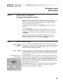
FDS 310
User Manual
1
V 2.0
JMK
9 August 1996
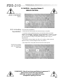
This equipment has been tested and found to comply with the following European Standards for
Electromagnetic Compatibility:
Emission Specification:
EN55013
(1990)
(Associated equipment)
Immunity Specification:
EN50082/1
(1992)
(RF Immunity, Fast Transients and ESD)
Mains Disturbance:
EN61000/3/2
(1995)
For continued compliance ensure that all input and output cables are wired with cable screen connected to Pin
1 of the XLR. The input XLR Pin 1 on BSS equipment is generally connected to chassis via a capacitor to
prevent ground loops whilst ensuring good EMC compatibility.
We have written this manual with the aim of helping installers, sound engineers and musicians to get to grips
with the FDS-310 and obtain its maximum capability.
If you are new to BSS products, we recommend that you begin at the start of the manual. If, however, you are
already familiar with the intended application, and just want to get the unit installed without delay, then
follow the highlighted sections.
We welcome any comments or questions regarding the FDS-310 or other BSS products, and you may contact us
at the address or World Wide Web site given in the warranty section.
2
Contents
Contents
1.0
What is a Crossover?
5
2.0
The difference between Active
and Passive Crossovers
6
3.0
Other advantages
7
4.0
The Linkwitz-Riley advantage
8
5.0
What is special about BSS
Crossovers?
9
6.0
Unpacking
9
7.0
Mechanical Installation
12
8.0
Mains Power Connection
13
9.0
Input Connections
14
9.1
9.2
10.0
10.1
10.2
11.0
11.1
11.2
11.3
13.0
Using Jack Plugs.
Using XLR Plugs.
Output Connections
Using Phone Plugs
Using XLR Plugs
Connection and Setup
Selecting '2-Way' 2 Channel Operation
Selecting '3-Way' Mono Operation
2-Channel Sub-Woofer Operation
Unusual Crossover Points for 3-way systems only
14
14
15
15
15
16
16
17
18
19
12.0
Monaural Sub-Woofer Operation for stereo 2-way systems only
19
14.0
How to Equalise CD Horns
20
15.0
Full range Output 3-way operation only
21
3
Contents
16.0
16.1
16.2
17.0
LED indicators
'Signal Present'
'Peak'
21
21
Crossover Alignment Procedure:
Setting the level controls
22
18.0
Using the Mute switch
24
19.0
Polarity switching and Output
Polarity reversal option
25
20.0
Troubleshooting
26
21.0
Grounding/Earthing Procedures
(Curing hums)
27
Service Section
28
22.0
22.1
22.2
22.3
22.4
22.5
2-Channel Sub-Woofer Operation
Mono-Low/Linking switch
Activating Equalisation
Eliminating Hum
Polarity Switching
28
28
29
30
30
23.0
Glossary
31
24.0
Specifications
33
25.0
Warranty Information
34
Index
35
User Notes
37
Spare Parts Information
4
21
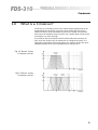
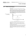
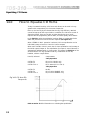
Crossovers
1.0
What is a Crossover?
Crossovers are a necessary part of sound reinforcement systems because the
loudspeaker drive-unit which can produce clear reliable high SPL (sound
levels) over the full audio bandwidth has yet to be invented. All real-world
drive units work best when they are driven over a limited band of frequencies,
for example: Low, Mid and High.
Any crossover aims to provide the division of the audio band necessary, so
each drive unit receives only the frequencies it is designed to handle. In a
high power, high performance sound system, the crossover should also reject
unsuitable frequencies to avoid damage and poor quality sound.
Fig 1.1 Stereo 2-way
Crossover set-up
Fig 1.2 Mono 3-way
Crossover set-up
5
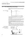
Active and Passive Crossovers
2.0
The difference between Active and
Passive Crossovers
Passive crossovers divide the frequency spectrum after the signal has been
raised to a high power level. They are generally heavy, bulky and inefficient.
Active crossovers utilise ICs and transistors, and divide the frequency
spectrum at line levels immediately ahead of the amplifiers (See Figure 2.1).
An active crossover does the same job as a passive crossover, but with more
precision, flexibility, efficiency, and quality.
Fig 2.1
Some advantages of active crossovers are:
• Crossover frequencies can be more readily altered to suit different driverhorn combinations.
• The level balance between the 2 or 3 frequency bands (brought on by
differences in driver and amplifier sensitivity) can be readily trimmed.
• Inside an active crossover unit, line-driving, signal summing, driver
equalisation, system muting and polarity ('phase') reversal facilities can all be
incorporated at small extra cost.
6
Crossover advantages
3.0
Other advantages
The drive-units in sound reinforcement systems utilising active crossovers
benefit because:
• Steep rolloffs are readily attainable. The -24dB/OCT rolloff in the BSS FDS310 active crossover rapidly discharges out-of-band energy. At one octave
below the crossover point, power received by the driver has dropped to less
than ½% (or 1/200th) of full power. The result: Bad sound resulting from outof-band resonances is effectively masked immediately beyond the crossover
frequency (See Figure 3.1). This contrasts markedly with passive crossovers,
where slopes in excess of -12dB/OCT are rarely achieved, and power rolloff is
4 times less rapid per octave.
Fig 3.1 Crossover
Terminology
• If one frequency range is driven into clip, drive-units and horns in other
frequency ranges are protected from damage, and distortion is kept to a
minimum.
• Direct connection of drive-units to the power amplifier cut out loss of
damping factor, normally inevitable, thanks to the appreciable resistance of
the inductors in passive crossovers.
Amplifiers benefit too from the use of active crossovers. As they do not handle
a full-range signal, clipping produces far less harmonic and intermodulation
distortion. The results: Momentary overdrive sounds less harsh. Also the
amplifiers' dynamic headroom is generally higher, and heatsink temperatures
can run lower.
7
Linkwitz-Riley Alignment
4.0
The Linkwitz-Riley advantage
There is an additional set of advantages exclusive to active crossovers made
by BSS, and other manufactures using the Linkwitz-Riley alignment (See
Figure 4.1).
Fig 4.1 Linkwitz-Riley
filters
Zero Phase difference at crossover: The phase difference between drivers
operating in adjacent frequency bands is close to zero degrees at the
crossover frequency.
'Phase alignment' in this manner prevents interactive effects (i.e.: High and
Low drivers 'fighting' each other) over the narrow band of frequencies around
the crossover point, which is where the units from two adjacent frequency
ranges are contributing near equal amounts of sound pressure.
More predictable sound dispersion: By providing in-phase summation at the
crossover point(s), the Linkwitz-Riley alignment provides for more coherent
sound dispersion - it provides on-axis symmetrical radiation patterns. (See
Figure 4.2).
'Invisible' slopes: The absence of electrical phase difference close to the
crossover frequency helps to make the steep -24dB/OCT slope effectively
inaudible. Response peaks and dips are negligible and inaudible given the
correct polarity ('phasing') of the speaker connections. The same is not true of
the shallower (-6, -12 or -18dB/OCT) rates or rolloff, in other crossovers.
Fig 4.2 Radiation
Pattern Frequency
showing excellent onaxis symmetry
8
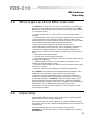
BSS Crossovers
Unpacking
5.0
What is special about BSS Crossovers?
The FDS-310 is a condensation of over ten years experience, manufacturing
the industry's most advanced active crossovers for worldwide use. The FDS310 contains all the features required for todays sound reinforcement systems
in a compact enclosure:
• It can be configured for 2 2-way channels, or for 3-way single channel
operation.
• Crossover frequencies are easily and precisely adjustable for all applications
including sub-woofers. ANY frequency between 180Hz and 9kHz can be
selected at the turn of a knob. Additional crossover frequencies down to 18Hz
can be selected by activating internal, tamper-free switches.
• Stereo signals can be summed for driving sub-woofers in mono.
• Equalisation suiting 'industry standard' HF CD (Constant Directivity) horn/
driver combinations is factory fitted and can be immediately activated.
• All inputs and outputs are balanced for ease of system installation and
interconnection, without hums and buzzes. Additionally, for each frequency
band:
• A green LED confirms signal present.
• A red LED warns of peak clipping (overdrive).
• A MUTE switch allows each frequency band to be switched in/out as an aid
to diagnosis and setting-up.
• A calibrated LEVEL CONTROL accommodates wide variations in the
sensitivity of adjacent frequency bands.
• A POLARITY switch enables each bands' polarity (or absolute 'phase') to be
reversed (or 'inverted').
• Additional, optional internal settings are confirmed by panel LEDs.
Every FDS-310 is manufactured to the highest professional standards, with a
robust steel case, high quality circuit boards, ICs and high quality
components, to provide reliable performance under the most demanding
conditions of the global sound-reinforcement environment. In common with
all other BSS equipment, the FDS-310 is subject to stringent quality control
procedures throughout the manufacturing process. Components are tested
against demanding acceptance criteria. Each completed unit is tested both by
measurement, and in a listening test carried out by trained audio
professionals. To positively ensure reliability, all units are burnt-in for fifty
hours before being tested.
6.0
Unpacking
As part of BSS' system of quality control, this product is carefully inspected
before packing to ensure flawless appearance.
After unpacking the unit, please inspect for any physical damage and retain
the shipping carton and ALL relevant packing materials for use should the unit
need returning.
In the event that damage has occurred, please notify your dealer
immediately, so that a written claim to cover the damages can be initiated.
See Section 25.
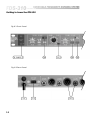
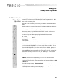
9
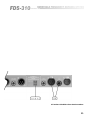
Getting to know the FDS-310
Fig 6.1 Front Panel
Fig 6.2 Rear Panel
10
All numbers in bubbles refer to Section numbers.
11
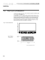
Installation
7.0
Mechanical Installation
A vertical rack space of 1U (1¾" / 44.5 mm high) is required. Ventilation gaps
are unnecessary (See Figure 7.1).
If the FDS-310 is likely to undergo extreme vibration through extensive road
trucking and touring, it is advisable to support the unit at the rear and/or sides
to lessen the stress on the front mounting flange. The necessary support can
generally be bought ready-built as a rack tray. As with any low-level signal
processing electronics, it is best to avoid mounting the unit next to a strong
source of magnetic radiation, for example, a high power amplifier, to help
keep residual noise levels in the system to a minimum.
Fig 7.1 Unit dimensions.
230 mm
(9.06 ins)
482.6 mm
(19 ins)
44 mm
(1.73 ins)
Fig 7.2 Rack
dimensions.
12
Connecting to Power
8.0
Mains Power Connection
Voltage: The FDS-310 operates on either 115 or 230 volt supplies. Use the
voltage selector switch to choose the required voltage setting. (See Figure
8.1).
Frequency: Both 60Hz and 50Hz are acceptable.
Fig 8.1 Mains fuse/
Voltage selector on
rear panel.
Grounding: The FDS-310 must always be connected to a 3-wire grounded
('earthed') AC outlet. The rack framework is assumed to be connected to the
same grounding circuit. The unit must NOT be operated unless the power
cable's ground ('earth') wire is properly terminated - it is important for
personal safety as well as for proper control over the system grounding. To
'lift' the signal ground (0V), refer to section 21.
AC Power fusing: The incoming line passes through an anti-surge ('T') fuse,
accessible from the rear panel. If the fuse blows without good reason, refer to
section 20. Always replace with an identical 20mm x 5mm 'T' fuse, rated at
200mA or 250mA for 230V or 115V settings respectively, for continued
protection from equipment damage and fire.
Power ON: This is indicated by either of the green and yellow LEDs on the
left side of the panel, labelled 'MONO 3-WAY' and 'STEREO 2-WAY'
depending on the mode you have selected. If neither of these LEDs are lit
when the power is connected and the power switch is depressed, refer to
section 20.
13
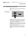
Input Connections
9.0
Input Connections
9.1 Using Jack
Plugs.
Each jack socket accepts signal sources from a 3-pole (stereo), or 2-pole
(mono), 'A' gauge phone plug (See Figure 9.1).
The balanced input of the FDS-310 will accept both balanced or unbalanced
signal feeds, without needing any modification.
There is no internal ground connection to the 'sleeve' on the input jack
socket, to avoid possible interconnection earth loops. The input signal cable
shield must therefore be tied to ground, or signal 0V, at the source end.
Fig 9.1 Phone Jack
Wiring
9.2 Using XLR Plugs.
Each female XLR receptable accepts both balanced and unbalanced signal
sources. For balanced sources, the incoming XLR plug should be connected as
follows (See Figure 9.2):
Pin 1: No connection (it is good practice to terminate the drain wire of
the shield here).
Pin 2: Signal '-', out of phase or 'COLD'.
Pin 3: Signal '+', in phase or 'HOT'.
For unbalanced sources (See figure 9.2):
Pin 1: Leave open, or link to pin 2.
Pin 2: Shield, braid, or screen wire.
Pin 3: Signal '+' or 'HOT' (inner core).
There is no internal ground connection to Pin 1 of the female XLR to avoid
possible interconnection earth loops. The input signal cable shield must
therefore be tied to ground, or signal 0V, at the source end. See section 21 for
help with grounding procedure.
Fig 9.2 XLR Plug Wiring
14
Output Connections
10.0
Output Connections
10.1 Using Phone
Plugs
Each jack socket outputs a balanced signal - symmetrical to ground and
floating. The output is immune from short circuits and drives low impedances
and long cable runs. Each socket accepts either 2-pole or 3-pole (stereo) ¼"
'A' gauge phone plugs. In general, these plugs will automatically provide a
suitable interface with unbalanced and balanced circuits respectively (See
Figure 9.1).
Correct phasing needs attention if the output lines are balanced. For the
majority of balanced line interfaces where the mating jack plugs tip is '+' (or
'hot' or 'in phase'), simply insert the phone plug.
If the FDS-310 output is normally connected via jacks but the input is
connected through an XLR plug, be sure to check XLR polarity. If wired
according to section 8, there will be no problem. If wired with reversed
(European) polarity (Pin 2 'hot', Pin 3 'cold'), the output '+' (hot) will appear
on the phone plugs ring, not tip. In other words, the signal phase or polarity is
transposed when passing through the unit.
The situation can be resolved by swopping around the '+' and '-' connections
to Pins 3 and 2 respectively on the incoming XLR. If in doubt, use a Phasechecker set. If all the surrounding XLR cables are wired Pin 2 '+' ('hot'), you
may find it more convenient to transpose the output sockets polarity. If so,
refer to section 19. If the amplifiers you are feeding have unbalanced (single
ended) inputs, and your system is normally hooked-up with jack plugs, we
recommend you use a standard 2-pole 'A' gauge phone plug, conventionally
wired, as with a guitar lead.
Tip:
To the inner live conductor.
Sleeve:
To the cable shield or screen.
10.2 Using XLR
Plugs
Each male XLR outputs a balanced signal - symmetrical to ground and
floating. The output is immune from short circuits and drives low impedances
and long cable runs. Each output can be interfaced directly with balanced
equipment inputs, down standard 2-core shielded terminated XLRs wired 'pin
to pin' (As Figure 9.2).
Pin 1: Connects to shield, screen or drain wire.
Pin 2: '-', cold or 'out of phase' output.
Pin 3: '+', hot or 'in phase' output.
If the amplifiers you are feeding have unbalanced (single ended) inputs, but
are fed from standard pin to pin XLR cables (see above), simply link the cable
at the crossover end as follows:
Pin 1: Connects to shield or screen wire.
Pin 2: Link to Pin 1.
Pin 3: Connects to the inner 'hot' or live core.
Unbalanced transmission is not recommended for connections to distant
equipment, but is generally acceptable for local connections within the rack
or to an adjacent rack.
Technicians note: As with a traditional transformer balanced output, either
output phase (+ or -, hot or cold) can be linked to ground to 'unbalance the
line' without upsetting the operation of the unit. As with a transformer, output
level remains the same in the unbalanced mode.
15
Setting up 2-Way 2 Channel Operation
11.0
Connection and Setup
11.1 Selecting '2Way' 2 Channel
Operation
In a 2-way system, the incoming full range signal is split into 2 bands.
Normally the corresponding loudspeaker drive units cover Bass (LOW), Top
(HIGH) frequencies, and the crossover point between them lies between
180Hz and 2000Hz (2kHz). When setup for 2-way operation, the FDS-310
handles two channels (stereo). If required, the levels and crossovers points of
each channel can be independantly controlled:
• Release the grey switch on the rear panel 'CROSSOVER MODE
SELECTOR'. Now looking at the front panel left side, check that the green
LED 'STEREO 2-WAY' is lit.
• For single channel operation, insert one input and two output plugs into
'CH.1 MAIN', 'CH.1 LOW' and 'CH.1 HIGH' respectively.
• For dual channel operation, insert two input and four output plugs into the
sockets labelled:
CH.1 MAIN
CH.2 MAIN
INPUTS.
CH.1 LOW
CH.2 LOW
LOW (LF) OUTPUTS.
CH.1 HIGH
CH.2 HIGH
HIGH (HF) OUTPUTS.
For stereo operation, we recommend the following:
CH.1 is designated LEFT Channel.
CH.2 is designated RIGHT Channel.
• To set the crossover point, turn the black knob marked 'CROSSOVER
FREQUENCY Hz' to the desired figure in Hz/kHz. On Channel 2's scale, refer
to the upper, white legend scaled '180-2k0'.
If the FDS-310 has been used previously, check that the red LED marked '10'
next to each frequency knob is unlit. If lit, the 'divide by 10' option needs
disabling - so do not use the crossover until you have read section 11.3.
16
Setting up 3-Way Mono Operation
11.2 Selecting '3Way' Mono
Operation
In a 3-way system, the incoming full range signal is split into 3 bands.
Normally the corresponding loudspeaker drive units cover Bass (LOW), Mid
and Top (HIGH) frequencies. In this mode, the FDS-310 operates in mono and
there are two crossover points.
The LOW-to-MID crossover point normally lies between 180Hz and 2000Hz
(2kHz).
The MID-to-HIGH crossover point normally lies between 800Hz and 9000Hz
(9kHz).
For 3-way operation, follow the yellow legend on the rear panel.
• Depress the grey 'CROSSOVER MODE SELECTOR' switch on the rear
panel. Now check the yellow LED marked 'MONO 3-WAY' on the front
panels left side is lit.
• Insert one input and three output plugs into the following sockets:
CH.1 MAIN
LOW RANGE
INPUTS.
MID RANGE
HIGH RANGE
OUTPUTS.
See sections 9 & 10 for wiring details.
• To set the low-mid crossover point, turn the black knob marked 'LOW-MID'
and 'CROSSOVER FREQUENCY Hz' to the desired figure in Hz/kHz. To set
the mid-high crossover point, turn the black knob marked 'MID-HIGH' and
'CROSSOVER FREQUENCY Hz' to the desired figure in Hz/kHz. Ignore the
white (2-way) scaling and refer only to the yellow legend, scaled 800-9k0.
If the FDS-310 has been used previously, check that the red LED marked '10'
next to each frequency knob is unlit. If lit, the 'divide by 10' option needs
disabling - so do not use the crossover until you have read section 11.3.
ALWAYS check the crossover frequency is set to a safe minimum figure
before driving the system at high levels:
• Set levels controls to their centre zero position, for best sound balance, refer
to section 17.
• For CD Horn equalisation, refer to section 14.
• For sub-woofer (sub-bass) applications, refer to sections 11.3 & 13.
CAUTION: Setting too low a crossover frequency can damage HF drive-units
and/or impair their reliability and sound quality.
17
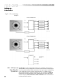
Setting up Schematics
Fig 11.1 2- and 3-Way
Setups
11.3 2-Channel
Sub-Woofer
Operation
18
The FDS-310 can drive sub-woofers ('Sub-Low or 'Sub-Bass' cabinets) when
switched to the 2-way configuration. The Sub-woofer-to-HIGH crossover point
can lie anywhere between 18Hz and 200Hz. The 'high' output is substantially
a full range signal, and is normally split further into 2 or 3 bands, using a
second active crossover. As with conventional 2-way operation, the FDS-310
handles up to 2-channels (stereo) in sub-woofer mode. If a mono sub-woofer
output is required, refer to section 13. Refer to section 22.1 for information on
locating the FREQ switches.
Setting up 2-Channel Sub-Woofer Operation
12.0
Monaural Sub-Woofer Operation for stereo 2-way systems only
Because human hearing is insensitive to the location of low-frequency sound
sources below 100Hz, stereo operation is normally dispensed with when
driving sub-woofers. The FDS-310 contains an internal link which can be set
to sum (mix) the incoming two channel (stereo) signals, so that the two sublow outputs are identical. Meanwhile, full stereo operation is retained on the
'high' outputs. Refer to section 22.2 for information on activating the subwoofers 'MONO mode:
The CH.1 and CH.2 'LOW' outputs will now output an identical sub-woofer
signal. At the same time, the drive levels can be individually adjusted (as
before), using the CH.1 LOW and CH.2 LOW 'LEVEL' controls. This is useful
when the two outputs are used to drive different sub-woofer amplifiers at
different locations, requiring an independent sound balance.
If there is only one sub-woofer, or the sub-woofers absolutely do not require
different drive levels and can therefore be driven from just one of the two
outputs, the unused output serves as a spare.
Fig 12.1 Mono SubWoofer System
13.0
Unusual Crossover Points for 3-way systems only
This is for when a 3-way system requires crossover frequencies outside the
normal range. The internal switches SW2 and SW3 (described in section 11.3)
can be used to extend the range of available crossover points downwards:
• If you require a LOW-to-MID crossover frequency below 180Hz, set SW2
'FREQ' switch to 'divide by 10'. The control will now sweep from 18Hz to
200Hz.
• Setting SW3 to the 'divide by 10' position will produce a sweep from 18Hz
to 200Hz for the MID-to-HIGH crossover frequency. This will only have
limited applications for specialist systems, and care must be taken in its use.
19
Equalising CD Horns
14.0
How to Equalise CD Horns
Todays 'Constant Directivity' (CD) horns and drivers can be used in 2-way
systems with comparatively low crossover frequencies.
Even so, the laws of physics dictate that the very high efficiency attained
cannot be kept up all the way to 20kHz. In addition, the CD horns control of
dispersion further 'thins out' the SPL at higher frequencies. As a result,
response falls off progressively above 4kHz, and more rapidly above 20kHz.
In the FDS-310, optional equalisation has been fitted to compensate for the
effect and provide a more level acoustic response (see Figure 14.1).
When 'STEREO 2-WAY' operation is selected, CD horn equalisation can be
individually setup on both CH.1 and CH.2 HIGH outputs.
When set to 'MONO 3-WAY' mode, the CD horn equalisation can be setup on
the HIGH output (Output 4). The equalisation for output 2, even if selected, is
automatically defeated when in 3-way mode. This means the FDS-310 can be
switched from 2 to 3-way operation with any combination of horn EQ
installed, without complications.
Horn EQ selected
Output status:
2-way Operation
OUTPUT 2
OUTPUT 4
OUTPUT 2 & 4
EQ on CH.1 HIGH only.
EQ on CH.2 HIGH only.
EQ in stereo (CH.1 & CH.2).
3-way Operation
OUTPUT 2
OUTPUT 4
OUTPUT 2 & 4
No EQ.
EQ on 'HIGH RANGE' only.
EQ on 'HIGH RANGE' only
Fig 14.1 CD Horn EQ
Response
Refer to section 22.3 for information on activating the equalisation.
20
Full Range Output
LED Indicators
15.0
Full range Output 3-way operation only
When switched on 'MONO 3-WAY' mode, the Channel 2 input ('FULL
RANGE' in 3-way mode) is not wasted. Instead, it can be used as a balanced
in-out line driver passing through to the adjacent 'FULL RANGE' output
sockets. Follow the yellow legend for this.
In combination with the remainder of the FDS-310, it shares the following
facilities:
• Up to +6dB of gain.
• +6 to -00 gain adjustment, using the 'FULL RANGE' level trim control.
• Balanced or unbalanced drive into load impedances down to 600 ohms.
• Input filtration: -3dB down at 15Hz and 30kHz, see the main specification
in section 24.
Only the crossover filter slopes are disabled in 3-way mode. The 'FULL
RANGE' output retains MUTE and POLARITY switching, and PEAK and
SIGNAL present LED indication, as specified in section 16.
16.0
LED indicators
16.1 'Signal
Present'
On each channel, the LED 'GREEN SIGNAL' lights to show that a signal is
being received. Steady illumination means high drive levels. Periodic flashing
indicates average drive levels. The LEDs will NOT LIGHT if the peak signal
level stays below -15dBu (138 millivolts).
16.2 'Peak'
On each channel, the red 'PEAK' LED lights if the internal signal levels of the
crossover approaches or exceeds overload. They will light at levels in excess
of +17dBu, giving a 3dB advance warning of actual overload and clip which
occurs at +20dBu .
Fig 16.1 Peak and
Signal LEDs
The signal level appearing at the output sockets under these conditions will
depend on the level control position. However, most power amplifiers will be
driven hard into clip at levels in excess of +1dBu. Remember that clipped
output signals are the number one cause of damaged loudspeaker drive-units.
Under all normal conditions, and with a normal system gain-structure, the red
'PEAK' LED will NOT flash - EVER.
If the FDS-310 requires driving so hard that the 'PEAK' LEDs are periodically
lit up, we recommend that you investigate your system's gain structure,
particularly the power amplifiers sensitivity.
21
Crossover Alignment Procedure
17.0
Crossover Alignment Procedure:
Setting the level controls
The modern idea is to set the crossovers' level controls so the entire speaker
system exhibits a uniform, flat response, independent of the rooms' own
acoustic anomalies. This means that powerful T.D.S. (Time-Delay
Spectrometry) equipment is needed to make speedy, reliable measurements.
When room acoustics are less than perfect and the scope for improving the
acoustics is limited, some element of compromise is needed.
A real time analyser (R.T.A.) can be used to aid setting up in conjunction with
pink noise. However, R.T.A is not the complete answer, owing to it's inability
to measure the direct sound field (it cannot altogether ignore the room's
effects). For this reason, fine tuning is always best done by ear.
Using a Real Time Analyser: If the speaker system is concentrated in a single
stack (or several stacks), the direct sound field will generally 'come together'
about 10 to 15 feet on axis to (in line with the centre of) the front of the stack.
This is the optimum location for the analyser's microphone.
• With the FDS-310 switched on and connected, make sure you have set up
the intended crossover frequency (See sections 11.1 & 11.2).
• Set all the level controls on the crossover to the 'Infinity' position (7
o'clock).
• Connect up the R.T.A. The pink noise output drives the system through the
mixer, then the crossover. For now, set the mixers output fader at 'Infinity'
(nil). All EQ controls throughout the sound system should be set to flat. House
EQ (if fitted) should be adjusted later, once the sound systems' basic response
has been made as smooth as possible by adjusting the crossover. The analysers
microphone is positioned on axis to the speaker stack. At this juncture, any
other speaker stacks should be muted (See section 18). If you are setting up a
2-Channel (stereo) system, tune up ONE channel at a time.
• Set all the power amplifiers attenuator (level) controls (where fitted) at
maximum. Alternatively, and more cautiously, you can initially set all
controls at halfway, but only if the amplifiers are identical. Otherwise the
degree of attenuation could vary widely, making it difficult to maintain
balance when the control settings are later increased to yield a better gain
structure.
• Taking the 3-way mode as an example, set the LOW RANGE control on the
crossover at 0dB, then gently raise the mixers output fader until you hear a
moderate level of pink noise rumbling through the low frequency driver(s). A
Sound Pressure Level of around 90 dBSPL C-weighted is optimum, being
enough to swamp the ambient noise level (unless the environment is very
noisy).
• Set the analysers sensitivity control to a suitable level, usually between 90
and 100 dBSPL. Then tweak the pink noise drive level using the mixers' output
fader, until the low frequency read out (typically 100Hz up to your chosen
crossover point) is averaging 0dB (referred to 90dBSPL) on the analysers scale.
• Now slowly turn up the MID RANGE control on the FDS-310 until the
analyser shows the same average output level in the mid band region.
If the pink noise appears higher in pitch and/or seems to be coming from the
mid or high drive-units, turn down immediately, and re-check connections!
22
If the mid output is not enough, even when the crossovers MID RANGE
control is set at maximum (+6dB), check the mid-range power amplifiers
sensitivity. If this cannot be altered, set the MID RANGE control at 0dB, then
decrease the LOW RANGE control, until the two frequency bands fuse
together to give an essentially straight line on the R.T.A display. If the
response appears uneven around the LOW-to-MID crossover frequency, the
drivers polarity may be reversed. Refer to section 24 to remedy this.
• Repeat the procedure again for the HIGH RANGE control. Again, look for
the response around the MID-to-HIGH crossover frequency. If uneven, refer to
section 19. If the high frequency output is not enough, even when the HIGH
RANGE control is set at maximum (+6dB), check the high end amplifier(s).
Since HF drive-units are generally 6 to 12dB more sensitive than mid and low
drive-units, this condition suggests an error in the wiring. When looking for a
'flat' response, do not forget that the crossover cannot correct for the drivers
rolloff at low and high frequencies. Concentrate instead on looking for a flat
response in upper regions of the low drivers frequency range, and the lower
regions of the high end drivers frequency range (Unless Horn EQ is applied,
then refer to section 14). You may wish to repeat the analyser readings with
the microphone placed in a different location. If so, be aware that at locations
of greater than 15 feet or off-axis to the drive-units, the rooms acoustic will
affect the results. In general, the human hearing mechanism will give
preference to the direct sound balance.
Using an SPL meter: If you do not have access to a Real Time Analyser, a
conventional SPL meter can be used instead, provided you have a pink noise
source. In general, tone or sine-wave generators are NOT acceptable in place
of pink noise, unless they produce a pulsed 'warble' effect. Otherwise major
standing-waves can build up, leading to an exaggerated response at spot
frequencies. Like the RTAs microphone, an SPL meter should be mounted on a
microphone stand, on-axis to the speaker stack. Set the meter to read 'C'
weighted (flat). When setting up, measure just one frequency band at once.
This means muting the low frequency band (Using the MUTE switch, see
section 18) before moving on to the mid (or high) frequency band. Then mute
the low and mid, before moving onto the high setting. Overall, your aim is to
ensure that the indicated SPLs of the low, mid and high ranges are the same,
all 90dBCSPL for example. Again, fine tuning should be done by ear.
Using your ears: Many skilled sound engineers will be confident about
adjusting the LOW, MID and HIGH RANGE controls by ear alone. This
method is quick, and here are some tips to enhance accuracy:
• For a system principally intended for music, use a selection of prerecorded
music you know well. You should have a good idea of what it is supposed to
sound like. For a speech only system, there is nothing better than using an
experienced public speaker. If you have to use recorded speech, look out for
comparable dynamics; recordings from FM radio can be heavily compressed.
• If the sound system is principally intended to reproduce recorded music, we
suggest you use quality recordings of vinyl disc on IEC type II chrome (CrO2)
tape.
• If the sound system is principally intended to reproduce live music,
prerecorder music from CDs will provide more representative dynamics. If a
CD player is unavailable, recordings from CDs onto IEC type II chrome (CrO2)
tape are the next best thing.
23
MUTE switch
• All EQ controls throughout the sound system should be set flat before setting
up the FDS-310 LEVEL controls. Any house EQ adjustments can be made
later.
• For a 3-way set up, set the MID RANGE control first for a comfortable level.
Then bring up the LOW RANGE control until the music/vocals/speech is
'filled-out'. Next, increase the HIGH RANGE control until the vocals have a
natural presence. Finally, you may want to readjust the LOW RANGE for the
best balance.
• Where ever possible, note the LEVEL control settings and then challenge
your colleague(s) to repeat the set up, from scratch. Compare your settings,
and try to arrive at a 'best fit' if your ears disagree.
18.0
Using the Mute switch
Each frequency bands' control surface includes a MUTE switch (See Figure
6.1). Depressing it silences the output in question. The associated PEAK and
SIGNAL LEDs remain in operation. Push button muting is an invaluable
facility when setting up, otherwise the LEVEL controls would need to be reset
to -00.
24
POLARITY switch
19.0
Polarity switching and Output Polarity
reversal option
Each frequency bands' control surface includes a POLARITY switch (See
Figure 6.1). Depressing it reverses the polarity ('phasing') of the signal
emerging from the related output socket. It is a valuable 'instant'
troubleshooting aid in complex multi-driver installations.
Polarity in/out relations are factory set, so at any input and any related output:
• XLR + or HOT goes to Pin 3.
• Phone sockets + or HOT goes to tip.
Although wired to 'Pin 3 HOT' convention, this arrangement is perfectly
compatible with XLR Pin 2 systems (to IEC 268 standard), provided input and
output are wired alike (meaning 'Pin for Pin'). This applies to the phone plugs
only. The only problem with operating in 'Pin 2 HOT' mode concerns the
phone plugs, where the 'ring' terminal become the 'HOT' one. If the
remainder of the system is wired 'Pin 2 HOT', you may wish to reverse the
sockets polarity, so the tip becomes the 'HOT' terminal. Refer to section 22.5
for information on reversing polarity.
Aside from loudspeaker drive-unit connections, polarity transposition can arise
in balanced interconnections, if 'HOT' and 'COLD' are swopped on one
(stereo) channel, but not the other. If this has happened, it is more likely to
occur before the crossover. The low frequencies will sound weak and the
stereo image will be thin and distant. If you set up sound reinforcement
systems frequently, a 'phase' or 'polarity' checker set is an invaluable tool for
speedily tracking down any mistakes, and confirming that inter-channel and
inter-band polarity are all correct.
25
Troubleshooting
20.0
26
Troubleshooting
Problem:
Solution:
No Output
Is the MUTE switch depressed?
Is the mains power on? (See section 8).
Check the connections. See Fuse failure (below).
Do you have an input signal?
Is the SIGNAL LED on?
Check the input and output connections (See sections 9 & 10).
Are the power amplifiers switched on?
Problem:
High Frequency signal from 'LOW' output
Low Frequency signal from 'HIGH' output.
Solution:
Switch unit to 3-way operation.
Problem:
Low Frequency signal from CH.1 'HIGH' output
Full range signal from CH.1 'LOW' output.
Solution:
Switch unit to 2-way operation.
Problem:
Sibilant, hissy HF response.
Solution:
Check CD Horn EQ:
If 'EQ IN', check if required.
Problem:
Low signal level on one or two outputs.
Solution:
If the effect depends on the frequency controls setting, view the panel
LEDs to conform the internal 'FREQ' switches are set correctly (See
sections 11.3 - 13).
Then check level control(s) and output wiring.
Problem:
Excessive Hum, Intermittent sound.
Solution:
First check the connections on your input and output plugs (See
sections 9 & 10). Unshielded cables, improperly wired connectors and
damaged cables are the most common cause of sound system hums and
buzzes. Then refer to sections 8 and 21.
Problem:
Solution:
Fuse Failure.
The mains supply fuse is unlikely to blow without an electronic fault
being present (See section 8). If the fuse blows again at switch on or
after a short interval, switch off the unit and arrange for servicing. The
internal DC fuses will only blow in the event of major fault condition. If
they are visibly blown, DO NOT OPERATE THE UNIT. Return it to be
serviced.
Grounding/Earthing
21.0
Grounding/Earthing Procedures
(Curing hums)
The FDS-310 is supplied with the signal ground (0V) tied to chassis, which is
connected in turn to:
• Mains ground (earth).
• Other equipment chassis' in the rack.
If the FDS-310 outputs are connected to amplifiers with unbalanced inputs, it
will normally be necessary to disconnect the internal ground link, to prevent
ground-loop hums. Refer to section 22.4 for information on this procedure:
Since the FDS-310 has balanced inputs and outputs, and because there is no
input ground connection, it is very unlikely that any connection problem will
be experienced, provided the wiring instruction in sections 9 & 10 have been
correctly followed. If the system has a very loud hum and buzzing, we
recommend that you check the input signal leads have their cable shields
properly grounded at the source end (that is at the output socket of the unit
that is connected to the FDS-310s input). If the hum is moderate and slightly
'raspy', we recommend that you check the incoming AC supply is greater
than 90V RMS. Hum can also be induced by radiation from large power
transformers (See section 8).
27
!!! CAUTION - Important Notes !!!
SERVICE SECTION
22.0
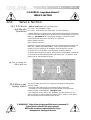
Service Section
22.1 2-Channel
Sub-Woofer
Operation
• Refer to section 11.1, first 3 bulleted points:
For 'LOW', read 'Sub-Bass' Output.
For 'HIGH', read 'Mainly full range signal, for further splitting'.
• Before setting the crossover point, disconnect the mains power, remove the
lid of the unit, and locate the slide switches SW2 and SW3 marked 'divide 10
FREQ X 1' (See Figure 22.1). If sub-woofer operation is required on both
channels, set both switches to 'divide by 10', otherwise:
SW2 activates Channel 1
SW3 activates Channel 2.
Replace the lid and reconnect the power. The red LED marked 'divide by 10'
below the 'CROSSOVER FREQUENCY' knob confirms that the indicated
frequency is now divided by 10. Example: At the knobs fully counterclockwise (7 o'clock) position, now read 18Hz (instead of 180Hz).
To disable the 'divide by 10' option, disconnect the mains power, remove the
lid, and return the slide switch(es) SW2 and SW3 to the 'x 1' position. Then
replace the lid and reinstate the power.
Fig 22.1 Locating the
FREQ switches
22.2 Mono-Low/
Linking switch
This section refers to section 12 in regard to activating the sub-woofers
'MONO' mode:
• Disconnect the mains power and remove the top cover plate.
• Locate the 3-pin programming plug on the left side of the main PCB,
marked 'MONO LOW/LINKING' (See Figure 22.2).
• The jumper is factory fitted in the 'NORMAL' position. Remove it, and
replace it firmly so that it bridges the 'MONO LOW' position. Now replace
the cover plate, and reconnect the mains power.
!!! WARNING - Refer all servicing to qualified service personnel !!!
Risk of electric shock if the unit is opened.
BSS Audio accepts no responsibility for injury
subsequent to opening of the unit.
28
!!! CAUTION - Important Notes !!!
SERVICE SECTION
Fig 22.2 Locating the
MONO LOW/LINKING
switch
22.3 Activating
Equalisation
To activate the equalisation:
• Disconnect the mains power and remove the top cover plate.
• Locate the 3-pin programming plug on the left side of the main PCB,
marked 'CD HORN EQ - OUTPUT 2', and 'CD HORN EQ - OUTPUT 4' in the
centre of the PCB. Refer to the table in section 14 to decide which jumper(s)
will be changed, according to the present operating mode, and your
requirements.
• The jumper is factory fitted in the 'EQ OUT' position. Slide it out and
replace it firmly, so that it bridges the 'EQ IN' position.
• Now replace the cover plate and reconnect the mains power.
Fig 22.3 Locating
the CD HORN EQ
switches
!!! WARNING - Refer all servicing to qualified service personnel !!!
Risk of electric shock if the unit is opened.
BSS Audio accepts no responsibility for injury
subsequent to opening of the unit.
29
!!! CAUTION - Important Notes !!!
SERVICE SECTION
22.4 Eliminating
Hum
• Disconnect the power and remove the top cover plate.
• Locate the green wire bolted to the chassis on the right side of the toroidal
transformer. Check the wire connects to the PCB terminal marked 'CHASSIS'
(See figure 22.4).
• Remove the tag from the chassis bolt, or alternatively unsolder its other end
from the circuit board. Either way, do not leave the wire hanging loose; fold it
over and sleeve for continued safety.
Fig 22.4 Locating the
CHASSIS point
22.5 Polarity
Switching
• Disconnect the power and remove the top cover plate.
• Locate the 1 ohm resistor links behind the phone plug sockets. These are
factory set to position 'A'.
• To reverse the polarity, remove the underside cover-plate, de-solder the
links and replace in position 'B'. The importance of ensuring that all the
drivers in a stack, array or cluster are 'in phase' (meaning they all 'push and
pull' in synchronisation) is well known, although mistakes can occur.
Sometimes, the driver polarity is marked incorrectly on a rogue unit. Most
drive unit manufacturers specify the '+' terminal for the cone moving outward,
but a few hold the opposite convention. If some of the drivers operating within
a specific frequency range in one stack, array or cluster are wired 'out of
phase' with the remainder, the sound output will be partially cancelled.
POLARITY switching at the crossover cannot correct this situation.
If the drivers operating in one frequency range are wired 'out of phase' with
the other frequency band(s), the response at the crossover will exhibit an
audible irregularity, either as a peak or a dip. Use the POLARITY switches to
test this. Depress and release each in turn if you suspect that one frequency
band is wired 'out of phase'. If switching doesn't improve the sound, and the
dip or peak is appreciable, the cause is undoubtedly acoustic, to do with the
drive-unit spacing and path lengths.
!!! WARNING - Refer all servicing to qualified service personnel !!!
Risk of electric shock if the unit is opened.
BSS Audio accepts no responsibility for injury
subsequent to opening of the unit.
30
Glossary
23.0
Glossary
Active
Amplitude
Balanced
Bi-Amped
Crossover Point
dB
Active electronic circuits are those which are capable of voltage and power
gain by using transistors and integrated circuits.
Refers to the voltage level or intensity of a signal, and is usually measured in
voltage or decibels.
A three wire connection in which two of the wires carry the signal
information, and the third acts as a shield tied to chassis ground. The two
signal lines are of opposite polarity at any given moment in time, and are of
equal potential with respect to ground. Balanced connections are used to
improve hum and noise rejection in system interconnections.
Jargon for an active 2-way crossover system.
Jargon for 'Crossover Frequency'
A unit for expressing the ratio between two signal levels for comparison
purposes. On its own it has no absolute level meaning. Rather, it is a
logarithmic ratio used to express the differences between two amounts or
levels. Positive numbers indicate an increase, and negative ones a decrease.
Some useful ratios are:
+3dB
+6dB
+10dB
+20dB
dBm
dBu or dBv
dBV
Distortion
=
=
=
=
Double Power
x 2 Voltage or x 4 Power
x 3 Voltage or x 10 Power
x 10 Voltage or x 110 Power.
The addition of 'm' after dB indicates an absolute scaling for the dB ratio.
Instead of a ratio, the dB becomes a measure of power. 0dBm = a power level
of 1 milliwatt into a load of 600 ohms. It is also loosely used to describe
signal voltage in 600 ohm circuits.
The addition of 'u' or 'v' after dB indicates an absolute scaling for the dB
ratio. 0dBu (or 0dBv) = 778mV or 0.778 Volts, and it has no regard for power
or impedance. This term is widely used for expressing signal voltages in
modern audio equipment with high input impedances and low output
impedances.
The same scale as for dBu as above, except that 0dBV = 1.0 Volts.
Any modification of a signal which produces new frequency components
originally present. Harmonic distortion refers to added frequencies that are
overtones to the fundamental frequency. Intermodulation distortion refers to
added frequencies that are sum and difference values derived from the
beating together of two frequencies.
31
Glossary
Equalisation
Frequency
The repetition of a waveform. The unit of frequency is Hz, and 1 cycle per
second is equal to 1Hz. The audio band is generally restricted to frequencies
of 20Hz to 20,000Hz (20kHz).
Frequency
Response
Equipment's relative gain compared to frequency. Generally expressed as +/a certain number of dBs from 20Hz to 20kHz.
Headroom
The amount, in dBs, above the normal operating level that can be used before
serious distortion commences.
Impedance
The AC equivalent of resistance, measured in ohms. It indicates the amount of
drive required for an input, or the drive capability of an output, at a given
signal level.
Level
The amplitude of a signal, measured in Volts or Decibels.
Line Level
Generally indicates a signal whose level is between -10 and +10dBu or -14 to
+6 dBV. Mic level refers to levels around -40dBu.
Octave
A logarithmic unit for expressing frequency ratios. Positive values indicate an
increase and negative ones a decrease. One octave 'up' the scale is
equivalent to a doubling in frequency. One octave 'down' is equivalent to a
halving of frequency.
Polarity Reversal
An instantaneous change in signal polarity, equivalent to a phase shift of 180
degrees. The same as polarity inversion.
Phase Reversal
Transient
Tri-Amped
Unity Gain
32
Modification of the frequency response of an audio system, regardless of
level, for corrective or enhancement purposes.
Loosely used to describe polarity reversal.
A sudden burst of energy in an audio signal which only lasts for a small period
of time relative to the rest of the signal. The level of these transients can often
reach 10 times (+20dB) or so above the normal operating level of the audio
equipment, and may cause distortion if headroom is inadequate.
Jargon for an active 3-way crossover system.
Where output level is equal to input signal level.
Specifications
24.0
Specifications
Input Impedance:
Balanced bridging; 12k ohms
Max. Input Level:
+20dBm/dBu/dBv
Through Gain:
Input CMRR:
Max. Output Level:
Input to any output with level control set at 0dB: 0dB
Fully adjustable from - to +6dB.
(Common Mode Rejection Ratio)
<-50dB at 120Hz
<-50dB at 10kHz
Balanced Mode:
Unbalanced Mode:
Min. Load Impedance:
Output Impedance:
+26dBv/dBu
15.5v rms
+20dBv/dBu
7.75 v rms
Driven at the MOL, balanced or unbalanced output mode 600 ohms
100 ohms
Frequency Response:
Excluding input filtration, outputs summed with controls set to 0.0dB:
Between 20Hz and 20kHz
+0.5dB
In the midband
+0.2dB
Crossover Filtration:
24dB/OCT (Fourth order) Linkwitz-Riley
Tuneable 2-way:
LOW-HIGH range: 180Hz to 2000Hz (2kHz)
Frequency range is divisible by 10 with internal switching see sections SUB-WOOFER
Tuneable 3-way:
LOW-MID range: 180Hz to 2000Hz (2kHz)
MID-HIGH range: 800Hz to 9000Hz (9kHz)
Input Filtration:
18dB/OCT ultrasonic
6dB/OCT subsonic
-3dB at 30Hz
-3dB at 15Hz
THD Harmonic Distortion:
Including residual noise: <0.03% THD up to MOL
Typically 0.01% at +6dBv/dBu output
Signal-to-noise ratio (SNR):
Controls set at unity (0dB) inputs terminated with 600 ohms
Unweighted: <-85dB, 22Hz to 22kHz
Power requirements:
Less than 30 watts at 95 to 125v AC 50/60Hz
Operating temperature:
5 °C (41 °F) to 55 °C (132 °F)
Mounting requirements:
(Ht x W x D)
44.5mm x 483mm x 216mm
1U/1¾" x 19" x 8.5"
Nett Weight:
Gross Weight:
3.5kg/8lb
(Including carton)
4kg/9lb
33
Warranty Information
25.0
Warranty Information
This unit is warranted by BSS Audio to the original end user purchaser against
defects in workmanship and the materials used in its manufacture for a period
of one year from the date of shipment to the end user.
Faults arising from misuse, unauthorised modifications or accidents are not
covered under this warranty. No other warranty is expressed or implied.
If the unit is faulty it should be sent, in its original packaging, to the supplier
or your local authorised BSS Audio dealer with shipping prepaid.
You should include a statement listing the faults found. The unit’s serial
number must be quoted in all correspondence relating to a claim.
IMPORTANT
We recommend that you record your purchase information here for future
reference.
Dealer Name:
Dealer Address:
Post/Zip Code:
Dealer Phone No.:
Dealer Contact Name:
Invoice/Receipt No.:
Date of Purchase:
Unit Serial Number:
In keeping with our policy of continued improvement, BSS Audio reserves the
right to alter specifications without prior notice.
The FDS-310 was designed and developed by BSS Audio, Hertfordshire,
England.
Phone (+44) (0)1707 660667. Fax (+44) (0)1707 660755.
World Wide Web address: http://www.bss.co.uk
34
Index
Index
Symbols
L
2-Channel Sub-Woofer
Operation. See Setting up
2-Way 2 Channel Operation. See
Setting up
3-Way Mono Operation. See Setting
up
LED indicators
A
Active Crossovers
6
B
Balanced Input. See Input Connections
BSS Crossovers
9
C
Constant Directivity. See Equalising
CD Horns
Contents
3
Crossover Alignment
22
CROSSOVER MODE
SELECTOR. See Setting up
Crossover Points
19
Crossovers
6
E
Equalising CD Horns
20
F
Front Panel
Full range Output
Fuses. See Mains Connection
9
21
G
Getting to know the FDS-310
9
Glossary
31
Grounding. See Mains Connection
Grounding/Earthing
27, 28
I
Input Connections
14
Installation
12
'Invisible' slopes. See Linkwitz-Riley
24
M
Mains Connection
13
Monaural Sub-Woofer Operation 20
Mute switch
27
O
Output Connections
Output Polarity Reversal
15
28
P
Passive Crossovers. See Section 2
Peak. See LED indicators
Polarity switch
28
Power ON. See Mains Connection
R
Rack space. See Installation
Rear Panel. See Getting to know the
FDS-310
Rolloff
7
S
Setting up
16
Signal Present. See LED indicators
Specifications
33
Sub-Low/Sub-Bass. See 2-Channel
Sub-Woofer Operation
Symmetrical radiation patterns. See
Linkwitz-Riley filters
T
Troubleshooting
29
U
Unbalanced Input. See Input Connections
Unit dimensions. See Installation
Using an SPL meter. See Crossover
Alignment
Using R.T.A.. See Crossover Alignment
35
Index
W
Warranty Info.
34
Wiring Convention. See Input
Connections: Output Connections
X
XLR Plugs. See Input Connections
Z
Zero Phase difference. See LinkwitzRiley filters
36
User Notes
37
User Notes
38
User Notes
39
User Notes
40