1
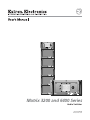
Matrix 3200 and 6400 Series
Audio Switcher
68-355-07 Rev. A
Printed in the USA
Precautions
Safety Instructions • English
This symbol is intended to alert the user of important operating and maintenance
(servicing) instructions in the literature provided with the equipment.
This symbol is intended to alert the user of the presence of uninsulated dangerous
voltage within the product's enclosure that may present a risk of electric shock.
Warning
Power sources • This equipment should be operated only from the power source indicated on the
product. This equipment is intended to be used with a main power system with a grounded
(neutral) conductor. The third (grounding) pin is a safety feature, do not attempt to bypass or
disable it.
Caution
Power disconnection • To remove power from the equipment safely, remove all power cords from
the rear of the equipment, or the desktop power module (if detachable), or from the power
source receptacle (wall plug).
Read Instructions • Read and understand all safety and operating instructions before using the
equipment.
Power cord protection • Power cords should be routed so that they are not likely to be stepped on or
pinched by items placed upon or against them.
Retain Instructions • The safety instructions should be kept for future reference.
Servicing • Refer all servicing to qualified service personnel. There are no user-serviceable parts
inside. To prevent the risk of shock, do not attempt to service this equipment yourself because
opening or removing covers may expose you to dangerous voltage or other hazards.
Follow Warnings • Follow all warnings and instructions marked on the equipment or in the user
information.
Avoid Attachments • Do not use tools or attachments that are not recommended by the equipment
manufacturer because they may be hazardous.
Slots and openings • If the equipment has slots or holes in the enclosure, these are provided to
prevent overheating of sensitive components inside. These openings must never be blocked by
other objects.
Lithium battery • There is a danger of explosion if battery is incorrectly replaced. Replace it only
with the same or equivalent type recommended by the manufacturer. Dispose of used batteries
according to the manufacturer's instructions.
Consignes de Sécurité • Français
Avertissement
Ce symbole sert à avertir l’utilisateur que la documentation fournie avec le matériel
contient des instructions importantes concernant l’exploitation et la maintenance
(réparation).
Alimentations• Ne faire fonctionner ce matériel qu’avec la source d’alimentation indiquée sur
l’appareil. Ce matériel doit être utilisé avec une alimentation principale comportant un fil de
terre (neutre). Le troisième contact (de mise à la terre) constitue un dispositif de sécurité :
n’essayez pas de la contourner ni de la désactiver.
Ce symbole sert à avertir l’utilisateur de la présence dans le boîtier de l’appareil de
tensions dangereuses non isolées posant des risques d’électrocution.
Déconnexion de l’alimentation• Pour mettre le matériel hors tension sans danger, déconnectez tous
les cordons d’alimentation de l’arrière de l’appareil ou du module d’alimentation de bureau (s’il
est amovible) ou encore de la prise secteur.
Attention
Lire les instructions• Prendre connaissance de toutes les consignes de sécurité et d’exploitation avant
d’utiliser le matériel.
Conserver les instructions• Ranger les consignes de sécurité afin de pouvoir les consulter à l’avenir.
Respecter les avertissements • Observer tous les avertissements et consignes marqués sur le matériel ou
présentés dans la documentation utilisateur.
Eviter les pièces de fixation • Ne pas utiliser de pièces de fixation ni d’outils non recommandés par le
fabricant du matériel car cela risquerait de poser certains dangers.
Protection du cordon d’alimentation • Acheminer les cordons d’alimentation de manière à ce que
personne ne risque de marcher dessus et à ce qu’ils ne soient pas écrasés ou pincés par des
objets.
Réparation-maintenance • Faire exécuter toutes les interventions de réparation-maintenance par un
technicien qualifié. Aucun des éléments internes ne peut être réparé par l’utilisateur. Afin
d’éviter tout danger d’électrocution, l’utilisateur ne doit pas essayer de procéder lui-même à ces
opérations car l’ouverture ou le retrait des couvercles risquent de l’exposer à de hautes tensions
et autres dangers.
Fentes et orifices • Si le boîtier de l’appareil comporte des fentes ou des orifices, ceux-ci servent à
empêcher les composants internes sensibles de surchauffer. Ces ouvertures ne doivent jamais
être bloquées par des objets.
Lithium Batterie • Il a danger d'explosion s'll y a remplacment incorrect de la batterie. Remplacer
uniquement avec une batterie du meme type ou d'un ype equivalent recommande par le
constructeur. Mettre au reut les batteries usagees conformement aux instructions du fabricant.
Sicherheitsanleitungen • Deutsch
Vorsicht
Dieses Symbol soll dem Benutzer in der im Lieferumfang enthaltenen
Dokumentation besonders wichtige Hinweise zur Bedienung und Wartung
(Instandhaltung) geben.
Stromquellen • Dieses Gerät sollte nur über die auf dem Produkt angegebene Stromquelle betrieben
werden. Dieses Gerät wurde für eine Verwendung mit einer Hauptstromleitung mit einem
geerdeten (neutralen) Leiter konzipiert. Der dritte Kontakt ist für einen Erdanschluß, und stellt
eine Sicherheitsfunktion dar. Diese sollte nicht umgangen oder außer Betrieb gesetzt werden.
Dieses Symbol soll den Benutzer darauf aufmerksam machen, daß im Inneren des
Gehäuses dieses Produktes gefährliche Spannungen, die nicht isoliert sind und
die einen elektrischen Schock verursachen können, herrschen.
Stromunterbrechung • Um das Gerät auf sichere Weise vom Netz zu trennen, sollten Sie alle
Netzkabel aus der Rückseite des Gerätes, aus der externen Stomversorgung (falls dies möglich
ist) oder aus der Wandsteckdose ziehen.
Achtung
Lesen der Anleitungen • Bevor Sie das Gerät zum ersten Mal verwenden, sollten Sie alle Sicherheits-und
Bedienungsanleitungen genau durchlesen und verstehen.
Aufbewahren der Anleitungen • Die Hinweise zur elektrischen Sicherheit des Produktes sollten Sie
aufbewahren, damit Sie im Bedarfsfall darauf zurückgreifen können.
Befolgen der Warnhinweise • Befolgen Sie alle Warnhinweise und Anleitungen auf dem Gerät oder in
der Benutzerdokumentation.
Keine Zusatzgeräte • Verwenden Sie keine Werkzeuge oder Zusatzgeräte, die nicht ausdrücklich vom
Hersteller empfohlen wurden, da diese eine Gefahrenquelle darstellen können.
Instrucciones de seguridad • Español
Schutz des Netzkabels • Netzkabel sollten stets so verlegt werden, daß sie nicht im Weg liegen und
niemand darauf treten kann oder Objekte darauf- oder unmittelbar dagegengestellt werden
können.
Wartung • Alle Wartungsmaßnahmen sollten nur von qualifiziertem Servicepersonal durchgeführt
werden. Die internen Komponenten des Gerätes sind wartungsfrei. Zur Vermeidung eines
elektrischen Schocks versuchen Sie in keinem Fall, dieses Gerät selbst öffnen, da beim Entfernen
der Abdeckungen die Gefahr eines elektrischen Schlags und/oder andere Gefahren bestehen.
Schlitze und Öffnungen • Wenn das Gerät Schlitze oder Löcher im Gehäuse aufweist, dienen diese
zur Vermeidung einer Überhitzung der empfindlichen Teile im Inneren. Diese Öffnungen dürfen
niemals von anderen Objekten blockiert werden.
Litium-Batterie • Explosionsgefahr, falls die Batterie nicht richtig ersetzt wird. Ersetzen Sie
verbrauchte Batterien nur durch den gleichen oder einen vergleichbaren Batterietyp, der auch
vom Hersteller empfohlen wird. Entsorgen Sie verbrauchte Batterien bitte gemäß den
Herstelleranweisungen.
Advertencia
Este símbolo se utiliza para advertir al usuario sobre instrucciones importantes de
operación y mantenimiento (o cambio de partes) que se desean destacar en el
contenido de la documentación suministrada con los equipos.
Alimentación eléctrica • Este equipo debe conectarse únicamente a la fuente/tipo de alimentación
eléctrica indicada en el mismo. La alimentación eléctrica de este equipo debe provenir de un
sistema de distribución general con conductor neutro a tierra. La tercera pata (puesta a tierra) es
una medida de seguridad, no puentearia ni eliminaria.
Este símbolo se utiliza para advertir al usuario sobre la presencia de elementos con
voltaje peligroso sin protección aislante, que puedan encontrarse dentro de la caja
o alojamiento del producto, y que puedan representar riesgo de electrocución.
Desconexión de alimentación eléctrica • Para desconectar con seguridad la acometida de
alimentación eléctrica al equipo, desenchufar todos los cables de alimentación en el panel trasero
del equipo, o desenchufar el módulo de alimentación (si fuera independiente), o desenchufar el
cable del receptáculo de la pared.
Precaucion
Leer las instrucciones • Leer y analizar todas las instrucciones de operación y seguridad, antes de usar
el equipo.
Conservar las instrucciones • Conservar las instrucciones de seguridad para futura consulta.
Obedecer las advertencias • Todas las advertencias e instrucciones marcadas en el equipo o en la
documentación del usuario, deben ser obedecidas.
Evitar el uso de accesorios • No usar herramientas o accesorios que no sean especificamente
recomendados por el fabricante, ya que podrian implicar riesgos.
Protección del cables de alimentación • Los cables de alimentación eléctrica se deben instalar en
lugares donde no sean pisados ni apretados por objetos que se puedan apoyar sobre ellos.
Reparaciones/mantenimiento • Solicitar siempre los servicios técnicos de personal calificado. En el
interior no hay partes a las que el usuario deba acceder. Para evitar riesgo de electrocución, no
intentar personalmente la reparación/mantenimiento de este equipo, ya que al abrir o extraer las
tapas puede quedar expuesto a voltajes peligrosos u otros riesgos.
Ranuras y aberturas • Si el equipo posee ranuras o orificios en su caja/alojamiento, es para evitar el
sobrecalientamiento de componentes internos sensibles. Estas aberturas nunca se deben obstruir
con otros objetos.
Batería de litio • Existe riesgo de explosión si esta batería se coloca en la posición incorrecta. Cambiar
esta batería únicamente con el mismo tipo (o su equivalente) recomendado por el fabricante.
Desachar las baterías usadas siguiendo las instrucciones del fabricante.
Quick Start — Matrix 3200/6400 Series
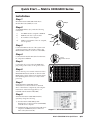
Installation
Step 1
BME
Mount the Matrix 3200/6400 Audio Basic
Module Enclosure (BME) in a rack.
ADD
RES
Step 2
S
Set the BME address (0-5), with the following
restrictions:
IN
INPU
TS
IN
IN
IN
Step 4
IN
IN
IN
OU
T
IN
BME COMM.
Address assignments of 0-5 are accepted,
6-9 are ignored.
IN
OUT
AC
FU POWE
SE
: 250 R INP
UT
V
5.0
A TT
0.5A MAX 50/60Hz
d)
S
AN
AH
MA EIM
DE ,
IN CA
US
A
OUT
PU
TS
OUT
OUT
OUT
OUT
OUT
1-
8
9-
16
Step 3
17
- 24
25
- 32
33
- 40
41
- 48
49
- 56
57
Step 5
Step 3
OUT
OUT
DISCONNECT POWER CORD BEFORE SERVICING
No numbers can be skipped.
ES
E
100-240V
c)
DR
MKP COMM.
B
BME #0 cannot be a Sync module.
4
AD
E
A
b)
E
B
D
D
One BME must be assigned as BME #0.
BM
A
C
C
a)
Step 2
4
- 64
1-
8
9-
16
17
- 24
25
- 32
33
Connect the BME to the rest of the system with
an interconnecting cable (an RJ-11 cable to the
BME COMM connector on the rear of the BME).
- 40
41
- 48
49
- 56
Step 4
AC POWER INPUT
FUSE: 250V 5.0A TT
100-240V
5.0A MAX 50/60Hz
Connect the RS-232/RS-422 cable from the Host
PC computer to BME #0.
Step 5
Connect the AC power cord to the BME, then
plug in the power cord to an AC power source.
DISCONNECT POWER CORD BEFORE SERVICING
57
- 64
Step 6
AC Power Switch
INPUTS
BME
OUTPUTS
-
4
+
ADDRESS
A
IN
IN
IN
IN
IN
IN
IN
IN
OUT
OUT
OUT
OUT
OUT
OUT
OUT
OUT
B
D
E
A
Step 6
C
D
ANAHEIM, CA
MADE IN USA
IN
OUT
BME COMM.
RS232/RS422
E
100-240V
5.0A MAX 50/60Hz
AC POWER INPUT
FUSE: 250V 5.0A TT
DISCONNECT POWER CORD BEFORE SERVICING
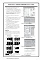
Turn on the AC power switch on the back of the
BME (BME #0 must be turned on after the other
BMEs in the system). Observe the System Status
LED (blinking, then solid on) to verify normal
power-up.
B
MKP COMM.
C
1-8
9 - 16
17 - 24
25 - 32
33 - 40
41 - 48
49 - 56
57 - 64
1-8
9 - 16
17 - 24
25 - 32
33 - 40
41 - 48
49 - 56
57 - 64
Step 7
Install the Matrix 3200/6400 System
Virtualization/Control Software on the hard
drive of the Host PC computer by following the
instructions on the first floppy disk (1 of 2
included with the Matrix 3200/6400).
Step 8
Virtualize the Matrix 3200/6400 Switcher/
System by doing the following:
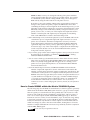
1) Start the Matrix 3200/6400 System
Virtualization/Control Software (MTRX6400)
on the Host PC computer.
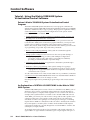
2) Establish RS-232 connection between Host PC
computer and BME #0 (select Comm Port
when asked, then click OK).
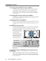
Step 8-2 — Select the Comm Port
Matrix 3200/6400 Series Quick Start
QS-1
Quick Start — Matrix 3200/6400 Series, cont’d
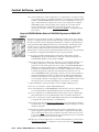
3) Review the program’s Main screen to see
current configuration and settings.
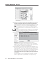
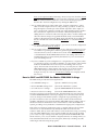
4) Click System-Config to view the Virtual Map
of the system, then select Configure>Physical
Switchers to view a Physical Configuration of
the system. Examine this screen to ensure that
all BMEs are seen and their type and size is
being accurately depicted.
5) Click Close to return to the Virtual Map
screen.
Step 8-3 — Main screen
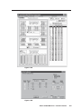
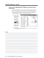
6) Click Configure>Virtual Switcher to program
desired configuration/changes as necessary.
7) Click OK to save changes and return to the
Virtual Map screen.
8) Click Configure>Room Configuration to
create Rooms, or groups of logically
associated virtual outputs.
Step 8-4 — Physical Switchers
9) Click OK to save your changes, then click
Close to return to the Virtual Map screen.
Click Return to Main to return to the Main
Menu, then File>Exit to leave the program.
See Chapter 3 for complete instructions.
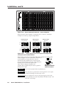
Step 9
Cable the switcher for audio input and output.
Each input/output has a 3.5 mm, 5-pole (stereo
models) or 3-pole (mono models) captive screw
connector for audio.
Balanced Input
Balanced Input
(high impedance)
(600 ohms)
Step 8-5 — Virtual Map screen
600 ohms
R
AUDIO
Tip
Ring
Sleeve (s)
Tip
Ring
L
R
AUDIO
L
Tip
Ring
Sleeve (s)
Tip
Ring
600 ohms
Balanced Output
Balanced Output
Tip
Ring
Sleeve (s)
Tip
Ring
Tip
Ring
Sleeve (s)
Tip
Ring
Unbalanced Input
Mono Input
(high impedance)
R
Tip
Sleeve
AUDIO
L
Tip
Sleeve
Unbalanced Output
Tip
See caution
Sleeve
Tip
See caution
Tip
Ring
Sleeve
Step 8-6 — Virtual Switcher
Mono Output
Tip
Ring
Sleeve
CAUTION Connect the sleeve to ground (Gnd).
Connecting the sleeve to a negative (-) terminal will
damage the audio output circuits.
Matrix 3200/6400 Series Quick Start
Step 8-8 — ROOM Mapper
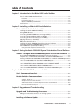
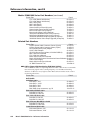
Table of Contents
Chapter 1 - Introduction to the Matrix 6400 Audio Switcher
What is a Matrix 6400 Audio Switcher? ........................................................................... 1-2
Features ............................................................................................................................... 1-2
Feature Descriptions ........................................................................................................... 1-3
Matrix 3200/6400 System Manuals ..................................................................................... 1-4
Specifications ..................................................................................................................... 1-4
Chapter 2 - Installing the Matrix 6400 Audio Switcher
Matrix 6400 Audio Switcher Installation ................................................................... 2-2
Installing the Matrix 6400 Audio BME(s) .......................................................................... 2-2
Setting BME Addresses ...................................................................................................... 2-3
Connecting the BME COMM Interconnecting Cable(s) .................................................... 2-3
Connecting the RS-232/RS-422 Cable to BME #0 .............................................................. 2-4
Connecting the AC Power Cable(s) to the BME(s) ........................................................... 2-4
Applying AC Power to the BME(s) .................................................................................... 2-4
BME Power-Up Verification ............................................................................................... 2-4
Installing the Matrix 3200/6400 Virtualization/Control Software ................................... 2-4
Virtualizing the Matrix 3200/6400 Switcher/System ........................................................ 2-5
Matrix 6400 Audio Input/Output Cabling ........................................................................ 2-5
Using the Audio Captive Screw Connectors ...................................................................... 2-5
Chapter 3 - Using the Matrix 3200/6400 System Virtualization/Control Software
Tutorial - Using the Matrix 3200/6400 System Virt./Control Software ... 3-2
Extron’s Matrix 3200/6400 System Virtualization/Control Program ................................ 3-2
An Explanation of VIRTUAL I/O SWITCHING in the Matrix 3200/6400 System ............... 3-2
Creating a VIRTUAL I/O SWITCHING SYSTEM (MAP) for the Matrix 3200/6400 System . 3-3
How to Create ROOMS within the Matrix 3200/6400 System ......................................... 3-7
How to Remotely CONTROL and PROGRAM the Matrix 3200/6400 System ................... 3-9
How to PROGRAM the Matrix 3200/6400 System in EMULATE MODE ......................... 3-10
How to SAVE and RESTORE the Matrix 3200/6400 Settings .......................................... 3-11
How to Create PROGRAM BYTE STRINGS for the Matrix 3200/6400 System ................ 3-12
Chapter 4 - RS-232 / RS-422 Programmer's Guide
Serial Communications Port .......................................................................................... 4-2
Host to Switcher Communications ............................................................................ 4-3
Command/Response Table ................................................................................................. 4-3
Symbol definitions .............................................................................................................. 4-4
Simple Instruction Set Commands ..................................................................................... 4-4
Advanced Instruction Set and Simple Instruction Set Commands ................................... 4-8
Error Codes with Descriptions .......................................................................................... 4-10
Switcher Generated Unsolicited Responses .................................................................... 4-10
Chapter 5 - Upgrades and Troubleshooting
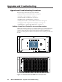
Upgrade and Troubleshooting Procedures ............................................................. 5-2
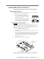
Adding a Front Panel Controller to an existing system ................................................... 5-2
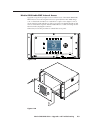
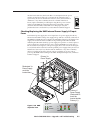
Matrix 6400 Audio BME Internal Access ........................................................................... 5-3
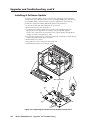
Installing a Software Update ........................................................................................ 5-4
Product Name • Table of Contents
i
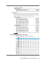
Table of Contents, cont’d
Swapping BME #0 RS-232 / RS-422 Ports ................................................................. 5-5
Ribbon Cable Connectors .................................................................................................. 5-5
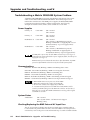
Troubleshooting a Matrix 3200/6400 System Problem .................................... 5-6
Power Supplies ................................................................................................................... 5-6
Communications ................................................................................................................ 5-6
System Status ..................................................................................................................... 5-6
Checking/Replacing the BME External AC Input Fuse ..................................................... 5-6
Checking/Replacing the BME Internal Power Supply AC Input Fuses ............................. 5-7
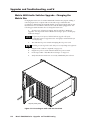
Matrix 6400 Audio Switcher Upgrade - Changing the Matrix Size ............ 5-8
Determining Audio Switcher Circuit Card Population ..................................................... 5-9
Changing the Audio Output Card Gain Jumpers .............................................. 5-10
Adding BME(s) to a Matrix 3200/6400 System ................................................... 5-11
Adding a Matrix 6400 Audio BME .................................................................................. 5-11
Software Procedure - Before and After a Hardware Upgrade .................... 5-12
Upgrade System - Software Procedure ........................................................................... 5-12
Appendix A - Reference Information
Matrix 3200/6400 Series Part Numbers ................................................................... A-2
Binary/Hex/Decimal Conversion Table ..................................................................... A-5
Glossary of Terms .............................................................................................................. A-6
Safety Instructions .................................................................................... Inside Front Cover
Warranty .......................................................................................................... Inside Back Cover
All trademarks mentioned in this manual are the properties of their respective owners.
68-355-07 Rev. A
Printed in the USA
09 02
ii
Matrix 3200/6400 Series • Table of Contents
Matrix 6400 Audio Switcher
1
Chapter One
Introduction to the Matrix 6400
Audio Switcher
What is a Matrix 6400 Audio Switcher?
Features
Specifications
Introduction, cont’d
Introduction
What is a Matrix 6400 Audio Switcher?
The Matrix 6400 Audio Switcher is a 20 Hz to 20 kHz balanced/unbalanced stereo
or mono (depending on the model selected) audio 64x64 switcher housed in a rackmountable metal enclosure with internal universal switching power supply. It may
be used as a stand-alone audio switcher or as part of a Matrix 3200/6400 system
switcher.
In most installations an RS-232 program will be used to control the Matrix 6400
Audio Switcher as a stand-alone switcher or as part of a system switcher. Control
can be from any user-supplied controlling device capable of generating the proper
commands such as a PC using Extron’s Windows® control software or AMX,
Crestron, etc. An optional Front Panel Controller enables the user to perform most
configuration operations at the switcher.
Features
• Virtual input and output assignments
• Independent matrix switching outputs
• 32 Global Preset configurations stored in nonvolatile memory
• 10 Room Configurations with 10 Presets per room
• RS-232/RS-422 (serial port) control
• Rack-mountable, metal enclosure with internal Universal Power Supply
• Optional redundant power supplies
• Optional FPC-1000 Front Panel Controller
• Optional MKP-1000 remote keypads control switching in remote rooms
• 3.5 mm Captive Screw Input and Output Audio connectors
• 25k ohms audio input impedance
• 100 kHz (–3dB) Audio Bandwidth
POWER SUPPLIES
-V
+V
PRIMARY
REDUNDANT
COMMUNICATIONS
RS232
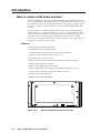
Figure 1-1.A
1-2
BME
SYSTEM
STATUS
REMOTE
TX
RX
DIAGNOSTICS
MATRIX 6400
AUDIO
Matrix 6400 Audio Switcher (front view)
Matrix 3200/6400 Series • Introduction
INPUTS
BME
OUTPUTS
-
4
+
ADDRESS
A
IN
IN
IN
IN
IN
IN
IN
IN
OUT
OUT
OUT
OUT
OUT
OUT
OUT
OUT
B
D
E
A
B
MKP COMM.
C
C
D
ANAHEIM, CA
MADE IN USA
IN
OUT
100-240V
5.0A MAX 50/60Hz
AC POWER INPUT
FUSE: 250V 5.0A TT
DISCONNECT POWER CORD BEFORE SERVICING
BME COMM.
RS232/RS422
E
1-8
9 - 16
17 - 24
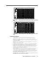
Figure 1-2.A
View)
25 - 32
33 - 40
41 - 48
49 - 56
57 - 64
1-8
9 - 16
17 - 24
25 - 32
33 - 40
41 - 48
49 - 56
57 - 64
Matrix 6400 Audio Switcher (Stereo model - Rear Panel
INPUTS
BME
OUTPUTS
-
4
+
Figure 1-2.B
View)
25 - 32
33 - 40
57 - 64
41 - 48
MONO
MONO
MONO
MONO
OUT
49 - 56
MONO
MONO
MONO
MONO
MONO
MONO
MONO
MONO
MONO
MONO
MONO
MONO
MONO
MONO
MONO
MONO
MONO
MONO
MONO
MONO
33 - 40
OUT
MONO
MONO
MONO
MONO
MONO
MONO
MONO
MONO
MONO
25 - 32
OUT
MONO
MONO
MONO
MONO
MONO
MONO
MONO
MONO
MONO
17 - 24
OUT
MONO
MONO
MONO
MONO
MONO
MONO
MONO
MONO
MONO
MONO
9 - 16
OUT
MONO
MONO
MONO
MONO
MONO
MONO
MONO
MONO
MONO
1-8
OUT
MONO
MONO
OUT
MONO
MONO
MONO
MONO
MONO
MONO
MONO
MONO
MONO
49 - 56
OUT
MONO
MONO
MONO
MONO
MONO
MONO
MONO
MONO
MONO
MONO
MONO
MONO
MONO
41 - 48
IN
MONO
MONO
IN
MONO
MONO
MONO
MONO
MONO
MONO
MONO
MONO
IN
MONO
MONO
MONO
MONO
MONO
MONO
MONO
MONO
17 - 24
MONO
MONO
MONO
MONO
MONO
MONO
MONO
MONO
MONO
MONO
9 - 16
IN
MONO
MONO
MONO
1-8
MONO
MONO
MONO
BME COMM.
100-240V
0.5A MAX 50/60Hz
AC POWER INPUT
FUSE: 250V 5.0A TT
DISCONNECT POWER CORD BEFORE SERVICING
IN
OUT
MONO
RS232/RS422
MONO
ANAHEIM, CA
MADE IN USA
E
MONO
MONO
D
IN
MONO
B
C
IN
MONO
A
IN
MONO
E
MKP COMM.
D
MONO
IN
B
C
MONO
ADDRESS
A
57 - 64
Matrix 6400 Audio Switcher (Mono model - Rear Panel
Feature Descriptions
Virtual Control – Logical assignment of physical Input/Output connector.
Microprocessor Control – A Microprocessor enables the Matrix 6400 Audio
switcher to be programmed from a host system, or from the optional Front Panel
Controller (FPC-1000).
Memory – Nonvolatile memory contents remain valid after power is removed
normally or due to a power failure.
Global Preset configurations (32 +1 ) – Thirty-two Global Preset configurations
plus the current I/O configuration are stored in nonvolatile memory. As new
configurations are developed, they may be stored as Global Presets (up to a total of
thirty-two) in the Preset memory. Any preset may later be recalled – instantly
setting the switcher to the desired configuration.
Room configurations – 10 Room configurations with 10 Presets for each Room
enables 10 different remote locations to control switching for that particular
location using an optional MKP-1000 Remote Keypad. Room Configurations may
be significantly different from room to room and would probably only include a
select number of Inputs and Outputs per room.
RS-232/RS-422 – The Matrix 6400 Audio Switcher can be controlled by any remote
Host system with serial communications capability.
Matrix 3200/6400 Series • Introduction
1-3
Introduction, cont’d
Rack-Mountable metal enclosures – The Matrix 6400 Audio Switcher is housed in
a rack-mountable, metal enclosure (5U high). An internal switch mode power
supply is standard for all models.
Modular Design – The modular design of the Matrix 6400 Audio Switcher allows
users the flexibility to purchase only the modules required.
Optional Redundant Power Supply – If the main power supply fails, the
Redundant Power Supply will take over automatically.
Optional FPC-1000 Front Panel Controller – The FPC-1000 mounts in place of the
blank access panel in the master module (BME #0) and enables the user to perform
most configuration operations at the switcher. See FPC 1000 User’s Manual (Extron
Part #68-355-02).
RGB
MUTE
AUDIO
MUTE
FPC-1000
POWER SUPPLIES
-V
+V
PRIMARY
REDUNDANT
COMMUNICATIONS
RS232
BME
SYSTEM
STATUS
REMOTE
TX
RX
DIAGNOSTICS
MATRIX 6400
AUDIO
Figure 1-3.A
Matrix 6400 Audio Switcher (Front View). Shown with
optional Front Panel Controller (FPC-1000)
Matrix 3200/6400 System Manuals
This manual (68-355-03) covers the Matrix 6400 Audio Switcher. Following is a list
of related manuals:
• 68-355-01 = MKP-1000 User’s manual
• 68-355-02 = FPC-1000 User’s manual
• 68-355-04 = Matrix 3200/6400 Video User’s manual
• 68-355-05 = Matrix 3200 & 6400 Wideband Video/Sync User’s manual
Matrix 6400 Audio Switcher Specifications
Audio — audio BME
Routing .......................................... Up to 64 x 64 (in increments of 8) mono or stereo (depending on model
selected) matrix, balanced/unbalanced
Gain ............................................... Selectable per output...
Unbalanced ............... 0dB (as shipped), or -6dB (jumper-selectable)
Balanced .................... +6dB (as shipped), or 0dB (jumper-selectable)
Frequency response ..................... 20 Hz to 20 kHz, ±0.05dB
THD + Noise ................................ 0.03% @ 20 Hz to 20 kHz, +15dBu input, +21dBu output
S/N ................................................ >85dB, balanced, at rated maximum output drive
Crosstalk ....................................... <-70dB @ 20 Hz to 20 kHz, fully loaded
Stereo channel separation ........... >70dB @ 20 Hz to 20 kHz
CMRR ............................................ >+75dB, 20 Hz to 20 kHz
1-4
Matrix 3200/6400 Series • Introduction
Audio input — audio BME
Number/signal type ................... 8 to 64 (in increments of 8) mono or stereo (depending on model selected),
balanced/unbalanced
Connectors .................................... 8 to 64 3.5 mm captive screw connector, 3 pole (mono) or 5 pole (stereo)
Impedance .................................... >10 kohms unbalanced/balanced, DC coupled
Maximum level ............................ +21.5dBu, (balanced or unbalanced) at stated %THD+N
Input gain adjustment ................. -15dB to +9dB, adjustable per input via RS-232 control or front panel
Audio output — audio BME
Number/signal type ................... Up to 64 (in increments of 8) mono or stereo (depending on model selected),
balanced/unbalanced
Connectors .................................... 3.5 mm captive screw connectors, 3 pole (mono), or 5 pole (stereo) (quantity
varies with configuration)
Impedance .................................... 50 ohms unbalanced, 100 ohms balanced
Gain error ...................................... ±0.1dB channel to channel
Maximum level (Hi-Z) ................ > +26.0dBu, balanced at stated %THD+N
Maximum level (600 ohm) ......... > +24.0dBm, balanced at stated %THD+N
0dBu = 0.775 volts (RMS)
Control/remote — switcher
Serial control port ........................
Baud rate and protocol ...............
Serial control pin configurations ....
System intercommunications ....
Remote keypad control ...............
Program control ...........................
RS-232 or RS-422, 9-pin female D connector
9600, 8-bit, 1 stop bit, no parity
2 = TX, 3 = RX, 5 = GND
2 RJ-11 connectors
2 5 mm, 5-pole captive screw connectors
Extron’s control program for Windows®
Extron’s Simple Instruction Set™ – SIS™
General
Power ............................................. 100VAC to 240VAC, 50/60 Hz; internal, autoswitchable
Matrix 6400 audio ................... 195 watts at 115VAC, 60 Hz
Temperature/humidity .............. Storage -40° to +158°F (-40° to +70°C) / 10% to 90%, non-condensing
Operating +32° to +122°F (0° to +50°C) / 10% to 90%, non-condensing
Rack mount ................................... Yes
Enclosure type .............................. Metal
5U dimensions ............................. 8.75" H x 17.0" W x 14.1" D (5U high, full rack width)
22.2 cm H x 43.2 cm W x 35.8 cm D
(Depth excludes connectors. Width excludes rack ears.)
7U dimensions ............................. 12.25" H x 17.0" W x 14.1" D (7U high, full rack width)
31.1 cm H x 43.2 cm W x 35.8 cm D
(Depth excludes connectors. Width excludes rack ears.)
Shipping/product weight, rack height
Matrix 6400 audio .... 38 lbs (17.2 kg)/28.4 lbs (12.9 kg), 5U
All models: DIM weight ........ 44
Vibration ....................................... ISTA/NSTA 1A in carton (International Safe Transit Association)
Listings .......................................... UL, CUL
Compliances ................................. CE, FCC Class A
MTBF ............................................. 30,000 hours
Warranty ....................................... 3 years parts and labor
Specifications are subject to change without notice.
Matrix 3200/6400 Series • Introduction
1-5
Introduction, cont’d
1-6
Matrix 3200/6400 Series • Introduction
Matrix 6400 Audio Switcher
2
Chapter Two
Installing the Matrix 6400 Audio
Switcher
Installing the Matrix 6400 Audio BME
Installing the Software
BME Cabling
Installation, cont’d
Introduction
Matrix 6400 Audio Switcher Installation
Extron recommends that the following steps be done in the order listed to install a
Matrix 6400 Audio BME.
1.
Installing the Matrix 6400 Audio BME. (Page 2-2)
2.
Set the BME address numbers (0 - 5). (Page 2-3)
3.
Connect the BME COMM interconnecting
cable(s). (Page 2-3)
4.
Connect the RS-232/RS-422 cable to BME
#0’s serial port. (Page 2-3)
5.
Connect the AC Power cable(s) to the
BME(s). (Page 2-3)
6.
Apply AC power to the BMEs and Verify
Normal Power-Up. (Page 2-3)
7.
Load the Matrix 1000 System Virtualization/
Control Software. (Page 2-4)
8.
Virtualize the Matrix 3200/6400 switcher/
system if required. (Page 3-2)
9.
RGB
MUTE
AUDIO
MUTE
FPC-1000
POWER SUPPLIES
-V
+V
PRIMARY
REDUNDANT
COMMUNICATIONS
RS232
BME
REMOTE
SYSTEM
STATUS
TX
MATRIX 6400
RX
AUDIO
DIAGNOSTICS
POWER SUPPLIES
-V
+V
PRIMARY
REDUNDANT
COMMUNICATIONS
RS232
BME
REMOTE
SYSTEM
STATUS
TX
MATRIX 6400
RX
WIDEBAND VIDEO
DIAGNOSTICS
Matrix 6400 Audio Input/Output Cabling.
(Page 2-5)
The numbered procedures that follow match the
steps above.
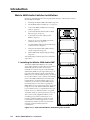
1. Installing the Matrix 6400 Audio BME
POWER SUPPLIES
-V
+V
PRIMARY
REDUNDANT
The Matrix 6400 Audio BME may be a standalone audio switcher or it may be part of a Matrix
6400/3200 System. In either case it may be
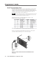
installed in a rack. If it is part of a Matrix 6400/
3200 System, BMEs may be separated by up to 12
feet and rack mounting is NOT required. If the
BMEs are to be rack mounted, they may mounted
in any order within a rack or cabinet. The limiting
factor is the BME COMM interconnecting cable
length which is 12 feet maximum. There are no
restrictions to the order in which BMEs may be
mounted relative to each other. Logically, the
BME addresses in a system such as the one shown
in Figure 2-1.A (with Matrix 6400 Audio BME at
top) would be set to 0 - 5 sequentially from top to
bottom, however, a different order is acceptable
and will not impact system operation in any way.
The location of the equipment within a room
should be given careful consideration. Poor
planning, with the number of cables involved,
could result in a cluttered appearance. Power
requirements and the amount of heat exhaust
from the system should be taken into
consideration.
COMMUNICATIONS
RS232
Matrix 3200/6400 Series • Installation
REMOTE
SYSTEM
STATUS
MATRIX 6400
RX
POWER SUPPLIES
-V
+V
PRIMARY
REDUNDANT
WIDEBAND VIDEO
COMMUNICATIONS
RS232
BME
REMOTE
SYSTEM
STATUS
TX
MATRIX 6400
RX
WIDEBAND VIDEO
DIAGNOSTICS
POWER SUPPLIES
-V
+V
PRIMARY
REDUNDANT
COMMUNICATIONS
RS232
BME
SYSTEM
STATUS
TX
MATRIX 6400
RX
SYNC
DIAGNOSTICS
POWER SUPPLIES
-V
+V
PRIMARY
REDUNDANT
COMMUNICATIONS
RS232
BME
SYSTEM
STATUS
TX
RX
DIAGNOSTICS
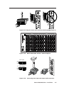
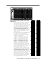
Figure 2-1.A Rack-mounted Matrix 6400/3200 System w/audio
2-2
BME
TX
DIAGNOSTICS
MATRIX 6400
SYNC
The following restrictions apply to installing BMEs:
• One BME must be assigned as BME #0.
• BME #0 cannot be a Sync module.
• Address assignments must not skip numbers.
• Address assignments of 0 - 5 are accepted, BMEs w/address 6-9 are ignored.
• A system is limited to one audio module.
• A system may NOT include both Wideband video and Low Resolution video
modules.
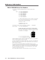
2. Setting BME Addresses
Each BME must be set to a unique address of 0 - 5 using a pushbutton switch
located on the rear panel (see Figure 2-2.B, Item 1). BME #0 will be the Main
Controller and may be any module except the Sync module.
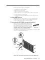
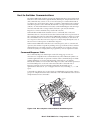
3. Connecting the BME COMM interconnecting cable(s)
If there is more than one BME, the BME COMM connectors
must all be connected together in daisy chain fashion using
Extron supplied RJ-11 telephone cable (Figure 2-2.A). The
chain begins at the BME COMM OUT connector of BME #0
(See Item 2 in Figure 2-2.B) and connects to the BME
Figure 2-2.A
COMM IN connector of the closest BME, that BME’s BME
COMM OUT connector is then connected to the next
closest BME if necessary. Repeat this process until all BMEs are connected (No BME
will have two empty BME COMM connectors).
BME
4
ADD
RES
S
Item 2
6
1
BM
A
E
B
C
4
D
5
AD
E
A
B
C
D
DR
ES
MKP COMM.
9
S
IN
IN
E
INP
UT
IN
AN
MAAHEI
DE M,
IN CA
US
A
S
IN
IN
IN
IN
BME COMM.
T
OU
T
0.5A MAX 50/60Hz
AC
FU PO
SE WER
: 25
0V INPU
5.0 T
A TT
100-240V
Item 4
IN
IN
OU
OU
OU
TP
UT
S
T
OU
T
OU
T
OU
T
OU
T
8
9-
16
17
- 24
25
- 32
33
- 40
41
- 48
49
Item 5
OU
T
OU
1-
Item 3
T
DISCONNECT POWER CORD BEFORE SERVICING
Male
Connector
- 56
57
- 64
1-
8
9-
16
17
- 24
25
- 32
33
- 40
41
- 48
49
- 56
57
- 64
Figure 2-2.B Matrix 6400 Audio Switcher Connections (BME#0 only)
Matrix 3200/6400 Series • Installation
2-3
Installation, cont’d
4. Connecting the RS-232/RS-422 Cable to BME #0
Connect the cable from the Host PC computer serial port to the RS-232/RS-422
connector on the rear panel of BME #0 as shown in Figure 2-2.B below (Item 3).
After the BME(s) have been virtualized, they can be controlled through this
connection using a PC Host or from a touch screen or any other user-supplied
controlling device, such as AMX, Crestron, etc., that is capable of generating the
proper commands.
5. Connecting the AC Power Cable(s) to the BME(s)
Each BME has its own internal power supply. Connect an AC Power cord to the AC
power receptacle on each BME (Item 4 in Figure 2-2.B). Connect the power cord
plug to an AC power source.
6. Applying AC Power to the BME(s)
Each BME has a power ON/OFF toggle switch on the rear panel just above the AC
power cord receptacle. BME #0 must be powered ON at the same time or after all
other BMEs are ON. Press each power switch to the ON (1) position, Go to 6A on
Page 2-4.
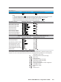
6A. BME Power-Up Verification
The Diagnostics LEDs shown in Figure 2-3.A are located on the front panel of the
Matrix 6400 Audio BME. The normal state of the LEDs after power-up is Primary
+V and -V LEDs ON. If the BME includes a Redundant power supply, the
Redundant +V and -V LEDs
will also be ON. If the Primary
power supply fails, its LEDs
will be OFF and the
Redundant LEDs will blink.
RGB
MUTE
The System Status LED will
initially blink indicating that
internal housekeeping is
occurring, when it goes solid
ON, the system is ready.
AUDIO
MUTE
FPC-1000
POWER SUPPLIES
-V
+V
COMMUNICATIONS
RS232
PRIMARY
TX
REDUNDANT
RX
DIAGNOSTICS
POWER SUPPLIES
-V
+V
COMMUNICATIONS
RS232
PRIMARY
TX
REDUNDANT
RX
BME
REMOTE
BME
SYSTEM
STATUS
REMOTE
MATRIX 6400
AUDIO
SYSTEM
STATUS
DIAGNOSTICS
Figure 2-3.A
7. Installing the Matrix 3200/6400 System Virtualization/ Control Software
The Extron supplied software “Matrix 6400 Series Control Program” runs in the
Windows® operating system, version 3.1 or later. Communication between the
computer software and the switcher requires connecting a PC computer COMM
port to the RS-232/RS-422 Port on the rear panel of module BME #0. Minimum PC
system requirements are:
2-4
Matrix 3200/6400 Series • Installation
486-33 MHz CPU or equivalent with 16 MB RAM
5 MB Hard Disk space for software
If your Matrix 3200/6400 switcher was previously setup for RS-232, and your
PC Comm port uses RS-422, the switcher must be changed to match the PC
interface. The procedure for making the change begins on Page 5-2.
The first floppy disk (1 of 2) has instructions printed on the label. The software
must be installed onto the hard drive. It cannot be run from the floppy disk
1.
Installing the software from the 3.5” floppy disk onto the hard disk is like
most other Windows programs. (Run Setup.exe from the first floppy disk.)
Figure 2-3.B
2.
Installation of the software creates a Program Group (Windows 3.1) or a
Folder (if Windows 95/98 or above) called “Extron Electronics”. Icons for the
Control Program and the Help Program are installed in that group, or folder
(Figure 2-3.B).
3.
Double-click on the “mtrx6400.exe” icon to start the program. You will be
asked to select the Comm Port, or choose “Emulate” mode. After selecting the
COMM port, the software looks for the matrix system, “reads” its
configuration, and then displays it in a window called “Extron’s MATRIX
6400 Control Program”.
Emulate mode allows you to exercise the software without having a switcher
connected to the PC. It may also be used as a learning tool.
8. Virtualizing the Matrix 3200/6400 Switcher/System
Detailed virtualization instructions begin on Page 3-2.
9. Matrix 6400 Audio Input/Output Cabling
Using work-sheets and/or printouts from the Matrix 6400 System Virtualization/
Control Program, install Audio input/output cables as required.
Using the Audio Captive Screw Connectors
The Matrix 6400 Audio Switcher consists of up to 8 input circuit cards and up to 8
output circuit cards. Each card has a single vertical row of 3.5 mm audio receptacles
which support 8 mono or stereo channels (depending on model selected) of input
or output audio (see Figures 2-4.A and 2-5.A). Each audio receptacle has contacts
which are labeled for channel (stereo only), polarity (+/–), and ground. The top
contacts on each circuit card are the lowest input or output number for that
particular slot, for example, input 1 of the input card in slot 1 - 8, input 9 of the card
in slot 9 - 16, etc., or output 1 of the output card in slot 1 - 8, output 9 of the output
card in slot 9 - 16 and so on.
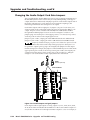
See “Changing the Audio Output Card Gain Jumpers” on Page 5-10.
Captive screw audio connectors (3.5 mm, 5-pole #10-319-10, or 3-pole #10-265-03)
are supplied with each audio switcher, one for each input and one for each output.
The connectors must be wired to the audio cables using the captive screws inside
the connectors (see Figure 2-4.D or 2-5.B). Each captive screw audio connector will
then be plugged into the appropriate input or output position in the rear panel (see
Figure 2-4.B or 2-5.B). See wiring details and cautions that follow on next page.
Matrix 3200/6400 Series • Installation
2-5
Installation, cont’d
INPUTS
BME
OUTPUTS
-
4
+
ADDRESS
A
IN
IN
IN
IN
IN
IN
IN
IN
OUT
OUT
OUT
OUT
OUT
OUT
OUT
OUT
B
D
E
A
B
MKP COMM.
C
C
D
ANAHEIM, CA
MADE IN USA
100-240V
5.0A MAX 50/60Hz
AC POWER INPUT
FUSE: 250V 5.0A TT
DISCONNECT POWER CORD BEFORE SERVICING
IN
OUT
BME COMM.
RS232/RS422
E
1-8
9 - 16
Figure 2-4.A
17 - 24
25 - 32
33 - 40
41 - 48
49 - 56
57 - 64
1-8
9 - 16
17 - 24
25 - 32
33 - 40
41 - 48
49 - 56
57 - 64
Matrix 6400 Audio Switcher - Stereo backplane
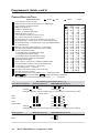
Figure 2-4.B shows three methods of wiring the stereo connectors, with input
examples across the top, output examples below.
Unbalanced Input
Balanced Input
(high impedance)
(high impedance)
Balanced Input
(600 ohms)
600 ohms
R
AUDIO
Tip
Ring
Sleeve (s)
Tip
Ring
L
AUDIO
R
Tip
Ring
Sleeve (s)
Tip
Ring
L
R
Tip
Sleeve
AUDIO
L
Tip
Sleeve
600 ohms
Unbalanced Output
Tip
See caution
Sleeve
Tip
See caution
Balanced Output
Balanced Output
Tip
Ring
Sleeve (s)
Tip
Ring
Tip
Ring
Sleeve (s)
Tip
Ring
Figure 2-4.B
Three ways to wire stereo input and output audio
connectors (see cautions below).
When making connections for the Matrix 6400 Audio switcher from existing audio
cables, see Figure 2-4.C. The round audio connectors are
Tip
Sleeve
shown with the top one (tip and sleeve only) for
Tip (+)
unbalanced audio and the bottom one (tip, ring and
Ring (-)
sleeve) for balanced audio. The "ring", "tip" and "sleeve"
markings are also used on the captive screw
Sleeve
audio connector diagrams in Figure 2-4.C.
Figure 2-4.C
Together, these examples may be used as a guide for
making audio cables.
2-6
Examples of Audio
Cable Connectors
CAUTION
Do not connect equipment that uses phantom power.
CAUTION
Connect the sleeve to ground (Gnd). Connecting the sleeve to a negative
(-) terminal will damage the audio output circuits.
CAUTION
There is no physical way to prevent you from plugging a stereo audio
connector partially in one input and partially in the adjacent input. This
could cause circuit damage.
Matrix 3200/6400 Series • Installation
NO
Tip
Ring
Sleeve
MONO
Tip
Ring
Sleeve
MONO
100-240V
0.5A MAX 50/60Hz
AC POWER INPUT
FUSE: 250V 5.0A TT
1-8
Figure 2-5.A
Figure 2-5.B
9 - 16
MONO
17 - 24
25 - 32
33 - 40
41 - 48
49 - 56
57 - 64
1-8
9 - 16
17 - 24
25 - 32
33 - 40
41 - 48
49 - 56
Matrix 3200/6400 Series • Installation
MONO
MONO
MONO
MONO
MONO
MONO
MONO
MONO
MONO
MONO
MONO
MONO
MONO
MONO
MONO
MONO
MONO
MONO
MONO
MONO
MONO
MONO
MONO
MONO
OUT
MONO
MONO
MONO
MONO
MONO
MONO
MONO
OUT
MONO
MONO
MONO
MONO
MONO
MONO
MONO
OUT
MONO
MONO
MONO
MONO
MONO
MONO
MONO
OUT
MONO
MONO
MONO
MONO
MONO
MONO
MONO
INPUTS
MONO
MONO
MONO
MONO
MONO
MONO
MONO
MONO
OUT
MONO
MONO
MONO
MONO
MONO
MONO
MONO
OUT
MONO
MONO
MONO
MONO
MONO
MONO
MONO
OUT
MONO
MONO
MONO
MONO
MONO
MONO
MONO
MONO
IN
MONO
MONO
MONO
MONO
MONO
MONO
MONO
IN
MONO
MONO
MONO
MONO
MONO
MONO
IN
MONO
MONO
MONO
MONO
MONO
IN
MONO
MONO
MONO
MONO
IN
MONO
MONO
MONO
MONO
BME
MONO
MONO
MONO
IN
MONO
MONO
MONO
IN
MONO
MONO
D
MONO
C
MONO
IN
MONO
ANAHEIM, CA
MADE IN USA
MONO
B
MONO
IN
MONO
C
MONO
OUT
MONO
E
MONO
B
ADDRESS
MONO
A
MKP COMM.
A
MONO
RS232/RS422
E
BME COMM.
D
DISCONNECT POWER CORD BEFORE SERVICING
R
R
L
L
R
R
L
L
IN
IN
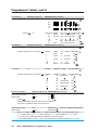
Figure 2-4.D Align the stereo audio connectors before plugging them in.
4
+
-
OUTPUTS
OUT
57 - 64
Matrix 6400 Audio Switcher - Mono backplane
IN
Mono Input
Mono Output
Connecting mono input and output audio connectors
2-7
Installation, cont’d
2-8
Matrix 3200/6400 Series • Installation
Matrix 6400 Audio Switcher
3
Chapter Three
Using the Matrix 3200/6400 System
Virtualization/Control Software
Control Software,
cont’d
Control
Software
Tutorial - Using the Matrix 3200/6400 System
Virtualization/Control Software
Extron’s Matrix 3200/6400 System Virtualization/Control
Program
The Matrix 3200/6400 System Virtualization/Control program communicates
with the Extron Matrix 3200/6400 System through the RS-232/422 port on BME #0
(defaults to 9600 baud, 8 bit, 1 stop, no parity). The program is required to initially
set the Virtualization and optional Room configurations for the system. See the
following two sections for details:
• System Virtualization - creating a virtual I/O switching System - (see Page 3-3)
• Rooming - how to create Rooms - (see Page 3-5)
The program also presents all the functions found on the optional Front-Panel
Controller (FPC 1000), but in an interactive graphical interface, so it may be used
for full control or initial programming of the system. Because settings to the
Matrix (Ties, Presets, Audio config) are stored in the unit’s memory, several modes
of ‘programming’ are possible. It provides 4 major methods:
• Remote control and programming of the system in real time through the
RS-232 port.
• Saving system’s settings for later restoration to the same system (backup) or
copying to (programming) another system. Multiple configurations
(programs) can be saved to disk and any one quickly reloaded later,
providing an unlimited number of possible setups.
• Creating Program byte-strings for application to the Matrix system through a
third-party control system.
• Emulation (off-line) programming of the system’s settings for copying to
system at a later time or another place. Emulation mode also allows creation
of programs for any possible Matrix hardware configuration without being
connected to such a system.
To load a demonstration set of Ties, Presets and Rooms to your Matrix (or Emulate
one) Restore from the DEMO6400.MTX file which was installed with the Windows
Software. Use NEW.INI to clear all settings in a unit.
Note that pressing the F1 key within the program will provide context-sensitive
Help.
An Explanation of VIRTUAL I/O SWITCHING in the Matrix 3200/
6400 System
A Matrix 3200/6400 System consists of from 1 to 6 Switcher boxes (BMEs), each of
which may have as many as 64 inputs and 64 outputs. It is usually desirable to
have certain inputs (or outputs) switch together as a set: to Follow each other. For
example, if the system hardware consisted of a 64 x 64 Video BME and a 64 x 64
Audio BME, you’d want your video monitor’s image and its audio speakers to be
coming from the same source (maybe a VCR) and to follow each other when
switched to another source (perhaps a Laser Disc player). This type of switching
requires the two BMEs to communicate with each other so that they both switch to
the correct inputs to create the follow condition. In the traditional and simplest
configurations, hardware is usually designed to cause both BMEs to switch to the
same input (or output) number.
An example where Follow mode is always required is with S-Video where the ‘Y’
signal and the ‘C’ signal must be switched as a pair of input signals and a pair of
3-2
Matrix 3200/6400 Series • Control Software
output signals. Again, traditional hardware does this by causing the paired signals
to follow each other, either in a single box that is made only for S-Video or by using
two boxes designed for Composite Video and forcing them to follow each other by
switching to the same input (or output) number. Wouldn’t it be nice to have a
single Video switcher box that can be field-programmed to be either an S-video or
Composite Video switcher? This is what Extron’s Virtual I/O Switching does; it
groups physical input connectors and physical output connectors together into
Virtual Inputs and Virtual Outputs, each of which switches from 1 to 6 Virtual Planes.
Let’s carry the S-Video example a step further using the 64 x 64 Video BME and a 64
x 64 Audio BME. If we can map (logically split) the first box into a ‘Y’ plane and a
‘C’ plane and the second box into an ‘Audio’ plane, we will have created a system
with 32 Virtual Inputs and 32 Virtual Outputs in 3 Virtual Planes. [The 32 comes
from splitting the 64 x 64 Video box into two halves]. In this example, half of the
Audio box would not be included in the Virtual map since we only need 32 of the
64 ports and we’d be better off using a 32 x 32 Audio BME for this configuration.
Or, using the same hardware, we could map the first box as ‘Composite Video’ and
the second into an ‘Audio’ plane again to create a system of 64 Virtual Inputs and
64 Virtual Outputs in 2 Virtual Planes. Or, we could map the first box into
‘Component Video’ with a ‘R-Y’ plane, a ‘B-Y’ plane, and a ‘Y’ plane and the
second into an ‘Audio’ plane again to create a system of 21 Virtual Inputs and 21
Virtual Outputs in 4 Virtual Planes. [The 21 comes from splitting the 64 x 64 Video
box into three parts]. All three of these configurations are made with the same two
BMEs merely by loading the appropriate Virtual Map into the Matrix 3200/6400
system’s memory.
Note that the number of Virtual Planes tells you how many physical input (or
output) connectors will be switched together for each Virtual Input (or Output)
switched. In the 21 x 21 x 4 Component Video with Audio virtual system example,
the first BME might have physical inputs 1, 2, and 3 as Virtual Input 1 and 4, 5, and
6 as Virtual Input 2, etc. The Audio BME would have physical input 1 as Virtual
Input 1, 2 as 2, etc.
The Windows Virtualization/Control Program is used to create and load the
Virtual Map to the Matrix 3200/6400 system as described in the Creating a Virtual
I/O Switching System (Map) for the Matrix 3200/6400 System section.
Creating a VIRTUAL I/O SWITCHING SYSTEM (MAP) for the
Matrix 3200/6400 System
The following steps use the Windows Virtualization/Control Program to create a
Virtual I/O Switching System (click here for definitions) within the physical
hardware by generating and loading a map to the Matrix 3200/6400 hardware. A
physical Matrix 3200/6400 System consists of from 1 to 6 Switcher boxes (BMEs),
each of which may have as many as 64 inputs and 64 outputs. After determining
what type and sizes of switcher hardware exists in the matrix, the program will
generate a ‘virtual system’ consisting of from 1 to 64 Virtual Inputs, and 1 to 64
Virtual Outputs, in 1 to 6 Virtual Planes.
• Ensure that all BME’s that will be part of the system have been connected to each
other and their BME numbers have been set correctly. Establish an
RS-232 connection between the PC and BME #0 of the Matrix 3200/6400
System. Start the MTRX6400 program (under Windows) and click on the
corresponding COMM PORT number when asked (Figure 3-2.A). Click OK,
or.....
If you wish to program a system without being connected to it at this time,
click on EMULATE. Follow steps in How to Off-Line (Emulate) Program the
Matrix.
Matrix 3200/6400 Series • Control Software
3-3
Control Software, cont’d
FIGURE 3-2.A
• The program will communicate with the Matrix 3200/6400 System to determine
its hardware configuration (type and size of each connected BME). It then
reads the system’s settings (Ties, Presets, Virtual Map, etc.) and draws a
graphical representation of the unit’s configuration and settings (Ties) on the
Main screen (Figure 3-5.A & B). It also reads the MTRX6400.INI file (saved
from last session) to draw Icons for each I/O (if any had been applied in
previous programming sessions) to make the graphical representation even
more friendly.
If this is a new system that has not been virtualized yet or one that has had its
map cleared, the graphical representation and all information shown on the
Virtual Map screen may be invalid at this time.
• From the menu
on the Main
screen, click
SYSTEMCONFIG to
show the
Virtual Map
screen (see
Figure 34.A). From
the Virtual
FIGURE 3-3.A
Map screen
menu, click CONFIGURE|PHYSICAL SWITCHERS to show the Physical
Configuration screen (Figure 3-3.A). Examine this screen to ensure that all
BMEs were seen and their type and size is being reported as expected. Click
on the ‘Close’ button to return to the Virtual Map screen.
• From the Virtual Map screen menu, click CONFIGURE|VIRTUAL SWITCHER to show
the Virtual Configuration screen. This screen shows how the physical system
will be mapped into a virtual system switcher by the Windows program (see
Figure 3-4.B). You may need to make some choices at this time that affect how
many virtual planes will be created and how many virtual inputs and
outputs will exist. For example, if a Sync BME was found, the program needs
you to decide whether to use composite sync (1 plane) or separate H and V
sync (2 planes).
You need to decide how you want the initial map assignments organized,
whether as ‘Repeat-Pattern’ (e.g. RGBRGB..B) or ‘Group-by-Plane’ (e.g.
3-4
Matrix 3200/6400 Series • Control Software
Figure 3-4.A
Figure 3-4.B
Matrix 3200/6400 Series • Control Software
3-5
Control Software, cont’d
Figure 3-5.A Main Screen - Ties
Figure 3-5.B Main Screen - Presets
3-6
Matrix 3200/6400 Series • Control Software
RRRRGG..BBB). You may also change the ordering of the planes with this
screen and affect which physical connectors get which signals. For example,
in a Wideband system, instead of being in RGB order, you can change it to
BGR order by using the radio buttons in each plane’s choices.
Note that you may play with the settings in this screen without causing any
changes to the system’s map until you press the ‘OK’ button. Even after
committing the changes and viewing them in the Virtual Map screen, you can
still return to this Virtual Configuration screen later and virtualize the system
differently. Changes can be made freely UNTIL you begin to make ties, save
presets, create rooms, or name your virtual inputs and outputs because the
number of virtual inputs and outputs may be changed by re-virtualizing.
Click on the ‘OK’ button to return to the Virtual Map screen.
• In the Virtual Map screen, examine the physical layout of the BMEs and how the
virtualization process assigned the input and output connectors to various
planes. You can return to the Virtual Configuration screen if you wish to
change the mapping at this time by clicking CONFIGURE|VIRTUAL SWITCHER
again. If the map looks correct, you may optionally assign names (up to 12
characters long) to any of the virtual inputs or outputs from the Virtual Map
screen at any time. Names can also be read and edited from the system’s
front panel controller, if present.
• If you wish to group certain virtual outputs together so that you may later create
Room Presets, now would be a good time to Create ROOMS by clicking
CONFIGURE|ROOM CONFIGURATION.
• You can create a hard-copy document that shows all the details from the Virtual
Map screen at any time by clicking the PRINT MAPS menu. The printed maps
make a very handy wiring guide and will appear in color if using a color
printer. You can specify which printer to use from the FILE|SELECT PRINTER
menu in the Main screen.
• From the Virtual Map screen menu, click RETURN TO MAIN and note that the
number of input and output boxes shown on the Main screen matches the
number of virtual input and virtual outputs created by the virtualization. The
virtualization of the system is now complete and the map has been stored in
BME #0. Unless the map gets destroyed or needs to be regenerated because of
a system hardware reconfiguration (size, type, or number of BMEs changes)
or you wish to change the virtual configuration, there is no requirement to
use the Windows Virtualization/Control software. You can, however,
continue to use it to control and program (set Ties, Presets, etc.) the system at
any time.
How to Create ROOMS within the Matrix 3200/6400 System
The following steps use the Windows Virtualization/Control Program to optionally
define Rooms in the Matrix 3200/6400 system. A Room is a group of virtual outputs
that are logically associated with each other, probably by location (such as 3 video
monitors and a VCR all located at a building’s security desk). A Room consists of
from 1 to 16 virtual outputs and the Matrix 3200/6400 supports up to 10 Rooms.
Each Room can have a name (for user friendliness, up to 12 characters long) and up
to 10 Presets assigned to it (for a total of 100 Room Presets). Unlike the 32 Global
Presets, Room Presets only affect those virtual outputs associated with that Room
and do not change any other connections in the Matrix, making the use of Presets
much more simple and flexible. Room Presets are particularly useful in conjunction
with the MKP-1000 keypads.
Rooms exist only to support Room Presets.
Matrix 3200/6400 Series • Control Software
3-7
Control Software, cont’d
• Ensure that the System has
been Virtualized before
creating any Rooms.
Establish an RS-232
connection between the
PC and BME #0 of the
Matrix 3200/6400 System.
Start the MTRX6400
program (under
Windows) and click on the
corresponding COMM PORT
number when asked
(Figure 3-6.A). Click OK,
or......
If you wish to program a
FIGURE 3-6.A
system without being
connected to it at this time, click on EMULATE. Follow steps in How to Off-Line
(Emulate) Program the Matrix.
• The program will communicate with the Matrix 3200/6400 System to determine
its hardware configuration (type and size of each connected BME). It then
reads the system’s settings (Ties, Presets, Virtual Map, etc.) and draws a
graphical representation of the unit’s configuration and settings (Ties) on the
Main screen. It also reads the MTRX6400.INI file (saved from last session) to
draw Icons for each I/O (if any had been applied in previous programming
sessions) to make the graphical representation even more friendly.
• From the menu on the Main screen, click SYSTEM-CONFIG to show the Virtual
Switch Virtual Map screen (Figure 3-4.A). From the Virtual Map screen menu,
click CONFIGURE|ROOM CONFIGURE to show the Room Mapper screen (Figure
3-7.A). Associate a Virtual Output with a room number by using the mouse to
drag the output circle to
the list on the right side.
You can remove a Virtual
Output from a room by
dragging the circle to the
trash-can. You can add a
name to the Room or
edit it by typing in the
text-box. Click on the
‘OK’ button to save your
changes or ‘Cancel’ to
abandon your changes.
Press ‘Close’ to return to
FIGURE 3-7.A
the Virtual Map screen.
• From the Virtual Map screen menu, click RETURN TO MAIN and note that a list-box
for the defined rooms should appear below the ‘Audio Mute’ button. The
Room mapping of the system is now complete and the map is stored in BME
#0. Unless the map gets destroyed or needs to be regenerated because of a
system hardware reconfiguration (size, type, or number of BMEs changes) or
you wish to change the room configuration, there is no requirement to use
the Windows Virtualization/Control software. You can, however, continue to
use it to control and program (set Ties, Presets, etc.) the system at any time.
3-8
Matrix 3200/6400 Series • Control Software
How to Remotely CONTROL and PROGRAM the Matrix 3200/6400
System
Because the Matrix 3200/6400 Switchers store their settings in a nonvolatile
memory, programming applied to the unit from the Virtualization/Control
Program (or the FPC) is remembered in the unit. The Program only needs to talk to
the Matrix system long enough to create (program) the settings. You can, however,
leave a computer connected (dedicated) to the Matrix for real-time interactive
control and monitoring if you wish.
• To control or program the switcher system in real-time, establish an RS-232
connection between the PC and BME #0 of the Matrix 3200/6400 System.
Start the MTRX6400 program (under Windows) and click on the
corresponding COMM PORT number when asked. Click OK, or.....
If you wish to program a system without being connected to it at this time,
click on EMULATE. Follow steps in How to Off-Line (Emulate) Program the
Matrix.
• The program will communicate with the Matrix 3200/6400 System to determine
its hardware configuration (type and size of each connected BME). It then
reads the system’s settings (Ties, Presets, Virtual Map, etc.) and draws a
graphical representation of the unit’s configuration and settings (Ties) on the
Main screen. It also reads the MTRX6400.INI file (saved from last session) to
draw Icons for each I/O (if any had been applied in previous programming
sessions) to make the graphical representation even more friendly.
If this is a new system that has not been virtualized yet or one that has had its
map cleared by a System Reset, the graphical representation and all
information shown on the Virtual Map screen may be invalid at this time.
• Initially, the “Current configuration” from the Matrix is shown. Notice How the
Ties Appear as solid lines in various colors here and How the I/O Ports are
Grouped and Titled. Selecting a Preset (if any exist) from the Presets List at
the right side of the screen will cause that configuration to be read from the
Matrix and drawn on the screen. The displayed preset becomes the “Current
configuration” by clicking the GO BUTTON.
• You can Add and Erase Ties (edit) when in the “Current configuration”. These
edits are made using the mouse in a drag and drop operation. To add a Tie,
drag the input box and drop it on the desired output box (left to right). To
erase a Tie, drag the output box and drop it on the desired input box (right to
left). Note that an output can be rerouted to a different input by merely
adding the new connection (without erasing the old Tie). You can also erase
all Ties that appear on a box by dragging that box to the trash-can. Other
settings will affect how the Tie changes are applied: the Hold/Verify versus
Immediate settings in the Preferences menu. Hold/Verify (the default) shows
Adds and Erases as dotted lines until committed (Take Button) or cancelled
(Cancel Button).
• After you have edited the “Current settings”, you can also store the configuration
as a Preset using the Save As.. Button.
• You can assign a Device icon and a Caption to any of the I/O port boxes for your
convenience in operating the Control Program using the Devices Palette To
access the Devices screen, use the mouse to click on the desired I/O port box
or click the TOOLS|ASSIGN-DEVICE-ICONS menu. Your setting of the Icons are
remembered by the program (NOT by the Matrix) for your convenience in
your next editing session.
Matrix 3200/6400 Series • Control Software
3-9
Control Software, cont’d
• If you have edited any of the configurations or assigned Icons or Captions, when
you exit the program you will be prompted to save the changes. These will be
written to the MTRX6400.INI file for use in your next editing session (if you
agree). The information in the file also allows you to fully restore a Matrix
3200/6400 System to all the settings (Ties, Presets, etc.) from the current
session. We strongly recommend you allow the program to save your
changes! You may also wish to Save the unit’s settings in a uniquely named
file, instead.
How to PROGRAM the Matrix 3200/6400 System in EMULATE
MODE
The Matrix Control Program provides an “Emulate” mode to allow you to build
and save a configuration file, off-line, without being connected to a Matrix System.
This file can later be downloaded (programmed) into a Matrix via the RS-232 port
using the Matrix 3200/6400 Virtualization/Control Program. The Emulate mode
also allows you to generate the RS-232 strings needed to interface a third party
control system to a Matrix System instead of downloading it with the
Virtualization/Control Program. Finally, the Emulate mode allows “programming”
for a hardware configuration that differs from your present system.
• To program a switcher without being connected to it at this time, start the
MTRX6400 program (under Windows) and click on EMULATE (instead of a
COMM PORT number) when asked. Click OK.
• The program will ask for 2 file names. The first is for restoring the settings to an
existing configuration (as though a Matrix with that configuration and
presets were connected). Typical choices for this would be MTRX6400.INI (to
edit the last real-time configuration) or DEMO6400.MTX (to view some
possibilities) or NEW.INI (to start from an empty configuration). This first file
is read by the program (and will not be altered) and is optional: you can
choose CANCEL instead of specifying a name if you wish. The second file is
required and will be created to save the results of editing in the Emulation
mode. It is this file that you would later use for downloading to the Matrix.
You should give this file a meaningful name (i.e. JOB1107.MTX). If the second
file already exists, you’ll be warned that you are about to overwrite it.
• A typical Emulation operation might consist of multiple editing sessions:
• Session A (connected to a Matrix 3200/6400 System)
• Session B (Emulation) use MTRX6400.INI as the first file (source) to edit the last
save from the Matrix use JOB1107.MTX as the second file (destination)
• Session C (Emulation) use JOB1107.MTX as the first file (source) to further edit
the last Emulation save use JOB1107.MTX as the second file (destination)
• Session D (connected to a Matrix 3200/6400 System) Restore from JOB1107.MTX
to program the System from the saved Emulation
• The program will show the Physical Configuration screen using the parameters
read from the source file (if you specified one). Change the settings as needed
and then click TAKE.
• The program reads the emulated settings (Ties, Presets, Virtual Map, etc.) and
draws a graphical representation of the system’s configuration and settings
(Ties) on the Main screen. It also reads the source file to draw Icons for each
I/O (if any had been applied in previous programming sessions) to make the
graphical representation even more friendly.
• Initially, the “Current configuration” from the emulated Matrix is shown. Notice
How the Ties Appear as solid lines in various colors here and How the I/O
3-10
Matrix 3200/6400 Series • Control Software
Ports are Grouped and Titled. Selecting a Preset (if any exist) from the Presets
List at the right side of the screen will cause that configuration to be read
from the emulated Matrix and drawn on the screen. The displayed preset
becomes the “Current configuration” by clicking the GO BUTTON.
• You can Add and Erase ties (edit) when in the “Current configuration”. These
edits are made using the mouse in a drag and drop operation. To add a Tie,
drag the input box and drop it on the desired output box (left to right). To
erase a Tie, drag the output box and drop it on the desired input box (right to
left). Note that an output can be rerouted to a different input by merely
adding the new connection (without erasing the old Tie). Another setting will
affect how the Tie changes are applied: the Hold/Verify versus Immediate
settings in the Preferences menu. Hold/Verify (the default) shows Adds and
Erases as dotted lines until committed (Take Button) or cancelled (Cancel
Button)
• After you have edited the “Current settings”, you can also store the configuration
as a Preset using the Save As.. Button.
• You can assign a Device icon and a Caption to any of the I/O port boxes for your
convenience in operating the Control Program using the Devices Palette. To
access the Devices screen, use the mouse to click on the desired I/O PORT box
or click the TOOLS|ASSIGN-DEVICE-ICONS menu. Your setting of the Icons are
remembered by the program (NOT by the Matrix) for your convenience in
your next editing session.
• If you have edited any of the configurations or assigned Icons or Captions, when
you exit the program you will be prompted to save the changes. These will be
written to the Emulation file for use in your next editing session (if you
agree). The information in the file also allows you to fully restore a Matrix
3200/6400 System to all the settings (Ties, Presets, etc.) from the current
session We strongly recommend you allow the program to save your
changes! You may also wish to Save the unit’s settings in a uniquely named
file, instead.
How to SAVE and RESTORE the Matrix 3200/6400 Settings
The FILE menu provides the following functions:
• Save MATRIX settings as...
(uploads *.MTX file from system)
• Restore MATRIX settings from...
(downloads *.MTX file to system)
• Save This Session’s settings
(uploads MTRX6400.INI file from unit)
• Restore Last Session’s settings
(downloads MTRX6400.INI file to unit)
In normal operation (non-emulation mode), the Virtualization/Control Program
reads the MTRX6400.INI file at start-up to display Icons since these items do not
cause any changes in the Matrix System’s configuration (programming) and
provide convenience to the user. The file actually contains all the information
needed to fully Restore (program) the Matrix 3200/6400 System’s settings. Both of
the Restore functions in the menu cause a FULL Restore of the attached Matrix
System, providing an easy method to switch between (reprogram) configurations.
Both of the Save functions in the menu create a complete .INI type file for future
restoration to an attached Matrix. By default, the SAVE AS choice uses file
extension .MTX, but any name and extension can be used when saving or restoring
a file. The SAVE THIS function is not usually needed since the program prompts
you to create one upon exiting if any edits were performed. The RESTORE LAST
function allows you to set your Matrix configuration back to its settings when you
first started the Virtualization/Control Program (effectively cancelling any edits
and changes without leaving the program).
Matrix 3200/6400 Series • Control Software
3-11
Control Software, cont’d
How to Create PROGRAM BYTE STRINGS for the Matrix 3200/
6400 System
The Matrix 3200/6400 System can be controlled and programmed through the
RS-232 port via third party control systems. These systems need to be “told” what
bytes to send to the Matrix to perform this control. The Matrix 3200/6400 User’s
Manual provides details of how to build these byte strings (using paper and
pencil), but the Matrix Virtualization/Control Program can make this job much
easier by building the strings for you. To generate the strings:
• Create all the Matrix
System settings
(program) from
either Emulate
mode or being
connected to a
Matrix System.
The Program
Strings that can be
viewed produce
the Current-Ties,
Presets, AudioConfig, and RGB
Delay settings.
FIGURE 3-10.A
• To see the strings,
click on the TOOLS|SHOW RS-232-STRINGS menu to show the Program Strings
screen (Figure 3-10.A).
Notes
3-12
Matrix 3200/6400 Series • Control Software
Matrix 6400 Audio Switcher
4
Chapter Four
RS-232/RS-422 Programmer’s Guide
Serial Communications Port
Host-to-Switcher Communications
Command/Response Table
Error Codes
Switcher Initiated Messages
Programmer’s Guide,
cont’d
Programmer’s
Guide
Serial Communications Port
If the Matrix 6400 Audio Switcher is the Master BME (BME #0), its RS-232/RS-422
connector may be connected to the serial port output of a Host device such as a
computer or control panel. Software control of the switcher is made possible by this
connection. A Host serial port connection to the RS-232/RS-422 connector of a
Matrix 6400 Audio Switcher is shown in Figure 4-1.A.
The Matrix 6400 Audio Switcher is normally configured for RS-232 control. If
it is to be used with an RS-422 device, an internal cable must be moved. The
procedure for moving the cable begins on Page 5-2.
The RS-232/422 connector on the Matrix 6400 Audio Switcher is a 9-pin
D female with the following pin assignments:
Pin
1
2
3
4
5
6
7
8
9
RS-232
–
Tx
Rx
–
Gnd
–
–
–
–
Description
not used
Transmit Data
Receive Data
not used
Signal Ground
not used
not used
not used
not used
RS-422
Tx(-)
Tx(+)
Rx(+)
Rx(-)
Gnd
–
–
–
–
Description
Transmit Data (-)
Transmit Data (+)
Receive Data (+)
Receive Data (-)
Ground
not used
not used
not used
not used
The protocol is 9600 baud, 8-bit, 1 stop bit, no parity and no Flow control.
Details for programming the Matrix 6400 Audio Switcher from a Host system
connected to the RS-232/RS-422 port are covered in this chapter.
1
BM
A
6
E
B
C
4
D
AD
E
B
C
D
DR
ES
MKP COMM.
A
S
IN
IN
E
5
INP
UTS
IN
AN
MAAHEIM
DE
IN , CA
US
A
9
IN
IN
IN
IN
IN
IN
BME COMM.
OU
T
OU
0.5A MAX 50/60Hz
OU
UTS
T
OU
T
OU
T
OU
T
8
16
- 24
25
- 32
33
- 40
41
- 48
49
- 56
57
- 64
1-
5
TP
T
OU
17
9
OU
T
OU
9-
1
T
DISCONNECT POWER CORD BEFORE SERVICING
100-240V
OU
1-
6
Female
Connector
T
AC
FU PO
SE WE
: 25 R
0V INPUT
5.0
A TT
8
9-
16
17
- 24
25
- 32
33
- 40
41
- 48
49
Male
Connector
- 56
57
- 64
To Host
System/Device
Serial Port
Figure 4-1.A Matrix 6400 Audio Switcher RS-232/RS-422 to Host
connection
4-2
Matrix 3200/6400 Series • Programmer’s Guide
Host to Switcher Communications
The Matrix 6400 Audio Switcher accepts both Simple Instruction Set and Advanced
Instruction Set Commands through the RS-232/RS-422 port. Simple Instruction Set
(SIS) commands may consist of one or more characters per command field and do
not require any special characters to begin or end the command character sequence.
Switcher responses to SIS commands all end with a carriage return and a line feed
(CR/LF). An Advanced Instruction Set (AIS) command field begins with an Escape
character and ends with a carriage return, line feed is optional (the Switcher
Response to an AIS command always ends with a CR/LF).
When the Matrix 6400 Audio Switcher receives a command (SIS or AIS) and
determines that it is valid, it will execute the command and send a response back to
the controlling (Host) device. If the Matrix 6400 Audio Switcher is unable to execute
the command because it is invalid or contains invalid parameters, it will return an
error response to the Host. The error response is coded to help identify the cause of
the error. Error code responses are defined on Page 4-9.
When a Matrix 6400 Audio Switcher local event takes place, such as a Front Panel
operation, the switcher responds by sending a message to the Host. These switcher
initiated messages are listed on Page 4-9. The switcher does not expect a response
from the host, but, for example, the host program may want to request new status.
Command/Response Table
The Command/Response Table begins on the following page. Lower case
characters are acceptable in the command field only where indicated. Symbols are
used throughout the table to represent variables in the Command/Response fields.
Symbol definitions are shown at the beginning of the table as is an ASCII to
Hexadecimal (HEX) conversion table. Error Response codes and switcher generated
Unsolicited Responses are shown at the end of the table. Command and/or
Response examples are shown throughout the table. Name fields are 12
alphanumeric characters 0 - 9, A - Z (upper and lower case) including “+/-:=” and
space.
Commands are split into two groups which are identified by page headers. The two
groups are “Simple Instruction Set Commands” and “Advanced Instruction Set and
Simple Instruction Set Commands”.
Input
13
C
Input
11
Video Conference
Room
Presentation
Room
Input
14
Training
Room
Input
7-9
Input
10
A
12
D
Media
Room
B
Pl
ay
VC er
R 1
ay
DV er
Pl D 2
ay
VC er
R 3
D
SS
Pl
cs
Extron
Electroni
La
D
ev
ic
e
CO
se
R
ED
r
C
on
M
PA
CO
Q
PC
M
PA
CO
Q
M
PC
PA
Q
PC
G
R
EE
tro
lle
N
r
HO
RI
ZO
NT
AL
VE
RT
IC
AL
AU
DI
O
BL
U
E
Sy
nc
Sy
nc
Input
1-6
Figure 4-2.A Host computer controls Matrix 3200/6400 System
Matrix 3200/6400 Series • Programmer’s Guide
4-3
Programmer’s Guide, cont’d
COMMAND/RESPONSE TABLE
Symbol Definitions:
=
=
=
=
=
=
=
=
=
=
=
=
=
=
=
=
=
=
=
=
=
=
,
= Escape
= CR
= CR/LF
• = space
1 thru maximum number of inputs
Ø thru maximum number of inputs (Input Ø = muted output)
ASCII to HEX Conversion Table
1 thru maximum number of outputs
1B CR ØD LF ØA
· 2Ø
BME number (Ø thru 5)
! 21 “ 22 # 23 $ 24
Ø dB thru 9 dB (audio gain)
% 25 & 26
‘ 27
( 28
1 dB thru 15 dB (audio attenuation)
) 29
* 2A + 2B
, 2C
Numerical Value –15 thru +9
- 2D . 2E / 2F Ø 3Ø
1 thru maximum number of rooms [1Ø max.]
1 31 2 32 3 33 4 34
Ø or 1 (Ø meaning off and 1 meaning on)
5 35 6 36 7 37 8 38
Global preset # (Ø = current ties for system in view) [32 max.]
9 39
: 3A ; 3B < 3C
Room preset # (Ø = current ties for room in view mode) [1Ø max.]
= 3D > 3E ? 3F @ 4Ø
Group Mode (follow). A = All (Follow), B = Aud / Vid / RGB breakaway,
A 41 B 42 C 43 D 44
C = total breakaway
E 45 F 46 G 47 H 48
Delay in ½ second increments [1Ø max. = 5.Ø seconds]
I 49 J 4A K 4B L 4C
M 4D N 4E O 4F P 5Ø
One digit status of Main and Redundant Power Supplies
Q 51 R 52 S 53 T 54
Ø = Off or Dead Power supply
U 55 V 56 W 57 X 58
1 = No Redundant, using Main Power supply
Y 59 Z 5A [ 5B
\ 5C
2 = Using Redundant Power supply
] 5D ^ 5E _ 5F ` 6Ø
3 = Has Redundant, using Main Power supply
a 61 b 62 c 63 d 64
1 through maximum number of virtual planes
e 65
f 66 g 67 h 68
ØØ through 99 (two digits)
i 69
j 6A k 6B
l 6C
(Y)es or (N)o, Y = Mute and N = UnMute for RGB or Audio
m
6D
n
6E
o
6F
p
7Ø
Controller software version to the second decimal place
q
71
r
72
s
73
t
74
Ø = No mute, 1 = Video mute, 2 = Audio mute,
u 75 v 76 w 77 x 78
3 = Video/Audio mute, – = Not used
y 79 z 7A { 7B
| 7C
Two digit Virtual output number [16 per room max]
}
7D
~
7E
DEL
7F
Two digit Virtual input number
Four character physical i/o port (BME# + i or o + port#) example 3iØ7
,
(Virtual Input Name),
(Virtual Output Name) = Maximum
of 12 alphanumeric characters (upper and lower case) “ ” + - : = / and space.
OUTPUT SWITCHING COMMANDS
All
SIMPLE INSTRUCTION SET COMMANDS (PAGE 1 OF 3)
ASCII (HOST-SWITCHER)
RESPONSE (SWITCHER-HOST)
*
!
Out
•In
•All
Example
3*21!
Out21•InØ3
Example explanation: Connect Virtual Output 21 to Virtual Input 3 in all Planes (i.e. Audio
Follows Video).
RGB
*
&
Out
•In
•Vid
Video
*
%
Out
•In
•Vid
Audio
*
$
Out
•In
•Aud
Specific BME
PRESET COMMANDS
*
* !
Out
•In •Bme
Example
11*2*2!
OutØ2•In11•BMEØ2
Example explanation: Connect physical Output 2 in BME 2 to physical Input 11 in BME 2.
ASCII (HOST-SWITCHER)
RESPONSE (SWITCHER-HOST)
Save Current
,
Spr
Recall
.
Rpr
4-4
Matrix 3200/6400 Series • Programmer’s Guide
Save for a room
*
Example
,
Rmm
3*9
•Spr
RmmØ3•SprØ9
Example explanation: Save Current Ties as Preset #9 for Room #3.
Recall for a room
*
RGB MUTE COMMANDS
.
Rmm
ASCII (HOST-SWITCHER)
•Rpr
RESPONSE (SWITCHER-HOST)
RGB Mute
B
Vmt
RGB Un-mute
b
Vmt
Note: Where
is not included, global RGB mute is activated.
SETTING AUDIO GAIN COMMANDS
ASCII (HOST-SWITCHER)
RESPONSE (SWITCHER-HOST)
Positive
Attenuation
*
G
In
•Aud
Example
4*3G
InØ4•Aud+Ø3
Example explanation: Set Audio Gain on Virtual Input 4 to 3 dB.
*
g
In
•Aud
Increment Audio Level (up)
{G
In
•Aud
Decrement Audio Level (down)
}G
In
•Aud
Example
4}G
InØ4•Aud+Ø2
Example explanation: (Decrement Audio Level on Virtual Input 4 - down 1 dB).
AUDIO MUTE COMMANDS
ASCII (HOST-SWITCHER)
RESPONSE (SWITCHER-HOST)
Audio Mute
Z
Amt
Audio Un-mute
z
Amt
LIST COMMANDS
Note: Where
is not included, global Audio mute is activated.
ASCII (HOST-SWITCHER)
RESPONSE (SWITCHER-HOST)
List Room Configuration
LR
ROOM#
Ø1
Ø2
Ø3
NAME
List Virtual inputs
LR
LI
10
,
2
1Ø
Example
3
VIRTUAL OUTPUTS
, 1, 2, 3,
n
, 1, 2, 3,
n
, 1, 2, 3,
n
1
,
,
1
,
2
3
n
ROOM#
Ø1
Ø2
Ø3
Name
VIRTUAL OUTPUTS
Security
, Ø4,11,12,13
Demo Rm
, 27
, 15,16,17,18
Ø9
1Ø
[unassigned]
Conf. Rm
VIRT-IN#
Ø1
Ø2
NAME LVL1 LVL2
, 1 , 2 ,
1
, 1 , 2 ,
2
N
n
,
1
, 31,32
,
2
,
LVL6
6
6
6
Matrix 3200/6400 Series • Programmer’s Guide
4-5
Programmer’s Guide, cont’d
LIST COMMANDS
ASCII (HOST-SWITCHER)
RESPONSE (SWITCHER-HOST)
List Virtual outputs
LO
VIRT-OUT# NAME LVL1 LVL2
Ø1
Ø2
N
Example
LO
2
,
,
n
,
1
1
,
,
1
,
1
LVL6 VMUTAMUT
,
,
,
,
,
,
,
2
6
2
6
,
2
6
VIRT-OUT# NAME
LVL1 LVL2
LVL6 VMUT AMUT
Ø1
Barco7 ,1o16 ,1o17,1o18,2oØ5 ,y,n
Ø2
Preview ,1oØ1 ,1oØ2,1oØ3,2oØ1 ,y,y
LIST COMMANDS
ASCII (HOST-SWITCHER)
2Ø
,1oØ4 ,1oØ5,1oØ6,2oØ2 ,y ,n
21
VCR
,1oØ7 ,1o62,1o63,2o21 ,n ,y
RESPONSE (SWITCHER-HOST)
List Remote Keypad
LK
ADDR#
MODE
ADDR#
1
MODE
GLBL
ID# NAME USER INPUT
,ØØ ,
,Ø1
2
OUTP
,14
,ConfRm1
,Ø5
5
OUTP
,15 , Security2
,Ø5
64
ROOM
,1Ø ,ConfRm2
,Ø1
Example response for LK command
List Presets
LP
Example response for LP command
ID# NAME
NAME
USER INPUT
ROOM#
PRESET#
FOLLOW MODE
ROOM#
GL
PRESET# NAME
FOLLOW MODE
Ø1 ,DailyConfig
,ALL
GL
32
,LunchConfig
,ALL
Ø1
Ø1
,WkEndConfig
,NO
Ø1
Ø2
,NightConfig
,ALL
INFORMATION COMMANDS
1Ø
1Ø
,TestConfig
ASCII (HOST-SWITCHER) RESPONSE (SWITCHER-HOST)
Query Software Version
Specific BME
Q/q
Q/q
,NO
Ver
Ver
Example
4Q
Ver 1.ØØ
Example explanation: Query Firmware version of BME #4.
4Q or 4q is acceptable as ASCII command format.
Request Part Number
Specific BME
N/n
N/n
N6Ø-25x-iofr
N6Ø-25x-iofr
(Response = BME #Ø Part Number)
Note: x = Ø = Matrix 64ØØ Wideband, x = 1 = Matrix 32ØØ Wideband, x = 2 = Matrix 64ØØ Lo Res,
x = 3 = Matrix 32ØØ Lo Res, x = 4 = Matrix 64ØØ Sync, x = 5 = Matrix 32ØØ Sync, x = 6 = Audio.
io = Two character Input/Output Matrix configuration code (see Page B-1)
f = FPC-1ØØØ installed?, Ø = No, 1 = Yes r = Redundant Power Supplies installed?, Ø = No,1 =Yes.
4-6
Matrix 3200/6400 Series • Programmer’s Guide
INFORMATION COMMANDS
ASCII (HOST-SWITCHER)
Request Information
I/i
RESPONSE (SWITCHER-HOST)
I
X
•T
X
Example
I
•Vmt
•U
•Amt
•Sys
•M
•Dgn
I64X64•T1•U2•M21X21•VmtØ•Amt1•Sys1•DgnØØ
Example explanation: I64X64 indicates that this BME has 64 physical inputs and 64 physical outputs.
T1= Wideband Switcher, U2 indicates system has 2 BMEs and is set to M21X21 (21 Virtual Inputs and
21 Virtual Outputs). VmtØ = Video is not Muted, Amt1 = Audio is Muted. Sys1 indicates that this BME
has no redundant power supply and the main power supply is on. DgnØØ indicates no error (BME’s selftest diagnostics passed. Dgn2Ø if reported = System physical size has changed since last virtualized.
Specific BME
I/i
Same as Request Information Response above.
Notes:
1. Command “ØI ” is equivalent to “I” or “i” command.
2.
1 = Wideband, 2 = Lo-Res, 3 = Sync, 4 = Audio (for this BME), Ø = BME not present.
3.
+
is physical size of this BME.
4.
,
,
,
,
are each two digit fields.
ADVANCED INSTRUCTION SET AND SIMPLE INSTRUCTION SET COMMANDS (PAGE 1 OF 3)
ASCII (HOST-SWITCHER)
RESPONSE (SWITCHER-HOST)
VIEW COMMANDS
Audio Gain
V/v
G
In
·Aud
Example
V15G
In15•Aud-Ø6
Example explanation: Virtual Input 15 Audio Level is set to -6 dB.
Global PRESET information
Example
Global PRESET Ties
VI
,Grp
ØVI
Jims_Lecture,GrpA
*
*ØØVA
SO
•
•
SO+1
SO+2
•
•All
SO+15
Views are 16 virtual outputs at a time; each position shows what virtual input is connected to that virtual output.
Preset Ø views the current configuration.
virtual input #4 tied to virtual output #1
Example 1
Ø*Ø1*ØØVA
no virtual input tied to virtual output #16
Ø4•64•ØØ•ØØ•ØØ•ØØ•Ø3•Ø1•ØØ•ØØ•ØØ•64•ØØ•Ø1•ØØ•ØØ•All↵
virtual input #64 tied to virtual output #2
Example 1 explanation: Read Preset Ø (current) Ties of Virtual Inputs to Virtual Outputs Ø1 through 16 in Follow mode.
virtual input #4 tied to virtual output #17
Example 2
no virtual input tied to virtual output #32
Ø4•64•ØØ•ØØ•ØØ•ØØ•Ø3•Ø1•ØØ•ØØ•ØØ•64•ØØ•Ø1•ØØ•ØØ•All↵
Ø*17*ØØVA
virtual input #64 tied to virtual output #18
Example 2 explanation: Read Preset Ø (current) Ties of Virtual Inputs to Virtual Outputs 17 through 32 in Follow mode.
in a 64 virtual input x 56 virtual output configuration,
virtual input #4 tied to virtual output #49 the last 8 virtual outputs are nonexistent (see note 2 below)
Example 3
3*49*ØØVA
Ø4•--•ØØ•ØØ•ØØ•--•Ø3•Ø1•na•na•na•na•na•na•na•na•All↵
virtual output #50 does not have audio follow (see note 3 below)
Example 3 explanation: Read Preset 3 Ties of Virtual Inputs to Virtual Outputs 49 through 64 in Follow mode.
Global PRESET w/Total Breakaway
Command description
Global PRESET by Specific BME
Command description
*
*
VC
SO
•
SO+1
•
SO+2
•
SO+15
•
SO+1
*
*
VD
SO
•
SO+2
•
SO+15
*
VI
Room PRESET Ties
*
*Ø1*ØØVA
Rvo
•
Rvo....
•All
*
*Ø1*
Rvo
•
Rvo....
•Plane
Command description
•Bme
preset*start-output*BME#
Room PRESET information
Room PRESET w/Total Breakaway
•Plane
preset*start-output*plane
,Grp
VC
room*preset*start-output*plane
Matrix 3200/6400 Series • Programmer’s Guide
4-7
Programmer’s Guide, cont’d
Command
1VI
Response
Description
Jims_Lecture,GrpB
Read Preset 1 breakaway information (follow versus breakaway mode)
In the 4 examples below, all Ties are read from a 32 x 32 virtual RGBA (red, green, Blue, Audio) system
with Audio/Video breakaway (Grp B). In Examples 1 and 2 below (Video breakaway), only virtual plane 1
(Red) needs to be read, since virtual planes 2 and 3 (Green and Blue) are the same as virtual plane 1.
Examples 3 and 4 below refer to virtual Audio breakaway with virtual plane 4 representing Audio.
Example 1
1*Ø1*Ø1VC Ø4•64•ØØ•ØØ•ØØ•ØØ•Ø3•Ø1•ØØ•ØØ•ØØ•64•ØØ•Ø1•ØØ•ØØ•Plane 1↵
Explanation: Read Preset 1 Red (plane 1) Ties of Virtual Video Inputs to Virtual Video Outputs Ø1 through 16.
Example 2
1*17*Ø1VC
Ø4•64•ØØ•ØØ•ØØ•ØØ•Ø3•Ø1•ØØ•ØØ•ØØ•64•ØØ•Ø1•ØØ•ØØ•Plane 1↵
Explanation: Read Preset 1 Red (plane 1) Ties of Virtual Video Inputs to Virtual Video Outputs 17 through 32.
Example 3
1*Ø1*Ø4VC
Ø4•64•ØØ•ØØ•ØØ•ØØ•Ø3•Ø1•ØØ•ØØ•ØØ•64•ØØ•Ø1•ØØ•ØØ•Plane 4↵
Explanation: Read Preset 1 Audio (plane 4) Ties of Virtual Audio Inputs to Virtual Audio Outputs Ø1 through 16.
virtual input #4 tied to virtual output #17 no virtual input tied to virtual output #32
Example 4
1*17*Ø4VC Ø4•64•ØØ•ØØ•ØØ•ØØ•Ø3•Ø1•ØØ•ØØ•ØØ•64•ØØ•Ø1•ØØ•ØØ•Plane 4↵
virtual audio plane
virtual input #64 tied to virtual output #18
Explanation: Read Preset 1 Audio (plane 4) Ties of Virtual Audio Inputs to Virtual Audio Outputs 17 through 32.
ADVANCED INSTRUCTION SET AND SIMPLE INSTRUCTION SET COMMANDS
ASCII (HOST-SWITCHER)
RESPONSE (SWITCHER-HOST)
VIEW COMMANDS
Virtual Output MUTES
VM
•
1
•••••
2
Mut
64
Notes:
1. Start output is always Ø1 for Room PRESET, because room has max. of 16 outputs assigned.
2. All “VI” values in responses are 2 numeric characters (i.e. 12 or Ø3) or “na” indicating non-existant virtual
outputs.
3. In “VA” View, any outputs that do not follow show as “- -“ in response.
4. SO = “Start-Output” parameter in “Global Preset commands”.
5. Rvo - Rvo.... = Set of Virtual Outputs assigned to specified “room” (up to 16 total).
RGB DELAY COMMANDS
ASCII (HOST-SWITCHER)
RESPONSE (SWITCHER-HOST)
Read RGB Delay (for 1 ch.)
D
Set RGB Delay (for 1 ch.)
d
*
Out
•Dly
Out
•Dly
Note: Where
= delay in 1/2 second increments (i.e. Ø = Ø sec, 1Ø = 5.Ø sec)
DIRECT WRITE OF
GLOBAL PRESETS COMMANDS
ASCII (HOST-SWITCHER)
RESPONSE (SWITCHER-HOST)
Start Write Mode
End Write Mode
Example
P
p
Write Preset
Ready
End Write Preset
P32
1*1!
1*2&
1*3%
:
:
1*64$
p
Write Preset 32 Ready
End Write Preset 32
Notes:
1. Any non-output switching or invalid command between the Start and End commands will be ignored.
2. If there is no activity for 5 seconds while in write mode, then error E17 occurs.
3. No front panel switching (Actual Switching) is allowed during the Start and End commands.
4. If an End command
p command is issued with no Start command, then error E10 occurs.
4-8
Matrix 3200/6400 Series • Programmer’s Guide
QUICK RECALL OF
GLOBAL PRESETS COMMANDS
Quick Recall Preset
ASCII (HOST-SWITCHER)
.
RESPONSE (SWITCHER-HOST)
Rpr
Notes:
1. If the Quick Recall Preset ( .) command is issued without an active write, then error E10 occurs.
2. Complete backplane switch within 60mSeconds (apprx.) after receipt of the command.
3. Recall must take place 100mSeconds after End Write Mode command ( p ).
4. Quick recall command only recalls last entered direct write preset.
SET NAMES COMMANDS
ASCII (HOST-SWITCHER)
RESPONSE (SWITCHER-HOST)
NG
Read Global preset name
Write Global preset name
nG
,
NamP
Read Room preset name
NP
*
Write Room preset name
nP
* ,
NamP
Read Room Name
NR
Write Room Name
nR
,
NamR
Read Virtual Input Name
NI
Write Virtual Input Name
nI
,
NamI
Read Virtual Output Name
NO
Write Virtual Output Name
nO
,
NamO
ADVANCED INSTRUCTION SET AND SIMPLE INSTRUCTION SET COMMANDS (PAGE 3 OF 3)
ZAP CONFIGURATION COMMANDS
ASCII (HOST-SWITCHER)
RESPONSE (SWITCHER-HOST)
Zap All Global presets & names
Zap individual Global
Zap All Room presets & names
Zap individual Room Preset
Zap All RGB Delay to Ø sec.
Zap all Audio Gains to Ø dB.
UnMute RGB/Audio (All Mutes)
Master Reset
zG
zT
zP
zT
*
zD
zA
zZ
zXXX
ZapG
ZapT
ZapP
ZapT
ZapD
ZapA
ZapZ
ZapXXX
ERROR CODES
If the switcher receives a command that is invalid or contains invalid parameters, it will return an Error Code
response. The error code response has the format “Exx”. Following is a list of possible error code responses.
Description of Error code
EØ1
EØ5
E1Ø
E11
E12
E13
E14
E2Ø
E21
E22
E23
Invalid input channel number (too large)
Device is off
Invalid command
Invalid preset number (too large)
Invalid output number (too large)
Value too large (Gain)
Command not available for matrix configuration
Invalid BME number
Invalid Room number
Busy
Checksum error
Matrix 3200/6400 Series • Programmer’s Guide
4-9
Programmer’s Guide, cont’d
SWITCHER GENERATED UNSOLICITED RESPONSES
When a local event takes place, such as a Front Panel operation, the switcher responds by sending an
unsolicited response (message) to the Host. These switcher initiated messages are listed below.
RECONFIGØØ = Audio level change
RECONFIGØ2 = Room#1 or room#1’s preset name change
RECONFIGØ3 = Room#2 or room#2’s preset name change
RECONFIGØ4 = Room#3 or room#3’s preset name change
RECONFIGØ5 = Room#4 or room#4’s preset name change
RECONFIGØ6 = Room#5 or room#5’s preset name change
RECONFIGØ7 = Room#6 or room#6’s preset name change
RECONFIGØ8 = Room#7 or room#7’s preset name change
RECONFIGØ9 = Room#8 or room#8’s preset name change
RECONFIG1Ø = Room#9 or room#9’s preset name change
RECONFIG11 = Room#1Ø or room#1Ø’s preset name change
RECONFIG12 = Name change for global preset #1-16
RECONFIG13 = Name change for global preset #17-32
RECONFIG14 = Current connection change
RECONFIG17 = Name change for virtual input #1-16
RECONFIG18 = Name change for virtual input #17-32
RECONFIG19 = Name change for virtual input #33-48
RECONFIG2Ø = Name change for virtual input #49-64
RECONFIG21 = Name change for virtual output #1-16
RECONFIG22 = Name change for virtual output #17-32
RECONFIG23 = Name change for virtual output #33-48
RECONFIG24 = Name change for virtual output #49-64
RECONFIG25 = Individual mute change
RECONFIG26 = RGB->SYNC delay change
RECONFIG34 = A global preset has been saved
RECONFIG35 = A room preset has been saved
RECONFIG36 = All RGB Sync Delays initialized (Zapped to Ø sec)
RECONFIG37 = All Audio Levels initialized (Zapped to Ø dB)
RECONFIG38 = All Mutes initialized (Zapped to UnMuted)
RECONFIG4Ø = Global mute change
RECONFIG41 = Power supply status changed
RECONFIG99 = Entire System initialized (Master Reset)
4-10
Matrix 3200/6400 Series • Programmer’s Guide
Matrix 6400 Audio Switcher
5
Chapter Five
Upgrades and Troubleshooting
Upgrade and Troubleshooting Procedures
Installing Software Update (IC Chip)
Swapping RS-232/RS-422 Ports
Changing the AC Fuse
Upgrades and
Troubleshooting,
cont’d
Upgrades
and
Troubleshooting
Upgrade and Troubleshooting Procedures
The following procedures may be done in the field.
• Add Front Panel Controller (FPC-1000) - see Page 5-2.
• Installing a Software Upgrade - see Page 5-4.
• Swapping RS-232 / RS-422 Ports - see Page 5-5.
• Troubleshooting a System Problem - see Page 5-6.
• Adding Audio Cards to a Matrix 6400 Audio Switcher- see Page 5-8.
• Changing the Audio Output Card Gain Jumpers - see Page 5-10.
• Adding BMEs to a Matrix 3200/6400 System - see Page 5-11.
Adding a Front Panel Controller to an existing system
Adding a Front Panel Controller to an existing system involves replacing the blank
Access Panel on any BME (except Sync) with the FPC-1000 panel. A system can
only have one Front Panel Controller and it must be installed on BME #0. The
details for installing the FPC-1000 are included in the User’s Manual provided with
the unit.
RGB
MUTE
AUDIO
MUTE
FPC-1000
POWER SUPPLIES
-V
+V
PRIMARY
REDUNDANT
SYSTEM
STATUS
COMMUNICATIONS
RS232
BME
REMOTE
TX
MATRIX 6400
RX
AUDIO
DIAGNOSTICS
INPUTS
BME
OUTPUTS
-
4
+
ADDRESS
A
IN
IN
IN
IN
IN
IN
IN
IN
OUT
OUT
OUT
OUT
OUT
OUT
OUT
OUT
B
D
E
A
B
MKP COMM.
C
C
D
ANAHEIM, CA
MADE IN USA
100-240V
0.5A MAX 50/60Hz
AC POWER INPUT
FUSE: 250V 5.0A TT
DISCONNECT POWER CORD BEFORE SERVICING
IN
OUT
BME COMM.
RS232/RS422
E
1-8
9 - 16
17 - 24
25 - 32
33 - 40
41 - 48
49 - 56
57 - 64
1-8
9 - 16
17 - 24
25 - 32
33 - 40
41 - 48
49 - 56
57 - 64
Figure 5-1.A Matrix 6400 Audio BME Front and Rear Panels
5-2
Matrix 3200/6400 Series • Upgrades and Troubleshooting
Matrix 6400 Audio BME Internal Access
Upgrades or repairs may require access to internal areas of the Matrix 6400 Audio
BME. This involves removing the front access panel (blank or FPC-1000) using a
coin or a flat blade screwdriver to rotate the two captive screws (Figure 5-2.A) as
shown in Figure 5-2.B. Pull the top of the access panel out slightly then lift up and
remove it from the front panel. The FPC-1000 will have a cable connecting it to the
Main Controller, unplug the connector.
When done, reverse the procedure to reinstall the access panel.
RGB
MUTE
AUDIO
MUTE
FPC-1000
POWER SUPPLIES
-V
+V
PRIMARY
REDUNDANT
COMMUNICATIONS
RS232
BME
SYSTEM
STATUS
REMOTE
TX
RX
DIAGNOSTICS
MATRIX 6400
AUDIO
Figure 5-2.A
RG
MU B
TE
AU
MUDIO
TE
Figure 5-2.B
Matrix 3200/6400 Series • Upgrades and Troubleshooting
5-3
Upgrades and Troubleshooting, cont’d
Installing A Software Update
To install a software update, IC U9 or U6 (or both) on the Main Control printed
circuit card is replaced. If the system consists of multiple BMEs, the software IC(s)
in each BME’s Main Control PCB may need to be updated. Use the following
procedure to replace the Matrix 6400 Audio Main Control PCB IC(s).
1. Power the system OFF and unplug the AC power cord.
2. Remove the Access Panel. See Page 5-3.
3. Use the PLCC IC puller (Figure 5-3.A) to remove the existing Software IC.
Squeeze the tool to align the hooks with the slots provided in opposite
corners of IC socket U9 or U6. Insert the hooks, squeeze gently and pull the IC
straight out of the socket. Set the IC aside.
4. Note the key (angled corner) of the new Software IC. Orient this to match the key
of the socket and carefully press it in place.
5. Reinstall the Access Panel.
6. Plug in the AC power cord, power the system ON.
7. Verify that the switcher is working properly.
19
J1
20
1
2
TION
CAU
GE
HIG
H
VO
LTA
TION
CAU
PO
WE
+V R SU
PPL
-V
GE
IES
HIG
H
VO
LTA
PR
IMA
RY
RE
DU
ND
AN
T
TX
RS
CO
232 MMUN
ICA
BM TIONS
E
RE
RX
DIA
GN
OS
TIC
S
MO
TE
SYS
STATEM
TUS
Main Control Card
MAIN +
J13
RED +
J14
U9
J8
RED J16
J5
J4
J1
U6
MAIN J15
To Diagnostics
LEDs
Figure 5-3.A Updating the Software IC on the Main Control Card
5-4
Matrix 3200/6400 Series • Upgrades and Troubleshooting
Swapping BME #0 RS-232 / RS-422 Ports
Swapping BME #0 RS-232/RS-422 ports (not required on BME #1 - BME #5)
involves moving a ribbon cable from one Main Control card connector to another.
Ribbon Cable Connectors
The ribbon cables used in the Matrix 6400 Audio Switcher use a self-latching style
receptacle. Figure 5-4.A shows how it operates.
1.
Press each of the two tabs outward, this unlocks
the receptacle and ejects the ribbon cable
connector part way. Pull evenly on the ribbon
cable connector to remove it.
2.
When reconnecting the cable, first align the pins
in the receptacle with the holes in the connector
and press evenly into the receptacle until the
receptacle tabs lock the connector in place.
Swapping Serial Ports (RS-232/RS-422)
Before working inside, unplug the power cord.
The Matrix 6400 Audio Switcher is normally connected for RS-232 use. If your
application requires RS-422, follow this procedure (and Figure 5-4.B) to change the
configuration. The procedure for removing and installing the ribbon cables is
described above in “Ribbon Cable Connectors” above.
1.
Power OFF BME #0, unplug the power cord.
2.
Remove the Access Panel on BME #0 (Page 5-3), locate the Main Control card
(see Figure 5-3.A).
3.
Locate ribbon cable receptacles J4 and J5 (Figure 5-4.B). One is empty and the
other has a ribbon cable which goes to the rear panel. The ribbon cable plugs
into J4 for RS-232 and J5 for RS-422. If the connection is wrong for your
application, disconnect the cable and move it to the other receptacle.
4.
Reinstall the Access Panel.
5.
Plug in the AC power cord, power ON the BME.
MAIN +
J13
RED +
J14
U9
RS-422
RED J16
To RS-232/RS-422
Connector
J8
J5
RS-232
MAIN J15
J1
J4
To Diagnostics LEDs
Figure 5-4.B Main Control Card (for card location, see Figure 5-3.A)
Matrix 3200/6400 Series • Upgrades and Troubleshooting
5-5
Upgrades and Troubleshooting, cont’d
Troubleshooting a Matrix 3200/6400 System Problem
All Matrix 3200/6400 BME front panels include LEDs at the bottom of the panel
which are bracketed and labeled DIAGNOSTICS. These LEDs (Figure 5-6.A)
indicate the current status of the BME power supplies, the RS232/BME/MKP1
Communications RX and TX lines, and the System Status. The following
descriptions include normal/failure/status conditions for each LED.
Power Supplies
Primary +V
Green LED
ON = Normal
OFF = Failure
Primary -V
Green LED
ON = Normal
OFF = Failure
Redundant +V
Green LED
ON = Normal
OFF = Failure (or Redundant not present)
Blinking = Redundant +V supplying full +V load
(indicates Primary +V power supply failure)
Redundant -V
Green LED
ON = Normal
OFF = Failure (or Redundant not present)
Blinking = Redundant -V supplying full +V
load (indicates Primary -V power supply failure)
If a BME fails to power ON, check the BME external AC fuse (see Page 5-7).
If the Diagnostic LEDs indicate that a power supply has failed, check the power
supply fuse (see Page 5-7).
BME #0 must be powered ON at the same time or after other BMEs. Any BME
powered on after BME #0 will not be seen by the internal system software.
Communications
RS232 TX - Red LED ON/Blinking = BME is transmitting data to Host
RS232 RX - Green LED ON/Blinking = BME is receiving data from Host
BME TX - Red LED ON/Blinking = BME is transmitting data
BME RX - Green LED ON/Blinking = BME is receiving data
MKP TX - Red LED ON/Blinking = BME is transmitting to Remote keypad
MKP RX - Green LED ON/Blinking = BME is receiving from Remote keypad
1. MKP TX/RX LEDs are not present on SYNC BMEs.
2. MKP LED conditions above apply only to BME #0.
3. RS-232 LED conditions above apply only to BME #0.
4. A communications failure between BME #0 and other BMEs could be
caused by one BME loading down the BME TX or RX line. To determine if
that is the case, run the RJ-11 BME COMM interconnecting cable to bypass
each BME one at a time.
System Status
Amber LED
ON = Normal
OFF = System failure - Call Extron Tech Support
Blinking = Busy
Checking/Replacing the BME External AC Input Fuse
The AC power input cord plugs into the Power-Switch/Fuse assembly which is
located on the rear panel in the lower left corner of the BME. To check/replace the
external fuse, remove the power-cord and insert the tip of a small screwdriver blade
5-6
Matrix 3200/6400 Series • Upgrades and Troubleshooting
0.5A MAX 50/60Hz
AC POWER INPUT
FUSE: 250V 0.8A TT
100-240V
into the fuse-holder slot (the fuse-holder is located just below the power
switch). Pry the fuse-holder out, it contains the AC input fuse plus a
spare. If may be obvious that the fuse is blown, if not, check it with an
ohmmeter or any other continuity device if available. If the fuse is
blown, replace it with the provided spare. Plug the AC power cord in
and Power the BME ON. Verify that the unit powered ON correctly
(check Front Panel LEDs). If the LEDs are in the proper state, the
problem has been corrected. If not, contact Extron Technical Support.
Checking/Replacing the BME Internal Power Supply AC Input
Fuses
Each internal power supply has an AC input fuse. If a power supply fuse blows,
the Front Panel LED for that power supply will go OFF (it is normally solid ON). If
the BME has redundant power supplies, the redundant supply for the failed power
supply will assume the full load and its front panel diagnostic LED will blink
indicating that the Main (Primary) power supply is inoperative. To check/replace a
power supply fuse, unplug the AC power cord from the BME rear panel, remove
the Access Panel (see Page 5-3). The power supply fuse location is shown in Figure
5-6.A (circled). Remove the fuse from the problem power supply. If may be obvious
that the fuse is blown, if not, check it with an ohmmeter or any other continuity
device if available. If the fuse is blown, replace it, plug the AC power cord in,
power up the BME and check Diagnostic LEDs. If the problem persists, call Extron
Technical Support.
Primary V+
Power Supply
Fuse
19
J1
20
1
2
Redundant V+
Power Supply
would be
located here
TIO
N
CAU
E
H
LT
VO
AG
HIG
TIO
CAU
PO
WE
+V R SU
PP
LIE
-V
PR
N
E
H
DU
LT
VO
AG
HIG
S
IMA
RE
RY
ND
AN
T
TX
RS
CO
232 MMUN
ICA
BM TIONS
E
RE
RX
DIAG
NO
ST
ICS
MO
TE
SY
ST
ST EM
AT
US
Primary VPower Supply
(Redundant Vwould be
located beside
Primary V-)
Figure 5-6.A BME
exploded view
POWER SUPPLIES
-V
+V
COMMUNICATIONS
RS232
PRIMARY
TX
REDUNDANT
RX
BME
REMOTE
SYSTEM
STATUS
DIAGNOSTICS
Matrix 3200/6400 Series • Upgrades and Troubleshooting
5-7
Upgrades and Troubleshooting, cont’d
Matrix 6400 Audio Switcher Upgrade - Changing the
Matrix Size
Changing the matrix size of a Matrix 6400 Audio Switcher may require adding or
removing input and/or output audio circuit cards. Page 5-9 describes the
procedure for determining the required number of input and output cards for the
desired matrix size and which connectors the cards should be plugged into. The
following procedure describes how to change the matrix size.
1.
See Page 5-12 “Software Procedure - Before and After a Hardware
Upgrade”. Do steps under “Before Hardware Changes” prior to making any
hardware changes.
To ignore step 1 and proceed with the hardware upgrade will require
considerable system reconfiguration time. It is highly recommended that you
not skip any step.
Turn OFF the AC power switch and unplug the AC power cord.
2.
Installing or removing Audio cards with power on may damage the equipment.
3.
Plug the audio cards in as required (see page 5-9).
4.
Plug the AC power cord in and turn ON the AC power switch.
5.
Do the steps under “After Hardware Changes” on Page 5-13.
6.
Verify that the new matrix size is correctly identified by the software.
BM
E
A
B
C
4
D
AD
DR
ES
S
MKP COMM.
E
A
B
C
D
IN
IN
E
INP
UT
IN
AN
A
MA HEIM
DE , C
IN A
US
A
S
IN
IN
IN
IN
BME COMM.
IN
OU
T
OU
T
OU
T
OU
OU
T
TP
DISCONNECT POWER CORD BEFORE SERVICING
IN
100-240V
0.5A MAX 50/60Hz
AC
FU POW
SE ER
: 25 IN
0V PUT
5.0A
TT
UT
S
OU
T
OU
T
OU
T
OU
T
OU
T
1-
8
9-
16
17
-2
4
25
-3
2
33
-4
0
41
-4
8
49
-5
6
57
-6
4
1-
8
9-
16
17
-2
4
25
-3
2
33
-4
0
41
-4
8
Align with plastic guides
49
-5
6
57
-6
4
Figure 5-7.A Inserting an audio card into slot 57-64.
5-8
Matrix 3200/6400 Series • Upgrades and Troubleshooting
INPUTS
BME
OUTPUTS
-
4
+
ADDRESS
A
IN
IN
IN
IN
IN
IN
IN
IN
OUT
OUT
OUT
OUT
OUT
OUT
OUT
OUT
B
D
E
A
B
MKP COMM.
C
C
D
ANAHEIM, CA
MADE IN USA
100-240V
5.0A MAX 50/60Hz
AC POWER INPUT
FUSE: 250V 5.0A TT
DISCONNECT POWER CORD BEFORE SERVICING
IN
OUT
BME COMM.
RS232/RS422
E
1-8
9 - 16
17 - 24
25 - 32
33 - 40
41 - 48
49 - 56
57 - 64
1-8
9 - 16
17 - 24
25 - 32
33 - 40
41 - 48
49 - 56
57 - 64
Determining Audio Switcher Circuit Card
Population
The drawing above shows the layout of the input
and output audio circuit card slots on the rear
panel of the Matrix 6400 Audio Switcher. The 8 card
slots to the left are bracketed and labeled INPUTS,
the 8 card slots to the right are bracketed and
labeled OUTPUTS. Each audio card supports 8
stereo channels and each card slot (input and
output) is labeled to identify the physical connector
range covered by the card plugged into a slot (low
number = top connector, high number = bottom
connector on card).
The chart to the right shows the REQUIRED circuit
card population for every possible matrix
configuration. The following Matrix 6400 Audio
configurations are supported:
8 inputs x 8, 16, 24, 32, 40, 48, 56, 64 outputs
16 inputs x 8, 16, 24, 32, 40, 48, 56, 64 outputs
24 inputs x 8, 16, 24, 32, 40, 48, 56, 64 outputs
32 inputs x 8, 16, 24, 32, 40, 48, 56, 64 outputs
40 inputs x 8, 16, 24, 32, 40, 48, 56, 64 outputs
48 inputs x 8, 16, 24, 32, 40, 48, 56, 64 outputs
56 inputs x 8, 16, 24, 32, 40, 48, 56, 64 outputs
64 inputs x 8, 16, 24, 32, 40, 48, 56, 64 outputs
An example matrix configuration of 24x16 would
require audio input cards in the left 3 slots (1-8, 916 and 17-24) of the INPUTS section and audio
output cards in the left 2 slots (1-8 and
9-16) of the OUTPUTS section. If the cards are not
installed as shown for each matrix size, the Extron
Matrix 6400 System Virtualization/Control
Software will be unable to accurately virtualize the
system. The Audio Input circuit cards (PN# 70-06901) plug into connectors INPUTS 1-8 through 57-64,
the Audio Output circuit cards (PN# 70-070-01)
plug into connectors OUTPUTS 1-8 through 57-64.
It is not possible to plug the circuit cards in upside
down or inputs into outputs nor vice versa.
Matrix 3200/6400 Series • Upgrades and Troubleshooting
5-9
Upgrades and Troubleshooting, cont’d
Changing the Audio Output Card Gain Jumpers
The gain indicated by an FPC 1000 LCD panel or a Host computer running Extron’s
Matrix 6400 System Control software may be off by 6dB depending on the type of
output (balanced or unbalanced) and jumper positions on the Audio Output card. If
the Audio card jumpers for each output are set to match the output type, the
indicated gain will match the actual gain for all outputs.
Each Audio Output card has eight pairs of jumpers (one pair for each stereo, two
channel output on the card) which enables the gain to be changed by 6dB for each
output. The pairs consist of headers H9 and H10, H11 and H12, H13 and H14
through H23 and H24 (jumper locations are shown in Figure 5-9.A below). The
jumpers plug onto header pins 1 and 2 (upper position) or 2 and 3 (lower position)
and each position’s affect on the output signal follows:
Jumper on pins 1 and 2, output gain will be 0dB unbalanced and +6dB balanced.
Jumper on pins 2 and 3, output gain will be –6dB unbalanced and 0dB balanced.
Jumpers for unbalanced output go on pins 1 and 2, balanced on pins 2 and 3. The
Matrix 6400 Audio switchers ship with all gain jumpers on header pins 1 & 2.
If a particular output’s gain is going to be changed, both jumpers for that output
must be changed; for example, the jumpers on H9 and H10 may be moved from the
upper position (pins 1 and 2) to the lower position (pins 2 and 3). Moving the pair
of jumpers from the upper position to the lower position results in a –6dB gain
change for each audio channel of that output, balanced or unbalanced.
1
3
1
3
1
NOTE:
Switch in pairs only
3
Audio Out Board
Top
H9
H10
H25
DO NOT
CHANGE
Jumper
Setting
H26
H23
H24
Bottom
Figure 5-9.A Audio output card gain jumpers.
Each output card has eight outputs covering outputs 1-8, 9-16, 17-24, 25-32, 33-40,
41-48, 49-56 and 57-64. Headers H9 and H10 are for the lowest number output for a
slot, headers 23 and 24 are for the highest number output for a slot. For example, to
5-10
Matrix 3200/6400 Series • Upgrades and Troubleshooting
change the gain for output 51, pull the card for outputs 49-56, count from the top
header pair which is for output 49. The target headers are H13 and H14; swapping
their jumper positions will change the gain for output 51.
Gain jumpers must be changed in pairs (H9 & H10 through H23 & H24).
Do NOT change the position of the jumpers on headers 25 and 26 (H25 &
H26).
Adding BME(s) to a Matrix 3200/6400 System
Adding BME(s) to an existing Matrix 3200/6400 System involves doing most of the
same steps as an initial installation. Extron recommends that the following steps be
done in the order listed to add an Audio BME to an existing system.
1.
See Page 5-12 “Software Procedure - Before
and After a Hardware Upgrade”. Do steps
under “Before Hardware Changes” before
making any hardware changes.
To ignore step 1 and proceed with the
hardware upgrade will require
considerable system reconfiguration time.
It is highly recommended that you not skip
any step.
2.
Remove power before proceeding. Go to
“Adding a Matrix 6400 Audio BME” (see
Page 5-10 below). If this is not an Audio BME
add-on, go to Chapter 2.
3.
Set the BME address numbers (0 - 5).
(Page 2-3)
4.
Connect the BME COMM interconnecting
cable(s). (Page 2-3)
5.
Connect the RS-232/RS-422 cable to the serial
port of BME #0. (Page 2-3)
6.
Connect the AC Power cable(s) to the BME(s).
(Page 2-3)
7.
Apply AC power to the BMEs and Verify
Normal Power-Up. (Page 2-3)
8.
Do the steps under “After Hardware
Changes” on Page 5-13.
9.
Connect cables to BMEs (video, sync and/or
audio cables). (Page 2-5)
RGB
MUTE
AUDIO
MUTE
FPC-1000
POWER SUPPLIES
-V
+V
PRIMARY
REDUNDANT
COMMUNICATIONS
RS232
BME
REMOTE
SYSTEM
STATUS
TX
MATRIX 6400
RX
AUDIO
DIAGNOSTICS
POWER SUPPLIES
-V
+V
PRIMARY
REDUNDANT
COMMUNICATIONS
RS232
BME
REMOTE
SYSTEM
STATUS
TX
MATRIX 6400
RX
WIDEBAND VIDEO
DIAGNOSTICS
POWER SUPPLIES
-V
+V
PRIMARY
REDUNDANT
COMMUNICATIONS
RS232
BME
REMOTE
SYSTEM
STATUS
TX
MATRIX 6400
RX
WIDEBAND VIDEO
DIAGNOSTICS
POWER SUPPLIES
-V
+V
PRIMARY
REDUNDANT
COMMUNICATIONS
RS232
BME
REMOTE
SYSTEM
STATUS
TX
MATRIX 6400
RX
WIDEBAND VIDEO
DIAGNOSTICS
The procedure for adding an Audio BME follows.
Adding a Matrix 6400 Audio BME
POWER SUPPLIES
-V
+V
PRIMARY
REDUNDANT
COMMUNICATIONS
RS232
BME
SYSTEM
STATUS
TX
MATRIX 6400
RX
SYNC
DIAGNOSTICS
The Matrix 6400 Audio BME may be installed in a
rack with an existing Matrix 3200/6400 system, or
it may be installed in a different location. BMEs
may be separated by up to 12 feet and rack
mounting is NOT required. If the Audio BME is
going to be rack mounted with other BMEs, they
may be mounted in any order within a rack or
POWER SUPPLIES
-V
+V
PRIMARY
REDUNDANT
COMMUNICATIONS
RS232
BME
SYSTEM
STATUS
TX
RX
DIAGNOSTICS
MATRIX 6400
SYNC
Figure 5-10.A
Matrix 3200/6400 Series • Upgrades and Troubleshooting
5-11
Upgrades and Troubleshooting, cont’d
cabinet. There are no restrictions to the order in which BMEs may be mounted
relative to each other. Logically, the BME addresses in a system such as the one
shown in Figure 5-10.A would be set to 0 - 5 sequentially from top to bottom,
however, a different order is acceptable and will not impact system operation in
any way.
Equipment location within a room should be given careful consideration. Poor
planning, with the number of cables involved, could result in a cluttered
appearance. Power requirements and
the amount of heat exhaust from the system should be taken into consideration.
The following restrictions apply to installing BMEs.
• One BME must be assigned as BME#0.
• A BME with an FPC must be BME#0
• Address assignments must not skip numbers.
• Address assignments of 0 - 5 are accepted, BMEs w/address 6-9 are ignored.
• A system is limited to one audio module.
See Page 2-2 for other BME restrictions.
Go to step 3 above.
Software Procedure – Before and After a Hardware
Upgrade
Prior to upgrading a Matrix 3200/6400 Wideband Video Switcher System, read the
“Upgrade System – Software Procedure” below. The suggested procedure can save
you a lot of time reconfiguring a system that is going to have a hardware upgrade
installed. The procedure includes steps to be performed before and after the
hardware upgrade.
Upgrade System – Software Procedure
The UPGRADE WIZARD is started by clicking the TOOLS | UPGRADE menu on
the main screen. It guides you through restoration of all your system settings
(programming of Presets, Virtual Names, Rooms, etc.) when you add more physical
IO ports or more BMEs to your existing 3200/6400 system.
The following procedures must be done in the sequence listed to save the original
system settings and use them to create a new configuration.
Before Hardware Changes
Do the following steps BEFORE starting the hardware upgrade:
5-12
1.
From Windows open the “Extron Electronics” program group or folder.
2.
Double click the “Matrix 6400 Control Pgm” icon to start the program. You
will be asked to select the COMM port, or choose “Emulate” mode. After the
COMM port is selected, the software looks for the matrix system, “reads” its
configuration, and then displays it in a window called “Extron’s Matrix 6400
Control Program.
3.
Click on TOOLS, the TOOLS menu is displayed. Click on Upgrade.
4.
The “Upgrade Wizard” dialog box shown below will be displayed. The
options are Yes, No, and Cancel. Click on ”No” (since the hardware changes
have NOT been installed at this point).
Matrix 3200/6400 Series • Upgrades and Troubleshooting
5.
•
The current MATRIX settings will be saved in the MTRX6400.INI file.
•
The Matrix 6400 Control Pgm will shut down to allow you to power down
the system to make the hardware changes.
Return to step 2 of the applicable procedure (Page 5-8 or 5-11).
Note: The “After Hardware Changes” procedure begins on Page 5-13.
After Hardware Changes
Do the following steps AFTER the hardware upgrade has been installed:
1.
From Windows open the Program Group or Folder called “Extron Electronics”.
2.
Double click the “Matrix 6400 Control Pgm” icon to start the program. You
will be asked to select the COMM port, or choose “Emulate” mode. After the
COMM port is selected, the software looks for the matrix system, “reads” its
configuration, and then displays it in a window called “Extron’s Matrix 6400
Control Program.
3.
Click on TOOLS, the TOOLS menu is displayed. Click on Upgrade.
4.
The “Upgrade Wizard” dialog box shown below will be displayed. The
options are Yes, NO and Cancel. Click on ”Yes” (since the hardware changes
have been installed at this point). The “Upgrade Wizard” does the following:
5.
•
Presents the Virtual Configuration screen so you may re-virtualize the
system to match your new hardware configuration.
•
Restores MATRIX settings from the MTRX6400.INI file saved before the
hardware configuration was changed. All settings are restored from
before, except the Map.
•
You may want to assign new icons and names to any Virtual IO ports
that were newly created by your upgrade after the wizard has finished.
This would also be the time to update your Room Configurations if
needed.
Verify that the system (including the new hardware) is functioning correctly. If
the system is not functioning as expected, call Extron Technical Support.
The upgrade wizard also allows you to downgrade your system (remove
hardware), but various Room and Preset settings may not fully restore since
some of the Virtual input and output ports may no longer exist.
Matrix 3200/6400 Series • Upgrades and Troubleshooting
5-13
Upgrades and Troubleshooting, cont’d
Notes
5-14
Matrix 3200/6400 Series • Upgrades and Troubleshooting
Matrix 6400 Audio Switcher
A
Appendix A
Reference Information
Switcher Part Numbers
Related Part Numbers
BNC Cables
Glossary of Terms
Reference Information,
cont’d
Reference
Information
Matrix 3200/6400 Series Part Numbers
Part Numbers for Matrix 3200/6400 switchers use the following format:
60-25x-iofr
where: x = 0 = Matrix 6400 Wideband
x = 1 = Matrix 3200 Wideband
x = 2 = Matrix 6400 Video
x = 3 = Matrix 3200 Video
x = 4 = Matrix 6400 Sync
x = 5 = Matrix 3200 Sync
x = 6 = Matrix 6400 Audio
io = Inputs/Outputs (Matrix size). The i and the o are replaced
by two characters which identify the exact size of the Matrix.
f = Front Panel Controller (FPC-1000)
f = 0 = No, f = 1 = Yes
r = Redundant Power Supply
r = 0 = No, r = 1 = Yes
An example of a typical Matrix 3200/6400 part number is:
In this example:
60-250-HD11
x = 0 = Matrix 6400 Wideband
io = HD = 64x32 which was obtained from the Matrix 6400
Wideband Part Number Table on Page A-3 as illustrated below.
The vertical column identifies i (# of Inputs) and the horizontal
row identifies o (# of Outputs).
f = 1 = yes = Front Panel Controller
r = 1 = yes = Redundant Power Supply
8
16
24
32
40
48
56
64
16 32 48 64
AA BA CA DA
AB BB CB DB
BC DC FC HC
BD DD FD HD
LE
CE FE
LF
CF FF
DG HG LG PG
DH HH LH PH
For the example above, the io characters would be BA for matrix size 32x8, DD for
matrix size 32x32 and PH for matrix size 64x64.
The Matrix 3200 Wideband and Matrix 6400 Audio io characters are selected using
the same procedure as is used with the Matrix 6400 Wideband, but with different
tables as shown on Page A-3.
The io characters for the Matrix 3200 Sync part number are DD as it is only
available in one matrix size, 32x32. The io characters for the Matrix 6400 Sync part
numbers are PH as it is also available in only one matrix size, 64x64. Either of the
two Sync part numbers may include r = 0 or 1 but f must be 0 as a Sync module
cannot have a Front Panel Controller.
Matrix 3200/6400 Part Numbers (with matrix tables) are shown on Page A-3.
A-2
Matrix 3200/6400 Series • Reference Information
Matrix 3200/6400 Series Part Numbers (continued from previous
page)
Extron Part
Matrix 6400 Wideband Switcher
Part #
60-250-iofr
Two io (Inputs/Outputs) characters = table matrix size coordinate points.
16 32 48 64
f = Front Panel Controller (FPC), 0 = No, 1 = Yes
8 AA BA CA DA
r = Redundant Power Supply (RPS), 0 = No, 1 = Yes
16 AB BB CB DB
24 BC DC FC HC
Examples:
32 BD DD FD HD
60-250-IE11 = 48 Inputs/40 Outputs 1-FPC & 1- RPS
40 CE FE IE LE
60-250-HD10 = 64 Inputs/32 Outputs 1-FPC & 0-RPS
48 CF FF IF LF
60-250-PH00 = 64 Inputs/64 Outputs 0-FPC & 0-RPS
56 DG HG LG PG
64 DH HH LH PH
Matrix 3200 Wideband Switcher
60-251-iofr
Two io (Inputs/Outputs) characters = table matrix size coordinate points.
f = Front Panel Controller (FPC), 0 = No, 1 = Yes
r = Redundant Power Supply (RPS), 0 = No, 1 = Yes
Examples: 60-251-BB01 = 32 Inputs/16 Outputs 0-FPC & 1- RPS
60-251-DC10 = 32 Inputs/24 Outputs 1-FPC & 0-RPS
60-251-DD11 = 32 Inputs/32 Outputs 1-FPC & 1-RPS
Matrix 6400 Video Switcher
16 32
8
16
24
32
60-252-iofr
Two io (Inputs/Outputs) characters = table matrix size coordinate points.
f = Front Panel Controller (FPC), 0 = No, 1 = Yes
r = Redundant Power Supply (RPS), 0 = No, 1 = Yes
Examples:
60-252-HE11 = 64 Inputs/40 Outputs 1-FPC & 1- RPS
60-252-HD10 = 64 Inputs/32 Outputs 1-FPC & 0-RPS
60-252-HH00 = 64 Inputs/64 Outputs 0-FPC & 0-RPS
Matrix 3200 Video Switcher
64
HA
HB
HC
32 HD
40 HE
48 HF
56 HG
64 HH
8
16
24
60-253-iofr
Two io (Inputs/Outputs) characters = table matrix size coordinate points.
f = Front Panel Controller (FPC), 0 = No, 1 = Yes
r = Redundant Power Supply (RPS), 0 = No, 1 = Yes
Examples: 60-253-DB01 = 32 Inputs/16 Outputs 0-FPC & 1- RPS
60-253-DC10 = 32 Inputs/24 Outputs 1-FPC & 0-RPS
60-253-DD11 = 32 Inputs/32 Outputs 1-FPC & 1-RPS
Matrix 6400 Sync Switcher
AA BA
AB BB
BC DC
BD DD
32
DA
16 DB
24 DC
32 DD
8
60-254-PH0r
r = Redundant Power Supply (RPS), 0 = No, 1 = Yes
Examples: 60-254-PH01 = 64 Inputs/64 Outputs with RPS
60-254-PH00 = 64 Inputs/64 Outputs without RPS
Matrix 3200 Sync Switcher
60-255-DD0r
r = Redundant Power Supply (RPS), 0 = No, 1 = Yes
Examples: 60-255-DD01 = 32 Inputs/32 Outputs with RPS
60-255-DD00 = 32 Inputs/32 Outputs without RPS
Matrix 6400 Audio Switcher (Stereo or Mono*)
60-256*-iofr
Two io (Inputs/Outputs) characters = table matrix size coordinate points.
f = Front Panel Controller (FPC), 0 = No, 1 = Yes
8 16 24 32 40 48 56 64
r = Redundant Power Supply (RPS), 0 = No, 1 = Yes
8 AA BA CA DA EA FA GA HA
16 AB BB CB DB EB FB GB HB
Examples:
24 AC BC CC DC EC FC GC HC
60-256*-HD01 = 64 Inputs/32 Outputs with RPS (no FPC) 32 AD BD CD DD ED FD GD HD
60-256*-HH10 = 64 Inputs/64 Outputs with FPC (no RPS) 40 AE BE CE DE EE FE GE HE
48 AF BF CF DF EF FF GF HF
60-256*-DB11 = 32 Inputs/16 Outputs with FPC & RPS
56 AG BG CG DG EG FG GG HG
60-256*-BA00 = 16 Inputs/8 Outputs (no FPC, no RPS)
64 AH BH CH DH EH FH GH HH
* Part numbers shown are for Stereo models. For Mono Audio Model part numbers,
replace 60-256 with 60-529.
Matrix 3200/6400 Series • Reference Information
A-3
Reference Information, cont’d
Matrix 3200/6400 Series Part Numbers (continued)
Extron Part
FPC 1000 (Matrix 6400 Series)
FPC 1000 (Matrix 3200 Series)
MKP 1000 (Gray)
MKP 1000 (Black)
MKP 1000 (White)
Stereo Audio Input Card (8 Inputs)
Stereo Audio Output Card (8 Outputs)
Mono Audio Input Card (8 Inputs)
Mono Audio Output Card (8 Outputs)
3200 Series Wideband Input Card (16 Inputs)
6400 Series Wideband Input Card (16 Inputs)
3200/6400 Wideband Output Upgrade (8 Outputs)
3200/6400 Series Video Output Upgrade (8 Outputs)
Part #
60-276-01
60-276-02
60-239-01
60-239-02
60-239-03
70-069-01
70-070-01
70-232-01
70-233-01
70-082-10
70-081-01
70-067-01
70-068-01
Related Part Numbers
Extron Part
Part #
Captive Screw Audio Connector, Stereo (5-pole)
10-319-10
Captive Screw Audio Connector, Mono (3-pole)
10-265-03
RCA (female) BNC (male) Adapter
10-264-01
SVHS - BNC Adapter
26-353-01
GLI 250 (Ground Loop Isolator, 250 MHz RGBHV)
60-123-01
MKP 1000 User’s Manual
68-355-01
FPC 1000 User’s Manual
68-355-02
Matrix 6400 Audio User’s Manual
68-355-03
Matrix 3200/6400 System Virtualization/Control Software 29-036-01
Audio Power Supply
70-084-01
Matrix 6400 Audio User’s Manual
68-355-03
16” BNC Extraction Tool
100-096-01
BNC Cables (Super High Resolution (SHR) BNC Cables)
Extron SHR BNC cables are Super High Resolution BNC cables. Extron recommends
that when using signals with a scanning frequency of 15-125 kHz and running
distances of 100 feet or more, high resolution BNC cables should be used to achieve
maximum performance.
Extron Part
Bulk Cable
SHR Bulk Cable
Bulk SHR-1, 500’
Bulk SHR-1, 1000’
Bulk SHR-4, 500’
Bulk SHR-5, 500’
BNC SHR crimp connectors, qty. 50
BNC-4 MINI-HR Bulk Cable
Bulk BNC 4-500’ HR
Bulk BNC 4-1000’ HR
BNC 5 MINI-HR Bulk Cable
Bulk BNC 5-500’ HR
Bulk BNC 5-1000’ HR
BNC 5 Plenum MINI-HR BULK Cable
Bulk BNC 5-500’ HRP
Bulk BNC 5-1000’ HRP
Install Plenum Bulk Cable
Bulk Install Plenum, 500’
Bulk Install Plenum, 1000’
A-4
Matrix 3200/6400 Series • Reference Information
Part #
22-098-02
22-098-03
22-099-02
22-100-02
100-075-51
22-032-02
22-032-03
22-020-02
22-020-03
22-103-02
22-103-03
22-111-03
22-111-04
Assorted Connectors
BNC Connectors
100-074-51
BNC MINI-HR crimp connectors, qty. 50
BNC SHR crimp connectors, qty. 50
100-075-51
BNC Bulkhead connectors, qty. 50 (for custom wall plates) 100-076-51
Pre-cut Cables
The BNC-4 HR is used for RGBS cable runs and the BNC-5 is used for RGBHV
cable runs, but either type can also be used for composite video, S-Video or RGB
with sync on green. All Extron BNC cables have male gender connectors on both
ends. Also available is a plenum version of the BNC-5 HR cabling.
BNC-4 HR Cable
BNC-4-25’HR (25 feet/7.5 meters)
BNC-4-50’HR (50 feet/15.0 meters)
BNC-4-75’HR (75 feet/23.0 meters)
BNC-4-100’HR (100 feet/30.0 meters)
BNC-4-150’HR (150 feet/45.0 meters)
BNC-4-200’HR (200 feet/60.0 meters)
BNC-4-250’HR (250 feet/75.0 meters)
BNC-4-300’HR (300 feet/90.0 meters)
BNC-5 HR Cable
BNC-5-25’HR (25 feet/7.5 meters)
BNC-5-50’HR (50 feet/15.0 meters)
BNC-5-75’HR (75 feet/23.0 meters)
BNC-5-100’HR (100 feet/30.0 meters)
BNC-5-150’HR (150 feet/45.0 meters)
BNC-5-200’HR (200 feet/60.0 meters)
BNC-5-250’HR (250 feet/75.0 meters)
BNC-5-300’HR (300 feet/90.0 meters)
26-210-04
26-210-05
26-210-06
26-210-07
26-210-08
26-210-09
26-210-54
26-210-53
26-260-03
26-260-04
26-260-16
26-260-05
26-260-12
26-260-06
26-260-18
26-260-14
Bulk cable in lengths up to 5000' rolls is available with or without connectors.
Binary/Hex/Decimal Conversion Table
Decimal value n/a
64
32
16
8
4
Dec. Hex Add the decimal values above for equivalents.
0
80/00h
n/a
0
0
0
0
0
1
81/01h
n/a
0
0
0
0
0
2
82/02h
n/a
0
0
0
0
0
3
83/03h
n/a
0
0
0
0
0
4
84/04h
n/a
0
0
0
0
1
5
85/05h
n/a
0
0
0
0
1
6
86/06h
n/a
0
0
0
0
1
7
87/07h
n/a
0
0
0
0
1
8
88/08h
n/a
0
0
0
1
0
9
89/09h
n/a
0
0
0
1
0
10 8A/0Ah
n/a
0
0
0
1
0
11 8B/0Bh
n/a
0
0
0
1
0
12 8C/0Ch
n/a
0
0
0
1
1
13 8D/0Dh
n/a
0
0
0
1
1
14 8E/0Eh
n/a
0
0
0
1
1
15 8F/0Fh
n/a
0
0
0
1
1
16 90/10h
n/a
0
0
1
0
0
etc.
32 A0/20h
n/a
0
1
0
0
0
etc.
64 C0/40h
n/a
1
0
0
0
0
etc.
99 E3/63h
n/a
1
1
0
0
0
100 E4/64h
n/a
1
1
0
0
1
etc.
127 FF/7F
n/a
1
1
1
1
1
2
1
0
0
1
1
0
0
1
1
0
0
1
1
0
0
1
1
0
0
1
0
1
0
1
0
1
0
1
0
1
0
1
0
1
0
0
0
0
0
1
0
1
0
1
1
Matrix 3200/6400 Series • Reference Information
A-5
Reference Information, cont’d
Glossary of terms
Following is a list of terms taken from Extron’s Glossary.
AC – Alternating Current – Flow of electrons that changes direction alternately.
ADA – Extron’s product designation for Analog Distribution Amplifier.
AMPS – Amperes – A unit of measurement for current.
Analog – Analogue – A continuous signal that takes time to make a transition
from one level to another. Standard audio and video signals are analog. This
signal has an infinite number of levels between its highest and lowest value.
(Not represented by bits, such as with digital.)
ANSI – American National Standards Institute
ASCII – American Standard Code for Information Interchange – The standard
code consisting of 7-bit coded characters (8 bits including parity check),
utilized to exchange information between data processing systems, data
communication systems, and associated equipment. The ASCII set contains
control characters and graphic characters.
Attenuation – The decrease in magnitude of a signal.
Audio Follow – A term used when audio is tied to other signals, such as video,
and they are switched together. (The opposite of Break-away)
Balanced Audio – A method that uses three conductors for one audio signal.
They are plus (+), minus (-) and ground. The ground conductor is strictly for
shielding, and does not carry any signal. Also Differential Audio.
Bandwidth – A frequency range, or “band” of frequencies, within which a device
operates. In audio and video, it is the band of frequencies that can pass
through a device without significant loss or distortion. The higher the
bandwidth, the sharper the picture; low bandwidth can cause a “fuzzy”
picture.
Barrel – Outward curved edges on a display image. Also see “pincushion”.
Blanking – The turning off of the electron beam that scans the image onto the
screen. When the beam completes a scan line it must return (retrace) back
to the left. During this time, the beam must be turned off (horizontal
blanking). Similarly, when the last line has been scanned at the bottom of the
screen, the beam must return to the upper left. This requires vertical
blanking.
Blooming – Most noticeable at the edges of images on a CRT, “blooming” is
when the light (color) is so intense that it seems to exceed the boundary of
the object. Thin lines and sharp edges could look thick and fuzzy. This may
be caused by the brightness being set to high, or by a high voltage problem.
BNC – It is a cylindrical Bayonet Connector which operates with a twist-locking
motion. Two curved grooves in the collar of the male connector are aligned
with two projections on the outside of the female collar. This allows the
connector to be locked in place without the need of tools.
Break-away – The ability to separate signals for the purpose of switching them
independently. For example: an audio and video signal from the same
source may be “broken away” and switched to different destinations. This is
the opposite of the term “follow”.
Buffer – Generally referred to as a unity gain amplifier used to isolate the signal
source from the load. This is for both digital and analog signals.
Cable Equalization – The method of altering the frequency response of a video
amplifier to compensate for high frequency losses in cables that it feeds.
(See Peaking.)
Capacitance – The storing of an electrical charge. At high frequencies,
capacitance that exists in cables also represents a form of impedance.
Cathode Ray Tube – See CRT.
A-6
Matrix 3200/6400 Series • Reference Information
Chroma – The characteristics of color information, independent of luminance
intensity. Hue and saturation are qualities of chroma. Black, gray, and white
objects do not have chroma characteristics.
Chrominance Signal – Part of a television signal containing the color
information. Abbreviated by “C”.
Coaxial Cable – A two-conductor wire in which one conductor completely wraps
the cable.
Component Video – Our color television system starts with three channels of
information; Red, Green, & Blue (RGB). In the process of translating these
channels to a single composite video signal they are often first converted to
Y, R-Y, and B-Y. Both 3-channel systems, RGB and Y, R -Y, B -Y are
component video signals. They are the components that eventually make up
the composite video signal. Much higher program production quality is
possible if the elements are assembled in the component domain.
Composite Sync – A signal consisting of horizontal sync pulses, vertical sync
pulses, and equalizing pulses only, with no signal reference level.
Composite Video – A mixed signal comprised of the luminance (black and
white), chrominance (color), blanking pulses, sync pulses and color burst.
Contrast – The range of light and dark values in a picture or the ratio between
the maximum and the minimum brightness values. Low contrast is shown
mainly as shades of gray, while high contrast is shown as blacks and whites
with very little gray. It is also a TV monitor adjustment which increases or
decreases the level of contrast of a televised picture.
Crosstalk – Interference from an adjacent channel which adds an undesirable
signal to the desired signal.
Crosstalk Isolation – Attenuation of an undesired signal introduced by crosstalk
from an adjacent channel.
CRT – Cathode Ray Tube – A vacuum tube that produces light when energized
by the electron beam generated inside the tube. A CRT has a heater
element, cathode, and grids in the neck of the tube, making up the “gun”. An
electron beam is produced by the gun and is accelerated toward the front
display, or screen surface of the tube. The display surface contains
phosphors that light up when hit by the electron beam. The CRT is more
commonly known as picture tube.
dB – Decibel – The standard unit used to express gain or loss of power. It
indicates the logarithmic ratio of output power divided by input power. A
power loss of 3 dB is an attenuation of half of the original value. The term
“3dB down” is used to describe the “half power point”.
DC – Direct Current – The flow of electrons in one direction.
D Connector – A connector with rounded corners and angled ends, taking on
the shape of the letter “D”. Commonly used in computers and video.
Decibel – See dB.
Decoder – A device used to separate the RGBS (Red, Green, Blue and Sync)
signals from a composite video signal.
Differential Audio – See Balanced Audio.
Distribution Amplifier (DA) – A device that allows connection of one input
source to multiple output sources such as monitors or projectors.
FCC – Federal Communications Commission – A unit of the U.S. Government
that monitors and regulates communications.
Field – In interlaced video, it takes two scans on a screen to make a complete
picture, or a “Frame”. Each scan is called a “Field”. Sometimes these are
referred to as “field 1 and field 2”.
Flicker – Flicker occurs when the electron gun paints the screen too slowly,
giving the phosphors on the screen time to fade.
Matrix 3200/6400 Series • Reference Information
A-7
Reference Information, cont’d
Frame – In interlaced video, a Frame is one complete picture. A Frame is made
up of two fields, or two sets of interlaced lines.
Frequency Range – Refers to the low-to-high limits of a device, such as a
computer, projector or monitor. Also “bandwidth”.
Gain – A general term used to denote an increase in signal power or voltage
produced by an amplifier in transmitting a signal from one point to another.
The amount of gain is usually expressed in decibels above a reference level.
Opposite of Attenuation.
Genlock – A method of synchronizing video equipment by using a common,
external “Genlock” signal.
Hertz – Hz – A measure of frequency in cycles per second.
High Impedance – Hi Z or High Z – In video, when the signal is not terminated
locally and is going to another destination, where it will be terminated. In
video, Hi Z is typically 10k ohms or greater.
Horizontal Rate – Horizontal Frequency – The number of complete horizontal
lines, including trace and retrace, scanned per second. Typically shown as a
measure of kHz.
Horizontal Resolution – Smallest increment of a television picture that can be
discerned in the horizontal plane. This increment is dependent upon the
video bandwidth and is measured in frequency. Determines the number of
lines it takes to scan an image on the screen.
Hue – Tint Control – Red, yellow, blue, etc. are hues of color or types of color.
Hue is the parameter of color that allows us to distinguish between colors.
Hz – Hertz – Frequency in cycles per second.
Impedance – Z – The opposition or “load” to a signal. Circuits that generate
audio or video signals, are designed to work with a certain “load”, or
impedance. Typical video impedances: 75 ohm or High Z. Also see High
Impedance and Low Impedance.
Interlaced – The process of scanning whereby the alternate lines of both
scanned fields fall evenly between each other.
IRE Scale – An oscilloscope scale that applies to composite video levels.
Typically there are 140 IRE units in one volt (1 IRE = 7.14 mV).
K – An abbreviation for kilobyte. A kilobyte is 1,000 bytes. In computer memory
sizes, the numbers are rounded down. e.g. 1k byte = 1024 bytes.
Kilohertz – kHz – Thousands of Hertz, or a frequency rate in units of thousands
of cycles per second. For example, CGA’s horizontal scan rate is 15.75 kHz
or 15,750 hertz (Hz).
LED – Light-Emitting Diode
Level Control – The Level Control on selected Extron interface products is
similar to the Contrast Control on a data monitor. It can either increase or
decrease the output voltage level of the interface to the connected data
monitor or projector. This results in greater or less contrast in the picture.
Low Impedance – The condition where the source or load is at a lower
impedance than the characteristic impedance of the cable. Low source
impedances are common; low load impedances are usually fault conditions.
Luminance – This is the signal that represents brightness in a video picture.
Luminance is any value between black and white. In mathematical
equations, luminance is abbreviated as “Y”.
M – Mega – An abbreviation for megabyte. A megabyte is 1024K, or roughly a
million bytes (1,048,076 to be exact [1024 x 1024]).
Matrix – In A/V, an electronic device used to collect and distribute video (and
sometimes audio) signals. See matrix switcher.
A-8
Matrix 3200/6400 Series • Reference Information
Matrix switcher – In audio/video, a means of selecting an input source and
connecting it to one or more outputs. A Matrix switcher would normally have
multiple inputs and multiple outputs.
MHz (as in 8 MHz) – An abbreviation for megahertz. This is a unit of
measurement and refers to a million cycles per second. Bandwidth is
measured in megahertz.
Milli – m – Abbreviation for one thousandth. Example: 1 ms = 1/1000 second.
Monitor – (A) A TV that may receive its signal directly from a VCR, camera or
separate TV tuner for high quality picture reproduction. It may not contain a
channel selector. (B) A video display designed for use with closed circuit TV
equipment. (C) Device used to display computer text and graphics.
Non-Interlaced – Also called progressive scan – a method by which all the video
scan lines are presented on the screen in one sweep instead of two (also
see interlaced).
Nonvolatile memory – Memory that retains data when power is turned off.
NTSC – National Television Standards Committee – Television standard for
North America and certain countries in South America. 525 lines/60 Hz (60
Hz Refresh).
Output – The product of an operation by a device going to some external
destination, such as another device, a video screen, image or hard copy.
PAL – Phase Alternate Line – The phase of the color carrier is alternated from
line to line. It takes four full pictures for the color horizontal phase
relationship to return to the reference point. This alternation helps cancel out
phase errors, the reason the hue control is not needed on PAL TV sets. PAL,
in its many forms is used extensively in Western Europe.
PCB – Printed Circuit Board
Peak-to-Peak – abbreviated p-p – The amplitude (voltage) difference (as
displayed on an oscilloscope) between the most positive and the most
negative excursions (peaks) of an electrical signal.
Peaking – A means of compensating for mid and high frequency RGB Video
Bandwidth response in data monitors and projectors and for signal losses
due to cable capacitance. When using the Peak enhancements, use the
following guidelines for proper output settings: Use 50% with all computer
frequencies between 15-125 kHz at any cable length. Use 100% with high
frequency computers of 36 kHz or higher with cable lengths 75 feet or
greater.
Pincushion – The inward or outward (curved) appearance of the edges of a
display.
Pin-out – An illustration or table that names signals, voltages, etc. that are on
each pin of a connector or cable.
Plenum Cable – Cable having a covering that meets the UL specifications for
resistance to fire.
PLUGE – Picture Line Up Generation Equipment – This is a name of a test
pattern that assists in properly setting picture black level. PLUGE can be part
of many test patterns. The phrase and origination of the test signal are both
credited to the BBC.
Power – Electrical – The dissipation of heat by passing a current through a
resistance. Measured in Watts (W), it is expressed by Ohm’s law from the
two variables: Voltage (E) and Current (I). i.e. P = I2xR, or, P = E2/R or P =
ExI
Resolution – The density of lines or dots that make up an image. Resolution
determines the detail and quality in the image.
A) A measure of the ability of a camera or television system to reproduce
detail.
B) In video, generally called horizontal resolution. It can be evaluated by
Matrix 3200/6400 Series • Reference Information
A-9
Reference Information, cont’d
establishing the limit to which lines can be distinguished on a test pattern. A
larger resolution value means a broader frequency band of the video signal.
C) A measure of the greatest amount of detail that can be seen in an image.
Often incorrectly expressed as a number of pixels in a given line; more
correctly it is the bandwidth.
RGB – Red, Green, Blue – The basic components of the color television
system. They are also the primary colors of light, not to be confused with
Cyan, Magenta, and Yellow, the primary pigments. Also called the “Additive
Color Process”.
RGB Video – A form of color video signal (red, green, blue) distinctly different
from the composite color video used in standard television sets. RGB can be
displayed only on a color monitor that has a separate electron gun for each
of these primary colors. Some color television sets use only one gun. RGB
monitors are noted for their crisp, bright colors and high resolution.
RS-170A – EIA technical standard NTSC color TV.
RS-232 – An Electronic Industries Association (EIA) serial digital interface
standard specifying the electrical and mechanical characteristics of the
communication path between two devices using D-type connectors. This
standard is used for relatively short range communications and does not
specify balanced control lines.
RS-422 – An EIA serial digital interface standard which specifies the electrical
characteristics of balanced voltage digital interface circuits. This standard is
usable over longer distances than RS-232. Although originally designed for
use with 9-pin and 37-pin, D-type connectors, it is often used with others,
including 25-pin D-types. It is also used as the serial port standard for
Macintosh computers. This signal governs the asynchronous transmission of
computer data at speeds of up to 920,000 bits per second.
SECAM – Sequential Couleur Avec Memoiré – Translated as “Sequential
Color with Memory”. A composite color transmission system that potentially
eliminates the need for both a color and hue control on the monitor. One of
the color difference signals is transmitted on one line and the second is
transmitted on the second line. Memory is required to obtain both color
difference signals for color decoding. This system is used in France, Africa,
Asia and many Eastern European countries.
Serial Port – An output on the computer that allows it to communicate with other
devices in a serial fashion – data bits flowing on a single pair of wires. The
serial port is most often used with RS-232 protocol.
SMPTE – Society of Motion Picture and Television Engineers – A global
organization, based in the United States, that sets standards for base-band
visual communications. This includes film as well as video standards.
SMPTE Pattern – The video test pattern made up of color, black, and white
bands used by television stations.
Software – The programs used to instruct a processor and its peripheral
equipment.
Switcher – Term often used to describe a special effects generator; a unit which
allows the operator to switch between video camera signals. Switchers are
often used in industrial applications to switch between video camera
monitoring certain areas for display on a monitor, or system of display
devices. These kinds of switchers do not have sync generators.
Sync – In video, a means of synchronizing signals with timing pulses to insure
that each step in a process occurs at exactly the right time. For example:
Horizontal Sync determines exactly when to begin each horizontal line
(sweep) of the electron beam. Vertical Sync determines when to bring the
electron beam to the top-left of the screen to start a new field. There are
many other types of sync in a video system. (Also called Sync Signal or
Sync Pulse.)
A-10
Matrix 3200/6400 Series • Reference Information
SVHS – A high band video recording process for VHS that increases the picture
quality and resolution capability. See S-Video.
S-Video – The composite video signal is separated into the Luminance (Y) and
the Chrominance (C).
Terminal – A device typically having a keyboard and display that is capable of
sending text to and receiving text from another device, a network, etc.
Termination – A load, or impedance at the end of a cable or signal line used to
match the impedance of the equipment that generated the signal. The
impedance absorbs signal energy to prevent signal reflections from going
back toward the source. In the video industry, termination impedance is
typically 75 ohms.
Vertical Interval – The synchronizing information which is presented between
fields, and then signals the picture monitor to return to the top of the screen
to start another vertical scan.
Videoconferencing — Conducting a conference between two or more locations
using video cameras, microphones and video monitors. The participants can
be seen, as well as heard. Referred to as a “virtual conference room”.
Virtual conference room — See videoconferencing.
Virtual map — Used with Extron’s virtual matrix switchers (Matrix 3200/6400), a
virtual map is made up of tables stored in memory that relate physical
connectors (as on the back panel) to logical connections (as seen by the
user). In printed form, this can show physical input/output connector
numbers as they relate to virtual input/output numbers.
Virtual memory — The process of increasing the apparent size of a computer’s
random-access memory (RAM) by using a section of the hard disk storage
as an extension of RAM.
Virtual switching — A means of making real, physical input or output ports
appear to have different numbers. For example, Extron’s Matrix 3200/6400
switchers can be programmed to switch a set (group) of connectors as one.
Also see virtual map.
Wideband – A relative term indicating a high bandwidth.
Y – In video, “Y” is an abbreviation for Luminance.
Z – A symbol for impedance.
Matrix 3200/6400 Series • Reference Information
A-11
Reference Information, cont’d
A-12
Matrix 3200/6400 Series • Reference Information
FCC Class A Notice
Note: This equipment has been tested and found to comply with the limits for a Class A digital
device, pursuant to part 15 of the FCC Rules. These limits are designed to provide reasonable
protection against harmful interference when the equipment is operated in a commercial
environment. This equipment generates, uses and can radiate radio frequency energy and, if not
installed and used in accordance with the instruction manual, may cause harmful interference to
radio communications. Operation of this equipment in a residential area is likely to cause harmful
interference, in which case the user will be required to correct the interference at his own expense.
Note: This unit was tested with shielded cables on the peripheral devices. Shielded cables must be
used with the unit to ensure compliance.
Extron’s Warranty
Extron Electronics warrants this product against defects in materials and workmanship for a period
of three years from the date of purchase. In the event of malfunction during the warranty period
attributable directly to faulty workmanship and/or materials, Extron Electronics will, at its option,
repair or replace said products or components, to whatever extent it shall deem necessary to restore
said product to proper operating condition, provided that it is returned within the warranty period,
with proof of purchase and description of malfunction to:
USA, Canada, South America,
and Central America:
Europe, Africa, and the Middle
East:
Extron Electronics
1230 South Lewis Street
Anaheim, CA 92805, USA
Extron Electronics, Europe
Beeldschermweg 6C
3821 AH Amersfoort
The Netherlands
Asia:
Japan:
Extron Electronics, Asia
135 Joo Seng Road, #04-01
PM Industrial Bldg.
Singapore 368363
Extron Electronics, Japan
Daisan DMJ Bldg. 6F,
3-9-1 Kudan Minami
Chiyoda-ku, Tokyo 102-0074
Japan
This Limited Warranty does not apply if the fault has been caused by misuse, improper handling
care, electrical or mechanical abuse, abnormal operating conditions or non-Extron authorized
modification to the product.
If it has been determined that the product is defective, please call Extron and ask for an Applications
Engineer at (714) 491-1500 (USA), 31.33.453.4040 (Europe), 65.6383.4400 (Asia), or 81.3.3511.7655 (Japan)
to receive an RA# (Return Authorization number). This will begin the repair process as quickly as
possible.
Units must be returned insured, with shipping charges prepaid. If not insured, you assume the risk
of loss or damage during shipment. Returned units must include the serial number and a
description of the problem, as well as the name of the person to contact in case there are any
questions.
Extron Electronics makes no further warranties either expressed or implied with respect to the
product and its quality, performance, merchantability, or fitness for any particular use. In no event
will Extron Electronics be liable for direct, indirect, or consequential damages resulting from any
defect in this product even if Extron Electronics has been advised of such damage.
Please note that laws vary from state to state and country to country, and that some provisions of
this warranty may not apply to you.
www.extron.com
Extron Electronics, USA
Extron Electronics, Europe
Extron Electronics, Asia
Extron Electronics, Japan
1230 South Lewis Street
Anaheim, CA 92805
USA
714.491.1500
Fax 714.491.1517
Beeldschermweg 6C
3821 AH Amersfoort
The Netherlands
+31.33.453.4040
Fax +31.33.453.4050
135 Joo Seng Road, #04-01
PM Industrial Building
Singapore 368363
+65.6383.4400
Fax +65.6383.4664
Daisan DMJ Building 6F
3-9-1 Kudan Minami
Chiyoda-ku, Tokyo 102-0074 Japan
+81.3.3511.7655
Fax +81.3.3511.7656
© 2002 Extron Electronics. All rights reserved.