1
NIAYI'AG
sties
Ten
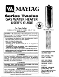
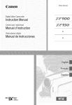
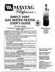
GAS WATER HEATER
USER'S GUIDE
For Your Safety
AN ODORANT IS ADDED TO THE GAS USED BY THIS
WATER HEATER
ModelNumbers
HX40NARS
HX40PARS
WARNING: If the information in these instructions are not fol- I
lowed exactly, a fire or explosion may result, causing property
damage, persona injury or death.
HX40PARTHX40NART
HX40PQRTHX40NQRT
HX40NQRT2
HX40PQRT2
HX50NART
HXSOPART
HXSONQRT
HXSOPQRT
HX50NQRT2
HX50PQRT2
HXSONQRT5W
HXSOPQRTSW
HX50NQRT52W
HXSOPQRT52W
HX75NQRS
HX75PQRS
-Do not store or use gasoline or other flammable vapors and liquids in the vicinity of this or any other appliance.
-WHAT TO DO IF YOU SMELLGAS
• Do not try to light any appliance.
• Do not touch any electrical switch; do not use any phone in
your building.
• Immediately call your gas supplier from a neighbor's phone.
Follow the gas supplier's instructions.
• If you can not reachyour gas supplier, call the fire department.
-Installation and service must be performed by a qualified installer,
serviceagency or the gas supplier.
•,WARNING
Improper installation, adjustment, alteration, service or maintenance can cause DEATH, SERIOUS BODILY INJURY,OR PROPERTY
DAMAGE. Refer to this manual for assistanceor consult the local
gas utility for further information.
•,WARNING
Flammable vapors may be drawn by air currents from other
areas of the structure to this appliance.
& WARNING
READ THE GENERAL SAFETY SECTION BEGINNING ON INSIDE
COVER AND THEN THIS ENTIRE MANUAL BEFORE INSTALLING
OR OPERATING THIS WATER HEATER.
Save this Manual for Future Reference.
FOR POTABLE WATER
HEATING
ONLY
NOT SUITABLEFOR
SPACE HEATING
NOT FOR USE IN
MANUFACTURED
(MOBILE) HOMES
Caution:
Read and Follow All
Safety Rules and
Operating Instructions
Before
First Use of
This Product.
Safety Instructions
AWARNING
_,WARNING
Improper installation, adjustment, alteration, service
or maintenance can cause DEATH, SERIOUS BODILY
INJURY, OR PROPERTY DAMAGE. Refer to this manual for assistance consult your local gas utility or call
Maytag Service Specialist at 1-800-365-0024 for an
authorized servicer for further information.
At the time of manufacture this water heater was provided with a combination temperature-pressures relief
valve certified by a nationally recognized testing laboratory that maintains periodic inspection of production
of listed equipment or materials, as meeting the
requirements for Relief Valves and Automatic Gas
Shutoff Devices for Hot Water Supply Systems, and
the latest edition of ANSI Z21.22 and the code require-
_,WARNING
requirements
of local
codes, but
lessmust
than meet
a combiments of ASME,
If replaced,
the not
valve
the
nation temperature and pressure relief valve certified
as meeting the requirements for Relief Valves and
Automatic Gas Shutoff Devices for Hot Water Supply
Systems, ANSI Z21.22 by a nationally recognized testing laboratory that maintains periodic inspection of
production of listed equipment or materials.
The valve must be marked with a maximum set pressure not to exceed the marked hydrostatic working
pressure of the water heater (150 Ibs./sq, in.) and a
discharge capacity not less than the water heater
input rate as shown on the model rating plate.
(Electric heaters - watts divided by 1000 x 3415 equal
BTU/Hr. rate.)
Your local jurisdictional authority, while mandating the
use of a temperature-pressure relief valve complying
with ANSI Z21.22 and ASME, may require a valve model
different from the one furnished with the water heater.
Compliance with such local requirements must be satisfied by the installer or end user of the water heater
with a locally prescribed temperature-pressure relief
valve installed in the designated opening in the water
heater in place of the factory furnished valve.
For safe operation of the water heater, the relief valve
must not be removed from it's designated opening or
plugged.
. ....
The temperature-pressure
relieT valve must De
installed directly into the fitting of the water heater
designated for the relief valve. Position the valve
downward and provide tubing so that any discharge
will exit only within 6 inches above, or at any distance
below the structural floor. Be certain that no contact is
made with any live electrical part. The discharge opening must not be blocked or reduced in size under any
circumstances. Excessivelength, over 30 feet, or use of
WATER HEATERS EQUIPPED FOR ONE TYPE GAS I
I ONLY: This water heater is equipped for one type
gas only. Check the model rating plate near the gas
control valve for the correct gas. DO NOT USE THIS
WATER HEATER WITH ANY GAS OTHER THAN THE
ONE SHOWN ON THE MODEL RATING PLATE. Failure
to use the correct gas can cause problems which can
result in DEATH, SERIOUS BODILY INJURY, OR PROPERTY DAMAGE, If you have any questions or doubts
consult your gas supplier or local utility,
AWARNING
INSTALLATIONS IN AREAS WHERE FLAMMABLE LIQUIDS (VAPORS)ARE LIKELYTO BEPRESENTOR STORED
(GARAGES, STORAGE, AND UTILITY AREAS, ETC):
Flammable liquids (such as gasoline, solvents, propane
(LP) or butane, etc.), all of which emit flammable
vapors, may be improperly stored or used in such
areas. The gas water heater pilot light or main burner
can ignite such vapors. The resulting flashback and fire
can cause death or serious burns to anyone in the
area, as well as property damage.
If installation in such areas is your only option, then
the installation must be accomplished in a way that
the pilot flame and main burner flame are elevated
from the floor at least 18 inches. While this may reduce
the chances of flammable vapors from a floor spill
being ignited, gasoline and other flammable substances should never be stored or used in the same
room or area containing a gas water heater or other
open flame or spark producing appliance,
NOTE: Flammable vapors may be drawn by air currents
from other areas of the structure to the appliance,
more
four elbows
canofcause
restriction and
reducethan
the discharge
capacity
the valve.
No valve or other obstruction is to be placed between
the relief valve and the tank. Do not connect tubing
directly to discharge drain unless a 6" air gap is provided. To prevent bodily injury, hazard to life, or property
damage, the relief valve must be allowed to discharge
water in quantities should circumstances demand. If
the discharge pipe is not connected to a drain or other
suitable means, the water flow may cause property
damage.
The Discharge Pipe:
• Must notbe smaller in size than the outlet pipe size
of the valve, or have any reducing couplings or
other restrictions.
Must not be plugged or blocked.
Must be of material listed for hot water distribution.
AWARNING
If this water heater will be used in beauty shops,
barber shops, cleaning establishments, or self-service laundries with dry cleaning equipment, it is
imperative that the water heater or water heaters
be installed so that combustion and ventilation air
be taken from outside these areas. Refer to the
"Locating The New Water Heater" section of this
manual and also the latest edition of the National
Fuel Gas Code, ANSI Z223.1, also referred to as NFPA
54 for specifics provided concerning air required,
AWARNING
A fire can start if combustible materials such as
clothing, cleaning materials, or flammable liquids
are paced aga nst or next to the water heater.
2
of
both
temperature-pressure
relief valve,
and
Must
be the
installed
so as to allow complete
drainage
the discharge pipe.
Must terminate at an adequate drain.
Must
not have any valve between the relief valve
and tank.
Safety Instructions
AWARNING
AWARNING
A gas water heater cannot operate properly without
the correct amount of air for combustion. Do not
install in a confined area such a closet, unless you
provide air as shown in the "Locating The New
Water Heater" section. Never obstruct the flow of
ventilation air. If you have any doubts or questions
at all, call your gas company. Failure to provide the
This water heater must not be installed directly on
carpeting. Carpeting must be protected by a metal
or wood panel beneath the appliance extending I
beyond the full width and depth of the appliance by I
at least 3 inches (76.2mm) in any direction, or if the
appliance is installed in an alcove or closet, the
entire floor must be covered by the panel. Failure to
proper amount of combustion air can result in a fire
or explosion and can cause DEATH, SERIOUS BODILY
INJURY,OR PROPERTY DAMAGE,
heed th s warning may resu t n a f re hazard.
AWARNING
AWARNING
VENT DAMPERS - Any vent damper, whether it is
operated thermally or otherwise must be removed if
its use inhibits proper drafting of the water heater.
Thermally Operated Vent Dampers: Gas-fired water
heaters having thermal efficiency in excess of 80%
may produce a relatively low flue gas temperature.
Such temperatures may not be high enough to properly open thermally operated vent dampers. This
would cause spillage of flue gases and may cause
carbon monoxide poisoning.
Vent dampers must bear evidence of certification as
complying with the latest edition of American
National Standard ANSI Z21.68 (ANSI Z21.66 & 67,
respectively, cover electrically and mechanically actuated vent dampers). Before installation of any vent
damper, consult your local gas utility for further
information,
HOTTER WATER CAN SCALD: Water heaters are
intended to produce hot water. Water heated to a
temperature which will satisfy clothes washing, dish
washing, and other sanitizing needs can scald and
permanently injure you upon contact. Some people
are more likely to be permanently injured by hot
water than others, These include the elderly, children,
the infirm, or physically/mentally
handicapped. If
anyone using hot water in your home fits into one of
these c_roupsor if there is a local code or state law
requiring a certain temperature water at the hot
water tap, then you must take special precautions. In
addition to using the lowest possible temperature
setting that satisfies your hot water needs, a means
such as a mixing valve, should be used at the hot
water taps used by these people or at the water
heater. Mixing valves are available at plumbing supply or hardware stores. Follow manufacturers instructions for installation of the valves. Before changing
the factory setting on the thermostat,
read the
'_Temperature Regulation" section in this manual.
AWARNING
• The appliance and its individual shutoff valve must
be disconnected from the gas supply piping system
during any pressure testing of the gas system at
test pressures in excess ofl/2 pound per square
inch (3.SkPa).
• The appliance must be isolated from the gas supply piping system by closing its individual manual
shutoff valve during any pressure testing of the
gas supply piping system at test pressures equal or
less than 1/2 pound per square inch (3.5kPa),
AWARNING
Soot build-up indicates a problem that requires correction before further use. Turn 'off" gas to water
heater and leave "off"
until repairs are made,
because failure to correct the cause of the sooting
can result in a fire or explosion causing DEATH, SERIOUS BODILY INJURY,OR PROPERTY DAMAGE.
AWARNING
AWARN[NG
BEFORE LIGHTING [PROPANE (L.P.) GAS WATER
HEATERS]: Propane (L.P.) gas is heavier than air.
Should there be a leak in the system, the gas will settie near the ground. Basements, crawl spaces, skirted
areas under manufactured (mobile) homes (even
when ventilated), closets and areas below ground
level will serve as pockets for the accumulation of
this gas. Before attempting to light or relight the
water heater's pilot or turning on a nearby electrical
light switch, be absolutely sure there is no accumu-
Chemical vapor corrosion of the flue and vent system may occur if air for combustion contains certain
chemical vapors. Spray can propellants, cleaning solvents, refrigerator and air conditioner refrigerants,
swimming pool chemicals, calcium and sodium chloride, waxes, bleach, and process chemicals are typical compounds which are potentially corrosive.
ing at ground level in the vicinity of the appliance. If
odor is detected, follow steps indicated at "For Your
lated gas
Safety"
oninthe
the cover
area. page
Search
of for
thisodor
manual
of gas
then
by leave
sniffthe premises.
Obstructed or deteriorated vent systems may
sent a serious hea th
AWARNING
risk or asphyx at on.
pre3
Safety Instructions continued on page 4.
J
Safety Instructions
AWARNING
The water heater with draft hood installed must be
c_rOperlyvented to a chimney which terminates outoors. Never operate the water heater unless it is
vented to the outdoors and has adequate air supply
to avoid risks of improper operation, explosion or
asphyxiation.
AWARNING
Minimum clearances between the water heater and
combustible construe!on are 1" at the sides and rear,
4 at the front, and 6' from the vent pipe. Clearance
from the top of the jacket is 18" on most models.
Note that a lesser dtmension may be allowed on
some models. Refer to the label on the water heater
adjacent to the gas control valve for all clearances.
AWARNING
IFIood damage to a_may
not be readily
|visible or immediately detectible. However, over a
"period of time a flooded water heater will create
dangerous conditions which can cause DEATH, SERIOUS BODILY INJURY, OR PROPERTY DAMAGE.
Contact the Maytag Contractor Dealer from whom
the appliance was purchased or call a Maytag
Service Specialist at 1-800-365-0024 for an authorized servicer to replace a flooded water heater, Dc
not attempt to repair the unit! It must be replaced!
AWARNING
INSULATING JACKETS: When installing an external
water heater insulation jacket on a gas water heater:
• DO NOT cover the temperature-pressure relief valve,
• DO NOT put insulation over any part of the top of
the gas water heater.
• DO NOT put insulation over the gas control valve or
gas control valve/burner cover, or any access areas
to the burner.
• DO NOT let insulation around the gas water heater
to get within 8 inches of the floor (air must get to
the burner).
• DO NOT cover or remove operating instructions,
and safety related warning labels and materials
affixed to the water heater.
Failure to heed this will result in the possibility of a
fire or explosion.
WATER HEATERS EVENTUALLY
ACAUTION LEAK: Installation of/j
the water heater must be accomplished in such a|
manner that if the tank or any connections should|
leak, the flow of water will not cause damage to J
the structure. For this reason, it is not advisable to
install the water heater in an attic or upper floor. I
When such locations cannot be avoided, a suitable l
drain pan should be installed under the water_
heater. Drain pans are available at your local hardware store. Such a drain pan must be not greater
than 1_½inches deep, have a minimum length and
width of at least 2 inches greater than the water
heater dimensions and must be piped to an adequate drain. The pan must not restrict combustion
air flow. Under no circumstances is the manufactur-
AWARNING
HYDROGEN GAS: H_can
be produced in
a hot water system that has not been used for a
long period of time (generally two weeks or more).
Hydrogen gas is extremely flammable and explosive.
To prevent the possibility of injury under these conI ditions, we recommend the hot water faucet be
opened for several minutes at the kitchen sink
before any electrical appliances which are connected
to the hot water system are used (such as a dishwasher or washing machine). If hydrogen gas is present, there will probably be an unusual sound stmilar to air escaping through the pipe as the hot water
faucet is opened. There must be no smoking or open
flame near the faucet at the time it is open.
age in connection with this water heater.
er or Maytag to be held liable for any water dam-
Table of Contents
Safety Instructions ...........................................................................................
2-4
Table of Contents .............................................................................................
5
Customer Information ....................................................................................
.6
Product Specifications .....................................................................................
6,7
Accessories and Tools Needed .......................................................................
8
Accessories ..................................................................................................................................................................
Tools
.8
................................................................................................................................................................................
8
Instructions
for Installation ...........................................................................
9-19
Removing the Old Water Heater ........................................................................................................................................
Typical Installation .........................................................................................................................................................
Locating the New Water Heater ..............................................................................................................................
Combustion Air and Ventilation for Appliances in Unconfined Spaces .............................................................................
Combustion Air and Ventilation for Appliances in Confined Spaces ..........................................................................
Water Piping ...................................................................................................................................................................
Temperature-Pressure Relief Valve ....................................................................................................................................
Filling the Water Heater. .......................................................................................................................................................
Venting. ........................................................................................................................................................................
Gas Piping .............................................................................................................................................................
Installation Checklist .....................................................................................................................................................
11,
12,
16,
17,
.9
10
12
12
13
14
15
16
17
18
19
Instructions
for Operation ..............................................................................
20-22
Lighting ....................................................................................................................................................................
20, 21
Temperature Regulation. .................................................................................................................................................
.22
Service and Maintenance ................................................................................
23-25
Venting System Inspection. ...............................................................................................................................................
Burner Inspection .............................................................................................................................................................
L.I_ Gas Control Valve and Burner Assembly Replacement Information .........................................................................
Burner Cleaning ...............................................................................................................................................................
Draining ...........................................................................................................................................................................
Temperature-Pressure Relief Valve Operation ...............................................................................................................
Drain Valve Washer Replacement ..................................................................................................................................
Housekeeping .................................................................................................................................................................
Service ...............................................................................................................................................................................
23
..23
.24
24
.24
.25
..25
25
,25
Trsorub
lee
oshooring....:_........_2:::::::.z:Z:._:.........Z_z..:.:._...::::::::::::::::::::::::
Condensation .............................................................................................................................................................
26
Smoke/Odor
..............................................................................................................................................................
Thermal Expansion ....................................................................................................................................................
Strange Sounds. .............................................................................................................................................................
Operational Conditions .............................................................................................................................................
Smelly Water ..............................................................................................................................................................
Air in Hot Water Faucets ............................................................................................................................................
High Temperature Shut Off System ............................................................................................................................
Not Enough Hot Water ............................................................................................................................................
Water is too Hot ........................................................................................................................................................
Leakage Checkpoints ....................................................................................................................................................
.26
26
26
27, 28
.27
27
27
.27
28
29
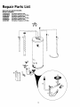
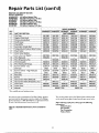
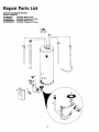
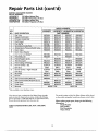
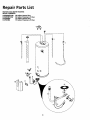
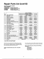
Repair Parts List ...................................................................................................................................
30-37
Warranty ............................................................................................................
.40
5
Customer Information
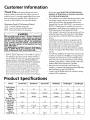
Thank You for purchasing a Maytag water heater,
the first few pages, READ THE ENTIRE MANUAL
BEFORE ATTEMPTING
TO INSTALL OR OPERATE THE WATER HEATER.
" The installation must conform with the instructions in this
manual; gas company rides; and Local Codes, or in the
absence of Local Codes, with the latest edition of the
National Fuel Gas code, ANSI Z223.1, also referred to as
Properly installed and maintained, it should give you years of
trouble free service, it is strongly suggested that this new water
heater be professionally installed, contact a Maytag Service
Specialist (1-800-365-0024) for recommended installers,
Abbreviations
Found In This Instruction
Manual
CSA - Canadian Standards Association
ANSI - American National Standards institute
NFPA - National Fire Protection Association
NEPA 54. This publication is available from your local
government or public library or gas company or by writing
NFPA, Batterymarch Park, Quincy, MA 02269.
• After reading this manual you have any questions or do not
understand any portion of the instructions, call a Maytag
Service Specialist at 1-800-365-0024 for an authorized
servicer.
_,WARNING
This gas-fired water heater is design certified by
CSA INTERNATIONAL
under American National
Standard/CSA Standard for Gas Water Heaters ANS
Z21.10.1 • CSA 4.1 (latest edition). The installation
must conform with this manual, Local Codes and
with the latest edition of the National Fuel Gas
Code, ANSI Z223.1.
This publication is available from your local government or public library, gas company, or by writing
NFPA, Batterymarch Park, Quincy, MA 02269.
Carefully plan the place where you are going to put the
water heater. Correct combustion, vent action, and vent
pipe installation are very important in preventing death
from possible carbon monoxide poisoning and fires.
Examine the location to ensure the water heater complies
with the "Locating the New Water Heater" section in this
manual.
Read the "Safety Instructions" section, pages 2, 3 and 4 of
this manual first and then the entire manual carefully. If
you don't follow the safety rules, the water heater will not
operate properly. It could cause DEATH, SERIOUS
BODILY INJURY AND/OR PROPERTY DAMAGE.
• This manual contains instructions for the installation,
• For California installation this water heater must be braced,
anchored, or strapped to avoid falling or moving during an
earthquake. See instructions for correct installation procedures. Instructions may be obtained from your local dealer,
wholesaler, public utilities or California Office of the State
Architect, 400 P Street, Sacramento, CA 95814.
operation, and maintenance of the gas-fired water heater.
It also contains warnings through out the manual that you
must read and be aware o£ All warnings and all instructions are essentialto the proper operation of the water
heater and your safety. Since we cannot put everything on
• Massachusetts Code requires this water heater to be
installed in accordance with Massachusetts 248-CMR 2.00:
State Plumbing Code and 248-CMR 5.00.
• Complies with SCAQMD rule #1121 and districts having
equivalent NOx requirements.
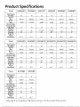
Product Specifications
•Model
HX40NARS
I-/X40PARS
HX40NART
HX40PART
HX40NQ.RT
HX40PQRT
Tank Capacity
In Gallons
40
40
40
40
40
40
Type of
Gas
B.T.U.
Natural
Propane
Natural
Propane
Natural
Propane
Rate
Recovery Rate
In Gals Per Hour
@ 900F Rise
Minimum
40_000
401000
40_000
40,000
52,500
52,500
41
41
41
41
54
54
Vent Pipe
Diameter
3" or 4"
20"
3" or 4"
20"
Y' or 4"
18"
3" or 4"
18"
4"
18"
4"
18"
Height To
Top of
Draft Hood
52"
52"
62V2"
6
621/2"
63V/'
63%"
Product Specifications
*Model
Tank Capacity
In Gallons
HX40NQRT2
HX40PQRT2
HXSONART
HXSOPART
HXg0NQRT
HXSOPQRT
40
40
50
50
50
50
Gas
B.T.U.
Natairal
Propane
Natural
Propane
Natural
Propane
Rate
Recovery Rate
In Gals Per Hour
@ 90°F Rise
Minimum
52,500
52_500
40,000
40,000
52,500
52,500
54
54
41
41
54
54
Vent Pipe
Diameter
4"
20"
4"
20"
3" or 4"
20"
3" or 4"
20"
4"
20"
4"
20"
Height To
Top of
Draft Hood
631/4"
63V4"
63"
63"
621H '
621/2"
Typeof
*Model
Tank Capacity
In Gallons
HXSONQRT2
HXSOPQRT2
HXSONQRTSW
HXSOPQRT5W
HX50NQRT52W
HXSOPQRT52W
50
50
50
50
50
50
Natural
Propane
Natural
Propane
Natural
Propane
Rate
Recovery Rate
In Gals Per Hour
@ 90°F Rise
Minimum
52,500
52_500
65_000
65,000
65!000
65_000
54
54
66
66
66
66
Vent Pipe
Diameter
4"
22"
4"
22"
4"
22"
4"
22"
4"
24"
4"
24"
Height To
Top of
Draft Hood
62Vz"
62'/z"
633/4"
633/4"
633/4"
63V4"
Type of
Gas
B.T.U.
*Model
Tank Capacity
In Gallons
Type of
Gas
B.T.U.
Rate
HX75NQRS
HX75PQRS
75
75
Natural
Propane
75,000
55,000
Recovery Rate
In Gals Per Hour
@ 90°F Rise
Minimum
77
56
Vent Pipe
Diameter
4"
24"
4"
24"
Height To
Top of
Draft Hood
621/z"
62%"
* Adding suffLx"D" denotes high altitude. High altitude models have a B.T.U./Recovery Rate 10% less than shown.
7
Accessoriesand Tools Needed
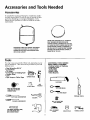
Accessories
To simplify the installation Maytag has available the installation parts shown below. You may or may not need all of these
accessories dependinF on your type of installation.
Call a
Maytag Service Speoalist at 1-800-365-0024
for an authorized installer.
DRAIN PANSAVAILABLEIN 22" DIAMETER
(PARTNUMBER9001609] FORWATER
HEATERSHAVING A DIAMETER20" OR LESS,
24_ DIAMETER(PARTNUMBER9002769) FOR
WATERHEATERSHAVINGA DJAMETER22"
OR LESSAND 28" DIAMETER(PARTNUMBER
9001608) FORWATERHEATERSHAVING A
DIAMETER26" OR LESS
EXPANSIONTANKSFORTHERMALEXPANSION
CONDITIONSAVAILABLEIN 2 GALLON(PART
NUMBER ETC2X)AND 5 GALLON(PARTHUMBERETC5X)CAPACITY
Tools
You may or may not need all of these tools, depending on your
type of installation. These tools can be purchased at your local
hardware store.
ADDITIONAL TOOLS NEEDED
WHEN SWEAT SOLDERING
• Tubing Cutters or Hacksaw
• Pipe Wrenches
• Screwdriver
•• Propane
Torch
Soft Solder
• Solder Flux
•
•
•
•
(2) 14"
6 Foot Tape of Folding
Garden Hose
Drill
TinSnips
Rule
* Wire Brushes
_
i
6 FOOTTAPE
_
•EmervCIoth
wPEPNEcH
ROLLOF TEFLONTAPE
(USEONLYON WATER
CONNECTIONS)
• Pipe dope or Teflon Tape
_
3/4" WIRE BRUSH
C_1/2"
__HACKSAW
GA_HOSE/'-,---_
7
SLOT-HEADSCREWDRIVER
_
PROPANETORCH
TIN SNIPS
_;_
ROLLOF LEADFREE
SOFTSOLDER
PHILLIPSSCREWDRIVER
PIPEDOPE(SQUEEZETUBEI
(USECONNECTIONS)
FORWATERAND
GAS
WIREBRUSH
I
ROLLOF EMERY
CLOTH
_
_
8
SOLDERFLUX
TUBINGCUTTER
Instructions for Installation
Removing
the Old Water Heater
Turn "OFF" the gas supply to the water heater.
(_
Disconnect the vent pipe from the draft hood where they
connect to the water heater. In most installations the vent
A WARNING
pipe canare
be removed.
lifted offafter
anyofscrew
or other
attached
devices
Dispose
the draft
hood.
The new
|If the main _lasline shutoffservingall gas appliancesis used,
|also shut "off" the _as at eachappliance.Leaveall gasappliLancesshut"off" unti/the water heaterinstallationiscomplete,
water heater has the draft hood which must be used for
proper operation.
Q
a,_
"OFF" the watcr
to the water
QTurn
heater. Some installations rcquire
that
the water be turned off to the entire
house.
_
a. If you have copper piping to the water
ocop
be cut with a hacksaw approximately
four inches away from where they connect to the water heater. This will
avoid cutting off the pipes too short.
_
necessary. Disconnect the temperaturepressure relief valve drain fine. When
the
water heater
is drained,
Additional
cuts can
be madedisconnect
later if
the hose from the drain valve. Close
the drain valve. The water heater is
__
(_
now completely disconnected and
_)
ready to be removed.
Check
to make sure the
ply is "OFF"again
to the water heater.gasThenSUp-
I _
from the gas control valve.
r
Attach a hose to the water heater drain
valve and put
in a floor
disconnect
the the
gasother
supplyend
connection
drain or outdoors. Open the water
heater drain valve. Open a nearby hot
water faucet which will relieve pressure
in the water heater and speed draining,
_
_
[_,._)
¢
'_
r _
b. If you have galvanized pipe to the water
with a pipe wrench at the union in each
fine. Also disconnect the piping
remaining to tile water heater. These
pieces should be saved since they may
be
needed
when
the pipes
new
heater,
loosen
thereconnecting
two galvanized
water heater. Disconnect the temperaCure-pressure relief valve drain line.
When the water heater is drained, disconnect the hose from the drain valve.
Close the drain valve. The water heater
i:e:dTt °c°_ Prl:t:°lYeddi's
c° nnect ed and
iI CAUTION
]
Thewater passingout of the drain valve may beextremelyhot.
Toavoidbeingscalded,makesureall connections
aretight and I
that thewater flow isdirectedaway fromanyperson.
i
__,
,_
A WARNING
Q
[
Mineralbuildupor sedimentmay haveaccumulatedin the old I
water heater.Thiscausesthe water heaterto be muchheavier
9
thannormalandthis residue,if spilledout, couldcausestaining.
Instructions for Installation (cont'd)
CHECKALL CONNECTIONS FOR LEAKS. CONSULTTHE LOCAL UTILITY COMPANY TO EXAMINE INSTALLATION FOR PROPRIETYAND SAFETY.
_
VACUUM RELIEF REQUIRED BY SOME CODES
(REFER TO LOCAL CODES)
HOT WATER OUTLET
TO CHIMNEY
TEMPERED
_[-_(_
COLD WATER INLET
_0_
WATER OUTLET '----_
*MIXING
_
VALVE
su%Sy
T E-PRESS°RE
_
m[_
DRAIN PA
_
DISCHARGE PIPE
II
-
(Do not cap or plug)
WLW
_'_
TO SUITABLE DRAIN
This appliance has been design certified as complying with American National Standard/CSA Standard for water heaters and is consideredsuitable for:.
Water (Potable) Heating All models are 'considered suitable for water (potable) heating."
AWARNING
A WARNING
HOTTER WATER CAN SCALD: Water heaters are
intended to produce hot water. Water heated to a
temperature
will sanitizing
satisfy clothes
dish washing, which
and other
needs washing,
can scald
This water heater shall not be connected to any heating systems or component(s) previously used with a
non-potable water heating appliance.
and permanently injure you upon contact. Some
people are more likely to be permanently injured by
children,
hot water the
than
infirm,
others.
or physically/mentally
These include the elderly,
handicapped. If anyone using hot water in your home fits
into one of these groups or if there is a local code or
state law requiring a certain temperature water at
the hot water tap, then you must take special precautions. In addition to using the lowest possible
temperature settingthat
satisfies your hot water
needs, a means such as a mixing valve, should be
used at the hot water taps used by these people or
at the water heater. Mixing valves are available at
plumbing supply or hardware stores. Follow manufacturers instructions for installation
of the valves.
Before changing the factory setting on the thermostat, read the "Temperature Regulation" section in
this manual.
_. WARNING
Toxic chemicals such as used for treatment of boilers
or non-potable water heating appliances shall never
be introduced into a potable water space heating
system.
NOTE: To protect against untimely corrosion of hot and
cold water fittings, it is strongly recommended that di-electric unions or couplings be installed on this water heater
when connected to copper pipe.
10
Instructions for Installation (cont'd)
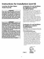
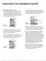
Locating
Heater
the New Water
&WARNING
You should carefully choose an indoor location for the new
water heater, because the placement is a very important consideration for the safety of the occupants in the building and
for the most economical use of the appliance. This water
heater is not for use in manufactured
doorinstanafion,
This water heater must not be installed directly on
carpeting. Carpeting must be protected by a metal
or wood panel beneath the appliance extending
beyond the full width and depth of the appliance
by at least 3 inches (76.2mm) in any direction, or if
the appliance is installed in an alcove or closet, the
entire floor must be covered by the panel. Failure to
(mobile) homes or out-
heed th s warn ng may resu t n a fire hazard.
Whether replacing an old water heater or putting tile water
heater in a new location, the following critical points must be
observed.
_k WARNING
Minimum clearances between the water heater and
combustible construction are 1" at the sides and
rear, 4" at the front, and 6" from the vent pipe.
[Clearance from the top of the jacket is 18" on most
models. on
Note
that
a lesser
be
allowed
some
models.
Referdimension
to the labelmay
on the
The location selected should be indoors as close as practical to
the gas vent or chimney to which the water heater vent is going
to be connected, and as centralized with the water piping system
as possible. The water heater, as all water heaters, will eventually
leak. Do not install without adequate drainage provisions where
water flow will cause damage,
i
water heater adjacent to the gas control valve for
all clearances.
_,CAUTION
WATER HEATERS EVENTUALLY LEAK: Installation of
manner that if the tank or any connections should
leak, the flow of water will not cause damage to
the structure. For this reason, it is not advisable to
the
water
must be
in such
install
the heater
water heater
in accomplished
an attic or upper
floor.a
When such locations cannot be avoided, a suitable
drain pan should be installed
under the water
heater. Drain pans are available at your local hardware store. Such a drain pan must be not greater
12"MAX.
-_
HIN.
VENTILATION
Alp,
OPENINGS O
i
_
than 1½ inches deep, have a minimum length and
width of at least 2 inches greater than the water
heater dimensions and must be piped to an ade-
FRONTVIEW
OFOOOR
_MII..N
_
MIN"
q
TOPVIEW
OF
CLOSET
TOPVIEW
_gl 4"MIN.
I" MIN.
WtTHOUT
C_4_.OROFCLOSET
_'HAX
WITHDOOR-I RECTANGUL_P,
[ 3"
_MIN
, ,.oucr
AlP,DUCT
. __,
quate
drain.
Thenopan
must not restrict
combustion
air flow.
Under
circumstances
is the manufacturer or Maytag to be held liable for any water damage in connection with this water heater.
I Figure 1 I
AWARNING
Propellants of aerosol sprays and volatile compounds, (cleaners, chlorine based chemicals, refrigerants, etc.) in addition to being highly flammable
in man
cases, will also change to corrosive
hydroch_/^ric.vacid when exposed to the combustion
_roducts of the water heater. The results can be
azardous, and also cause _roduct failure,
AWARNING
i A gas water heater cannot operate properly with'out the correct amount of air for combustion. Do
not install in a confined area such a closet, unless
you provide air as shown in the "Locating The New
Water Heater" section. Never obstruct the flow of
ventilation air. if you have any doubts or questions
at all, call your gas company. Failure to provide the
proper amount of combustion air can result in a fire
or explosion and can cause DEATH, SERIOUS BODILY NJURY, OR PROPERTY DAMAGE.
The location selection must provide adequate clearances for servicing and proper operation of the water heater.
11
Instructions for Installation (cont'd)
Locating the New Water
Heater (cont'd)
Combustion Air and Ventilation
for Appliances Located in
Unconfined Spaces
A WARNING
Unconfined
Space is a space whose volume is not less than
If this water heater will be used in beauty shops,
barber shops, cleaning establishments, or self-service laundries with dry cleaning equipment, it is
imperative
the water
heaterand
or ventilation
water heaters
be
installed that
so that
combustion
air
50 cubic feet per 1,000 Btu per hour of the aggregate input
rating of all appliances installed in that space. Rooms cornmunicating directly with the space in which the appliances are
installed, through openings not furnished with doors, are
be taken from outside these areas. Refer to the
"Locating The New Water Heater" section of this
manual and also the latest edition of the National
Fuel Gas Code, ANSI Z223.1, also referred to as NFPA
54 for specifics provided concerning air required,
considered a part of the unconfined space
In unconfined spaces in buildlngs, in£dtration may be adequate to provide air for combustion, ventilation and dilution
of flue gases.However, in buildings of tight construction (for
example, weather stripping, heavily insulated, caulked, vapor
barrier, etc.), additional air may need to be provided using the
methods described in Combustion Air and Ventilation for
AWARNING _
Appliances Located in Confined Spaces, b.
INSTALLATIONS IN AREAS WHERE FLAMMABLE LIQUIDS (VAPORS) ARE LIKELYTO BE PRESENTOR STORED
(GARAGES, STORAGE, AND UTILITY AREAS, ETC):
I Flammable liquids (such as gasoline, solvents, propane
(LP) or butane, etc.), all of which emit flammable
vapors, may be improperly
stored or used in such
areas. The gas water heater pilot light or main burner
Combustion Air and Ventilation
for pp,,ances Located in
Confined paces
_____i.
can ignite such vapors. The resulting flashback and fire
can cause death or serious burns to anyone in the
area, as well as property damage,
If installation in such areas is your only option, then
the installation must be accomplished in a way that
=
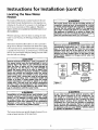
Conl_ned Space is a space whose volume is less than 50 cubic
feet per 1,000 Btu per hour of the aggregate input rating of all
appliances installed in that space.
a. ALL AIR FROM INSIDE BUILDINGS:
the pilot
main 18
burner
flame
are this
elevated
from
the flame
floor and
at least
inches.
While
may
reduce the chances of flammable vapors from a floor
spill being ignited, gasoline and other flammable substances should never be stored or used in the same
room or area containing a gas water heater or other
open flame or spark producing appliance,
NOTE: Flammable vapors may be drawn by air currents
from other areas of the structure to the appliance,
(See Page II Figure I, and Figure 2 below)
The confined space shall be provided with two permanent
openings communicating directly with an additional
room(s) of suffident volume so that the combined volume
of all spaces meets the criteria fur an unconfined space.
The total input of all gas utifization equipment installed in
the combined space shall be considered in making this
determination. Each opening shall have a minimum free
area of one square inch per 1,000 BTU per hour of the
total input rating of all gas utilization equipment in the
confined space, but not less than 100 square inches. One
opening shall commence within 12 inches of the top and
one commencing within 12 inches of the bottom of the
enclosure.
ASVENT
I
FUR
IFigure21
12
II
WATER
ER
[I..J
^_--
OPENINGS
Instructions for Installation (cont'd)
b. ALL AIR FROM OUTDOORS: (see Figures 3-5)
The confined space shall be provided with two permanent
openings, one commencing within 12 inches of the top
and one commencing within 12 inches from the bottom of
the enclosure. The openings shall communicate directly, or
by ducts, with the outdoors or spaces (crawl or attic) that
freely communicate with the outdoors.
3. When communicating with the outdoors through horizontal ducts, each opening shall have a minimum free area of 1
square inch per 2,000 BTU per hour of total input rating of
all equipment in the enclosure. (See Figure 5.)
Figure 5 ]
[ Figure 3 ]
4. When ducts are used, they shall be of the same cross-sec-
ALTINLETAIR VENTILATION
LOUVERS
tional area as the free area of the openings to which they
connect. The minimum short side dimension of rectangular
1. When directly communicating with the outdoors, each
opening shall have a minimum free area of 1 square inch
per 4,000 BTU per hour of total input rating of all equipment in the enclosure. (See Figure 3.)
air ducts shall not be less than 3 inches. (See Figure 5.)
5. Louvers and Grilles: In calculating free area, consideration
shall be given to the blocking effect of louvers, grilles or
screens protecting openings. Screens used shall not be
2. When communicating with the outdoors through vertical
ducts, each opening shall have a minimum free area of 1
square inch per 4,000 BTU per hour of total input rating of
smaller than % inch mesh. If the free area through a design
of louver or grille is known, it should be used in calculating
the size opening required to provide the free area specified.
all equipment in the enclosure. (See Figure 4.)
If the design and free area is not known, it may be assumed
that wood louvers will be 20-25 percent free area and metal
louvers and grilles will have 60-75 percent free area.
Louvers and grilles shall be fixed in the open position or
interlocked with the equipment so that they are opened
automatically during equipment operation.
Figure
4
6. Special Conditions Created by Mechanical Exhausting or
Fireplaces: Operation of exhaust fans, ventilation systems,
clothes dryers or fireplaces may create conditions requiring
attention
avoid
of
special
to
unsatisfactory operation
installed gas utilization equipment.
]
13
Instructions for Installation (cont'd)
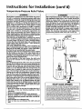
Water Piping
AWARNING
HOTTER WATER CAN SCALD: Water heaters
are
intended to produce hot water. Water heated to a
temperature
which will satisfy clothes washing,
dish washing, and other sanitizing needs can scald
and permanently injure you upon contact. Some
people are more likely to be permanently injured by
hot water than others. These include the elderlv,
children, the infirm, or physically/mentally
hand]capped. If anyone using hot water in your home fits
into one of these groups or if there is a local code or
state law requiring a certain temperature water at
the hot water tap, then you must take special precautions. In addition to using the lowest possible
temperature settingthat
satisfies your hot water
needs, a means such as a mixing valve, should be
used at the hot water taps used by these people or
at the water heater. Mixing valves are available at
_alumbing supply or hardware stores. Follow manucturers instructions for installation of the valves.
Before changing the factory setting on the thermo-
star, manual.
this
read the "Temperature
Regulation"
section in
2. Look at the top cover of the water heater. The cold water
inlet is marked cold. Connect the cold water pipe to the
cold water inlet of the water heater.
NOTE:
This water heater is super insulated to minimize
heat lossfi'om the tank. Further reduction in heat loss
can be accomplished by insulating the hot waterlines
from the water heater.
I
I
I
l
THREADED
TO
SWEATCOUPLING
_
__
_/'___'_]
HOTOUTLET
SHUTOFF
VALVE
_
_
_1
[]_--_
COLDINLET
tems or component(s) used with a non-potable water heating
appliance.
If a water heater is installed in a closed water supply system;
such as one having a back-flow preventer, check valve, water
meter water
This
with heater
a checkshall
valve,
notetc..,
be connected
in the coldtowater
any heating
supply; sysmeans shall be provided to control thermal expansion.
Contact the local utility or call a Maytag Service Specialist at
1-800-365-0024 for an authorized installer on how to control this situation.
314_ THREADED-TOCOUPLING
HOUSE
_
_._HOT
--
3/4" THREADED
COUPLING
WATERLINE
_
TEMPERATUREPRESSURE
RELIEF
COLD_,
_
VALVE
NOTE: To protect against untimely corrosion of hot and
cold water fittings, it is strongly recommended that di-electric unions or couplings be installed on this water heater
when connected to copper pipe.
_
The illustration shows the attachment of the water piping to
the water heater. The water heater is equipped with 3/4inch
_/,_
NOTE: If using copper tubing, solder tubing to an adapter
"-_
before attaching the adaptor to the cold water inlet connection.
Do not solder the cold water supply line directly to the cold
//
water
It will harm the dip tube and damage the tank.
water inlet.
connections.
_'
'V
DISCHARGE
PIPE
(Do not cap
or plug)
_--
6"AIRGAP
_
I
FLOOR
DRAIN
1. Look at the top cover of the water heater. The water outlet
is marked hot. Connect the hot water pipe to the hot
water outlet on the water heater.
14
Instructions for Installation (cont'd)
Temperature-Pressure
Relief Valve
•,WARNING
_,WARNING
At the time of manufacture this water heater was provided with a combination temperature-pressuresrelief valve
certified by a nationally recognizedtesting laboratory that
maintains periodic inspection of production of listed
equipment or materials, as meeting the requirements for
Relief Valves and Automatic Gas Shutoff Devices for Hot
Water Supply Systems, and the latest edition of ANSI
Z21.22 and the code requirements of ASME. If replaced,
the valve must meet the requirementsof local codes,but
not less than a combination temperature and pressure
relief valve certified as meeting the requirements for
Relief Valves and Automatic Gas Shutoff Devices for Hot
Water Supply Systems,ANSI Z21.22 by a nationally recognized testing laboratory that maintains periodic inspection
of productionof listedequipment or materials.
The valve must be marked with a maximum set pressure
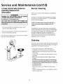
The temperature-pressure relief valve must be manually operated at least once a year. Caution should be
taken to ensure that (1) no one is in front of or
around the outlet of the temperature-pressure relief
valve discharge line, and (2) the water manually discharged will not cause any bodily injury or property
damage because the water may be extremely hot.
If after manually operating the valve, it fails to completely reset and continues to release water, immediately close the cold water inlet to the water heater,
follow the draining instructions, and replace the
temperature-pressure relief valve with a new one.
SHUTOFF
(Z_ VALVE
VALVE
the water heater (150 Ibs./sq. in.) and a dischargecapacity
not lessthan the water heater input rate as shown on the
model rating plate. (Electric heaters - watts divided by
1000 x 3415 equal BTU/Hr.rate.)
Your local jurisdictional authority, while mandating the
use of a temperature-pressurerelief valve complying with
ANSI Z21.22 and ASME, may require a valve model differnot from
to exceed
thefurnished
marked hydrostaticworking
pressureof
ent
the one
with the water heater.
HOT
COLD
___11
Compliancewith suchlocalrequirements must be satisfied
by the installer or end user of the water heater with a
locally prescribed temperature-pressure relief valve
installed in the designated opening in the water heater in
placeof the factory furnishedvalve.
For safe operation of the water heater, the relief valve
must not be removed from it's designated opening or
plugged,
The temperature-pressure relief valve must be installed
directly into the fitting of the water heater designated for
the relief valve. Positionthe valve downward and provide
tubing sothat any dischargewill exit only within 6 inches
above, or at any distance below the structural floor. Be
certain that no contact is made with any live electrical
part. The discharge opening must not be blocked or
reducedin size under any circumstances.Excessivelength,
over 30 feet, or use of more than four elbows can cause
restrictionand reducethe dischargecapacityof the valve.
No valve or other obstruction isto be placed between the
relief valve and the tank. Do not connecttubing directly to
dischargedrain unlessa 6" air gap is provided.To prevent
bodily injury, hazard to life, or property damage, the relief
valve must be allowed to discharge water in quantities
should circumstancesdemand. If the dischargepipe is not
connected to a drain or other suitable means, the water
flow may causeproperty damage.
The Discharge Pipe:
• Must not be smaller in size than the outlet pipe size of,
the valve, or have any reducing couplings or other
restrictions.
Must not be plugged or blocked,
Must be of material listedfor hot water distribution,
Must be installed so as to allow complete drainage of
both the temperature-pressure relief valve, and the discharge pipe.
Must terminate at an adequate drain,
Must not have any valve between the relief valve and
tank.
¢,_
_
TEMPEPJ_TUREPRESSURE
RELIEF
VALVE
plug)
6" AIRGAP
--
RELIEF
VALVE
m
FLOOR
DRAIN
L
OPENING
At the time of manufacture,thiswater heaterwas providedwith a combination
temperature-pressure
reliefvalvelistedascomplyingwith thestandardforrelief
valves
andautomatic
gasshut-off
devices
forhotwatersupply systems,
ANSI
z21.22.
Forsafeoperation
of thewaterheater, thereliefvalvemust
notbe
removedfrom itsdesignatedpointof installationor plugged.
Your local urisdictionalauthority, while mandating the use of a temperaturepressurerelief valve complyingwith ANSIZ21.22andASME,may requirea valve
model different fromthe onefurnishedwith the water heater.
Compliancewith suchlocal requirementsmustbe satisfiedby the installeror
end user of the water heater with a locallyprescribedtemperature-pressure
relief valve installedin the designatedopeningin the water heater.
Seemanual heading-"Temperature-Pressure
ReliefValves"for installationand
maintenanceof relief valve,dischargeline. and other safetyprecautions.
15
Instructionsfor Installation (cont'd)
Filling
the Water
Heater
_i CAUTION
Never use this water heater unless it is completely I
filled with water. Toprevent damage to the tank, I
the tank must be filledwith water. Water must flow
from the hot water faucet before turning "ON" gas I
to the water heater.
I
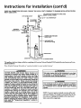
For proper venting in certain installations, a larger diameter
vent pipe may be necessary. Due to great variances in instanations, unforeseeable by the manufacturer of the water heater,
you must consult your gas company to aid you in determining
thethe
proper
water heater
the vent
tables
in
latestventing
edition for
of your
the National
Fuel from
Gas Code
ANSI
To fill the water heater with water:
•
Z223.1, also referred to as NFPA 54.
Close the water heater drain valve by turning the handle to
the right (clockwise). The drain valve is on the lower front
of the water heater,
Check the venting system for signs of obstruction or deterioration and replace if needed.
Open the cold water supply valve to the water heater.
NOTE: The cold water supply valve must be left open
when the water heater is in use.
The combustion and ventilation air flow must not be
obstructed.
•
To insure complete filling of the tank, allow air to exit by
•
until a constant flow is obtained. This willlet air out of the
opening
water
heater
the nearest
and the hot
piping,
water faucet. Allow water to run
Check all new water piping for leaks. Repair as needed.
Obstructed or deteriorated vent systems may
sent a serious health
AWARNING
risk or asphyxiat on.
pre• Place the draft hood legs in the receiving holes on the top
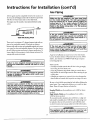
Venting
of
thefit.
water heater. The legs will snap in the holes to give a
tight
• Place the vent pipe over the draft hood. With the vent pipe
in position, drill a small hole through both the vent pipe
&WARNING
VENT DAMPERS - Any vent damper, whether it is
operated thermally or otherwise must be removed
itits use inhibits proper drafting of the water
heater.
Thermally Operated Vent Dampers: Gas-fired water
heaters having thermal efficiency in excess of 80%
may produce a relatively low flue gas temperature.
and draft hood. Secure them together with a sheet metal
screw.
Such temperatures
properly
open thermally
may operated
not be high
ventenough
dampers.
to
This wouldcause
spillage of flue gases and may
cause carbon monoxide poisoning.
Vent dampers must bear evidence of certification as
complying with the latest edition of American
National Standard ANSI Z21.68 (ANSi Z21.66 & 67,
respectively, cover electrically and mechanically actuated vent dampers). Before installation of any vent
damper, consult your local gas utility or local codes
for further information.
,"_"_.t__==ff=_ _t._ __%'%_'_-Y_
_
LVENTTOOUTDOORSOR
DRAFT
_IOOD_
-'"_'_ _ CHIMNEY
(
eT_i_e
)
DRAFT HOOD
_lr
_
J VENT_J
SCREW_
J $
DRAFTHOOD
&WARNING
The water heater with draft hood installed must be
dProperlyvented to a chimney which terminates outoors. Never operate the water heater unless it is
vented to the outdoors and has adequate air supply
to avoid risks of improper operation, explosion or
asphyxiation.
&WARNING
To insure proper venting of this gas-fired water
heater, the correct vent pipe diameter must be utilized, Any additions or deletions of other gas appliances on a common vent with this water heater
&WARNING
may adversely affect the operation
of the water
heater. Consult the local gas utility or call a Maytag
Service Specialist at 1-800-365-0024 for an autho-
I
I
The vent pipe from the water heater must be no I
less than the diameter of the draft hood outlet on I
I the water heater, and must slope upward to the I
Ichimney
rized servicer if any such changes are planned.
16
at least 1,:inch per linear foot.
I
Instructions for Installation (cont'd)
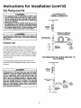
Gas Piping
All vent gases must be completely vented to the outdoors of
AWARNING
the structure (dwelling). Install only the draft hood provided
with the new water heater and no other draft hood.
Vent pipes must be secured at each joint with sheet metal
Make sure the gas supplied is the same type listed
on the model rating plate. The inlet gas pressure
must not exceed 10.5 in. water column (2.6kPa) for
natural gas or 13 in. water column (3.2kPa) for
propane (L.R) gas. The minimum inlet gas pressure
listed on the model rating plate is for the purpose
screws,
CHIMNEY
AWARNING
]
of the
inputgas
adjustment.
I If
control valve is subjected to pressures /
exceeding _ pound per square inch (3.5kPa), the /
damage to the gas control valve could result in a /
] TO
'
_
VENT PIPEINSTALLATION
fire or exp osion from eak ng gas.
j
There must be a minimum of 6" clearance between singlewall vent
AWARNING
pipe and any combustible material. Fill and seal any clearance
between single wall vent pipe and combustible material with mortar
]
If the main gas line shutoff serving all gas appli- ]
antes is used, also turn "off" the gas at each appli-|
ance. Leave all gas appliances shut off until the ]
mix,cement, or other noncombustible substance.For other than single wall, followvent pipe manufacturer'sclearance specifications.To
insure a tight fit of the vent pipe in a brick chimney,seal around the
water
vent pipe with mortar mix cement.
heater installation
is complete.
]
A gas line of sufficient size must be run to the water heater.
Consult the latest edition of National Fuel Gas Code ANSI
Z223.1, also referred to as NFPA 54 and the gas company
Failure to have required
&WARNING
clearances between
vent
concerning pipe size.
hazard.piping
and combustible material will resu t n a f re
There
must accessible
be:
• A readily
manual shut off valve in the gas supply
llne serving the water beater, and
• A drip leg (sediment trap) ahead of the gas control valve to
help prevent dirt and foreign materials from entering the gas
control valve.
AWARNING
Be sure vent pipe is properly connected to prevent
escape of dangerous flue gases which could cause
deadly asphyxiation.
• A flexible gas connector or a ground joint union between the
shutoffvalve and control valve to permit servicing of the unit.
AWARNING
Be sure to check all the gas piping for leaks before lighting the
water heater. Use a soapywater solution, not a match or open
Chemical vapor corrosion of the flue and vent system may occur if air for combustion contains certain
chemical vapors. Spray can propellants, cleaning solvents, refrigerator and air conditioner refrigerants,
swimming pool chemicals, calcium and sodium chloride, waxes, bleach, and process chemicals are typical compounds which are potentially corrosive.
flame. Rinse offsoapy solution and wipe dry.
Standard Models are for installation up to 3,300 feet above
sea level.
High Altitude Models are for installation from 3,300 to
5,500 feet above sea level.
Ifa standard model is installed above 3,300 feet or a high altitude model is installed above 5,500 feet, the input rating must
be reduced at the rate of 4 percent for each 1,000 feet above
sea level. Contact your local gas utility for further information.
AWARNING
I
The appliance and its gas connection must be leak I
testedbefore placing the appliance in operation.
]
17
Instructions for Installation (cont'd)
Gas Piping
(cont'd)
The appliance and its individual shutoff valve
must be disconnected from the gas supply piping
system during any pressure testing of the gas system at test pressures in excess of 1/2 pound per
square inch (3.5kPa).
The appliance must be isolated from the gas supply piping system by closing its individual manual
FLEXIBLE
CONNECTOR
GASSUPPLY
PIPING
/
shutoff valve during any pressure testing of the
gas supply piping system at test pressures equal
or less than 1/2 pound per square inch (3.5kPa).
li
AWARNING
MANUAL
SHUTOFF
VALVE
GAS PIPING
WITH
FLEXIBLE GAS CONNECTOR
A, WARNING
Use pipe joint compound or teflon tape marked as
being resistant to the action of petroleum [Propane
GROUNDJOINT
(L.R)]gases.
SEDIMENT
UNION (OPTIONAL)
LABELED AS COMPLYING
WITH ANSI STANDARDS
_
_
_
_
LOOP
_---_
TRAP
A sediment trap shall be installed
water
-_
heater as practical
as
at the time
close to the inlet
of water
heater
of the
DR_ILEGNT
3_ MIN
installa-
_
tion. The sediment trap shall be either a tee fitting with a
capped nipple in the bottom outlet or other device recognized
as an effective sediment trap. Ira tee fitting is used, it shall be
installed in conformance with one of the methods of installation shown below.
j
GASnt
_ TRAP) CAP
_ .......
"
GAS PIPING
Connecting the gas piping to the gas control valve of the
water heater can be accomplished by either of the two meth-
WITH ALL BLACK
GAS CONTROL
IRON
PIPE TO
GASSUPPLY'IPING
ods shown.
Contaminants
in theAWARNING
gas lines may cause improper I
SHUToFFMANUAL
VALVE _ F-]
I operation
of the gas Before
control attaching
valve thatthe
may
in fire or explosion.
gasresult
line II
be sure that all gas pipe is clean on the inside. To l
trap any dirt or toretgn material in the gas supply
line, a drip leg (sometimes called a sediment trap)
must be incorp.orated in the piping. The drip leg
must be readdy accessible. Install in accordance
JOINT _,_
UNION
_
_--_
GROUND
also
referred
as NFPAFuel
54. Gas Code, ANSI Z223.1
edition
of thetoNational
with the "Gas Piping" section. Refer to the latest
__
_,, ,,,_,
.......
18
P_
B_CKPIPE _
I I _R_I_GNTDRIP
LEG
I I TRAP)
COvNTLvROL
GAS
Instructions for Installation (cont'd)
Installation
Checklist
BEFORE LIGHTING THE PILOT:
CHECK FOR LEAKS
Check the gas lines for leaks.
a. Use a soapy water solution.
Be sure to check all your gas pipes for leaks before lighting
DO NOT
test for gas leaks
your water heater. Use a soapy water solution,
using a match or open flame,
open flame. Check
b. Brush the soapy water solution
on all gas pipes, joints
gas control
and fittings,
c. Check for bubbling soap. This means you have a leak.
Turn "OFF" gas and make the necessary repairs.
d. Recheck for leaks.
the factory gas fittings
knob is still in "PILOT"
OR CHIMNEY
Is the new temperature-pressure
relief valve properly
installed and piped to an adequate drain? See
•
Are the cold and hot water lines connected
instructions
SHUTOFFVALVE
HOT
COLD
to the water
in the
GAS SUPPLY
Is the water heater completely
"Filling"
section.
check the
Relief Valve" section.
heater correctly? See "Water Piping" instructions
.
.
.
_
.
Instructions
for Installation
section.
•
Then,
"ON". Use a soapy
VENT
PIPETO
OUTDOORS
e. Rinse off soapy solution and wipe dry.
"Temperature-Pressure
after pilot is lit and
position.
fittings when the main burner is turned
water solution for this, too.
not a match or
DRAFT HOOD
PRESSURE
RELIEF
VALVE
filled with water? See
in the "Instructions
for Installation"
SHUTOFF
VALVE
•
Will a water leak damage anything?
New Water Heater" section.
Is there proper clearance
between
See the "Locating
(Do not cap or plug)
the water heater
anything that might catch fire? See the "Locating
water Heater" section.
Do you have adequate ventilation
the
and
TEE
DRAINVALVE
the New
(Sediment trap)
PIPECAF --
so that the water heater
6 INCHAIR GAP
will operate properly? See "Combustion Air and Ventilation"
in the "Instructions
for Installation" section.
_
FLOORDRAIN
Is the draft hood vent piping properly secured? See
"Venting" instructions
in the "Instructions
for Installation"
section.
Is there proper clearance between the vent pipe and anything that might catch on fire? See "Venting" instructions
in the Instructions
for Installation
section.
__
_o
oa_
S_
_u¢_n
_o_..................
15o
,_,
wc
*°
AUTOMATIC
STORAGE
WATER
HEATER
Is the vent pipe_ properly,, sloped.
,. and does. the. vent terminate outdoors.
See Venting
mstmcnons
m the
"Instructions
for Installation"
section.
Do you need to call your gas company
_,._,
to check the gas
pipe and its hookup?
MODEL
19
RATING PLATE
w_
Instructions for Operation
BEFORE LIGHTING [PROPANE (L.P.) GAS WATER
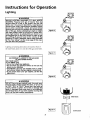
Lighting
HEATERS]: Propane_,WARNING
(L.P.) gas is heavier than air.
_
_
Should there be a leak in the system, the gas will
settle near the ground. Basements, crawl spaces,
skirted areas under manufactured (mobile) homes
(even when ventilated), closets and areas below
ground level will serve as pockets for the accumulation of this gas. Before attempting to light or relJght
the water heater's pilot or turning on a nearby electrical light switch, be absolutely sure there is no
accumulated gas in the area. Search for odor of gas
by sniffing at ground level in the vicinity of the
appliance. If odor is detected, follow steps indicated
at "For Your Safety" on the cover page of this man-
]
6
I Figure
U
,_
ual then leave the premises.
Lighting and operating instructioils are located on front o[
the water heater, above or to one side of the gas control valve.
I Figure 7
A, WARNING
AN ODORANT IS ADDED TO THE GAS USED
BY THIS WATER HEATER.
FOR YOUR SAFETY
IF YOU SMELL GAS:
Do not try to light any appliance.
Do not touch any electrical switch; do not use any
phone in your building.
Immediately call your gas supplier from a neighbor's phone. Follow the gas supplier's instructions.
If you cannot reach your gas supplier, call the fire
department.
f
I Figure 8
_,WARNING
DO NOT force the gas control knob. Use only your
hand to push it down to light the pilot, or to turn it
to "ON", "OFF" or "PILOT". Never use a tool such as
a lever, wrench or pliers. Do not hit or damage the
knob. A damaged knob may result in an explosion
and serious injury. If you have problem turning the
knob, call the gas supplier immediately.
(
I
I
I
20
I Figure 9 I
_
INNERDOOR
OUTERDOOR
1
Instructions for Operation (cont'd)
Lighting
label on the water
FOR YOUR
SAFETY
heater
as it appears
READ
above
BEFORE
the thermostat
LIGHTING
if you do not follow these instructions exactly, a fire or explosion
may resu t caus ng property
damage, persona njury or oss of I fe.
WARNING
A. Thisappliancehasa pilotwhichmustbe lightedby
hand.Whenlighting
thepilot,followtheseinstructions
exactly.
B.BEFORE
LIGHTING
smellallaroundtheappliance
area
for gas.Be sureto smellnextto thefloorbecause
somegasisheavier
thanairandwillsettleonthefloor,
WHATTODOIFYOUSMELLGAS
• Donottrytolightanyappliance.
• Donot touchanyelectricswitch;donot useany
phoneinyourbuilding,
= Immediately
callyourgassupplierfroma neighbor's
phone.Followthegassupplier's
instructions,
LIGHTING
I
• If youcannotreachyourgassupplier,callthefire
department.
C.Useonlyyourhandto pushinorturnthegascontrol
knob.Neverusetools.If theknobwillnotpushin or
turnbyhand,don'ttryto repairit, calla qualified
servicetechnician.
Forceorattempted
repairmayresult
inafireorexplosion.
D.Donotusethisappliance
if anyparthasbeenunder
water.Immediately
calla qualifiedservicetechnician
toinspect
theappliance
andtoreplaceanypartof the
controlsystemandanygascontrolwhichhasbeen
underwater.
INSTRUCTIONS
1.STOP!Readthesafetyinformation
aboveonthislabel.
2.Remove
outerdoor.
3. Setthethermostatto lowestsettingbyturningthe
watertemperature
dialclockwise,
(/ _ ) to itslowest
temperature
setting(witharrowondial)asshown.DO
NOTFORCE._
9. Pushin controlknoball theway and holddown.
immediately
lightthepilotwitha match.Continue
to
holdcontrolknobin for aboutone(1) minuteafter
thepilotis lit.Releaseknobanditwill popbackup.
Pilotshouldremainlit.If it goesout,repeatsteps3
through8.
e If knobdoesnotpopupwhenreleased,
stopand
immediately
callyourservicetechnician
or gas
supplier.
• It the pilotwill notstay lit after severaltries,
4. Turngascontrolknobclockwise_
to "OFF"posilion. Knobcannothe turnedfrom"PILOT"to "OFF"
unlessknobis depressed
slightly.DONOT FORCE,
(Figure6)
5. Waitfive(5) minutes
to clearoutanygas.It youthen
depressandturnthegascontrolknobclockwise
yourservicetechnician
_ ) to"OFF"andcalJ
.
.
orgassuppher.
(Figure6)
10.Replace
(orclose)innerdoor.(Figure9)
11. Atarmslengthaway,turngascontrolknobcounter-
smellgas,STOP!
Follow
"B" in thesafetyinformation
aboveonthislabel.If
youdon'tsmellgas,goto
the
nextstep.
6. Remove(oropen)innerdoorlocatedbelowthe gas
controlunit.
7. Findpilot-follow
metaltubefromgascontrol.Thepilot
islocatedinfrontoftheburner.
PILOT
BURNER
_
I'_ THERMOCOUPLE
clockwise
_
tothefull "ON"position.
Warning
do not use gas control knob to regulate gas
flow. (Figure8)
12.At armslengthaway,set thethermostat
to desired
setting.The mark( • ) indicativeof approximate
120°Fis preferredstartingpoint.Somelocallaws
mayrequirea lowerstartingpoint,if hotterwateris
desired,seeinstruction
manual
and"warning"below.
13.Closetheouterdoor.
II
8.If youdon'tsmellgas,turnknobongascontrolcounter
clockwise
__ to"PILOT"position.
(Figure7)
WARNING
Hotterwaterincreasestheriskof scaldinjury.Beforechangingtemperature
settingseeinstruction
manual.
TO TURN
OFF GAS TO APPLIANCE
1. Setthethermostatto lowestsettingbyturningthe
watertemperature
dialclockwise
(f_'_) to itslowest
temperature
setting(witharrowondial)asshown.DO
NOTFORCE. _
2.Turngascontrolknobclockwise0 _ to"OFF"position.Knobcannotbeturnedfrom"PILOT"to "OFF"
unlessknobisdepressed
slightly.
DONOTFORCE,
3.Closeouterdoor.
2]
Instructions for Operation (cont'd)
Temperature
Regulation
Due to the nature of the typical gas water heater, tile water
temperature in certain situations may vary up to 30°F higher or
lower at the point of use such as, bathtubs, showers, sink, etc.
Turn the water temperature dial clockwise __eff_(¢
_
decrease the temperature, or counterclockwise (
increase the temperature.
This means that when the temperature adjustment dial is set
at the mark approximating 120 ° F, the actual water temperaCureat any hot water tap could be as high as 150T or as low
as 90°E
Nt--
U
Any water heater's intended purpose is to heat water. Hot
water is needed for cleaning (bodies, dishes, clothing). Hot
water will present a scald hazard. Depending on the time element, and the people involved (normal adults, children, toddlers, elderly, infirm, etc.) scalding may occur at different
temperatures.
_'-
½
AWARNING
PILOT
HOTTER WATER CAN SCALD: Water heaters are
intended to produce hot water. Water heated to a
temperature which will satisfy clothes washing, dish
washing, and other sanitizing needs can scald and
permanently injure you upon contact. Some people
are more likely to be permanently injured by hot
) to
LIGHTING-
o
Set here before attempting m light
pilot.
A-
Is a thermostat setting ofapproximately 120°F, which will supply hot
water at the most economicaltem-
water than others. These include the elderly, children,
the infirm, or physically/mentally
handicapped. If
anyone using hot water in your home fits into one of
these c_roups or if there is a local code or state law
requiring a certain temperature water at the hot
water tap, then you must take special precautions. In
addition to using the lowest possible temperature
setting that satisfies your hot water needs, a means
such as a mixing valve, should be used at the hot
water taps used by these people or at the water
heater. Mixing valves are available at plumbing supply or hardware stores. Follow manufacturers instructions for installation of the valves. Before changing
A- Is a thermostat setting ofapproximately 130°F.
the factory setting on the thermostat,
read the
"Temperature Regulation" section in this manual.
C- Is a thermostat setting ofapproximately 150°F.
peratures. The temperature
adjust-
ment knob can be turned lower than
120°Fifdesired.
B- Is a thermostat setting ofapproximately 140°F.
AWARNING
l
|Never allow small children to use a hot water tap,
lot to draw their own bath water. Never leave a
/child or handicapped person unattended in a bath-
VERYHOT-
recommended
the of
dial160°E
be setIt is
Is
a thermostat that
setting
lower whenever possible.
Itub or shower.
NOTE: Water temperature range of 120*F-140*F recommended by most dishwasher manufacturers.
The thermostat of this water heater has been factory set at its
lowest position, to reduce the risk of scald injury. It is
adjustable and must be reset to the desired temperature set-
AWARNING
ting. The mark (A) indicative of approximately 120°F is the
preferred starting point. Some states have a requirement for a
lower setting. If you need hotter water, follow directions for
temperature adjustment, but beware of the warnings in this
section.
Should overheating occuror the gas supply fail to shut off,
] turn "OFF"the manualgascontrolvalve to the appliance.
22
Service and Maintenance
Venting
System Inspection
Burner Inspection
At least once a year a visual inspection should be made of the
A,WARNING
venting system. You should look for:
• Obstructions which could cause improper venting. The
combustion and ventilation air flow must not be obstructe&
Flood damage to a water heater may not be readily
visible or immediately detectible. However, over a
period of time a flooded water heater will create
dangerous conditions which can cause DEATH, SERIOUS BODILY INJURY, OR PROPERTY DAMAGE.
Contact the Maytag Contractor Dealer from whom
the appliance was purchased or call a Maytag
Service Specialist at 1-800-365-0024 for an autho-
• Damage or deterioration which could causeimproper venting or leakage of combustion products,
• Rusted flakes around top of water heater,
rized servicer to replace a flooded water heater. Do
not attempt to repair the unit! It must be replaced!
_WARNING
At least once a year a visual inspection should be made of the
Chemical vapor corrosion of the flue and vent system may occur if air for combustion contains certain
chemical vapors. Spray can propellants, cleaning solvents, refrigerator and air conditioner refrigerants,
swimming pool chemicals, calcium and sodium chloride, waxes, bleach, and process chemicals are typical compounds which are potentially corrosive.
main burner and pilot burner. The drawing is for your reference.
You should check for sooting which is not normal and will
impair proper combustion.
Obstructed or deteriorated vent systems may present a serious health risk or asphyxiation.
NATURAL
ORPROPANE
(L.R)GASBURNER
&WARNING
1
Be sure the vent piping is properly connected to|
prevent escape of dangerous flue gasses which|
could cause deadly asphyxiation.
OR
J
[If after inspection_system
you found
I sooting or deterioration, something is wrong. Call
I the local gas utility or a Maytag Service Specialist at
1-800-365-0024 for an authorized servicer to correct
the problem and clean or replace the flue and ventincj before resuming operation of the water heater.
Failure to make corrections can result in a fire, or
Jexplosion causing DEATH, SERIOUS BODILY INJUR_
[ OR PROPERTY DAMAGE,
NATURAL
ORPROPANE
(L.R)GASBURNER
_,WARNING
Soot build-up indicates a problem that requires correction before further use. Turn "OFF" gas to water
heater and leave "OFF" until repairs are made,
because failure to correct the cause of the sooting
can result in a fire or explosion causing DEATH, -SERIOUS BODILY INJURY, OR PROPERTY DAMAGE.
23
Service and Maintenance
L.P.Gas Control Valve & Burner
Assembly Replacement
Information
(cont'd)
Burner Cleaning
_ theevent
your
burner
needs
clea_ng,
usethefoUo_ng
instructions:
AWARNING
PROPANE (L.P.) GAS CONTROL VALVE AN BURNER
ASSEMBLY REPLACEMENT INFORMATION.
If inspection of the burner shows that cleaning is required,
For Propane (L.R) Gas Models Only:
turn the gas control knob clockwise (f_"_)
Your water heater is equipped with a Propane (L.R)
gas control valve and a main burner assembly with
left hand threads for the following fittings and their
connections.
position, depressing slightly.
NOTE: The knob cannot be turned from"PILOT"
"OFF" unless knob is depressed slightly. DO NOT
FORCE.
• The connection between the manifold and the gas control
valve (A to B) are left hand threads.
to
Loose deposits on or around the burner can be removed by
carefully using the hose of a vacuum cleaner inserted through
• The connection between the main burner orifice and the mani-
the access door of the water heater. If the burner needs to be
fold (C to D) are left hand threads,
removed for additional cleaning, call a Maytag Service
Specialist at 1-800-365-0024 for an authorized servicer to
For ordering these replacement parts, please refer to the "Repair
Parts List" section of this manual,
remove and clean the burner and correct the problem that
required the burner to be cleaned•
The water heater should be drained if being shut down during
freezing temperatures. Also periodic draining and cleaning of
sediment from the tank may be necessary.
__
A_
to the "OFF"
Draining
_
• Turn the gas control knob to the "OFF" position.
• CLOSE the cold water inlet valve to the water heater.
• OPEN a nearby hot water faucet and leave open to allow
£ -_
•
_,,,_
for draining.
• Connect a hose to the drain valve and terminate to an ade-
"_-_
quate drain.
• OPEN the water heater drain valve to allow for tank
I I
draining.
N OTE: If the water heater is going to be shut down and
drained for an extended period, the drain valve should be
left open with hose connected allowing water to terminate
to an adequate drain.
• Close the drain valve.
"
• Follow instructions in the "Filling The Water Heater"
section•
• Follow the lighting instructions in the "Lighting" section m
restart the water heater.
24
Service and Maintenance (cont'd)
Temperature-Pressure
Valve Operation
The temperature-pressure
Relief
Drain Valve Washer
Replacement
relief valve must be manually oper-
NOTE: For replacement, use a _7_"x '_" x _" thickwasher
ated at least once a year.
available at your nearest hardware store. For ordering
replacement washers, refer to the "Repair Parts List" section.
2. Follow "Draining" instructions.
3. Turning counter clockwise, remove the hex cap below the
screw handle.
4.
Remove
the washer
and to
putwater
the new
one in place.
1. Turn
"OFF"
gas supply
heater.
5. Screw the handle and cap assembly back into the drain
valve and retighten using a wrench. DO NOT OVER
TIGHTEN.
DISCHARGE
PIPE
Failure to install and maintain a new properly listed temperature-pressure relief valve will release the manufacturer from
any claim which might result from excessive temperature or
6. Follow instructions in the "Filling The Water Heater"
section.
7. Check for leaks.
pressure.
8. Follow the lighting instructions in the "Instructions for
Operation" section to restart the water heater.
If the temperature-pressure
relief valve on the
appliance weeps AWARNING
or discharges periodically, this
may be due to thermal expansion. Your water
heater may have a check valve installed in the
water line or a water meter with a check valve. Call
a Maytag Service Specialist at 1-8g0-365-0024 for
an authorized servicer for further information. Do
not plug the temperature-pressure relief valve.
_
HANDLEAND
CAPASSEMBLY
_ WASHER
¢
Housekeeping
_WARNING
I
[ When checking the temperature-pressure
relief
valve operation, make sure that (11 no one is in I
front of or around the outlet of the temperaturepressure relief valve discharge line, and (2) that the [
water manually discharged will not cause any
property
damage because the water may be
extremely hot.
If after manually operating the valve, it fails to
completely reset and continues to release water,
immediately close the cold water inlet to the water
heater, follow the draining instructions,
and
replace the temperature-pressure
relief valve with
a new one.
Vacuum around base of water heater for dust, dirt, and lint on
a regular basis.
Combustible materials such as clothing, cleaning materials, or
flammable liquids, etc. must not be placed against or adjacent
to the water heater.
To insure sufficient ventilation and combustion air supply,
proper clearances from the water heater must be maintained
at all times.
Service
Before calling for repair service, read the Start Up Conditions
and Operational Conditions found in the Troubleshooting
Guide of this manual
Ira condition persists or you are uncertain about the operation of the water heater, let a qualified person check it out.
Call a Maytag Service Specialist at 1-800-365-0024
authorized servicer.
25
for an
Troubleshooting
Start Up Conditions
CONDENSATION
THERMAL EXPANSION
Whenever the water heater is filled with cold water, a certain
amount of condensation will form while the burner is on. A
water heater may appear to be leaking when in fact the water
is condensation. This usually happens when:
" When a new water heater is filled with cold water for
the first time.
Water supply systems may, because of high line pressure, fiequetu cut-offs, the effects of water hammer and others, have
installed devices such as pressure reducing valves, check
valves, back flow preventers, etc. to control these types of
problems. When these devices are not equipped with an internal by-pass, and no other measures are taken, the devices
cause the water system to be closed. As water is heated, it
• When gas burns and water vapor is produced in water
heaters, particularly high efficiency models where flue
expands (thermal expansion) and closed systems do not allow
for the expansion of heated water.
temperatures are lower.
The water within the water heater tank expands as it is heated
and increases the pressure of the water system. If the relieving
• When you use large amounts of hot water in a short
time and the refill water is very cold.
point of the water heater's temperature-pressure relief valve is
reached, the valve will relieve the excess pressure. The tern-
Moisture from the products of combustion condense on the
cooler tank surfaces and form drops of water which may fall
onto the burner or other hot surfaces to produce a "sizzling" or
perature-pressure relief valve is not intended for the constant relief of thermal expansion. This is an unacceptable
condition and must be corrected.
"frying" noise.
It is recommended that any devices installed which could create
Excessive condensation can cause pilot outage due to water
running down the flue tube onto the main burner and putting
out the pilot,
a closed system have a by-pass and/or the system have an expansion tank to relieve the pressure built by thermal expansion in
the water system. Expansion tanks are available for ordering
thro@ a Maytag Service Specialist (1-800-365-0024). Contact
the local plumbing inspector, water supplier, and/or calIa
Maytag Service Specialist at 1-800-365-0024 for an authorized
servicer for assistance in controlling these situations.
Because of the suddenness and amount of water, condensation
water may be diagnosed as a "tank leak". After the water in
the tank warms up (about 1-2 hours), the condition should
disappear.
Do not assume the water heater is leaking until there has been
enough time for the water in the tank to warm up.
STRANGE
An undersized water heater will cause more condensation.
Possible noises due to expansion and contraction of some
The water heater must be sized properly to meet the family's
demands for hot water including dishwashers, washing
metal parts during periods of heat-up and cool-down do not
represent harmful or dangerous conditions.
machines and shower heads.
Condensation causes sizzling and popping with the burner
Excessive condensation may be noticed during the winter and
early spring months when incoming water temperatures are at
their lowest.
area during heating and cooling periods and should be considered normal. See "Condensation" section.
Good venting is essential, for a gas fired water heater to operate properly as well as to carry away products of combustion
and water vapor.
SMOKE/ODOR
It is not uncommon to experience a small amount of smoke
and odor during the initial start-up. This is due to burning off
ofoil from metal parts, and will disappear in a short while.
26
SOUNDS
Troubleshooting(cont'd)
Operational
SMELLY
Conditions
WATER
HIGH
TEMPERATURE
SHUT
OFF SYSTEM
In each glasslined water heater there is installed at least one
This water heater is equipped with an automatic gas shut off
anode rod (see parts section) for corrosion protection of the
tank. Certain water conditions will cause a reaction between
this rod and the water. The most common complaint associated with the anode rod is one of a "rotten egg smell". This
odor is derived from hydrogen sulfide gas dissolved in the
water. The smell is the result of four factors which must all be
system. The high temperature shut off is built into the gas
control valve. This system shuts offthe gas supply to the
water heater burners when high water temperatures are present. It is non-resettable. If the high temperature shut off
activates, the gas control valve must be replaced. If this were
to occur, mrn "OFF" the entire gas supply to the water heater.
present for the odor to develop:
Call a Maytag Service Specialist at 1-800-365-0024
authorized servicer.
a. a concentration of sulfate in the supply water.
b. little or no dissolved oxygen in the water.
for an
&WARNING
[
[
Should overheating occur or the gas supply fail to
shut off, turn "OFF" the manual gas control valve to
the app ance.
c. a sulfate reducing bacteria within the water heater.
(This harmless bacteria is non-toxic to humans.)
d. an excess of active hydrogen in the tank. This is caused
by the corrosion protective action of the anode.
NOT ENOUGH
Smelly water may be eliminated or reduced in some water
heater models by replacing the anode(s) with one of less active
material, and then chlorinating the water heater tank and all
OR NO HOT WATER
1. Check the manual gas shut offvalve to be sure it is open.
hot water fines. Call a Maytag Service Specialist at 1-800-
2. Check the pilot flame. It may have gone out. A//models
365-0024 for an authorized servicer for further information
concerning an Anode Replacement Kit #9001453 and this
Chlorination Treatment.
have an opening behind the outer door for viewing the pilot.
3. If the pilot is not fit, follow the "Lighting" insmactions in this
manual or located above the gas control valve on the water
If the smelly water persists after the anode replacement and
heater to relight the pilot. If the water was extremely hot and
chlorination treatment, we can only suggest that continuous
chlorination and filtering conditioning equipment be considered to eliminate the water problem,
is now cold, the high limit safety temperature shut offmay
have put out the burner and pilot. If the high temperature
shut offactivates, the gas control wave must be replaced. Call
a Maytag Service Specialist at 1-800-365-0024 for an autho-
Do not remove the anode leaving the tank unprotected. By
doing so, all warranty on the water heater tank is voided.
rized servicer.
4. The gas control knob must be turned to the "ON" position.
"AIR"
IN HOT WATER
FAUCETS
5. The temperature adjustment dial maybe set too low. See the
"Temperature Regulation" section.
HYDROGEN GAS: _an
be produced in
a hot water system that has not been used for a
long period of time (generally two weeks or more).
Hydrogen gas is extremely flammable and explosive. To prevent the possibility of injury under these
&WARNING
conditions, we recommend
the hot water faucet be
opened for several minutes at the kitchen sink
before any electrical appliances which are connected to the hot water system are used (such as a dishwasher or washing machine). If hydrogen gas is present, there will probably be an unusual sound similar to air escaping through the pipe as the hot
water faucet is opened. There must be no smoking
or open flame near the faucet at the time it is open.
An underfired water heater will not heat water as quickl_
7. Look for leaking or open hot water faucets. Make sure all are
closed.
6. The gas company can check the gas input to see ifit is correct.
8. The cold water inlet temperature may be colder during the
winter months. It will take longer to heat the water and
seem like less hot water.
9. If you cannot find what is wrong, call a Maytag Service
Specialist (1-800-365-0024) for an authorized servicer.
27
Troubleshooting
Operational
WATER
(cont'd)
Conditions (cont'd)
IS TOO HOT
1. The temperature adjustment dial may be set too high. See the
"Temperature Adjustment" section.
NOTE: A period of time is necessary after an adjustanent
has been made for the water temperature to reach the new
temperature setting.
2. Iflower temperature settings veil/not lower the water temperature, call a Maytag Service Specialist (1-800-365-0024) for
an authorized servicer.
AWARNING
Due to the nature of the typical gas water heater,
the water temperature in certain situations may be
hotter than the thermostat setting.
Short, frequent draws of hot water - especially with
very cold incoming water - can shock the thermostat into brief operation resulting in hotter and hotter layers of water closer to the top of the tank.
Changes in hot water usage patterns or raising the
temperature differential between the cut-on of the
thermostat and the cold water temperature will
usually eliminate the problem.
28
Troubleshooting (cont'd)
Leakage
Checkpoints
A CAUTION
Use this guide to check a "Leaking" water heater. Many suspected "Leakers" are not leaking tanks. Often the source of
the water can be found and corrected,
1
Read this manual _fore
checking the [
water heater make sure the gas supply hasbeen
[
turned "OFF", and never turn the gas "ON" before[
the tank is completely full of water.
]
If you are not thoroughly familiar with your local gas codes
your water heater, and safety practices, contact your local gas
utility or call a Maytag Service Specialist at 1-800-365-0024
_ CAUTION
Never use this water heater unless it is completely
filled with water, Toprevent damage to the tank,
the tank must be fUledwith water, Water must flow
from the hot water faucet before turning "ON" gas
to the water heater,
for an authorized servicer to check the water heater.
densed out of the combustion products. This is caused
by a problem in the vent. Call a Maytag Service
Specialist at 1-800-365-0024 for an authorized servicer.
O
be
in humid weather
*Condensation may
seen on pipes
or pipe connections may be leaking.
_*The
primary anode rod fitting may be leaking.
O
O
Water at the draft hood is water vapor which has conSmall amounts of water from temperature-pressure relief
valve may be due to thermal expansion or high water
pressure in your area.
O*
The temperature-pressure
the tank fitting.
O
Water from a drain valve
sfightl)_
_*The
relief
may
valve
may be leaking at
be due to the valve opened
drain valve may be leaking at the tank _tting.
Combustion products contain water vapor which can
condense on the cooler surfaces of the tank. Droplets
form and drip into the fire or run on the floor. This is
common at the time ofstarmp after installation and
when incoming water is cold.
O
heater
floor
be
Water in the water
bottom or on the
may
from condensation, loose connections, or the relief valve.
DO NOT replace the water heater until a flail inspection
of all possible water sources is made and necessary corrective steps taken. Leakage from other appliances, water
lines, or ground seepage should also be checked.
*NOTE: To check where threaded portion enters tanl_
insert cotton swab between jacket opening and fitting. If
cotton is wet, follow "Draining" instructions in the
"Service and Maintenance" section and then remove fitring. Put pipe dope or teflon tape on the threads and
replace. Then follow "Filling the Water Heater" instructions in the "Instructions for Installation" section.
29
Repair Parts List
MAYTAG GAS WATER HEATERS
MODEL NUMBERS:
HX4ONARS
HX4OPARS
HX4ONART
HX4OPART
HX4ONQRT
HX4OPQRT
40
40
40
40
40
40
Gallon
Gallon
Gallon
Gallon
Gallon
Gallon
Natural Gas
Propane (L.R) Gas
Natural Gas
Propane (L.R) Gas
Natural Gas
Propane (L.R) Gas
12
6
5
1
8
9_
18 ]_
{h
17
lz
3O
10
Repair Parts List (cont'd)
MAYTAG GAS WATER HEATERS
MODEL NUMBERS:
HX4ONARS
40 Gallon Natural Gas
HX40PARS
40 Gallon Propane (L.P.) Gas
HX40NART
40 Gallon Natural Gas
HX40PART
40 Gallon Propane (LP.) Gas
HX40NQRT
40 Gallon Natural Gas
HX4OPQRT
40 Gallon Propane (L.R) Gas
MODEL NUMBERS
KEY
NO.
PART DESCRIPTION
HX40NARS HX40PARS HX40NART HX40PART HX40NqRT
PART NUMBERS
HX40PqRT
1
2
3
4
Dip Tube
Nipple (Cold Inlet)
Primary Anode Rod
Draft Hood
9002067
9003104
9000734
9000273
9002067
9003104
9000734
9000273
9002444
9003104
9000734
9000273
9002444
9003104
9000734
9000273
9001982
9003104
9000734
9000274
9001982
9003104
9000734
9000274
5
Flue Baffle
9002649
9002649
9002560
9000298
9003061
9000371
6
7
8
Secondary Anode Rod
Temperature-Pressure Relief Valve
Drain Valve
9003096
9000071
9002402
9003096
9000071
9002402
9003096
9000071
9002402
9003096
9000071
9002402
9003096
9000071
9002402
9003096
9000071
9002402
9
Drain Valve Washer
10
(_½2"x W_"x ¼"thick)*
Pilot (Natural)
9001584
9000284
9001584
--
9001584
9000284
9001584
--
9001584
9000284
9001584
--
10
Pilot (Propane [L.P.])
--
9000286
--
9000286
--
9000286
11
12
13
Thermocouple
Pilot Tubing w/Fittings
Burner Orifice - Std.
9000876
9002324
0230120
9000876
9002324
0230225
9002318
9002323
0230120
9002318
9002323
0230225
9002318
9002323
0230124
9002318
9002323
0230256
Drill Size
(#33)
(#50)
(#33)
(#50)
(#30)
(#47)
14
15
Burner Orifice - High Altitude
Drill Size
Manifold
Burner
0230141
(#36)
9002617
9002411
0230224
(#51)
9002618
9002411
0230141
(#36)
9002615
9002411
0230224
(#51)
9002616
9002411
0230160
(#31)
9002615
9002411
0230249
(#48)
9002616
9000349
16
Gas Control Valve (Natural)
9000246
--
9000246
--
9000246
--
16
17
18
#
Gas Control Valve (Propane [L.P.])
Inner Door
Outer Door
Manual
-9000281
9000358
13
9002122
-9000281
9000281
9000358
9000358
0002917790
9002122
-9000281
9000281
9000358
9000358
66001138
9002122
9000281
9000358
*Also available at most hardware stores.
Now that you have purchased this Gas Water Heater, should a
need ever exist for repair parts or service, simply call a Maytag
Service Specialist at 1-800-365-0024 for an authorized servicer.
Be sure to provide pertinent facts when you call.
The model number of this Gas Water Heater will be found
on the model rating plate located near the gas control valve.
When ordering repair parts, always give the following
information:
THIS IS A REPAIR PARTS LIST, NOT A PACKING
Model
Number
Part Number
LIST.
Part Description
Name of Item
31
Repair Parts List
MAYTAG GAS WATER HEATERS
MODEL NUMBERS:
HX40NQRT2
HX40PQRT2
HX50NART
HX50PART
HXSONQRT
HXSOPQRT
40
40
50
50
50
50
Gallon
Gallon
Gallon
Gallon
Gallon
Gallon
Natural Gas
Propane (LR) Gas
Natural Gas
Propane (L.P.) Gas
Natural Gas
Propane (L.P.) Gas
2
6
5
1
8
1E
18 _
1_
15
1_
32
10
Repair Parts List (cont'd)
MAYTAG GAS WATER HEATERS
MODEL NUMBERS:
HX4ONQRT2
HX40PQRT2
HX50NART
HXSOPART
HXSONQRT
HXSOPQRT
40
40
50
50
50
50
Gallon
Gallon
Gallon
Gallon
Gallon
Gallon
Natural Gas
Propane (LR) Gas
Natural Gas
Propane (LR) Gas
Natural Gas
Propane (L.R) Gas
MODEL NUMBERS
KEY
NO.
PART DESCRIPTION
HX40N RT2 HX40P RT2 HX50NART HX50PART HX50N RT
PART NUMBERS
HX50P RT
1
2
Dip Tube
Nipple (Cold Inlet)
9001982
9003104
9001982
9003104
9002444
9003104
9002444
9003104
9002444
9003104
9002444
9003104
3
4
5
Primary Anode Rod
Draft Hood
Flue Baffle
9000734
9000274
9003061
9000734
9000274
9000371
9000734
9000273
9002496
9000734
9000273
9000298
9000734
9000274
9003061
9000734
9000274
9000371
6
7
8
9
Secondary Anode Rod
Temperature-Pressure Relief Valve
Drain Valve
Drain Valve Washer
9003096
9000728
9000058
9003096
9000728
9000058
9003096
9000071
9002402
9003096
9000071
9002402
9003096
9000071
9002402
9003096
9000071
9002402
10
(_7/32"
x _V_"x W" thick)*
Pilot (Natural)
9001584
9000284
9001584
--
9001584
9000284
9001584
--
9001584
9000284
9001584
--
10
11
12
13
Pilot (Propane [L.R])
Thermocouple
Pilot Tubing w/Fittings
Burner Orifice - Std.
-9000876
9002324
0230124
9000286
9000876
9002324
0230256
-9000876
9002324
0230120
9000286
9000876
9002324
0230225
-9000876
9002324
0230124
9000286
9000876
9002324
0230256
Drill Size
(#30)
(#47)
(#33)
(#50)
(#30)
(#47)
14
15
Burner Orifice - High Altitude
Drill Size
Manifold
Burner
0230160
(#31)
9002617
9002411
0230249
(#48)
9002618
9000349
0230141
(#36)
9002617
9002411
0230224
(#51)
9002618
9002411
0230160
(#31)
9002617
9002411
0230249
(#48)
9002618
9000349
16
Gas Control Valve (Natural)
9000249
--
9000246
--
9000246
--
16
17
18
Gas Control Valve (Propane [L.R])
Inner Door
Outer Door
-9000281
9000358
9002123
9000281
9000358
-9000281
9000358
9002122
9000281
9000358
-9000281
9000358
9002122
9000281
9000358
13
#
Manual
0002917790
66001138
*_so available at most hardware stores.
Now that you have purchased this Gas Water Heater, should a
need ever exist for repair parts or service, simply call a Maytag
Service Specialist at 1-800-365-0024 for an authorized servicer.
Be sure to provide pertinent facts when you call.
The model number of this Gas Water Heater will be found
on the model rating plate located near the gas control valve.
When ordering repair parts, always give the following
information:
THIS IS A REPAIR PARTS LIST, NOT A PACKING
Model
Number
Part Number
LIST.
Part Deseription
Name ofltem
33
Repair Parts List
MAYTAG GAS WATER HEATERS
MODEL NUMBERS:
HXSONQRT2
HX50PQRT2
HX50NQRT5W
HXSOPQRT5W
50
50
50
50
Gallon
Gallon
Gallon
Gallon
Natural Gas
Propane (L.R) Gas
Natural Gas
Propane (L.R) Gas
:2
6
5
1
8
9_,
18 _
•
17
131
14
11
34
Repair Parts List (cont'd)
MAYTAG GAS WATER HEATERS
MODEL NUMBERS:
HX50NQRT2
HX50PQRT2
HX50NORT5W
HX50PQRT5W
50
50
50
50
Gallon
Gallon
Gallon
Gallon
Natural Gas
Propane (L.P.) Gas
Natural Gas
Propane (L.R) Gas
MODEL NUMBERS
KEY
NO.
1
2
PART DESCRIPTION
Dip Tube
Nipple (Cold inlet)
3
4
5
Primary Anode Rod
Draft Hood
Flue Baffle
9000734
9000274
9003061
9000734
9000274
9000371
9000734
9000274
9003105
9000734
9000274
9003107
9003096
9000728
9000058
9003096
9000728
9000058
9003108
9000071
9002402
9003108
9000071
9002402
10
Secondary Anode Rod
Temperature-Pressure Relief Valve
Drain Valve
Drain Valve Washer
(_½2"x _/_" x %"thick)*
Pilot (Natural)
9001584
9000284
9001584
--
9001584
9000285
9001584
--
10
11
Pilot (Propane [L.P.])
Thermocoup)e
-9002320
9000286
9002320
-9000876
9000287
9000876
12
13
Pilot Tubing w/Fittings
Burner Orifice - Std.
9002325
0230124
9002325
0230256
9002324
0230209
9002324
0230260
(#30)
(#47)
(#27)
(#43)
14
15
Burner Orifice - High Altitude
Drill Size
Manifold
Burner
0230160
(#31)
9002619
9002411
0230249
(#48)
9003106
9000349
0230144
(#29)
9003042
9003040
0230261
(#44)
9003109
9003048
16
16
17
18
#
Gas Control Valve (Natural)
Gas Control Valve (Propane [L.R])
Inner Door
Outer Door
Manual
9000249
--9002123
9000281
9000281
9000358
9000358
0002917790
7
8
9
HX50NQRT2 I HXSOPQRT2I HXSONQRT5WIHX50PQRT5W
PART NUMBERS
9002444
9002a.4a.
9002067
9002067
9003104
9003104
9003101
9003101
Drill Size
13
9000248
--9002122
9000281
9000281
9000358
9000358
66001138
*Also available at most hardware stores.
Now that you have purchased this Gas Water Heater, should a
need ever exist for repair parts or service, simply call a Maytag
Service Specialist at 1-800-365-0024 for an authorized servicer.
Be sure to provide pertinent facts when you call.
The model number of this Gas Water Heater will be found
on the model rating plate located near the gas control valve.
When ordering repair parts, always give the following
information:
Model Number
Part Number
Part Description
Name of hem
THIS lS A REPAIR PARTS LIST, NOT A PACKING
LIST.
35
Repair Parts List
MAYTAG GAS WATER HEATERS
MODEL NUMBERS;
HX50NQRT52W
HX50PQRT52W
HX75NQRS
HX75PQRS
50
50
75
75
Gallon
Gallon
Gallon
Gallon
Natural Gas
Propane (L.R) Gas
Natural Gas
Propane (L.P.) Gas
11
36
Repair Parts List (cont'd)
MAYTAG GAS WATER HEATERS
MODEL NUMBERS:
HX50NQRTS2W
HX50PQRTS2W
HX75NQRS
HX75PQRS
50
50
75
75
Gallon
Gallon
Gallon
Gallon
Natural Gas
Propane (L.P.) Gas
Natural Gas
Propane (L.P.) Gas
MODEL NUMBERS
KEY
NO.
HX50NQRT52W[HX50PQRTS2W[HX75NQRS [ HX75PQRS
PART NUMBERS
PART DESCRIPTION
1
Dip Tube
9002444
9002A.44
9002067**
9002067**
2
3
4
5
Nipple (Cold Inlet)
Primary Anode Rod
Draft Hood
Flue Baffle
9003101
9000734
9000274
9003105
9003101
9000734
9000274
9003107
-9000734
9000274
9002652
-9000734
9000274
9002652
6
7
8
9
Secondary Anode Rod
Temperature-Pressure Relief Valve
Drain Valve
Drain Valve Washer
9003108
9000728
9000058
9003108
9000728
9000058
-9000071
9002402
-9000071
9002402
10
('_2" x 'V_" x _" thick)*
Pilot (Natural)
9001584
9000285
9001584
--
9001584
9000285
9001584
--
10
11
Pilot (Propane [L.P.])
Thermocouple
-9002320
9000287
9002320
-9002321
9000287
9002321
12
13
Pilot Tubing w/Fittings
Burner Orifice - Std.
9002325
0230209
9002325
0230260
9002001
0230212
9002001
0230248
14
15
Drill Size
Burner Orifice - High Altitude
Drill Size
Manifold
Burner
(#27)
0230144
(#29)
9003043
9003040
(#43)
0230261
(#44)
9003110
9003048
(#23)
0230209
(#27)
9003044
9003040
(#45)
0230256
(#47)
9003051
9003048
16
Gas Control Valve (Natural)
9002454
--
9000248
--
16
17
Gas Control Valve (Propane [L.P.])
Inner Door
-9000281
9002123
9000281
-9000281
9002122
9000281
18
#
Outer Door
Manual
9000358
9000358
0002917790
13
9000358
9000358
66001138
* .Alsoavailable at most hardware stores.
**Requires Dip Tube Adaptor 9002284.
Now that you have purchased this Gas Water Heater, should a
need ever exist for repair parts or service, simply call a Maytag
Service Specialist at 1-800-365-0024 for an authorized servicer.
Be sure to provide pertinent facts when you call.
THIS IS A REPAIR PARTS LIST, NOTA
The model number of this Gas Water Heater wlil be found
on the model rating plate located near the gas control valve.
When ordering repair parts, always give the following
information:
PACKING
Model
Number
Part Number
LIST.
Part Description
Name of Item
37
Notes
3_
Notes
39
Warranty
FULL ONE YEAR WARRANTY
For One Year from the date of Original Retail Purchase, any part which fails in normal home use will be repaired or
replaced free of charge.
If a leak occurs in the Tank, a new water heater of the closest capacity and quality then available, will be replaced free
of charge.
The warranty of the replacement is the balance of the original water heater's Warranty.
LIMITED PARTS WARRANTY
After the First year and through the Sixth Year from the date of Original Retail Purchase, any Parts which fail due to
a defect in materials or workmanship, will be replaced or repaired free of charge for the part itself,, with the owner
paying all other costs, includJmg labor, mileage and transportation.
If the water heater is subjected to commercial, institutional, industrial or non-residential use, the above warranty coverage for parts that are proved to be defective in material or workmanship is effective for one year from the date of
the Original Retail Purchase.
The warranty of the replacement is the balance of the original water heater's Warranty, or twelve months from the
date of the part(s) purchase, whichever comes first.
This warranty is limited to the original owner of the water heater.
LIMITED
TANK WARRANTYAGAINST
LEAKS
After the First Year and through the Tenth Year from the date of Original Retaii Purchase, if a leak occurs in the
Tank, a new water heater of the closest capacity and quality then available, will be replaced free of charge for the
water heater, with the owner paying all other costs, including labor, mileage and transportation.
If the water heater is subjected to commercial, institutional, industrial or non-residential use, the above warranty coverage for tanks that are proved to be defective in material or workmanship is effective for two years from the date of
the Original Retail Purchase.
The warranty of the replacement is the balance of the original water heater's Warranty.
Please note: The Full and Limited Warranty applies only while this water heater is used in the United States of America.
This warranty is limited to the original owner of the water heater.
TO RECEIVE
WARRANTY
SERVICE
To locate an authorized service company in your area contact the Mayrag Contractor Dealer from whom your appliance was purchased; or call a Maytag Service Specialist at the number listed below. Should you not receive satisfactory warranty service, please call or write:
Maytag Service Specialist
500 Lindahl Parkway
Ashland City, TN 37015-1299
U.S.A. 1-800-365-0024
When contacting a Maytag Service Specialist be sure to provide the Model and Serial Number of your appliance,
The Name and Address of the Contractor Dealer from whom you purchased the appliance and the Date of Purchase.
MAYTAG WATER HEATERS ARE MANUFACTURED
AND THIS WARRANTY PROVIDED BY
STATE INDUSTRIES, INC., ASHLAND CITY, TN. MAYTAG IS A TRADEMARK OF MAYTAG CORPORATION AND IS USED UNDER LICENSE TO STATE INDUSTRIES, INC.
0002917790-0
66001138