1
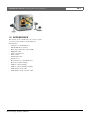
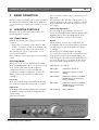
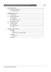
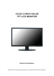
VSS7390/01T Switcher | Operating Instructions | Table of Contents
1.
2.
SAFETY PRECAUTIONS .........................................................................................................................................................2
1.1
IMPORTANT SAFEGUARDS .......................................................................................................................2
1.1.1 FCC Information ..................................................................................................................................3
1.2
INTRODUCTION .............................................................................................................................................4
1.3
ACCESSORIES ...............................................................................................................................................5
BASIC OPERATION ..................................................................................................................................................................6
2.1
OPERATOR CONTROLS .............................................................................................................................6
2.1.1 Power Switch .......................................................................................................................................6
2.1.2 Day/Night ..............................................................................................................................................6
2.1.3 Volume ...................................................................................................................................................7
2.1.4 Talk .........................................................................................................................................................7
2.1.5 Action .....................................................................................................................................................7
2.1.6 ROTARY Wheel ..................................................................................................................................7
2.1.7 Menu ......................................................................................................................................................7
2.1.8 Sequence ..............................................................................................................................................7
2.1.9 Zoom ......................................................................................................................................................7
2.1.10 Picture-In-Picture (PIP) ......................................................................................................................7
2.1.11 PIP Swap ..............................................................................................................................................7
2.2
MENU OPERATION .......................................................................................................................................7
2.2.1 History ...................................................................................................................................................8
2.2.2 Switching between playback and live ............................................................................................8
2.2.3 View settings menu ............................................................................................................................8
2.2.4 Time/Date .............................................................................................................................................8
2.2.5 System Settings ..................................................................................................................................9
2.3
ALARM FUNCTIONS .....................................................................................................................................9
2.3.1 Reset Alarm ..........................................................................................................................................9
2.3.2 Recorded Alarms ................................................................................................................................9
2.3.3 Special Alarms .................................................................................................................................. 10
2.4
DOORBELL OPERATION ......................................................................................................................... 10
Bosch Security Systems | 2003-06
EN | 1
VSS7390/01T Switcher | Operating Instructions | Chapter 1
1
SAFETY PRECAUTIONS
10
Danger
The lightning flash with arrowhead symbol,
within a triangle, is intended to alert the user to
the presence of uninstalled “dangerous voltage”
within the product's enclosure; that may be of
sufficient magnitude to constitute a risk of electric shock to persons.
Warning
The exclamation mark within a triangle is
intended to alert the user to the presence of
important operating and maintenance
(servicing) instructions in the literature
accompanying the appliance.
Caution
To reduce the risk of electricschock, do not
remove cover (or back). No user - serviceable
parts inside. Refer servicing to qualified service
personnel
1.1 IMPORTANT SAFEGUARDS
1
2
3
4
5
6
7
Read these instructions.
Keep these instructions.
Comply with all warnings.
Follow all instructions.
Do not use this equipment near water.
Clean only with dry cloth.
Do not block any ventilation openings. Install in
accordance with the manufacturer’s instructions.
8 Do not install near any heat sources such as
radiators, heat registers, stoves, or other equipment
(including amplifiers) that produce heat.
9 Do not defeat the safety purpose of the polarized or
grounding-type plug. A polarized plug has two
blades with one wider than the other. Agrounding
type plug has two blades and a third grounding
prong. Both the wide blade and the third prong are
provided for your safety. If the provided plug does
Bosch Security Systems | 2003-06
11
12
13
EN | 2
not fit into your outlet, consult an electrician for
replacement of the obsolete outlet.
Protect the power cord from being walked on or
pinched particularly at plugs, convenience
receptacles, and the point where they exit from the
equipment.
Only use attachments/accessories specified by the
manufacturer.
Unplug this equipment during lightning storms or
when unused for long periods of time.
Refer all servicing to qualified service personnel.
Servicing is required when the equipment has been
damaged in any way, such as power-supply cord or
plug is damaged, liquid has been spilled or objects
have fallen into the equipment, the equipment has
been exposed to rain or moisture, does not operate
normally, or has been dropped.
14
Warning
To reduce the risk of fire or electric shock, do
not expose this equipment to rain or moisture.
15 The equipment shall not be exposed to dripping or
splashing and that no objects filled with liquids, such
as vases, shall be placed on the equipment.
16 The back of the monitor should only be removed by
qualified maintenance and service personnel.
Ventilation
17 Keep ventilation openings free to avoid the monitor
for overheating.
18 Do not place the monitor in the immediate vicinity
of a heating source.
19 Do not install this equipment in a confined space
such as a bookcase or similar unit.
Cleaning
20 You can clean the monitor with a moist fluff-free
cloth or shammy leather cloth.
Disposal
21 This monitor contains batteries. Do not dispose of
these batteries with other solid waste. The batteries
type AA (standard penlights) are located in the
battery compartment at the bottom of your monitor.
VSS7390/01T Switcher | Operating Instructions | Chapter 1
Caution
Danger of explosion if batteries are incorrectly
replaced. Replace only with the same or equivalent type.
Remark
Bosch has a strong commitment towards the
environment. This monitor has been designed to respect
the environment as much as possible.
1.1.1 FCC Information
This equipment has been tested and found to comply
with the limits for a Class B digital device, pursuant to
part 15 of the FCC Rules. These limits are designed to
provide reasonable protection against harmful
interference in a residential installation. This equipment
generates, uses and can radiate radio frequency energy
and, if not installed and used in accordance with the
instructions, may cause harmful interference to radio
communications. However, there is no guarantee that
interference will not occur in a particular installation. If
this equipment does cause harmful interference to radio
or television reception, which can be determined by
turning the equipment off and on, the user is
encouraged to try to correct the interference by one or
more of the following measures:
• Reorient or relocate the receiving antenna.
• Increase the separation between the equipment and
receiver.
• Connect the equipment into an outlet on a circuit
different from that to which the receiver is connected.
• Consult the dealer or an experienced radio/ TV
technician for help.
Note
Any change or modification not expressly approved by
Bosch of the equipment authorization could void the
user's authority to operate the equipment.
For additional information or to speak to a
representative, please contact the Bosch Security
Systems location nearest you or visit our web site at
www.boschsecuritysystems.com
(See: Your Guide To Observation)
Bosch Security Systems | 2003-06
EN | 3
Warning
This device is intended for use in public areas
only. Surreptitious recording of oral
communications is strictly prohibited by U.S.
Federal law
VSS7390/01T Switcher | Operating Instructions | Chapter 1
1.2 INTRODUCTION
Read these instructions carefully.
For details on the installation, see Installation
Instructions supplied.
The Bosch Observation System is a sophisticated, easyto-operate observation and security system. Up to 4
cameras can be observed.
The system also supports the following features:
DAY/NIGHT
ROTARY WHEEL
By pressing just one button
you can set the system in
two different modes to
activate the day or night
alarm profile of your system.
Day/Night mode can also be
activated from an optional
Alarm/Action box.
By simply rotating and
pressing the ROTARY wheel
you can operate and control
the complete system in a
very convenient way.
SEQUENCE
Automatic camera sequence
switching, with adjustable
dwell time.
ON SCREEN DISPLAY
Operation and programming
of the system is performed
through On Screen Display
(OSD) menus. With these
easy to use menus you can
set up the system to your
own needs.
INSTALLATION WIZARD
The installation wizard
guides you through the
system menus step by step.
PRESENTATION
MODE
An advanced feature to show
promotional videos. It can be
sequenced with a live
camera image.
MOTION DETECTION
The observation cameras
automatically detect motion
within a defined motion area.
TALK FUNCTION
Built-in loudspeaker and
microphone for intercom
option.
AUDIO
Audio from the cameras is
supported and can be heard
through the system
loudspeaker.
Bosch Security Systems | 2003-06
EN | 4
ACTION FUNCTION
With the action feature you
can control external devices
connected to an external
action box, e.g. to remotely
open a door.
PIP
(Picture-In-Picture) Provides
a small camera picture within
a full screen camera picture.
ZOOM FUNCTION
Zooms the full screen live
image to twice its size.
PLAYBACK
DETECTION
When selected, it
automatically detects when
the Video Recorder is in
playback mode and will
display the recorded images.
HISTORY LIST
The history list shows all
events that have been
caused by an alarm,
doorbell, motion or a special
alarm.
AUTO ACKNOWLEDGE
When there is an alarm, the
system automatically
acknowledges the alarm and
replays the event (if event
replay is activated) after the
programmed alarm duration
has expired (can be set from
5 sec. to 15 min).
SLAVE DISPLAY
Lets you display the images
from the main monitor
(Follow) or from any camera
on the slave monitor (1-4).
VSS7390/01T Switcher | Operating Instructions | Chapter 1
1.3 ACCESSORIES
The system can be extended by one or more system
accessories. (For details see Your Guide To
Observation):
• Cameras (to a maximum of 4)
• Infra Red Remote Control
• (Time lapse) Video Recorder (VCR)
• Digital Recorder
• Cable extension box
• Intercom box
• Alarm/Action box
• Interface box
• Slave monitor (to a maximum of 2)
• Protective camera housing
• Outdoor camera housing
• Outdoor camera housing assembly
• Audio/Video (A/V) cable
• Audio/Video (A/V) extension cable
Bosch Security Systems | 2003-06
EN | 5
VSS7390/01T Switcher | Operating Instructions | Chapter 2
2
BASIC OPERATION
Operation and programming of the system is performed
through On Screen Display (OSD) menus. With these
easy to use menus you can setup the system to your own
needs.
2.1 OPERATOR CONTROLS
The functional operation of the Bosch Observation
System Switcher is as follows:
2.1.1 Power Switch
Read the instructions, before putting your system in
operation.
• Toggle the power switch located at the rear of the
monitor to switch the system on/off. A LED on the
front of the monitor indicates the system mode.
The following text appears on the monitor screen:
(x.xx = version number)
After a while the camera image appears on the monitor
screen.
2.1.2 Day/Night
The system can be set in two different modes, DAY
Mode and NIGHT Mode. These two modes are set up
in the System setup menus and allow different
configurations for day operation and night-time
operation. For example, in night-time operation, the
display picture can be switched off, alarm inputs
enabled, etc.
Day mode
In the day mode the image and sound of the monitor
are switched on and the day alarm profile is enabled.
Night mode
In the Night mode, the night alarm profile is enabled.
Availability of image and audio is configured in the
system settings.
Figure 2.1 Front Panel
Bosch Security Systems | 2003-06
EN | 6
A moon symbol is visible on the screen when you are in
night mode.
Note that if the video and audio of the monitor are set
off in the night mode, the camera continues to transmit
images and sound to the Video Recorder, slave and
aux. output.
External Day/Night Switch
You can install an optional Alarm/Action box to
activate the Day/Night Switch. When the External Day/
Night Switch is used, the Day/Night Switch on the
monitor and Remote Control are deactivated.
Remark
When switching over from day to night mode, the
actual night profile is activated when the programmed
exit delay time has expired. The LED color changes
accordingly.
An alarm generated during night mode will be
processed by the system after the entry delay time has
expired. If the system is switched from night to day
mode during the entry delay time the alarm will not be
processed. Exceptions are special alarms, like tamper
and system alarms, which will always be processed.
LED indication is as follows:
LED is OFF
Observation System off
LED is Green
Observation System is in DAY
MODE
LED is Amber
Observation System is in NIGHT
MODE with the screen display
function disabled.
LED is Red
Observation System is in NIGHT
MODE with the screen display
function enabled.
LED is blinking
Alarm indication.
VSS7390/01T Switcher | Operating Instructions | Chapter 2
EN | 7
2.1.3 Volume
2.1.9 Zoom
To change the audio volume of the cameras, intercom
boxes and Video Recorder, push the VOLUME button
(it will pop out) and rotate as required. Note that the
“beep” volume is controlled via the system setup menu.
The image will be displayed in full screen and is
digitally zoomed two times. The zoom button toggles
the zoom mode ON/OFF. If the zoom mode is active,
turning the ROTARY wheel scrolls the zooming area
through the nine pre-defined positions. A zoom symbol
is displayed. The zoom function is active for 30 secs or
until the zoom button is pressed before the 30 second
period.
2.1.4 Talk
Select the camera designated to the intercom box and
press TALK to speak through the intercom (optional).
Release the button to allow your visitor to speak to you.
The talk function is only functional in combination with
an intercom box (optional).
2.1.5 Action
Select the camera designated to the action box and press
the ACTION button to control external devices, (for
example to open a door). As long as ACTION is
pressed, a buzzer sounds, the action symbol is visible on
the monitor and the audio is set out.
Remark
The action button is only functional in combination
with an Alarm/Action box (optional).
Remark
This mode is only functional in live mode when the
respective connected camera has zoom function.
2.1.10 Picture-In-Picture (PIP)
The PIP button toggles the Picture-In-Picture ON/OFF
(only in FULL screen mode).
Keeping the PIP button pressed while turning the rotary
wheel will scroll through all connected cameras.
Keeping the PIP select button pressed while pressing the
sequence button will toggle the sequence setting of the
PIP picture ON/OFF.
The PIP position can be changed via the View Settings
menu.
2.1.6 ROTARY Wheel
During normal operation the ROTARY wheel is used to
select cameras. To acknowledge alarms, press the rotary
wheel, unless auto acknowledge is selected.
Turn the ROTARY wheel to select the previous or next
camera. Audio of the selected camera is activated.
2.1.7 Menu
After pressing the MENU button, the main menu will
be displayed. For a detailed description of the menu
operation see Chapter 2.2.
2.1.8 Sequence
The monitor displays the connected camera images in
sequence. The dwell time (sequence time) is set up in
the System setup menus.
The camera title and the sequence symbols are visible
on the screen.
Remark
This mode is only functional when the observation
system has more than one camera.
Bosch Security Systems | 2003-06
2.1.11 PIP Swap
The PIP Swap button toggles the PIP image with the full
screen image.
2.2 MENU OPERATION
Press the MENU button to display the on screen MAIN
menu. Toggle to switch ON/OFF.
Remark
If no selection is made within 30 seconds the on screen
display menu is automatically switched off.
MENU NAVIGATION
Follow the screen options and select using the
ROTARY wheel.
The ROTARY wheel controls the menu navigation as
follows:
• To scroll up/down the menu, turn the ROTARY
wheel to the required item. The highlighted text
indicates the selected menu option.
• Pressing the ROTARY wheel will either show the
available options (e.g. ON or OFF), or display the
sub-menu.
VSS7390/01T Switcher | Operating Instructions | Chapter 2
•
To decrease, increase or change the value of a
selected menu item, turn the ROTARY wheel and
acknowledge by pressing the ROTARY wheel.
• To return to the previous menu, turn the ROTARY
wheel until the previous menu title is highlighted and
acknowledge by pressing the ROTARY wheel.
After pressing the menu button the following menu will
be displayed:
MAIN MENU
HISTOR Y
SWITCH TO PLAYB ACK VIEW
VIEW SETTINGS
TIME / DATE
SYSTEM SETTINGS
>
>
>
>
>
2.2.3 View settings menu
The view settings menu enables you to change the
display on your monitor.
MAIN MENU
V I E W SE T T IN G S
P I P PO S I T I O N
H I D E TI T L E S
H I D E TI M E / D A T E
BR I G H T N E S S
C ON TR AS T
C OL O R
SHARPNESS
C AN C EL
The following view settings can be altered:
2.2.1 History
The history table shows all events that were caused by
an alarm, doorbell, motion or special alarm.
MAIN MENU
H I ST O R Y
EVENT
SOURCE
MOTION
CAMERA 1
TIM E
9 :2 3
>
DD-MM
24-01
When you select HISTORY a list with the kind of alarm
(event), the source, time and date is displayed.
A maximum of 20 events are stored in the history list
(first in, first out). You can scroll through the history list
by turning the ROTARY wheel.
Events that are recorded are:
• Alarm
• Motion
• Tamper
• Doorbell
• Fail
• Power
Alarm sources are:
• Camera - name
• Intercom (only in case of Fail)
• RCB (only in case of Fail)
• Action/Alarm box (only in case of Fail)
2.2.2 Switching between playback and live
SWITCH TO
PLAYBACK
VIEW
EN | 8
You can switch between playback
view (looking at images from a
Video Recorder) or live view
(looking at live camera images)
Bosch Security Systems | 2003-06
PIP POSITION
Set PIP (Picture-In-Picture) to top
right, bottom right, top left, bottom
left (shown by the quad image
moving within the symbol)
HIDE TITLES
Show or hide camera names in
Fullscreen, Quad and 3x3 mode.
Options are NO/YES.
HIDE TIME/
DATE
Show or hide time and date.
Options are NO/YES.
BRIGHTNESS
Adjust the screen image
brightness.
CONTRAST
Adjust the screen image contrast.
COLOR
Adjust the screen image color.
SHARPNESS
Adjust the screen image
sharpness.
HUE
(NTSC ONLY)
Adjust the screen image hue.
CANCEL
Cancel any changes made, and
return to original settings.
2.2.4 Time/Date
The time/date menu enables you to change the time
and date display on your monitor.
MAIN MENU
TIM E/ DA T E
HOUR FORMAT
TIM E
DATE FORMAT
DATE
12 H
01: 16 :01A M
D D - M M -Y Y Y Y
01- 01 - 2 0 01
VSS7390/01T Switcher | Operating Instructions | Chapter 2
EN | 9
•
To show or reset alarm, switch over from night mode
to day mode.
HOUR FORMAT
Allows you to set the hour format
(12H/24H option).
TIME
Allows you to set the system time.
DATE FORMAT
Allows you to set the date format
(DD/MM/YYYY or
MM/DD/YYYY or
YYYY/MM/DD).
DATE
Allows you to set the system date.
2.2.5 System Settings
System settings are described in the Installation
Instructions.
2.3 ALARM FUNCTIONS
The alarm function can be enabled or disabled in the
alarm profile. When motion is detected by a camera or
when an alarm is triggered by an Action/Alarm box
(optional), the alarm function is activated.
In case of an alarm:
Monitor in day mode:
• The monitor selects the respective camera input of
the Alarm/Action box.
• The blinking alarm symbol is displayed on the
monitor screen.
• The power LED starts to blink.
• The alarm output contact is activated (horn, siren or
telephone selector) and a buzzer sounds for default
30 secs (programmable range from 5 sec. to 15 min.).
• The history table is updated with the alarm event.
• Alarm event string is visible at the bottom of the
monitor screen until alarm is acknowledged. You can
manually acknowledge alarms or select auto
acknowledge.
Monitor in night mode (display ON):
Same as in day mode with the exception of:
• An alarm generated in this night mode will be
processed by the system after the entry delay time
has expired. If the system switches over from night to
day during the entry delay time the alarm will not be
processed. Exceptions are special alarms, like tamper
and system alarms, which will always be processed.
Monitor in night mode (display OFF):
Same as in night mode (display ON) with the exception
of:
• The buzzer does not sound.
Bosch Security Systems | 2003-06
Monitor in night mode (display ON AT ALARM):
Same as in night mode (display OFF) with the exception
of:
• Monitor display is switched ON if an alarm is
activated and it will display the image of the camera
that has been activated.
• If there is no user activity, the system will
automatically switch back to night mode display
OFF within 15 minutes. If there is user activity, the
user must switch the display off by pressing the Day/
Night Switch.
2.3.1 Reset Alarm
The alarm can be reset in two ways:
Manual reset:
Resets the alarm whenever the ROTARY wheel is
pressed. The monitor returns to the status before the
alarm occurred.
When the cause of the alarm has not been eliminated,
the monitor continues to display the alarm symbol.
When the ROTARY wheel is not pressed during an
alarm, the monitor automatically acknowledges the
alarm after default 30 secs (programmable range from 5
sec. to 15 min.). The monitor returns to the status before
the alarm occurred. The blinking alarm message is displayed until the ROTARY wheel is pressed.
Auto acknowledge:
When there is an alarm, the system automatically
acknowledges the alarm after the programmed alarm
duration has expired (can be set from 5 sec. to 15 min).
Note
If the display is in sequence mode during an alarm, it
automatically returns to sequence mode, starting with
the next image after the alarm image.
2.3.2 Recorded Alarms
During playback the recorded alarms will be visible.
Should an alarm be received during playback, the
system will return to live mode.
VSS7390/01T Switcher | Operating Instructions | Chapter 2
2.3.3 Special Alarms
A special alarm is given in case of:
TAMPER
An accessory housing has been
opened.
FAIL
A failure in the system
communication to accessories or
camera has been found.
• Press the ROTARY wheel to stop the alarm.
Detailed information of the alarm is stored in the history
table.
2.4 DOORBELL OPERATION
If the doorbell button on the intercom box is pressed
the following functions are activated:
• The monitor automatically selects the camera input
to which the intercom box is connected
• The blinking bell symbol is displayed on the monitor
screen as long as the doorbell button is pressed
• The history table is updated.
Remark
The doorbell function is only functional in combination
with an intercom box (option). If ‘remote’ option is
selected, the doorbell can also trigger the alarm output
contact of the system monitor.
Bosch Security Systems | 2003-06
EN | 10