1
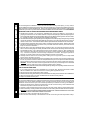
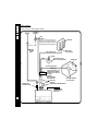
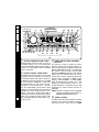
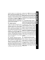
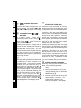
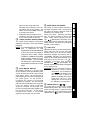
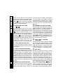
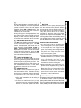
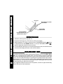
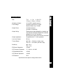
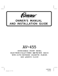
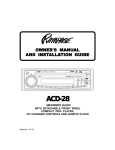
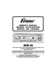
OWNER'S MANUAL
ROCK
EQ
TRACK
CLAS
POP
RND
SCAN
RPT
ACD-84
AM/FM/MPX RADIO WITH MOTORIZE
FOLD-DOWN DETACHABLE FRONT PANEL,
COMPACT DISC PLAYER,
CD CHANGER CONTROLS,
WIRELESS REMOTE CONTROL
AND QUARTZ CLOCK
INSTRUC
T IONS
INSTALL
ALLA
INSTRUCT
ALL
ATAION
T IONS
INST
ALL
T IONINSTRUC
INSTALL
ALLA
INSTRUCT
INST
INSTALLATION INSTRUCTIONS
This unit is designed for installation in cars, trucks, and vans with an existing radio opening. In many cases, a
special installation kit will be required to mount the radio to the dashboard. These kits are available at electronics
supply stores and car stereo specialist shops. Always check the kit application before purchasing to make sure the
kit works with your vehicle. If you need a kit but cannot find it available, call our toll-free “HELP” line at 1-800-645-4994.
UNIVERSAL INSTALLATION PROCEDURE USING MOUNTING SLEEVE
1. Activate panel fold-down, and remove the detachable front panel, if it is attached to the chassis, by
grasping the release latch on the middle underside of the panel and pulling the panel assembly straight out.
The mounting plate will return to the upright position within 3 seconds. Slide the mounting sleeve off of the chassis.
If it is locked into position, use the removal tools (supplied) to disengage it.
2. Check the dashboard opening size by sliding the mounting sleeve into it. If the opening is not large enough, carefully
cut or file as necessary until the sleeve easily slides into the opening. Do not force the sleeve into the opening or
cause it to bend or bow. Check that there will be sufficient space behind the dashboard for the radio chassis.
3. Locate the series of bend tabs along the top, bottom, and sides of the mounting sleeve. With the sleeve fully
inserted into the dashboard opening, bend as many of the tabs outward as necessary so that the sleeve is
firmly secured to the dashboard.
4. Place the radio in front of the dashboard opening so that the wiring can be brought through the mounting
sleeve. Follow the wiring diagram carefully and make certain all connections of the wiring harness are secure
and insulated with wire nuts or electrical tape to insure proper operation of the unit. After completing the
wiring connections, attach the front panel and turn the unit on to confirm operation (ignition switch must be
“on”). If unit does not operate, re-check all wiring until problem is corrected. Once proper operation is
achieved, turn off the ignition switch and proceed with final mounting of the chassis.
5. Carefully slide the radio into the mounting sleeve making sure it is right-side-up until it is fully seated
and the spring clips lock it into place.
6. Attach one end of the perforated support strap (supplied) to the screw stud on the rear of the chassis using
the hex nut provided. Fasten the other end of the perforated strap to a secure part of the dashboard either
above or below the radio using the screw and hex nut provided. Bend the strap to position it as necessary.
CAUTION: The rear of the radio must be supported with the strap to prevent damage to the dashboard
from the weight of the radio or improper operation due to vibration.
7. Re-attach the front panel to the chassis and test radio operation by referring to the Operating Instructions for the unit.
INSTALLATION USING KITS
1. If your vehicle requires the use of an installation kit to mount this radio, follow the instructions included
with the installation kit to attach the radio to the mounting plate supplied with the kit.
2. Wire and test the radio as described in Step 4 above.
3. Install the radio/mounting plate assembly to the sub-dashboard according to the instructions of the installation kit.
4. Attach the support strap to the radio and dashboard as described in Step 6 above.
5. Replace the dashboard trim panel.
ISO INSTALLATION PROCEDURE
1
This unit has threaded holes in the chassis side panels which may be used with the original factory mounting
brackets of some Toyota, Nissan, Mitsubishi, Isuzu, Hyundai and Honda vehicles to mount the radio to the
dashboard. Please consult with your local car stereo specialist shop for assistance on this type of installation.
1. Remove the existing factory radio from its dashboard or center console mounting. Save all hardware and
brackets as they will be used to mount the new radio.
2. Carefully un-snap the plastic frame from the front of the new radio chassis. Remove and discard the frame.
3. Remove the factory mounting brackets and hardware from the existing radio and attach them to the new radio.
CAUTION: DO NOT EXCEED M5 X 8 MM MAXIMUM SCREW SIZE. LONGER SCREWS MAY TOUCH AND
DAMAGE COMPONENTS INSIDE THE CHASSIS.
4. Wire the new radio to the vehicle as per step 4 above.
5. Mount the new radio assembly to the dashboard or center console using the reverse procedure of step 1.
DAY
MON. - FRI.
SATURDAY
TIME ZONE
MOUNTAIN
CENTRAL
7:30AM - 6PM
6:30AM - 5PM
8AM - 4PM
7AM - 3PM
PACIFIC
5:30AM - 4PM
6AM - 2PM
EASTERN
8:30AM - 7PM
9AM - 5PM
UNIVERSAL INSTALLATION USING MOUNTING SLEEVE
NUT (5MM)
PERFORATED STRAP
FASTEN THIS END TO SCREW
STUD ON REAR OF CHASSIS
EXISTING DASH OPENING
FILE EDGES TO FIT IF NECESSARY - DO NOT OVERFILE
NOTE: IF DASH IS SOLID, USE REAR SIDE (WITHOUT THE LIP) OF
MOUNTING SLEEVE AS A TEMPLATE & CUT OPENING
BEND TOP
TABS UPWARD
SCREW
(5MM)
INST
ALL
AT ION INSTRUC
INSTALL
ALLA
INSTRUCTT IONS
TOLL-FREE INSTALLATION ASSISTANCE
The installation and wiring connections for this unit are so simple, we doubt you'll need our help, but, if you do,
we're here to help you. Just call our toll-free telephone assistance line at 1-800-645-4994 during the days and
hours shown (U.S.A. and Canada only).
BEND BOTTOM
TABS DOWNWARD
RADIO
SCREW STUD
NUT (5MM)
MOUNTING SLEEVE
FASTEN THIS END TO SECURE PART OF DASHBOARD.
DRILL HOLE IF NECESSARY.
REMOVAL TOOLS
CAUTION:
FOR PROPER OPERATION OF THE CD PLAYER, THE CHASSIS
MUST BE MOUNTED WITHIN 20° OF HORIZONTAL. MAKE SURE
THE UNIT IS MOUNTED WITHIN THIS LIMITATION.
20° MAX.
SIDE VIEW
OF
FRONT PANEL
CHASSIS
FOLD-DOWN
DETACHABLE
FRONT PANEL
ISO INSTALLATION
TYPICAL INSTALLATION
REMOVE THE PLASTIC FRAME FROM THE FRONT OF
THE CHASSIS BY CAREFULLY UN-SNAPPING IT.
UN-SNAP AT 2 PLACES
EACH ON TOP AND BOTTOM
MAXIMUM
SCREW SIZE
M5 x 8
PLASTIC FRAME
FACTORY MOUNTING
BRACKETS
MAXIMUM
SCREW SIZE
M5 x 8
2
RRAADIO WIRING
SPE
A K ER WIRING
SPEA
RADIO WIRING
REFER TO PAGE 4 FOR SPEAKER WIRING
AUTOMATIC
ANTENNA
ANTENNA
BLUE
IMPORTANT
THE BLUE WIRE CAN BE USED TO
REMOTELY ACTIVATE AN AUTOMATIC
ANTENNA OR AN EXTERNAL AMPLIFIER
(SEE ANTENNA OR AMPLIFIER MANUAL)
EXISTING
ANTENNA
CABLE
RED (0.5 AMP. FUSE)
FUSEBLOCK
“RADIO” FUSE
+12V ACCESSORY
SCREW
BLACK
METAL PART OF DASH
(DRILL HOLE IF NECESSARY)
CAR BATTERY
YELLOW (15 AMP. FUSE)
FILTER/FUSE
BOX
IMPORTANT
YELLOW WIRE MUST BE
CONNECTED AS SHOWN OR
RADIO WILL NOT OPERATE
PROPERLY
CONTAINS:
ONE 0.5 AMP FUSE
ONE 15 AMP FUSE
4-PIN PLUGS
ANTENNA LEAD
ON REAR OF RADIO
9 PIN PLUG
(SEE PAGE 4FOR SPEAKER WIRING)
CD CHANGER LEAD
ON REAR OF RADIO
(SEE PAGE 4)
3
POSITIVE (+) TERMINAL
12 VOLT BATTERY
REFER TO PAGE 3
FOR RADIO WIRING
WARNING!
l THE AMPLIFIERS IN THIS RADIO ARE ONLY DESIGNED FOR USE WITH 4 SPEAKERS.
l NEVER COMBINE (BRIDGE) OUTPUTS FOR USE WITH 2 SPEAKERS.
l NEVER GROUND NEGATIVE SPEAKER LEADS TO CHASSIS GROUND.
l FAILURE TO WIRE EXACTLY AS SHOWN BELOW MAY CAUSE ELECTRICAL
NOTE:
RCA LINE OUT JACKS
FOR USE WITH OPTIONAL
EXTERNAL AMPLIFIERS
THIS RADIO WILL CONTROL RAMPAGE CD
CHANGER MODELS. CHECK WITH YOUR RAMPAGE AUDIOVOX CAR STEREO SPECIALIST OR
CALL 1-800-645-4994 FOR RECOMMENDATIONS
OF OTHER MODELS THAT WILL WORK WITH YOUR
RADIO.
OPTIONAL CD CHANGER
RADIO
SPE
A K ER WIRING
SPEA
SPEAKER WIRING
6
CO M P AC T
DIN CABLE
(SUPPLIED WITH CD
CHANGER)
CD CHANGER LEAD
ON REAR OF RADIO
9-PIN PLUGS
4-PIN PLUGS
SEE PAGE 3 FOR
RADIO WIRING
LEFT FRONT SPEAKER
RIGHT FRONT SPEAKER
GRAY w/BLACK STRIPE
WHITE w/BLACK STRIPE
WHITE
GRAY
GREEN
VIOLET
GREEN w/BLACK STRIPE
VIOLET w/BLACK STRIPE
HELP!
Monday - Friday 8:30am - 7:00pm Eastern
Saturday
9:00am - 5:00pm Eastern
LEFT REAR SPEAKER
1-800-645-4994
4
RIGHT REAR SPEAKER
OPER AT ING INSTRUC
INSTRUCTT IONS
3, 4, 5, 6, 7
2
17, 28, 29
(BEHIND PANEL)
14
15
26
27
30
8
ROCK
9
EQ
25
TRACK
CLAS
RND
POP
SCAN
RPT
11
10, 18, 19, 34, 35 31 20 21
36
22
37
23
38
13
1
ON-OFF POWER BUTTON ( PWR )
Press this button to turn the unit on or off. If
the ignition switch is “on”, the unit will also
turn on automatically when a compact disc is
inserted, or if the MODE switch or BAND
switch is pressed.
2
24
33
12
16
32
1
3
AUDIO SELECT (SEL) CONTROL
BUTTON
This button is used to select the audio
function (volume, bass, treble, balance, or
fade) whose setting is adjusted using the
AUDIO CONTROL knob
. Pressing the
SEL button once will set the unit for bass
adjustment (BAS will appear on the display
panel) and an audible beep will occur.
Pressing the button additional times will
select treble adjustment (TRE on the
display), balance (BAL), or fader (FAD),
each accompanied by a beep tone. The
display will automatically return to the
normal indication 5 seconds after the last
adjustment or when another function is
activated.
NOTE: Bass and Treble cannot be adjusted
while the Equalizer function
is in
ROCK, CLAS or POP mode.
2
AUDIO CONTROL UP/DN KNOB
To increase the volume level, turn the knob
clockwise in the UP direction. The volume
will increase and the level will be shown on
the display panel from a minimum of VOL
00 to a maximum of VOL 39. To decrease
the volume level, turn the knob counterclockwise in the DN direction. The display will automatically return to the normal
indication 5 seconds after the last volume
adjustment or when another function is activated. This control knob is also used in
conjunction with the AUDIO SELECT (SEL)
button
to adjust the bass, treble, balBASS CONTROL
,
ance and fader levels as described in
To
adjust
the bass level (equalizer function
,
and
.
inactive), first select the Bass mode by
so the BAS
pressing the SEL button
5 56
3
cu
7
4
4
3
2
display panel from BAL L16 (full left) to BAL
R16 (full right). When the volume level
between the left and right speakers is equal,
BAL 00 will be shown on the display panel.
The display will automatically return to the
normal indication 5 seconds after the last
adjustment or when another function is
activated.
7
TREBLE CONTROL
To adjust the treble level (equalizer function
inactive), first select the Treble mode by
so the TRE
pressing the SEL button
indication appears on the display panel.
Within 5 seconds of choosing the Treble
mode, rotate the AUDIO CONTROL knob
in the DN direction to decrease the treble
response or the UP direction to increase it
as desired. The level will be shown on the
display panel from a minimum TRE -12 to a
maximum of TRE +12 (TRE 00 indicates flat
response). The display will automatically
return to the normal indication 5 seconds
after the last adjustment or when another
function is activated.
FRONT/REAR FADER CONTROL
To adjust the front-rear speaker balance, first
select the Fader mode by pressing the SEL
so the FAD indication appears on
button
the display panel. Within 5 seconds of
choosing the Fader mode, rotate the
in the DN
AUDIO CONTROL button
direction to adjust the front-rear speaker
balance to the rear speakers or the UP
direction to adjust it to the front speakers.
The fader position will be shown on the
display panel from FAD R16 (full rear) to FAD
F16 (full front). When the level between the
front and rear speakers is equal, FAD 00
will be shown on the display panel. The
display will automatically return to the
normal indication 5 seconds after the last
adjustment or when another function is
activated.
LEFT/RIGHT BALANCE CONTROL
To adjust the left-right speaker balance, first
select the Balance mode by pressing the
so the BAL indication
SEL button
appears on the display panel. Within 5
seconds of choosing the Balance mode,
in the
rotate the AUDIO CONTROL knob
DN direction to adjust the stereo balance to
the left channel speakers or the UP direction
to adjust it to the right channel speakers.
The balance position will be shown on the
LOUDNESS CONTOUR (LOUD)
When listening to music at low volume
levels, this feature will boost the bass and
treble ranges to compensate for the
characteristics of human hearing. Press the
button momentarily to activate this feature;
the LOUD indication will appear on the
display panel. Pressing the button again
momentarily will deactivate the feature (the
LOUD indication will disappear from the
display panel).
5
3
2
6
3
2
3
OPER AT ING INSTRUC
INSTRUCTT IONS
indication appears on the display panel.
Within 5 seconds of choosing the Bass
mode, rotate the AUDIO CONTROL knob
in the DN direction to decrease the bass
response, or in the UP direction to increase
it as desired. The level will be shown on the
display panel from a minimum of BAS -12
to a maximum of BAS +12 (BAS 00
indicates flat response). The display will
automatically return to the normal indication
5 seconds after the last adjustment or when
another function is activated.
2
8
6
OPER AT ING INSTRUC
INSTRUCTT IONS
9
AM/FM CHANNEL SELECTOR
(BAND)
Each time this button is pressed, the radio
band is changed. The indication AM1, AM2,
FM1, FM2 or FM3 will appear on the display
panel according to your selection.
bl
- )
TUNE/SKIP/TRACK (+
/
BUTTONS
To manually select a radio station,
momematrily press the Up Tuning ( +
)
button to advance the unit higher, or the
- ) button to tune lower
Down Tuning (
within the selected band.
Pressing either button for longer than 0.5
second and then releasing will activate the
Automatic Skip Tuning function. The radio
will skip over weaker stations in the selected
direction and stop at the strongest frequency.
The Seek function can be stopped by
pressing the button again or by activating any
other tuning function.
bm
bn
PRE-SET SCAN (PS)
AUTO-STORE TUNING (AS)
Press this button momentarily to scan the
stations pre-set into the six memories of the
current band in use. The unit will stop at each
pre-set station for 5 seconds before
continuing to the next pre-set station (the
pre-set number on the display panel will flash
during Pre-Set Scan operation). Press the
button again momentarily to stop Pre-Set
Scan operation and remain on the selected
frequency. If no buttons are pressed during
the scan, the unit will return to the original
station before the scan started.
Pressing and holding the button for longer
than 2 seconds will activate the Auto-Store
Tuning feature which will automatically scan
and enter up to 6 stations into the pre-set
memories on the band in use. If you have
already set the pre-set memories to your
favorite stations, activating the Auto-Store
Tuning feature will erase those stations and
enter the new ones. This feature is most
useful when traveling in a new area where
you are not familiar with the local stations.
FM MONO/STEREO BUTTON (MONO)
During FM radio operation, this button is used
to select mono or stereo reception of the
STATION PRE-SET MEMORIES
broadcast signal. Under normal reception
To set any of the 6 pre-set memories in each
conditions, the unit should be left in the
band, use the following procedure:
stereo mode as indicated by the ST
1. Turn the radio on and select the desired
indication on the display panel when tuned
band.
to an FM stereo signal. If the stereo signal
2. Select the first station to be pre-set
is too noisy for comfortable listening, press
using the Manual TUNE or Automatic
the FM Mono/Stereo Selector button to
.
SEEK Controls
switch to mono reception (the ST
3.
Press
the
pre-set
button
to be set and
indication will disappear from the display
continue to hold it in for
panel). To return to stereo reception mode,
approximately 2 seconds. The
press the button again so that the ST
preset number, followed by CH
indication appears in the display panel.
(channel) will appear on the display
bo
bl
7
bp
functions.
NOTE: It is a characteristic of LCD panels
that, if subjected to cold
temperatures for an extended period
of time, they may take longer to
illuminate than under normal
conditions. In addition, the visibility
of the numbers on the LCD may
slightly decrease. The LCD readout will return to normal when the
temperature increases to a normal
range.
bq
LEVEL METER DISPLAY
This display consists of a five-bar graph
which provides a visual representation of the
volume level and the left and right channel
audio signal levels. The volume level is
represented by the two outer bar graphs and
the center graph. As the volume is
increased, the number of illuminated
segments will increase. The left and right
channels are represented by the respective
inner bar graphs whose illuminated
segments increase and decrease as a
function of the signal strength applied to the
left and right channels. As the signal
increases, the number of illuminated
segments will increase and vice-versa.
br
MODE SELECTOR (MODE)
This button is used to select the radio or
CD player playback mode. Each press of
the button will select a different mode as
indicated on the display panel.
During CD player operation, this button
may be used to change to radio or CD
player mode without ejecting the disc.
The
IN indication will remain on the
display panel. When returning to CD player
mode, disc play will resume from the point
at which it was stopped.
bs
DISC SLOT
With the front panel in the fold-down position,
gently insert the disc into the slot (label
surface facing up) until the soft-loading
mechanism engages and pulls the disc in.
The LOAD indication will momentarily
appear on the display panel followed by the
)
total playing time of the disc. The (
indication illuminates and becomes
animated, the
IN symbol lights, and
the track number and elapsed time will appear
on the display panel.
CAUTION: This unit is designed for play of
standard 5" (12cm) compact
discs ONLY. Do not attempt to
use 3" (8cm) CD-Singles in this
unit, either with or without an
adapter, as damage to the player
and/or disc can occur. Such
damage will not be covered by
the Warranty on this product.
OPER AT ING INSTRUC
INSTRUCTT IONS
panel and two beeps will sound,
indicating that the station is now set
into that pre-set memory position. The
station can now be recalled at any time
by pressing that button.
4. Repeat the above procedure for the
remaining 5 pre-sets on that band and
for the other 4 bands on the unit.
LIQUID CRYSTAL DISPLAY PANEL
The Liquid Crystal Display (LCD) panel
displays the frequency, time, and activated
bt
TRACK SELECT ( +
/
-)
The Track Select function of the TUNE/
SEEK/TRACK buttons are used to quickly
access the beginning of a particular track
when a disc is in play. Each time the Forward
TRACK Select ( +
) side of the button is
8
OPER AT ING INSTRUC
INSTRUCTT IONS
pressed, the next higher track number will
be selected as shown on the display panel.
Similarly, each time the Backward TRACK
Select (
- ) side of the button is pressed,
the next lower track number will be selected
as shown on the display panel.
track will continue to repeat until the button
is pressed again and the RPT indication
disappears from the display panel. Repeat
Play mode will also be canceled by activating
or Random Play
the Track Scan
functions.
CUE/REVIEW FUNCTIONS
-)
(+
/
High-speed audible search to any section
of the disc can be made by the Cue and
Review functions. Press and hold the Cue
(+
) button to advance rapidly in the
forward direction (the advancing disc playing
time will be shown on the display panel),or
the Review (
- ) button to advance rapidly
in the backward direction (the decreasing
disc playing time will be shown on the
display panel). During either function, the
elapsed time within each track will
automatically be shown on the display panel.
RANDOM PLAY SELECTOR (RND)
During disc play, press this button to play the
tracks on the disc in a random shuffled order
(RND will appear on the display panel). In
Random Play mode, the TRACK Select function
will also select tracks in the random order instead
of the normal progression. The Random Play
mode can be canceled by pressing the button
again (RND indication will disappear from the
display panel) or by activating the Repeat Play
or Track Scan
functions.
bu
cm
co
cn
cm
cp
DISC SELECT UP/DOWN
(D.UP/D.DN)
These buttons are used to select the desired
disc for play during changer operation. To adTRACK ONE POSITION (TOP)
The Track One Position function is used to vance to a higher number disc, press the D.UP
quickly return to the beginning of the current CD button, and to return to a lower number disc,
press the D.DN button. The number of the disc
in play (Track 1).
in play will be shown on the display panel.
TRACK SCAN SELECTOR (SCN)
DISC EJECT
During disc play, press this button to play the
Disc
play
is stopped and the disc is ejected
first 10 seconds of each track on the disc
(SCAN) will appear on the display panel). when the EJECT button is pressed. It is
When a desired track is reached, press the necessary to first open the panel before
SCN button again to cancel the function ejecting the disc. Radio or CD changer operation
(SCAN will disappear from the display panel) will automatically resume depending on which
and play of the selected track will continue. mode was in operation prior to disc play. If
Scan mode will also be canceled by activating the disc is not removed from the unit within 15
seconds of being ejected, it will automatically
, or Random Play
the Repeat Play
be re-loaded into the unit to prevent it from
functions.
being accidentally damaged (
IN will
REPEAT PLAY SELECTOR (RPT)
appear on the display panel to indicate that
During disc play, press this button to repeat a disc is loaded in the player). Play of the
the play of the selected track (RPT will disc can be resumed by using the MODE
appear on the display panel). Play of the button
to choose theCD player function.
cl
cm
9
co
cn
cq
cn
co
br
TIME/FREQUENCY SELECTOR (T/F)
During radio operation, press this button to
call the time display on the incorporated
quartz clock. The current time will appear
together with an AM or PM indication. The
display will return to the radio frequency
indication after 5 seconds.
During CD player or changer operation, the
first press of the button will call the time
display. In either case, the display will return
to the disc track indication after 5 seconds.
cs
dl
FRONT PANEL OPEN/CLOSE
BUTTON
This button is used to open (fold down) and
close the motorized front panel. To detach
the front panel, press the button so that the
panel folds down to the lowered position.
Grasp the release latch on the middle
underside of the panel and pull the panel
straight off of the panel mounting plate. The
mounting plate will then automatically return
to the upright position within 3 seconds, and
the theft-deterrent LED will begin to flash.
EQUALIZER BUTTON (EQ)
The EQ button applies preset sound effects NOTES ON USE OF FRONT PANEL:
to the unit’s audio output signal. The EQ 1. The front panel must be reinstalled with
button, when pressed, will activate one of
the mounting plate in the upright position.
three operating modes (ROCK, CLAS, or
To accomplish this, first engage the left
POP). When the EQ function is active, as
side of the panel into the mounting plate
displayed on the panel, the bass and treble
guide; then carefully press the right side of
levels cannot be changed. When the EQ
the panel until it snaps into place in the
function is not active, the unit returns to the
right mounting plate guide.
user set bass and treble levels.
2.To verify correct panel installation, press the
ct
THEFT-DETERRENT LED
Located on the chassis behind the front
panel, a light-emitting diode (LED) will flash
when the panel is physically removed. The
flashing light serves as a visual warning to
the would-be thief that the unit has been
disabled by removal of the front panel.
cu
RESET BUTTON
The RESET button is located to the right of
the theft deterrent LED. The reset circuitry
should only be activated under the following
circumstances as it will erase the time
and pre-set memories:
1.Upon initial installation after all wiring is
completed.
2.If there is a malfunction of any of the
switches on the unit, pressing the RESET
button may clear the system and return
to normal operation.
INSTRUCTT IONS
OPER AT ING INSTRUC
cr
OPEN/CLOSE button to swing the panel
assembly down, and then up into position
until it locks easily into place. If any
resistance is encountered, re-check panel
orientation in chassis mounting plate.
3. When taking the front panel with you,
please use the supplied carrying case to
protect the panel from dirt and damage.
Make sure there is no dust or dirt on the
electrical terminals on the back of the
panel as this could cause intermittent
operation or other malfunctions.
dm REMOTE SENSOR
The sensor to detect the infrared signal from
the wireless remote control is located
adjacent to the lower left corner of the front
panel. For optimum operation of the remote
control, always aim the control at this area.
10
OPER AT ING INSTRUC
OR CODES
INSTRUCTT IONS / SET T ING THE CLOCK / ERR
ERROR
DISC SLOT
MOTORIZED FOLD-DOWN
FRONT PANEL
FRONT PANEL
RELEASE TAB
THEFT-DETERRENT
LED AND RESET BUTTON
(BEHIND FRONT PANEL)
SET T ING THE CLOCK
1. Switch the vehicle ignition and radio “on”.
2. Press the Time/Frequency (T/F) button to call the time display.
3. While holding the T/F button in, press the Down TUNE/SEEK/TRACK ( - ) button
to adjust the hours and AM/PM indication, or the Up TUNE/SEEK/TRACK ( +
)
button to adjust the minutes to the correct time.
4. Five seconds after the last hour or minute adjustment is made, the time will be set in
the unit and the display will return to the normal indication.
CD PL
AYER ERR
OR CODES
PLA
ERROR
If a problem should develop while operating the CD player, an error code (ER-1, ER-2,
ER-3, etc.) may appear on the display panel. This can indicate a number of problems
with the unit, including a mechanical error or an error in the microprocessor control of the
player. If an error code should appear, try ejecting and re-loading the disc into the player.
While the disc is out of the unit, make sure it is clean, undamaged, and loaded correctly
(label surface up). You may also try activating the RESET button on the unit, but this
will also erase the time and pre-set memories.
If the suggested measures do not solve the problem, contact an approved warranty
station near you for further assistance.
cu
11
Size:
7" W
x 2" H x 6-5/16" D
178 mm x 50 mm x 160 mm
Operating Voltage:
12 volts DC, negative ground
Fuse Ratings:
Constant (Yellow wire): 15 AMP.
Switched (Red wire): 0.5 AMP.
Output Power:
160 watts maximum
(40 watts x 4 channels)
Output Wiring:
Floating-ground type designed for 4 speaker use.
Front and rear channels CANNOT be combined
(bridged) for use with 2 speakers.
RCA low-level outputs (front and rear channels).
Output Impedance:
Compatible with 4 – 8 ohm speakers.
Low-Level Output:
500 mv.
Tuning Range:
AM: 530 – 1,720 kHz. (10 kHz. step)
FM: 87.5 – 107.9 MHz. (200 kHz. step)
Sensitivity:
AM: 20 uv.
FM: 1.5 uv.
FM Stereo Separation:
>20 dB
CD Frequency Response:
17 – 20 kHz. +0/-3 dB
CD Signal/Noise Ratio:
>65 dB
CD Channel Separation:
>60 dB
CD Distortion:
0.2%
SPECIFICATT IONS
SPECIFICA
SPECIFICATIONS
*Specifications are subject to change without notice.
12
CD CH
A NGER CONTR
OL
S
CHA
CONTROL
OLS
CD CH
A NGER CONTR
OL
S
CHA
CONTROL
OLS
Built into this radio are controls to operate
an optional CD changer. Please check with
your Rampage/Audiovox car stereo
specialist or call 1-800-645-4994 for
recommendations of the models that will
work with this radio.
Adjustment of the audio functions (volume,
tone, balance, and fader) for the CD changer
operate in the same manner as they do for
radio play. The following controls will operate
the CD changer when it is installed and
connected to this radio. Refer to the owner’s
manual included with the CD changer for
instructions on the installation and correct
loading and use of the CD magazine.
next higher track number will be selected
as shown on the display panel. Similarly,
each time the Backward Track Select ( -)
button is pressed, the next lower track
number will be selected as shown on the
display panel.
dq CUE/REVIEW FUNCTIONS
-)
(+
/
High-speed audible search to any section of
the disc can be made by the Cue and Review
functions. Repeated press the Cue ( + )
side of the button to advance rapidly in the
forward direction (disc play symbol rotation
on the display panel will stop) or the Review
- ) side of the button to advance rapidly
(
in the backward direction.
dn CD
CHANGER MODE SELECTOR
dr TRACK/DISC
SCAN SELECTOR
(MODE)
(SCN)
During radio or CD play, press this button to
select operation of the CD changer as shown
by CDC on the display panel. Disc play will
begin and the DISC and track number will
be shown on the display panel. When the
magazine is loaded into the changer, play
will begin from the first track of the first disc
in the magazine.
do DISC SELECT (D.UP/D.DN)
These buttons are used to select the desired
disc for play. To advance to a higher number
disc, press the D.UP button. To return to a
lower number disc, press the D.DN button.
The number of the disc in play will be shown
on the display panel.
dp TRACK SELECT (
13
/
-)
+
The Track Select functions are used to
quickly access the beginning of a particular
track. Each time the Forward Track Select
(+
) side of the button is pressed, the
When the SCN button is pressed, the SCAN
indication will appear on the display panel,
and the first 10 seconds of each track on
the disc will be played in order. When a
desired track is reached, press the SCN
button twice and play of the selected track
will continue (SCAN will disappear from the
display panel). The Track Scan mode will
also be canceled by activating the Repeat
or Random Play function.
When the Scan button is pressed twice
the DISC and SCN indications will appear
on the display panel and the first 10 seconds
of the first track on each disc in the magazine
will be played. When a desired disc track is
reached, press the SCN button again and
play of the selected disc will continue (DISC
and SCAN will disappear from the display
panel). The Disc Scan mode will also be
ds
dt
CD CH
A NGER ERR
OR CODES
CHA
ERROR
If a problem should develop while operating the CD changer, the following error codes may
appear on the display panel.
ER-1: Indicates that there is no magazine loaded in the CD changer.
ER-2: Indicates a problem with the magazine eject function.
ER-3: Indicates an error in the disc loading function.
ER-4: Indicates an error in the disc un-loading function.
ER-5: Indicates an error in the magazine position.
ER-6: Indicates an error in the laser pick-up position.
ER-7: Indicates an error in the laser focus on the disc.
In any of the above situations, try ejecting the CD magazine from the changer and make
sure the discs are clean, undamaged, and loaded correctly (refer to the Owner’s Manual
of the CD changer). Re-load the magazine and check for proper operation. You may also
try activating the RESET button on the unit, but this will also erase the time and pre-set
memories.
If the suggested measures do not solve the problem, contact an approved warranty station
near you for further assistance.
CD CH
A NGER CONTR
OL
S / CD CH
A NGER ERR
OR CODES
CHA
CONTROL
OLS
CHA
ERROR
canceled by activating the Repeat or Random indication will appear on the display panel
and the tracks on the disc will be played in
Play function.
a random, shuffled order. The Track Select
DISC/TRACK REPEAT PLAY (RPT)
button will also select tracks in the shuffled
When the RPT button is pressed, the RPT order instead of the normal progression. The
indication will appear on the display panel Random Track mode can be canceled by
and play of the selected track will be pressing the RND button twice or by
continually repeated until the Track Repeat activating the Scan or Repeat Play
mode is canceled by pressing the RPT functions.
button twice or by activating the Scan or When the RND button is pressed twice,
the DISC and RND indications will appear
Random Play functions.
When the RPT button is pressed twice, the on the display panel and the discs in the
DISC and RPT indications will appear on magazine will be played in a random, shuffled
the display panel and play of the selected order, as well as the tracks on each disc.
disc will be continually repeated until the After playing a track selected at random from
Disc Repeat mode is canceled by pressing a disc in the magazine, the unit will select
another disc at random and play all the
the RPT button again or by activating the
tracks on it in a random shuffled order. This
Scan or Random Play functions.
will continue from disc-to-disc until the
DISC/TRACK RANDOM PLAY (RND) Random Disc mode is canceled by pressing
When the RND button is pressed, the RND the RND button again or by activating the
Scan or Repeat Play functions.
cu
14
REMO
TE CONTR
OL OPER AT ION
REMOTE
CONTROL
WIRELESS REMOTE
CONTROL OPERATION
The wireless remote control supplied with
this model is capable of operating most of
the features of the unit from a remote location. Each button on the remote control functions in the same way as the referenced
button on the main unit. For optimal operation of the remote control, always aim it toward the Remote Sensor on the front panel
of the main unit.
dm
1 PWR ON/OFF ( ) – See Main Unit 1
2 VOLUME
(LEVEL) CONTROL – See
Main Unit 2 3 4, 5, 6 and 7
,
,
6 RADIO
PRE-SET MEMORY 1-6
- See Main Unit bo.
7 DISC
UP SELECT (DISC +)
- See Main Unit cp .
8 DISC
DOWN SELECT (DISC -)
- See Main Unit cp .
9 TRACK/DISC
REPEAT (RPT)
- See Main Unit cn and ds.
bl TRACK/DISC
RANDOM (RND)
- See Main Unit co and dt.
bm TRACK/DISC
TRACK ONE POSITION
(TOP) - See Main Unit cl.
except press VOL to increase level,
and press VOL to decrease level.
3 SELECT
BUTTON (SEL) - See Main
Unit 3, 4, 5, 6 and 7
4 AM/FM
BAND SELECTOR (BND) - See
Main Unit 9
5 MANUAL
UP/DOWN TUNE – See
Main Unit bl except press
to
1
13
2
15
3
.
4
5
.
to
11
AUTOMATIC SEEK TUNING – See
Main Unit except press
to Seek
upward, press
to Seek downward.
6
increase frequency, press
decrease frequency.
bl
CD TRACK SELECT – See Main Unit
and
except press
to select a
higher track number, press
- to
select a lower track number.
bt
15
12
dp
9
10
bu
CD CUE/REVIEW – See Main Unit
and
except press
for Cue
function, and press
for Review
function.
dq
14
7
16
8
operation.
CARE AND MAINTENANCE
The radio section of your new sound system does not require any maintenance. We
recommend you keep this manual for reference on the many features found in this unit
as well as how to set the clock.
The compact disc player section also requires no routine maintenance, but proper
understanding of its use and handling will help you obtain maximum enjoyment of its
capabilities. The following points should be observed:
l When cleaning the interior of the vehicle, do not get water or cleaning fluids on the
unit.
l The CD player is a precision instrument and will not operate properly in extreme hot
or cold. In case of such conditions, wait until the interior temperature of the vehicle
reaches a normal temperature before using the player.
l If the temperature inside the player gets too hot, a protective circuit will automatically
stop play of the disc. In this case, allow the unit to cool off before operating the player
again.
l Never insert anything other than a 5" (12 cm) compact disc into the player as the
mechanism can be damaged by foreign objects.
REMO
TE CONTR
OL OPER AT ION / CA
RE A
ND MA
INTENA
NCE
REMOTE
CONTROL
CARE
AND
MAINTENA
INTENANCE
bn TRACK/DISC
SCAN (SCN) - See bq INFRARED SENDER - Emits infrared
Main Unit cm and dr.
signal to radio which is detected by
the sensor dm.
bo MODE
SELECTOR (MODE) - See
Main Unit br and dn.
br BATTERY
COMPARTMENT - Holds
one 3.0V dc coin-cell type battery
bp AUDIO
EQUALIZATION (EQ) - See
(CR2025) for remote wireless control
Main Unit cs.
l Do not attempt to use 3" (8 cm) CD-Single discs in this unit, either with or without
an adaptor, as damage to the player and/or disc may occur. Such damage will not
be covered by the Warranty on this product.
l When not using the disc player, always remove the compact disc.
l When the vehicle warms up during the cold weather or under damp conditions,
moisture may condense on the lens of the disc player. Should this occur, the player
will not operate properly until the moisture has evaporated.
16
CA
RE A
ND MA
INTENA
NCE
CARE
AND
MAINTENA
INTENANCE
l The unit is designed with a vibration dampening CD mechanism to minimize
interruption of disc play due to normal vibration in a moving vehicle. When driving on
very rough roads, however, occasional sound skips may occur. This will not scratch
or damage the disc and normal play will resume when the rough conditions cease.
HANDLING COMPACT DISCS
Dirt, dust, scratches, and warpage can cause skips in the playback and deterioration
of sound quality. Please follow these guidelines to take care of your compact discs:
l Use only compact discs with the mark:
l Fingerprints, dust, and dirt should be carefully wiped off the disc’s playing surface
(shiny side) with a soft cloth. Wipe in a straight motion from the inside to the outside
of the disc.
l Never use chemicals such as record sprays, household cleaners or thinner to clean
compact discs. Such chemicals can irreparably damage the disc’s surface.
l Discs should be kept in their storage cases when not in use.
l Do not expose discs to direct sunlight, high temperatures or high humidity for
extended periods.
l Do not stick paper, tape, or labels on the disc surfaces nor write on them with any
type of marker.
CD-R PLAYBACK CAPABILITY
This model can play most CD-R media that contains audio programs.
Playback of CD-R depends on the conditions of the recording equipment and the
CD-R disc quality. In some cases, a CD-R disc cannot be played on this unit.
17
AUDIOVOX CORPORATION (the Company) warrants to the original retail purchaser of
this product that should this product or any part thereof, under normal use and conditions,
be proven defective in material or workmanship within 12 months from the date of original
purchase, such defect(s) will be repaired or replaced with new or reconditioned product
(at the Company's option) without charge for parts and repair labor.
W A RR A NT Y
12 MONTH LIMITED WARRANTY
To obtain repair or replacement within the terms of this Warranty, the product is to be
delivered with proof of warranty coverage (e.g. dated bill of sale), specification of
defect(s), transportation prepaid, to the warranty center at the address shown below.
This Warranty does not extend to the elimination of car static or motor noise, to correction
of antenna problems, to costs incurred for installation, removal, or reinstallation of the
product, or damage to tapes, compact discs, speakers, accessories, or vehicle electrical
systems.
This Warranty does not apply to any product or part thereof which, in the opinion of the
Company, has suffered or been damaged through alteration, improper installation,
mishandling, misuse, neglect, accident, or by removal or defacement of the factory serial
number/bar code label(s). THE EXTENT OF THE COMPANY'S LIABILITY UNDER THIS
WARRANTY IS LIMITED TO THE REPAIR OR REPLACEMENT PROVIDED ABOVE AND,
IN NO EVENT, SHALL THE COMPANY'S LIABILITY EXCEED THE PURCHASE PRICE
PAID BY PURCHASER FOR THE PRODUCT.
This Warranty is in lieu of all other express warranties or liabilities. ANY IMPLIED
WARRANTIES, INCLUDING ANY IMPLIED WARRANTY OF MERCHANTABILITY, SHALL
BE LIMITED TO THE DURATION OF THIS WRITTEN WARRANTY. ANY ACTION FOR
BREACH OF ANY WARRANTY HEREUNDER INCLUDING ANY IMPLIED WARRANTY OF
MERCHANTABILITY MUST BE BROUGHT WITHIN A PERIOD OF 30 MONTHS FROM
DATE OF ORIGINAL PURCHASE. IN NO CASE SHALL THE COMPANY BE LIABLE FOR
ANY CONSEQUENTIAL OR INCIDENTAL DAMAGES FOR BREACH OF THIS OR ANY
OTHER WARRANTY, EXPRESS OR IMPLIED, WHATSOEVER. No person or representative
is authorized to assume for the Company any liability other than expressed herein in
connection with the sale of this product.
Some states do not allow limitations on how long an implied warranty lasts or the
exclusion or limitation of incidental or consequential damage so the above limitations
or exclusions may not apply to you. This Warranty gives you specific legal rights and you
may also have other rights which vary from state to state.
U.S.A.: AUDIOVOX CORPORATION, 150 MARCUS BLVD., HAUPPAUGE, NY 11788 l1-800-645-4994
CANADA: CALL 1-800-645-4994 FOR LOCATION OF WARRANTY STATION SERVING YOUR AREA
128-4270E
18
© 2001 Audiovox Electronics Corp.
l
Hauppauge, NY 11788
Printed in China
128-6018