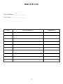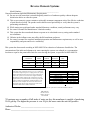
1
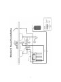
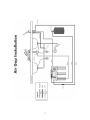
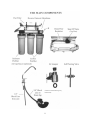
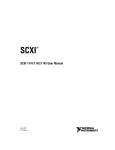
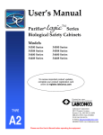
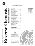
Black OWNER’S MANUAL OWNER’S MANUAL MODEL ___________ MODEL ___________ REVERSE OSMOSIS DRINKING WATER SYSTEMS REVERSE OSMOSIS DRINKING WATER SYSTEMS Authorized Dealer ________________________ Phone No. ______________________ Authorized Dealer ________________________ Phone No. ______________________ Contents CONGRATULATIONS! …………………………………….. 2 INTRODUCTION ……………………………………………. 3 GENERAL HINTS …………………………………………… 3 HOW YOUR REVERSE OSMOSIS SYSTEM WORKS …. 4 DIRECTIONS FOR CHANGING FILTERS ………………. 5 INSTALLATION INSTRUCTIONS ………………………... 6 STANDARD FAUCET INSTALLATION ………………….. 7 AIR GAP INSTALLATION …………………………………. 8 THE MAIN COMPONENTS ………………………………... 9 COMMON PROBLEM/SOLUTIONS …………………….. 10 SERVICE LOG ……………………………………………… 12 Congratulations! Your choice of the Reverse Osmosis System will yield purer, healthier, and better tasting water in your household. You have invested in a very sophisticated home drinking appliance. Please take the time to carefully review this manual. To realize your system’s maximum performance, you should become familiar with your system and how Reverse Osmosis works. Warning This Reverse Osmosis system should not be used where the water is microbiologically unsafe or with water of unknown quality without adequate disinfection before and/or after the filter. Your local dealer can assist you with testing of the source water and additional treatment if necessary. Installation by a trained professional is recommended. Your local dealer is familiar with the installation, operation and maintenance of your Reverse Osmosis system. Copyright© 1997 All Rights Reserved 2 INTRODUCTION Your Reverse Osmosis (R.O) System provides clear, fresh water in your home. This compact unit is designed to force pressurized water through a semi-permeable membrane which rejects contaminants suspended in the water. This membrane permits passage of the improved water to a holding tank. It is then available for use for drinking, cooking, or making ice cubes. GENERAL HINTS USE LOTS OF R.O. WATER: Your R.O. system will perform better and last longer with heavier usage. Use your R.O. water for pets, plants, steam irons, developing pictures, aquariums, automobile batteries, juices, infant formula, ice cubes, cooking, coffee and tea, etc. See what a difference it makes. TO KEEP WATER IT’S FRESHEST: In addition to heavy usage it is a good idea to drain your storage tank once a week. Before going to bed, open the faucet and let it run until it stops. Once it has stopped, close the faucet, your tank will refill during the night. WHILE GONE ON VACATION: If the water supply to your house is turned off, or if you are gone more than 1 month, you must remove the R.O. membrane to protect it from drying out. Remove entire membrane module housing, wrap in plastic and store in refrigerator until you return. You will also need to drain the storage tank to prevent bacteria growth. Discard the first tank water of water after restarting the system upon your return. If you will be gone for a short time and water supply is not turned off you should leave your faucet handle in the up position. This slow dripping will help prevent the build up of bacteria. CHANGE FILTERS AS RECOMMENDED: This cannot be over emphasized. After 6-12 months of collecting dirt, sand, and other impurities, these filters cannot hold any more. The filters may plug up completely cutting off the flow of drinking water or they may allow these impurities to pass through to the sensitive R.O. membrane causing damage and reducing the purity of your water. PROTECT AGAINST FREEZING: Failure to do so may result in cracking of the filter housing and water leakage. MAIL IN REGISTRATION CARD: Return to insure proper warranty coverage. KEEP RECORDS: Use the space provided on page 12 for service records. 3 HOW YOUR REVERSE OSMOSIS SYSTEM WORKS Your Reverse Osmosis System is completely self contained and uses stages for primary filtration and separations. FIRST STAGE: Prefilter The prefilter protects the reverse osmosis membrane from clogging by removing suspended and particulate matter larger than approximately 5 microns. The life of the prefilter depends upon the quality of the incoming tap water. Generally, we recommend replacing every six to twelve months. Please see the directions for changing filters on page 5. Model VI-TFC: Recommend replacing every 12 months 1-5 Micron sediment prefilter 1-Carbon prefilter 1-Carbon postfilter Model VII-TFC: Recommend replacing every 12 months 1-5 Micron sediment prefilter 2-Carbon prefilter 1-Carbon postfilter SECOND STAGE: Reverse Osmosis Membrane The R.O. membrane is the heart of the system. This is where most of the dissolved solids and remaining impurities are filtered and flushed out the drain. The life of the R.O. membrane depends greatly upon the quality of the incoming water source. Having a soft water supply will greatly increase its life expectancy. The membrane should be changed when it rejects less than 60% of dissolved minerals. Call your dealer for information on monitoring devices or water check programs. THIRD STAGE: Activated Carbon Postfilter The carbon postfilters function is to reduce tastes, odors, and chlorine, and is the final stage of filtration. It should be replaced every 12 months. See the directions for changing filters on page 5. 4 DIRECTIONS FOR CHANGING FILTERS HOW OFTEN YOU CHANGE YOUR FILTERS VARIES ON THE QUALITY OF WATER COMING TO THE RO AND THE AMOUNT OF WATER PRODUCED BY THE RO. THE RO FILTERS SHOULD BE CHANGED AT LEAST EVERY YEAR, BUT IF WATER QUALITY IS LOW OR HIGH AMOUNTS OF WATER ARE USED, IT IS RECOMMENDED THAT THEY BE CHANGED MORE OFTEN. FILTERS CANNOT BE CHANGED TOO OFTEN. PRE FILTERS: 1. Turn off cold water supply and valve on top of storage tank. Wait for pressure to bleed off. 2. Unscrew housing from cap, discard used cartridge and remove o-ring. Clean housing with hot water and 1 tablespoon of bleach. Rinse thoroughly. 3. Wipe o-ring clean and place back in groove. Make sure the o-ring is properly seated when installing. 4. Insert replacement cartridge (some filters have an arrow that points up, so they must be installed in the direction of the arrow). Screw housing onto cap and tighten. 5. Take off yellow line going to the membrane housing, open water supply valve and flush filters for 2-3 minutes or until water turns clear. Reconnect yellow line going to the membrane housing and turn on inlet and tank valve. CHECK FOR LEAKS. POST FILTERS: 1. Turn off cold water supply and the valve on top of storage tank. Wait for pressure to bleed off. 2. Remove fittings from post filter, discard post filter. Teflon tape old fittings and install on new filter. 3. Turn on inlet and tank valve, open faucet for 2 minutes to flush filter. CHECK FOR LEAKS. STORAGE TANKS SERVICE: It is important that the storage tank maintains the correct air pressure to operate correctly. If the air pressure is to low, the tank will only push a cup or two of water out. If the air pressure is too high the tank will never fill up with water. The correct pressure is 7 to 10 psi when the tank is EMPTY of water. 1. Shut off water inlet and open faucet to drain tank. (if the tank will not drain completely, pump air into tank to completely drain tank). 2. With tank empty check air pressure, add or release air until you reach between 7 to 10 psi. 3. Turn water back on and let tank fill up. 5 INSTALLATION INSTRUCTIONS See page 7 and 8 for illustration IMPORTANT: If water pressure exceeds 90 psi you must install a pressure regulator. IMPORTANT: Some RO’s use quick connect plastic fittings, to work properly the tubing must be smooth, cut straight and inserted completely into the fitting. If tubing is scarred, cut at an angle or not inserted all the way there is a higher possibility of leaks. STEP #1: Select a convenient location for faucet. Make sure the bottom of faucet is accessible for making the line connection and securing faucet to sink. STEP #2: Drill hole for faucet, regular faucet requires ½” hole, air gap faucets require 1” holes (Optional faucets might require different size holes). STEP #3: With water turned off install EZ adapter between angle stop and sink, make sure that ball valve with 1/8” MPT is installed on easy adapter. STEP #4: Select location for drain saddle, the best location is the horizontal section of drain pipe. If there is none, locate the drain saddle just above the water line in drain trap to prevent dripping sound. Drill ¼” hole and position drain saddle hole and gasket over the hole drilled in pipe. Note: If the hole in the pipe and the hole in the drain saddle are not lined up, the RO will not function properly. STEP #5: Mount the RO where it can be serviced properly and easily. STEP #6: Connect ball valve to tank using Teflon tape. (If not already connected) STEP #7: Connect the yellow line to the EZ adapter ball valve. Connect red line to storage tank. Connect black line to drain saddle (For non air gap installation). Connect ¼” black line to small barb on bottom of faucet (For air gap installation). Connect the 3/8” black line to large barb on faucet and connect other side to drain saddle (Make sure that there are no kinks or excessive amount of 3/8” tubing, because this tubing is only gravity feed) STEP #8: Disconnect yellow tubing from feed side of membrane housing. Turn on supply valve and run water till it runs clear. Now shut off water supply and connect yellow tubing back to membrane housing. See page 9 * START UP: Open inlet valve, wait for unit to pressurize and check for leaks. Let unit fill up tank (approx 4-6 hours) then dump 1st tank of water to flush out post filter. (Only if tank is not pre filled) 6 7 8 (must be cut to allow direct gravity feed to drain) 9 COMMON PROBLEMS/SOLUTIONS “I have too much Total Dissolved Solids (TDS) in the product water” 1. Membrane expanded. Replace membrane module. (Contact your local dealer) 2. Membrane attacked by chlorine. (does not apply to CTA element) Carbon prefilter may be exhausted. Replace with new cartridge. 3. Check valve failure on low control assembly. Replace check valve tee. (Contact your local dealer) 4. Insufficient brine flow rate/screen on flow control assembly plugged. Replace or flush out screen and/or flow control assembly. (Contact your local dealer) 5. Clogged prefilter/creates pressure drop and low brine flow. Replace prefilter cartridge. 4. Feed pressure too low. Feed pressure must be at least 40 psi. 7. Insufficiently flushed postfilter cartridge. Flush postfilter with RO water. One or two tanks should be sufficient. 8. Increase in feed water TDS. (Contact your local dealer) “I have no water or not enough water” 1. Feed water shut off. Turn on feed water. 2. Low feed pressure. Feed pressure must be at least 40 psi. 3. Prefilter cartridge clogged. Replace prefilter cartridge. 4. Screen or flow control assembly plugged. Replace or flush out screen and/or flow control assembly. (Contact your local dealer) 5. Membrane fouled. Determine and correct cause or replace membrane. (Contact your local dealer) 10 “My R.O. is constantly running.” 1. Check tank pressure and check valve. Tank pressure should be 10 psi empty. “I’ve noticed poor taste/odors in the product water.” 1. Increase in product TDS. Flush tank completely. See “I have too much Total Dissolved Solids (TDS) in the product water.” 2. Postfilter expended. Replace postfilter cartridge. 3. Tank/system contaminated. Replace prefilter and postfilter and sterilize tank and system. 4. Tank diaphragm out of place. Replace tank and postfilter cartridge. 5. Postfilter cartridge not completely flushed Flush two tanks of RO water through system. “The product water is cloudy.” Let the water stand until dissolved water dissipates. It usually clears up as the condition of the feed water changes. Call your local dealer for continued problems. 1. Dissolved air from feed water that has concentrated in the product water. “My ice cubes are cloudy.” 1. Increase in product water Total Dissolved Solids. Flush tank and see “I have too much Total Dissolved Solids (TDS) in the product water.” 2. Some shapes of ice cubes can trap more dissolved air. Large square cubes are generally clearer than small round cubes. Try using a different ice cube mold. Try switching ice cube maker from automatic to manual. Let the water stand until dissolved water dissipates, then allow to freeze. See “The product water is cloudy.” 11 SERVICE LOG Date of Installation _____________________ Serial Number _________________________ DATE TYPE OF SERVICE 12 COMMENTS 4 & 5 STAGE RO 13 Reverse Osmosis Systems Model Number:__________________________________________ General Installation/Operation/Maintenance Requirements Do not use with water that is microbiologically unsafe or of unknown quality without adequate disinfection before or after the system. This reverse osmosis system contains a replaceable treatment component critical for effective reduction of total dissolved solids. The product water shall be tested periodically to verify that the system is performing satisfactorily. While testing was performed under standard laboratory conditions, actual performance may vary. See owner’s manual for Manufacturer’s limited warranty. This system has been tested and shown to operate at its calculated recovery rating under standard test conditions. Chlorine in the influent water may affect the RO membrane polymers. See owner’s manual for complete installation/operation and maintenance requirements, as well as user responsibility and parts and service availability. This system has been tested according to NSF/ANSI 58 for reduction of substances listed below. The concentration of the indicated substances in water entering the system was reduced to a concentration less than or equal to the permissible limit for water leaving the system, as specified in NSF/ANSI 58. Contaminant Ave. Influent Ave. Effluent Ave. % Reduction USEPA MCL Pentavalent Arsenic 290.30 vg/L 6.74 vg/L 98 10 vg/L Lead 143.6 vg/L 1.91 vg/L 99 10 vg/L TDS 777.1 ppm 20.24 ppm 98 187 ppm This system has been tested for the treatment of water containing Pentavalent arsenic (also known as As(V), As(+5), or arsenate) at Concentrations of [0.050 mg/L or 0.30 mg/L] or less. This system Reduces pentavalent arsenic, but may not remove other forms of arsenic. This system is to be used on water supplies containing detectable free chlorine residual at the system inlet or on water supplies that have been demonstrated to contain only pentavalent arsenic. Treatment with chloramines (combined chlorine) is not sufficient to ensure complete conversion of trivalent arsenic to pentavalent arsenic. Please see the Arsenic Facts section of the Performance Data Sheet for further information. Electrical Requirements Daily Production Rate Efficiency rate* System Weight System Dimensions Max./min. pressure Max./min. temperature If applicable 7.5 8.1% 25 lbs 7 x 17 x 15 40-80 psi 40º F- 110º F Test parameters: 25º + 1ºC, 50 psi, and pH of 7.5 *Efficiency rating means the percentage of the total water required to operate the system that is treated and available to the user. B&R Industries 1456 W. Scott Ave. Gilbert, AZ 85233 480-898-0008 *If customer uses a number of full tanks of water per day, this membrane is capable of producing 20-24 gal/day. The higher the pressure is over 50 psi, the more water the unit will produce. Authorized Dealer ________________________________ Phone __________________________________________