1
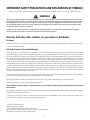
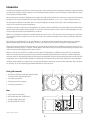
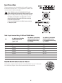
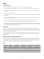
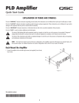
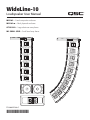
WideLine-10
Loudspeaker User Manual
WL2102 – Cored composite enclosure
WL2102-w – Birch plywood enclosure
AF2102-LA – Large aluminum array frame
WL Small Grid – Small steel array frame
TD-000227-00-C
*TD-000227-00*
IMPORTANT SAFETY PRECAUTIONS AND EXPLANATION OF SYMBOLS
Install in accordance with instructions by QSC Audio Products, LLC instructions and under the supervision of a licensed Professional Engineer.
WARNING!
Before placing, installing, rigging, or suspending any speaker product, inspect all hardware, suspension, cabinets, transducers, brackets and
associated equipment for damage. Any missing, corroded, deformed, or non-load rated component could significantly reduce the strength of
the installation, placement or array. Any such condition severely reduces the safety of the installation and should be immediately corrected.
Use only hardware which is rated for the loading conditions of the installation and any possible short-term, unexpected overloading. Never
exceed the rating of the hardware or equipment.
Consult a licensed, Professional Engineer regarding physical equipment installation. Ensure that all local, state and national regulations
regarding the safety and operation of suspension equipment are understood and adhered to.
Warranty (USA only; other countries, see your dealer or distributor)
Disclaimer
QSC Audio Products, LLC is not liable for any damage to amplifiers or any other equipment that is caused by negligence or improper installation and/
or use of this loudspeaker product.
QSC Audio Products 3-Year Limited Warranty
QSC Audio Products, LLC (”QSC”) guarantees its products to be free from defective material and/or workmanship and will replace defective parts and
repair malfunctioning products under this warranty when the defect occurs under normal installation and use-provided the unit is returned to our factory,
one of our authorized service stations or an authorized QSC International Distributor via pre-paid transportation with a copy of proof of purchase (i.e.,
sales receipt). This warranty provides that the examination of the return product must indicate, in our judgment, a manufacturing defect. This warranty
does not extend to any product which has been subjected to misuse, neglect, accident, improper installation, or where the date code has been removed
or defaced. QSC shall not be liable for incidental and/or consequential damages. This warranty gives you specific legal rights. This limited warranty is
freely transferable during the term of the warranty period. The warranty on QSC products is NOT VALID if the products have been purchased from an
unauthorized dealer/online e-tailer, or if the original factory serial number has been removed, defaced, or replaced in any way. Damage to, or loss of any
software or data residing on the product is not covered. When providing repair or replacement service, QSC will use reasonable efforts to reinstall the
product’s original software configuration and subsequent update releases, but will not provide any recovery or transfer of software or data contained on
the serviced unit not originally included in the product.
Customers may have additional rights, which vary from state to state or from country to country. In the event that a provision of this limited warranty is
void, prohibited or superseded by local laws, the remaining provisions shall remain in effect.
Periodically, this warranty is updated. To obtain the most recent version of QSC’s warranty statement, please visit www.qscaudio.com.
Contact us at 800-854-4079 or visit our website at www.qscaudio.com.
The QSC limited warranty is valid for a period of three (3) years from date of purchase in the United States and many (but not all)
other countries.
For QSC warranty information in countries other than the United States, contact your authorized QSC international distributor. A list of QSC International
distributors is available at www.qscaudio.com.
To register your QSC product online, go to www.qscaudio.com and select ”Product Registration”. Other questions regarding this warranty can be
answered by calling, e-mailing or contacting your authorized QSC distributor.
© 2009, QSC Audio Products, LLC.
Patents may apply or be pending.
QSC is a registered trademark of QSC Audio Products, LLC.
“QSC” and the QSC logo are registered with the U.S. Patent and Trademark Office.
All trademarks are the property of their respective owners.
1
Introduction
The WideLine-10 loudspeaker system has been designed to provide a compact system that has unique dispersion characteristics, high-power handling
and extended low-frequency response. Its primary uses include ballrooms, theatres, night clubs, houses of worship, and small to medium size events
for the corporate and industrial markets.
WL2102 enclosures are constructed of lightweight cored-composite and weigh 70 lb (31.8 kg). WL2102-w enclosures are constructed of birch plywood
and weigh 83 lb (37.7 kg). The hardware allows for simple vertical splay angle adjustment of 0, 2, 3, 4, 5, 6, 7, 8, 9, and 10° between enclosures.
Two array frames are available. The WL Small Grid is for suspended applications or stacking on top of QSC’s 215SB or 215PCM subwoofers. The
AF2102-LA is for suspended or ground stack applications.
The WideLine-10 system is suitable for stand alone applications as a full-range, articulate, high-fidelity, sound reinforcement product with the ability to
reproduce many musical programs without subwoofers or bass modules. It has bass response to 55 Hz (-3 dB) in a small format package. Its 3-way,
bi-amp or tri-amp design keeps required amplification to a minimum.
WideLine-10’s exceptionally wide dispersion practically eliminates the need for “side” or “fill” hangs when used as the main array. Its wide dispersion also provides enhanced coverage when used as a center cluster or as a downfill or underhang enclosure when used with larger format line
array systems.
Wide dispersion is accomplished with a 3" (76 mm) diaphragm, 1.4" (36 mm) exit neodymium high-frequency driver mounted on a proprietary,
patented* multiple aperture diffraction-slot waveguide. This device is the ideal linear source needed for wide angle line array performance.
Internal, mid-frequency shading can be switched to either 10" (254 mm) transducer. Both transducers handle the low frequencies, but only the nonshaded transducer handles the mids. This provides smoother pattern control at the mid-high crossover. With selectable shading, the enclosures can be
used as house right or left by flipping the switch, not the enclosure.
WideLine-10 users can also use EASE Focus software to aid in the design and implementation of a WideLine-10 array. EASE Focus can calculate the
number of enclosures required for a given space (venue), determine the optimum splay angle between those enclosures, calculate at what angle to
set the array frame in a single (variable) pick-point or fixed suspension point application, and predict the acoustical response and sound pressure levels
throughout the venue in a two-dimensional illustration. The software may be downloaded from the QSC website. Contact QSC for more information.
Like all QSC products, WideLine-10 design focuses on accurate audio performance, rapid set-up, and reduced labor requirements. Ease of transportation, assembly, use, and self contained rigging hardware make WideLine-10 the clear choice.
Front (grille removed)
1
3
2
1
4
1. Receiver tube (front left and right) with captive articulated
joint (inside receiver tube) and ball-lock pins
2. Low-frequency transducer B
3. High-frequency transducer aperture
4. Low-frequency transducer A
Rear
6
5. Input / output connectors (NL8)
5
6. Rear link, mounting block, and ball-lock pin
7. TRI AMP / BI AMP selector switch
8. MF (UNSHADED) SELECT switch
*Patent number 7,177,437
2
7
8
TRI AMP/BI AMP Switch
TRI AMP
TRI AMP: Shading network is NOT applied (shading must be provided
by upstream signal processing). Connect the full-range input signal to
pins 1+ and 1-, connect the shaded (processed) signal to pins 2+ and
2-. To flip shaded transducer location, use the MF (UNSHADED) SELECT
switch or alter signal processing. Default MF (UNSHADED) SELECT
switch position for three way mode is position A; if put in position B,
connections (Table 1) to LF transducers A and B are interchanged.
BI AMP: The “full-range” LF input is applied to pins 1+ and 1- and the
-6 dB per octave shading network is applied to one of the LF transducers
using the MF (UNSHADED) SELECT switch.
BI AMP
MF (UNSHADED) SELECT Switch
A
The WideLine-10 is a 3-way design (shaded, non-shaded and highfrequency) with shading provided by a passive network in BI AMP mode
or upstream signal processing (DSP) in TRI AMP mode. This allows switch
position selection for use as either “house left” or “house right”, without
the need to invert boxes.
BI AMP: The shading switch allows either low-frequency transducer
to be selected as the shaded unit (bass only) by inserting a -6 dB per
octave network. The switch handle points to the side of the unshaded
(full-range) low-frequency transducer.
B
MF (UNSHADED)
SELECT
MF (UNSHADED) SELECT Switch: BI AMP Mode
Pins 1+, 1-6dB per octave
LF Transducer A
LF Transducer B
Pins 2+, 2- : not used
Pins 3+, 3- : not used
Pins 4+, 4-
TRI AMP: The internal -6 dB per octave network is NOT applied to
either LF transducer. Shading is accomplished with signal processing.
The switch handle points to the side of the non-shaded (full-range)
low-frequency transducer ONLY IF the full-range signal is applied to
pins 1+ and 1- and the shaded signal to pins 2+ and 2-. Default position
for TRI AMP mode is position A; if put in position B, connections to LF
transducers A and B are interchanged.
HF Transducer
MF (UNSHADED) SELECT Switch: TRI AMP Mode
Pins 1+, 1-
LF Transducer A
Pins 2+, 2LF Transducer B
Pins 3+, 3- : not used
Pins 4+, 4-
3
HF Transducer
Input Connections
The input connectors are a pair of Neutrik NL8’s wired in parallel. Connections
for bi-amp and tri-amp vary (Table 1). The pin designations for the NL8FC cable
connector is shown for reference, bottom right.
Note! In TRI AMP mode, the MF (UNSHADED) SELECT switch
position determines the input connector wiring! Unexpected results
may occur if switch positions and wiring are not strictly controlled.
The WideLine-10 loudspeaker is not equipped with a crossover
network. All signal processing must be done before connecting
audio power to the loudspeaker.
Do not connect full-range audio to the high-frequency transducer
or damage may result!
Table 1: Input Connector Wiring, BI AMP and TRI AMP Modes
BI AMP Internal Shading
Network Inserted in
Signal Path
TRI AMP MF (UNSHADED)
SELECT Switch Position A
Use External Processing
for Shading,
TRI AMP MF (UNSHADED)
SELECT Switch Position
B Use External Processing
for Shading,
1+
LF +
LF A +
LF B +
1-
LF -
LF A -
LF B -
2+
Not Used
LF B +
LF A +
2-
Not Used
LF B -
LF A -
3+
Not Used
Not Used
Not Used
3-
Not Used
Not Used
Not Used
4+
HF +
HF +
HF +
4-
HF -
HF -
HF -
PIN
Neutrik NL8FC Cable Connector Pinout
Shown, at right, is a diagram of the pin designation inside the Neutrik NL8FC connector. This information
is for reference only. Diagram is of the connector as viewed from the wire-insertion end.
4
Rigging
Rules for Suspension
• Correct use of all suspension hardware and components is imperative in sound system rigging and deployment.
• Always calculate suspended loads before lifting to ensure suspension components and hardware are used within their respective load limits.
• Research local codes and regulations to fully understand the requirements for suspended loads in the venue in which the equipment is to
be suspended.
• Use only shackle holes for suspension of array.
• Be absolutely certain of the integrity of any structural member intended to support suspended loads. Hidden structural members can have hidden
structural weakness.
• Consult a professional mechanical or structural engineer licensed in the jurisdiction of the sound system installation to review, verify, and approve
all attachments to the building or structure.
• Never assume anything—owner or third-party supplied suspension attachment points may not be adequate for the loads to be suspended.
• Employ the services of a professional rigger for hoisting, positioning, and attaching the equipment to the supporting structure.
• Always inspect all components (enclosures, suspension brackets, pins, frames, bolts, nuts, slings, shackles, etc.) for cracks, wear, deformation,
corrosion, missing, loose, or damaged parts that could reduce the strength of the assembly before lifting. Discard any worn, defective, or suspect
parts and replace them with new appropriately load-rated parts.
Shock Loading
When a load is either moved or stopped, its static weight is magnified. Sudden movements can magnify the static weight several times. This
magnification of static weight is termed “shock loading”. Shock loading poses a danger to equipment and workers. The effects of shock loading can
be instantaneous, or they may remain undetected unless the equipment is visually damaged. Avoiding shock loading requires careful planning and
knowledge of equipment, rigging, and lifting practices.
Shock loading of equipment and structures is usually confined to lifting and installation, but natural forces (winds, earthquakes) can impose shock
loads several times the static load. This is why structures and suspension equipment must be capable of supporting several times the weight of the
equipment suspended.
WideLine-10 Working Load Limits and Design Factors
The following chart (Table 2) provides Working Load Limit data at various Design Factors. The tabulated Design Factors are for static loads only. The
choice of which Design Factor to use will depend upon the jurisdiction and venue of installation, as well as the conditions of suspension. Dynamic
conditions are determined by unknown, installation-specific factors and should be referred to a Licensed Structural Engineer for clarification before
proceeding with any suspension of the equipment. The data presented is based upon the listed component weights:
Table 2
Component
Weight
4:1 Design Factor
5:1 Design Factor
7:1 Design Factor
10:1 Design Factor
WL2102
70 lb / 31.8 kg
2300 lb / 1040 kg
1800 lb / 836 kg
1300 lb / 597 kg
920 lb / 418 kg
WL2102-w
83 lb / 37.7 kg
2500 lb / 1130 kg
2000 lb / 909 kg
1400 lb / 649 kg
1000 lb / 455 kg
AF2102-LA
37 lb / 16.8 kg
–
–
1423 lb / 646.8 kg
996 lb / 452.7 kg
WL SMALL GRID
33 lb / 15.0kg
1800 lb / 794 kg
1400 lb / 636 kg
1000 lb / 455 kg
700 lb / 318 kg
5
Rigging
1
WideLine-10 enclosures use a three-point suspension system. The system
consists of front, left/right, captive articulated joints and a single rear link
bar. Articulation is in 2° increments using the first location on the link
bar. With the use of the second location, 1° degree increments can be
obtained starting at 3°. The total available angular increments are: 0, 2,
3, 4, 5, 6, 7, 8, 9, and 10°. All pieces and locking pins remain with the
enclosures. No ancillary items are needed to suspend the enclosures from
the WideLine-10 array frame. All ball-lock pins are equipped with a lanyard
to help prevent loss.
2
1. Front Articulated Joint—Slide
the joint out of the receiver
tube by sliding the retaining
screw upward.
2. Then lock in place using the
ball-lock pin.
Front Articulated Joint (Knuckle) Hardware
Expose the end of the articulated joint by locating the joint’s retaining
screw protruding from the front of the receiver tube and sliding it upward.
The front captive joint will slide upward from the enclosure’s receiver tube.
The exposed end of the articulated joint can now be inserted into the
adjacent enclosure’s receiver tube and locked into position by a locking
pin. This is repeated for each side of the enclosure. Then the rear link bar
can be rotated into position and pinned at the chosen increment.
Rear Link (Angle Adjust) Hardware
The rear link is stored with the link folded between the sides of the block.
To expose the link, remove the ball-lock pin and rotate the link into the
desired position. Once positioned, the link is secured using the ball-lock
pin of the adjacent enclosure.
The rear link is marked with a thin, white line at the “normal” (0°) position
and with a “+3” at the +3° position.
1. Rear Link—Remove the
ball-lock pin from the
storage position, then
rotate the link downward to the adjacent
enclosure.
1
2. Lock in place using the
ball-lock pin.
The additional ball-lock pin hole (located approximately midway on the
link) is used for storing the link when folded into the enclosure’s block for
storage. The link may be pinned in place at the 0° or 8° location on the
block when rotated into the storage position.
2
6
Adjusting the Angle Between Enclosures (Splay)
The illustration shows the rear pin block of two enclosures joined by the
upper enclosure’s rear link arm.
Use the first pin location (closest to the end) on the link arm for setting in
normalized 2° increments. The left-side example shows two enclosures
linked for 8° of splay. The ball-lock pin is inserted into the 8° position in
the rear block while passing through the “normal” pin hole in the link.
When the “+3“ location is used, an additional 3° are added to the
“normalized” location. The right side example shows two enclosures
linked for 9° of splay. The ball-lock pin is inserted into the 6° position in
the rear block while passing through the “+3°” pin hole in the link. The
total splay is the 6° indicated on the block, plus the 3° additional from
the link position, for a total of 9°. In this manner 1° increments can be
attained starting with 3° (0° block location and +3° link arm location).
Rear link attached to
achieve an 8° splay
between enclosures.
Rear link attached
to achieve a 9° splay
between enclosures.
AF2102-LA and WL Small Grid
There are two array frames available for the WideLine-10 system.
The AF2102-LA is used for suspending larger arrays. The AF2102-LA may
be inverted and used for ground stacking.
The WL Small Grid is a compact and easier to handle frame for use
as a small array or stacking frame. This frame will easily sit on ground
stacked bass enclosures or it can be used to suspend smaller arrays
from the stage trusses.
AF2102-LA
Use only the QSC supplied 5/16" diameter x 1.25" long
ball-lock pins or equivalents from a reputable source on front
receiver tubes.
31.6"
(803 mm)
The three pick up rails allow for any number of rigging solutions to fit
the most demanding venues. The rails are drilled for industry standard
5/8" shackles.
Do not stack more than eight (8) enclosures on the
AF2102-LA Frame.
Bolt on receiver
tube and 5/16"
diameter, 1.25"
long ball-lock pin.
14.8"
(376 mm)
37.0"
(940 mm)
Left pickup rail
Center pickup rail
Right pickup rail
Front
7
AF2102-LA
The link arm is located on the bottom side of the frame assembly. Use this link for attaching the rear of the first enclosure. The frame allows for up or
down angle options for use with either stacking or suspending. The 4° “normal” locations on the link system will yield a net 0° vertical inclination.
Use 4° link location for 0°
vertical inclination.
WL Small Grid
Do not stack more than four (4) enclosures on a WL Small GRID.
Use only the QSC supplied 5/16" diameter x 1.25" long ball-lock pins or equivalents from a reputable source on front receiver tubes.
The WL Small Grid interfaces with QSC’s 215PCM or 215SB subwoofer in either a stacked or flown configuration. The stacking bumpers on the
frame may need to be moved to the opposite side of the frame member for use. The small frame is constructed using standard “L” track for rigging.
25.7"
(653 mm)
5/16" diameter, 1.25" long
ball-lock pins.
Stacking bumpers align
with stand sockets of QSC
215PCM subwoofer window.
19.5"
(696 mm)
Standard L-track
Bumpers
8
Stacking the WL Small Grid
The WL Small Grid comes with two aluminum I-bars used for aligning and securing the frame to QSC’s 215SB or 215PCM subwoofer.
To use the I-bars, simply slide each one into the small frame’s L-track and secure with a stud fitting. Then, turn the frame over (I-bars on the bottom)
and slide the exposed I-bars into the subwoofer’s L-track. Secure the I-bar with a stud fitting. Note that the stud fittings used are not required to be
load rated as they only retain the I-bars from moving laterally.
When stacking a WL Small Grid on top of QSC’s 215SB or
PCM cabinet, use the I-beam inserts (1 in each L-track) to
assure proper alignment and to firmly secure the frame to the
215 cabinet. Secure using stud fittings.
I-beam stacking bar: slide into
L-track on WL Small Grid, then
align and slide into L-track on
subwoofer window.
Do not stack more than four (4) enclosures on a WL
Small Grid.
Care
We suggest wiping down all screws, pins, hardware, and frames with LPS®
Dry Film Lube or Starrett M1® All Purpose Lube before and after outside
gigs to help prevent oxidation. This will not only prevent the formation of
rust and other oxides, but also provide lubrication, adding to the longevity
and ease-of-use of the WideLine-10 product.
Dimensions
25.0"
(635 mm)
20.75"
(527 mm)
10.75"
(273 mm)
7.7"
(196 mm)
Side
10.1"
(257 mm)
20.4"
(518 mm)
27.5"
(699 mm)
Top
26.8"
(681 mm)
Front
Rear
NOTE! Composite enclosures have approximately 1° of draft on the enclosure sides; the birch plywood enclosures do not. Handle
orientation may vary between composite and plywood enclosures.
9
Specifications
WL2102
WL2102-w
Configuration
Bi-amp or tri-amp mode
Transducers
Low-frequency
High-frequency
2 x 400 W, 16Ω 10" woofer, 3" voice coil, ceramic magnet assembly
1.4" exit, 3" titanium diaphragm, neodymium magnet assembly
Frequency Response (±3 dB)1
55 Hz – 18 kHz (with recommended DSP processing)
Frequency Range (-10 dB)
48 Hz – 20 kHz (with recommended DSP processing)
Nominal Impedance
HF: 16Ω
LF bi-amp mode: 8Ω
LF tri-amp mode: 16Ω (x 2)
Continuous Power Capacity /
Recommended Power
HF: 80 W / 300 W (2 hours, AES1984-2 method, 1 – 10 kHz)
LF bi-amp mode: 600 W / 1400 W (2 hours, AES1984-2 method, 80 – 800 Hz)
LF tri-amp mode: 400 W / 700 W (x 2) (2 hours, AES1984-2 method, 80 – 800 Hz)
Sensitivity (1 W at 1 m)
HF: 107.5 dB (single cabinet measured in free space)
LF: 98 dB (single cabinet measured in free space. LF drivers connected in parallel)
Maximum Output
Continuous / Peak (SPL at 1 m)
HF: 127 dB / 133 dB
LF: 127 dB / 133 dB
Nominal Coverage
H: 140°
V: dependent on number of elements used
Cabinet Type
Ported / trapezoidal
Enclosure Material
Cored composite
Finish
Black or white texture coat
Grille
Perforated, formed powder coated steel
Connectors
2 x Neutrik Speakon® NL8 in parallel
Pin Outs
Pins
1+/1-
2+/2- 3+/3- 4+/4- Attachment Points
Integral, adjustable rigging system, vertical splay adjustable in 1° increments from 0° – 10°
Weight (Net / Shipping)
70 lb (31.8 kg) / 78 lb (35.5 kg)
Dimensions (HWD)
10.8" x 27.4" x 20.75" (274 mm x 696 mm x 527 mm)
Available Accessories
WL Small Grid
AF2102-LA
For suspended or stacking applications on QSC’s 215SB or 215 PCM subwoofer.
Frame used for suspending or stacking applications. Frame weight 37 lb/16.8 kg.
Software
Ball-lock Pins
WL2102
Bi-Amp
LF NC NC HF Baltic birch plywood
Tri-Amp
MF
LF
NC
HF
83 lb (37.7 kg) / 91 lb (41.4 kg)
EASE Focus line array modeling software tool available; visit www.qscaudio.com or contact QSC’s Technical Services for
DSP files for both QSControl.net and Signal Manager
Nylon Lanyard 5/16" D x 0.75" H, t-handle: p-n SR-000052-00 (Rear link and Front tube pin)
WL2102-w
7" Stainless steel lanyard 5/16" D x 0.75" W, t-handle: p-n HW-000106-00 (Rear link pin)
5" Stainless steel lanyard 5/16" D x 0.75" W, t-handle: p-n HW-000126-00 (Front link pin)
AF2102-LA
4" Stainless steel lanyard 5/16" D x 1.25" W, Round head HW-000162-00 (Rear link pin)
WL Small Grid
9" Stainless steel lanyard 5/16" D x 1.25" W, Round head. HW-000163-00 (Rear link pin)
1) With recommended DSP settings
Specifications subject to change without notice.
10
Mailing Address:
QSC Audio Products, LLC
1675 MacArthur Boulevard
Costa Mesa, CA 92626-1468 USA
Telephone Numbers:
Main Number: (714) 754-6175
Sales & Marketing: (714) 957-7100 or toll free (USA only) (800) 854-4079
Customer Service: (714) 957-7150 or toll free (USA only) (800) 772-2834
Facsimile Numbers:
Sales & Marketing FAX: (714) 754-6174
Customer Service FAX: (714) 754-6173
World Wide Web:
www.qscaudio.com
E-mail:
[email protected]
[email protected]
© 2009 QSC Audio Products, LLC. All rights reserved. QSC, the QSC logo and WideLine are registered trademarks of QSC Audio Products, LLC in the U.S. Patent and Trademark office and other countries.
Speakon and Neutrik are trademarks of Neutrik. All other trademarks are the property of their respective owners. US Pat. 7,177,437. Other patents may apply or be pending.