1
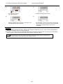
MITSUBISHI
Mitsubishi Limiservo X
G series
TECHNICAL INSTRUCTION MANUAL
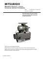
Motor
XL-G554-10(Y), XL-G554-20(Y)
Control box
XC-GMFY
Induction type AC servo motor
and control box with automatic
needle positioner
Thank you for purchasing this product.
Please read this manual thoroughly before use to ensure safe and proper use.
Please read the instruction manual for the machine head together with this manual.
Save this manual for future reference.
E723D877-*(200603)
1
1
2
3
4
5
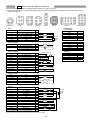
Contents
Contents ······························································································································································· 1
Safety Instructions················································································································································ 2
Points of Caution ·················································································································································· 3
Names of Each Part ············································································································································· 4
Installation ···························································································································································· 5
1. Installation of the motor ·················································································································································5
2. Installation of the control box·········································································································································5
3. Installation of the pulley ·················································································································································5
4. Mounting of the belt ·······················································································································································5
5. Installation of the protective cover ·································································································································6
6. Installation of the position detector ································································································································7
7. Connection of the Mitsubishi sewing machine and control box·····················································································7
6
Wire and Grounding ············································································································································· 8
1. Insertion of the power connector ···································································································································8
2. Connection of 3-phase power ·······································································································································8
3. Current capacity ····························································································································································8
4. When using the 3-phase 200 - 240V class Limiservo X with single phase 200 - 240V class ·······································8
7
Confirmation ························································································································································· 9
1. Before turning switches on.......... ··································································································································9
2. Turn on the power..........················································································································································9
8
Adjustments························································································································································· 10
1. Adjustment of stopping position····································································································································10
2. Adjustment of pedal toe down pressure, and heeling pressure····················································································10
3. Adjustment of operation speed ····································································································································· 11
9
Changing the solenoid voltage and output voltage······························································································ 12
1. To change solenoid voltage DC24V/DC30V·················································································································12
2. Changing the output voltage between 0VDC and 5VDC······························································································12
10
Operation of the Control switch Panel Keys ······································································································ 13
1. Displays during normal mode and functions of each key ·····························································································13
2. Selection of each mode ················································································································································13
(1) Types of program mode ····································································································································13
(2) Selection of each program mode from the normal mode. ·················································································14
(3) Direct number call function································································································································15
3. Using the normal mode ················································································································································16
4. Changing to the tacking, preset, pattern NO. selection mode ······················································································17
(1) Tacking setting mode ········································································································································17
(2) No. of tacking stitches setting mode ·················································································································17
(3) Preset stitching setting mode ····························································································································18
(4) Pattern No. selection mode·······························································································································18
5. Using the program mode [1] simple setting··················································································································19
6. Using the program mode [2] simple setting··················································································································21
7. Using the program mode [3] simple setting··················································································································23
11
Example of setting the program mode ··············································································································· 25
1. To change the maximum speed····································································································································25
2. To set the standing work type ·······································································································································25
3. To operate Half-stitch operation with a backstitching switch ························································································26
4. Outputting puller output to spare output 02 ··················································································································26
5. Setting the number of stitches to the UP position stop after fabric end is detected with optical sensor, etc. ···············27
6. To continue presser foot lifting after the thread trimming, and to bring down the presser foot after the time
set on the timer has passed··········································································································································28
7. When after trimming thread while sewing thick fabric, needle is stuck and fabric cannot be removed························28
8. To display the rotation speed on the operation panel ···································································································29
9. To adjust the tacking accurately ···································································································································30
10. Setting the tacking stitch correction····························································································································31
11. Example of setting counter function····························································································································32
12. To check the error code history and input/output signal ·····························································································33
13. To return all settings to the factory settings ················································································································35
14. To adjust the position data for the lever unit ···············································································································36
12
13
14
To save the setting data····································································································································· 37
Function List ······················································································································································ 38
How to Use the Option Connector····················································································································· 42
1. Connector Layout ·························································································································································42
2. To use as a standing work type sewing machine ·········································································································43
15
16
Error Display······················································································································································ 44
Specifications ···················································································································································· 45
<Reference> Table of digital display··················································································································· 45
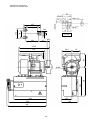
Dimensions (MOTOR and CONTROL BOX)······················································································· 46
-1-
2
Safety Instructions
1. To ensure safe use
*Always observe the following items to ensure safe use of the industrial sewing machine drive unit (motor and control box).
1.1 Before starting
Read all instruction manuals thoroughly before starting use of this drive unit, and follow the technical manuals. Also read the instruction
manuals for the installed sewing machine.
1.2 Application and purpose
This drive unit is designed to drive a sewing machine and must not be used for other applications or purposes. Do not use this drive unit until
it can be confirmed that safety measures for the installed sewing machine have been taken.
1.3 Work environment
Use this drive unit in dry and well-kept clean locations, e.g. in the clothing industry, and which process dry sewing material.
Avoid using this control unit in the following types of environments.
(1) Power voltage
- Place where voltage fluctuation exceeds ±10% of the rated voltage.
- Place where the specified power capacity cannot be secured. (Refer to page 8)
(2) Electromagnetic
- Place where strong electric or magnetic fields are generated such as near a large-output high frequency
noise
oscillator or high frequency welding machine.
- Place where atmospheric temperature is 35 degree or higher and 5 degree or lower.
(3) Temperature
and humidity
- Place subject to direct sunlight or outdoors.
- Near a heat source such as a heater.
- Place where relative humidity is 45% or less and 85% or more, or where dew condensation occurs.
(4) Atmosphere
- Atmosphere with dust or corrosive gases.
- Atmosphere with combustible gases or explosive atmosphere.
(5) Altitude
- Place where altitudes exceeds 1,000m above mean sea level.
(6) Storage
- Place where storage temperature is 55 ℃ or higher and -25℃ or lower.
(7) Vibration
- If excessive vibration occurs when the control box is installed on the sewing machine, install it separately.
2. Installation
2.1 Motor and control box
- Correctly install according to the attached technical manuals.
2.2 Accessories
- Always disconnect this control unit from the main power supply when installing any accessories listed in the technical manual. (Turn the
main switch OFF, and remove the plug from the outlet (power supply line).)
2.3 Cable
(1) Arrange the connection cable so that excessive force is not applied during use, and do not excessively bend the cable.
(2) Cables near moving parts (e.g., pulley) must be wired at a minimum distance of 25mm.
(3) Confirm that the power voltage of the power cable for supplying to the control box meets the specifications on the motor and control box
rating nameplates before connecting it to the power line. Connect it to the designated places to supply the power. Perform this step with the
power switch turned OFF.
2.4 Grounding
- Correctly connect the power cable grounding to the power supply grounding.
2.5 Accompanying appliances and accessories
- Electric accompanying appliances and accessories must be connected to the place listed in this manual.
2.6 Removal
(1) Turn the power switch OFF and remove the plug from the outlet (power supply line) before removing the motor or control box.
(2) Do not pull on the cord when removing the plug. Always hold the plug itself.
(3) There is a high voltage applied inside the control box, so always wait at least 10 minutes after running the power switch OFF and
remove the plug from the outlet (power supply line) before opening the control box panel.
3. Maintenance, inspection and repairs
- Follow the technical manuals for maintenance and inspection of this control unit.
- Repairs and maintenance must be done and approved by specially trained personnel.
- Do not run this control with the ventilation openings of the motor's dust-proof filter blocked or clogged with dust, loose cloth, etc.
- Always turn the power switch OFF and remove the plug from the outlet (power supply line) before replacing the sewing machine needle or
bobbin, etc.
- Always use original replacement parts for repairs or maintenance.
4. Other safety measures
- Keep fingers away from all moving machine parts (especially near sewing machine needle, etc.).
- Do not drop this control unit.
- Do not operate this product without parts such as the protective cover or protective devices such as the safety breaker.
- The servomotor surface may reach high temperatures depending on the operation conditions and loads. Do not touch directly.
- If any damage is observed on this control unit, if the drive does not run properly or if operator is uncertain about operation, do not operate the
drive unit. Operate the drive only after adjustments, repairs and approvals have been made by qualified personnel.
- The user must avoid making modifications or changes based on user's judgment.
- When system have to be stop in case of emergency, remove the power supply plug from the power supply line.
5. Hazard display, warning display
(1) This symbol indicates risk that may cause personal injury or risk to the machine
when mishandling of products.
(2) This symbol indicates electrical risks and warnings.
(3) This symbol indicates thermal risks and warnings.
- Always deliver this instruction manual to the end user.
- Save these technical manuals for future reference.
-2-
3
Points of Caution
Caution
1. Please remove your foot from the pedal when turning the power ON.
2. Always turn the power OFF when leaving the machine.
3. Do not inspect the control circuit with a tester.
4. Always turn the power switch OFF before tilting the sewing machine, replace the needle or threading the needle.
5. Always ground the grounding wire.
6. Do not use branched wiring.
7. The brakes may not function when the power is turned OFF or when there is a power failure during sewing machine
operation.
8. Match the connector shape and direction, and insert securely.
9. Keep the signal wire as short as possible when connecting the external switch to the connector of control box. If it is
long, malfunctions may occur. Use a shield wire when possible.
10. Install the sewing machine away from sources of strong noise such as high-frequency welders.
11. An optical method is used for the detector's detection element so take care not to let dust or oils get on the
detection plate when removing the cover for adjustment, etc. If these do get on the plate, wipe off with a soft cloth
and do not scratch the plate. Take care not to let oils enter between the detector discs.
12. When the position detector connector or the belt has come off or when the sewing machine is completely locked,
the motor will be automatically turned OFF after a set time to prevent damage to the motor. (The motor may not turn
OFF if the locking is not complete.) After the problem has been resolved, turn the power OFF and ON and normal
operation will be possible. The same operation should be taken when the position detector or wires are broken.
13. Always turn off the power switch before connecting or disconnecting each connector
14. A high voltage is applied inside the machine, so wait
at least 10 minutes after turning the power OFF
before opening the control box. There is a cable
connecting the PCB on the cover side with the PCB
on the box side. When disconnecting the cable,
gently disconnect at the connector section. Do not
pull with force.
Control box side
15. Remove the dust that has adhered on the motor's
dust-proof filter once every two to three weeks.
Dust-proof filter
High voltage warning
If the motor is run while the
filter is clogged, the motor
may overheat and affect
the motor life.
Control box cover side
16. If the fuse blows, remove the cause, and replace the blown fuse with one having the same capacity.
2.5A Fuse
* The above 2.5A fuse is for
protection of the 12V power
supply section.
(Front view of cover side PCB with control box cover removed.)
Two 20A Fuses
* The above fuses are for
protection of the control box
power supply section.
Always wait at least 10 minutes after
turning the power switch OFF before
opening the control box cover.
(Front view of box side PCB with control box cover removed.)
-3-
4
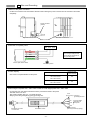
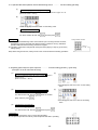
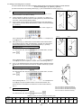
Names of Each Part
Detector connector
Encoder connector
Protective cap (Remove the cap when using.)
Option A connector
Presser foot
connector
Option B connector
1. Front side of control box
Sewing machine connector
Lever connector
Connector indication
nameplate
Front cover fixing screw
High-voltage warning plate
XC-G10-S control switch panel installation screw hole
Lever Unit
2. Back side of control box
Control switch panel
connector
Status indication LED
Motor connector
White connector for 100V
Brown connector for 200V
Power connector
3. Left side of control box
Lever
-4-
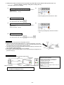
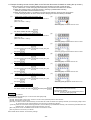
5
Installation
1. Installation of the motor
2. Installation of the control box
Table
(1) Tighten the control box onto the motor.
The direction
of the plate
3-9 holes
159
57
Encoder
cord
66
Belt hole
Bobbin
winder
(2) Insert the power cord from the motor into the connector on the
back of the control box. Insert the encoder cord from the motor
into the encoder connector on the front of the control box.
Power cord from motor
100V : White connector
200V : Brown connector
Using the hole opening pattern, open three 9mm
holes on the table. Install the motor securely
using the installation bolts, washers, spring
washers and nuts. The pattern and installation
bolts, etc., are included with the motor as
accessories.
3. Installation of the pulley
* To properly install, the protective cover A (motor side of the protective cover) must be
installed onto the motor before the pulley is installed. (Refer to "5. Installing the protective
cover”.)
Caution
Securely tighten the pulley.
Incomplete tightening may
cause malfunctions.
Select the correct pulley diameter to ensure complete use of the motor performance.
Selection of the motor pulley:
Motor pulley
Normal sewing machine speed
outer diameter (mm) =
(*)Motor speed
x
Sewing machine pulley diameter
+ 5 mm
(effective diameter)
(*) The motor speed should be set at 3,600rpm. When the motor pulley diameter is selected with the above method
and the pulley diameter is too small, select the minimum pulley in the range that the belt will not slip.
(**) Refer to page 20 for the pulley diameter to be used when using the Mitsubishi thread trimming sewing machine.
4. Mounting of the belt
Use the JIS K6323 sewing
machine belt M-type.
15mm (approx. 9.8N(1kg))
To adjust the belt tension, press down on the center of
the belt with your hand, and turn the upper and lower nuts
of the adjustment nut to increase or decrease the center
height of the motor so that the belt dips approximately
15mm.
Caution
If the belt tension is too low, the medium
and low speeds will be inconsistent, and
the stopping precision will be poor.
When too tight, the motor bearings will
deteriorate.
The protective cover A is not shown.
Adjustment nut
Caution
For safety always turn the power
switch off, before adjusting the belt.
-5-
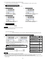
5. Installation of the protective cover (with belt slip off prevention part)
The protective cover is enclosed with the motor as an accessory.
1. Install the protective cover A onto the motor.
2. Install the pulley and attach the belt. (Refer to "3. Installing the
pulley" and "4. Mounting of the belt".)
Nut
Belt
Protective cover A
Pulley
Tightening bolt
3. Install the "belt slip off prevention part mounting plate" onto protective cover B with the following procedures.
* Change the direction of the long and short side of the attachment plate according to the motor pulley outer diameter.
(a) For motor pulley outer diameter φ55 to φ80
(b) For motor pulley outer diameter φ80 to φ125
Attachment plate
rectangle side
Attachment plate
rectangle side
Pulley outer
diameter φ55 to 80
indication scale
(front)
Pulley outer
diameter φ80 to 125
indication scale
(front)
Cross-section A-A
Cross-section B-B
(View from back of protective cover)
(View from back of protective cover)
* Set the center of the washer to the pulley diameter indication scale and tighten the bolt.
* Confirm that the belt does not contact the attachment plate.
4. Install the "protective rod" onto the protective cover B with the following steps.
* Set the protective rod to the motor pulley rotation direction and install between the belt and motor pulley.
(a) For counterclockwise rotation
(b) For clockwise rotation
Belt
Protective rod
Protective rod
Motor pulley
Protective
cover
(View from front of protective cover)
(View from front of protective cover)
* Set the center of the protective rod to the position at the center of the belt and motor pulley and tighten the bolt
Set screw
5. Set protective cover B onto protective cover A,
and tighten with the four set screws.
* Confirm that the belt and motor pulley do not
contact the protective rod.
Set screw
6. If necessary, adjust the position of the
Set screw
"protective rod" and "belt slip off prevention part
mounting plate". Securely tighten after
adjusting.
Set screw
-6-
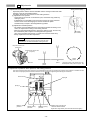
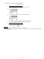
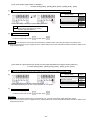
6. Installation of the position detector
Position detector
Stopper
Grounding wire
(green/yellow)
(1) The installation of the position detector will differ according
to the sewing machine model, so please consult with your
sewing machine dealer for details.
The diagram on the left shows an example of the position
detector installation.
(2) Insert the connector from the position detector into the
control box position connector.
(3) To prevent malfunctions caused by static electricity, connect
the grounding wires (green/yellow) from the position
detector onto the sewing machine head.
Caution
This can not be used with except
XC-G, XC-F and XC-E Series.
This can be installed onto
the sewing machine table
as shown here.
Control box
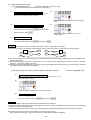
7. Connection of the Mitsubishi sewing machine and control box.
Wire the units as shown below.
Align the connector shape and direction, and securely insert it.
[View of control box from cover side]
[View of control box from box side]
Encoder
connector
Motor
connector
Lever
connector
Sewing machine
connector
Control switch panel
connector (Option)
Status indication LED
Caution
For safety purposes, always turn the power switch OFF and wait for
the status indication LED or the [PWR. OF] (displayed for approx. 10
seconds) LED display on the control switch panel to turn OFF before
connecting or disconnecting each connector.
This [PWR.OF] display is not an error.
-7-
6
Wire and Grounding
1. Insertion of the power connector
Confirm the connector form and insertion direction when inserting the power connector into the control box and insert
completely.
Power connector
(6-Pole)
Right side of control box
Back side of control box
Power connector
3-phase power
2. Connection of 3-phase power
RSTphase phase phase
Red
Ground the green (green/yellow)
wire to the grounding terminal.
Consult with an electrician for
the grounding wires.
White
Black
Green
(Green/yellow)
Cord for push-button switch
Connect to ground
3. Current capacity
Power
Use a fuse or complete breaker for the power.
Recommended
current capacity
Single phase
100 to 120V 550W
15A
200 to 240V 550W
3- phase
10A
200 to 240V 550W
4. When using the 3-phase 200 - 240V class Limiservo X with single phase 200 - 240V class
Connect the "red" and "white" lead wires from the push-button switch to the power.
The black wire is not used.
Tape it with insulation tape, etc., to insulate securely.
Always ground the green/yellow (green) grounding wire.
Green
(Green/yellow) Connect to
grounding terminal
Red
White
Connect these
lead wires to
the power.
Black
Connection connector
to control box
Push-button switch
-8-
Do not connect.
(Securely insulate by taping.)
7
Confirmation
1. Before turning switches on..........
Places to confirm
Reference
(1) Is the power and capacity suitable ?
Current capacity on page 8.
(2) Is the power voltage the same as the factory preset voltage of the
rated nameplate on the side of the control box?
Voltage value given on rated nameplate on side of control box.
XC-GMFY-20-05 : 200 to 240V
XC-GMFY-10-05 : 100 to 120V
(3) Are the connectors inserted correctly?
Insertion of the power connector on page 8.
-Power connector from push-button switch
-Motor connector
-Motor encoder connector
-Position detection connector
Connection of the Mitsubishi sewing machine
and control box on page 7.
Insertion of the position detector on page 7.
(4) Is the lead wire contacting the V belt ?
-
(5) Is the belt tension okay ?
Mounting of the belt on page 5.
(6) Are the pulley nuts securely tightened ?
Installation of the pulley on page 5.
(7) Can the sewing machine be rotated lightly by hand ?
-
2. Turn on the power..........
(1) Does the status indication LED on the control box light up in
green?
There is a problem if the LED is flickering or is lit up in red.
(2) Is the operation panel LED turning ON?
(When operation panel is connected)
Status indication LED
Operation panel
(3) Does the position detector lamp light ?
Position detection
(4) Is the sewing machine rotation direction correct? (When control switch panel is connected)
Operation panel
- For left rotation
The sewing machine rotates to
the left looking from the pulley
side. The factory setting is left
rotation.
- For right rotation
The sewing machine rotates to
the right looking from the pulley
side.
The rotation direction can be changed by pressing the [↓] key and [M] key simultaneously.
(5) Is there any heat, odors or abnormal sounds coming from the motor or control box?
Turn the power OFF and disconnect the power
plug from the socket if any heating, abnormal
odors or abnormal noise is found. Contact your
dealer immediately.
-9-
8
Adjustments
1. Adjustment of stopping position
Sewing machine pulley
Adjust this position with the detector installed onto the sewing machine and while
stopping at the UP and DOWN positions.
For safety, disconnect the connector for the sewing machine.
(1) Adjustment of UP position
-Loosen the two set screws on the detector joint, and set the stop position by
rotating by hand.
-If adjustment is not possible by turning the joint, loosen the cross-recessed
screw A shown of the following figure, and turn all detector plates
simultaneously to adjust to the designated stop position.
(2) Adjustment of DOWN position
-The relation of the DOWN position and UP position will differ according to the
model, so adjust this according to the sewing machine.
-When changing the DOWN position, remove the detector cover, and turn only
the red detector plate to adjust to the designated stop position.
(The cross-recessed screw A does not need to be loosened at this time.)
-Always replace the cover after adjustment.
Set screws
(two screws)
Caution
Refer to the sewing machine instruction manual when
adjusting for use with the Mitsubishi sewing machine.
UP position detector disc
(black)(inner)
UP
position
DOWN position detector disc
(red)(outer)
180˚
180˚
Screw A
UP
position
DOWN
position
DOWN
position
(The factory setting of the clearance from the
DOWN position to UP position is approx. 180)
2. Adjustment of pedal toe down pressure, and heeling pressure
The spring A pressure (toe down pressure) can be adjusted in five levels by changing the position spring A whitch is hooked onto the
lever unit. The spring B pressure (heeling pressure) can be adjusted by tightening or loosening the screw bolt.
Screw bolt
Spring B
Spring A
Minimum spring
pressure
Medium spring
pressure
Maximum spring
pressure
- 10 -
Installation hole of the joint rod
Left side: Standard stroke
Right side: Large stroke (The movement becomes lighter)
3. Adjustment of operation speed
Adjustment of
each speed
L
-
4000
250
T
-
200
H
N
V
S
Page25 “To change the maximum speed”
1700
1700
250
Adjust between the low speed [L] and high speed [H] using
the [C] and [D] keys on the operation panel.
-
It is possible to
adjust between
0 and 99.%
[C]key
Rotation speed
Maximum speed
Low speed
Thread trimming
speed
Start tack speed
End tack speed
Slow start speed
Operation speed
Factory setting
(speed)
Reference
Maximum speed [H]
Low speed [L]
[D]key
99
0
Adjustment
range with
the [C] key
and [D] key.
Caution
No matter how large the motor pulley diameter is, the speed
will not rise higher than the maximum speed H and the speed
set with the [C] key and [D] key.
- 11 -
9
Changing the solenoid voltage and output voltage
1. To change solenoid voltage DC24V/DC30V
Control box side
To change solenoid voltage from 24V to 30V
(1) Remove the front cover from the control box.
(2) Reconnect the connector inserted in JP1 on the PCB to the
30V side.
(3) Set the cover to the original position after change.
To change solenoid voltage from 30V to 24V
(1) Remove the front cover from the control box.
(2) Reconnect the connector inserted in JP1 on the PCB to the
24V side.
(3) Set the cover to the original position after change.
Control box cover side
Wait at least 10 minutes after
turning the power switch OFF
before opening the control box.
24V setting (factory setting)
30V setting
Control box side
2. Changing the output voltage between 0VDC and 5VDC
(1) Remove the control box cover.
(2) Change the output voltage 5/12VDC with the jumper JP3
and JP4 on the front cover PCB as shown on the right.
Change the output voltage 0/5VDC with the jumper JP5 on
the front cover PCB.
(3) The output voltage can be changed by reconnecting the
connector as shown on the right.
(4) The factory setting
Connector
JP3
JP4
JP5
factory
setting
+12V
+5V
0V
Connector (Pin No.)
No.3 pin of the option A
No.7 pin of the option B
No.10 pin of the sewing machine
Control box cover side
(5) After change, always set the cover to the control box.
0V setting
5VDC setting
12VDC setting
Do not change the JP1,JP2 and
JP6 from the factory setting.
Wait at least 10 minutes after
turning the power switch OFF
before opening the control box.
- 12 -
5VDC setting
10
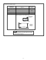
Operation of the Control Switch Panel Keys(When using XC-G10 type operation
1. Displays during normal mode and functions of each key
When the power supply switch is turned ON, the rotation direction will display on the LED.M shown below.
When the rotation direction is not displayed on LED.M, press the [↓] key any time.
This state is called the normal mode, and the following keys can be operated.
LED.M
The rotation direction of the sewing machine is displayed.
The rotation direction can be changed with the [↓]+[M] keys.
Parameter setting key
Use these keys to switch to the program
mode, and to start the number call function.
LED.A~D
The state of the [A] to [D] keys
function setting is shown.
Parameter
Setup
[↑] (Up), [↓] (Down) keys
The validity of the start and end
tacking switch, the type of stitch,
the number of stitches, the preset
stitching and backtacking, etc.,
can be set.
[C] key, [D] key
The speed at which the pedal
is fully toed down is set.
Enter key
Use this key to set the various
setting values when using the
number call function.
Shift
Shift key
When using the [A] to [D] keys in the [-] (minus) state,
press the [A] to [D] keys while holding down this Shift
Note
This above keys can be operated only when
the rotary display is shown on the LED.M.
(Excluding the Enter key or Shift key)
[B] key
This is used to start sewing with a slow start. After the power is turned
ON and after thread trimming, the sewing will start with a slow start.
[A] key
1 position and 2 position can be selected for
the needle position during stopping.
Refer to "3. How to use the normal mode" for details.
2. Selection of each mode
The modes can be changed from the normal mode to various program modes and various basic functions and application functions set with
this control switch panel.
(Refer to the Technical Documents for details on each mode's function.)
(1) Types of program mode
Tacking setting, preset stitching setting, pattern No. selection modes
Normal mode
(The rotation direction is
displayed on LED.M)
Program mode [P] The setting to often use 1
*Sewing machine, etc.
Program mode [A] The setting to often use 2
*Servo motor, etc.
Program mode [B] The setting to often use 3
*Counter/Speed display, etc.
Program mode [C] Applied function [C] setting mode
* Customizing, etc.
Program mode [D] Tacking setting mode
Program mode [E] H/W checking mode * The input/output function can be checked, and
the error statue during a fault can be investigated.
Program mode [I] Save mode of the setting data
Program mode [R] Reset/returning to original data.
* The state set with each program mode can be returned to the original settings (factory
settings).
Program mode [1] Simple setting mode for Mitsubishi thread trimming sewing machine.
Program mode [2] Simple setting mode for chain stitch sewing machine.
Program mode [3] Simple setting mode for other lock stitch sewing machine.
Caution
A program mode cannot be entered from an other program mode.
Always return to the normal mode once before changing the program mode.
Note that when the program mode is selected with the "Direct number call function", a selection
exceeding the program mode type can be made with the number selection.
- 13 -
(2) Selection of each program mode from the normal mode.
Mode name
Key operation
Return to the
normal mode
Digital display
Tacking type
setting mode
Press the [↑] key one time from the
normal mode.
No. of tacking stitch
setting mode
Press the [↑] key two times from
the normal mode.
*The tacking setting mode will be
entered.
*The tacking stitches setting mode will
be entered.
Press the [↓]
key one time.
Press the [↓]
key two times.
Note) Skipping about this menu at the time of pattern No.=4.
*The preset stitching setting mode
Preset stitching
setting mode
Press the [↑] key three times from
the normal mode.
Pattern No.
selection mode
Press the [↑] key four times from
the normal mode.
*The pattern No. selection mode will be
*The display will flicker.
Program mode [P]
While holding down the
[↓] key, press the [↑] key
for 2 seconds or more
from the normal mode.
Program mode [A]
While holding down the
[↓] key, press the [A] key
for 2 seconds or more
from the normal mode.
Program mode [B]
While holding down the
[↓] key, press the [B] key
for 2 seconds or more
from the normal mode.
Program mode [C]
While holding down the
[↓] key, press the [C] key
for 2 seconds or more
from the normal mode.
Program mode [D]
While holding down the
[↓] key, press the [D] key
for 2 seconds or more
from the normal mode.
Program mode [I]
Program mode [R]
entered.
*The program mode [P] will be entered.
Switch the function item with the [↓] or
[↑] key.
The mode can also be selected with the "Direct number call operation".
(Refer to the next page.)
Program mode [E]
Note) Skipping about this menu at the time of pattern No.= A to H.
*The display will flicker.
*The program mode [A] will be entered.
Switch the function item with the [↓] or
[↑] key.
*The display will flicker.
*The program mode [B] will be entered.
Switch the function item with the [↓] or
[↑] key.
*The display will flicker.
*The program mode [C] will be entered.
Switch the function item with the [↓] or
[↑] key.
*The display will flicker.
*The program mode [D] will be entered.
Switch the function item with the [↓] or
[↑] key.
While holding down the
[↓] key , press the [A] key
and the [↑] key for 2
seconds or more from
normal mode.
While holding down the [↓] key,
press the [↑] key and the [B] and
the [C] key for 2 seconds or more
from normal mode.
While holding down the [↓] key,
press the [B] and the [C] key for 2
seconds or more from normal
mode.
*The display will flicker.
*The program mode [E] will be entered.
Switch the function item with the [↓] or
[↑] key.
*The display will flicker.
*The program mode [I] will be entered.
*The display will flicker.
*The program mode [R] will be entered.
While holding down the [↓] key,
press the [A] and the [B] key for 2
seconds or more from normal
mode.
*The display will flicker.
Program mode [1]
Simple setting
Program mode [2]
Simple setting
While holding down the [↓] key,
press the [C] and the [D] key for 2
seconds or more from normal
mode.
*The display will flicker.
Program mode [3]
Simple setting
While holding down the [↓] key,
press the [A] and the [D] key for 2
seconds or more from normal
mode.
*The display will flicker.
*The program mode [1] will be entered.
Switch the function item with the [↓] or
[↑] key.
*The program mode [2] will be entered.
Switch the function item with the [↓] or
[↑] key.
Press the [↓]
key three
times.
Press the [↓]
key four times.
Press down
[↓] key, press
[↑] key.
Press down
[↓] key, press
[↑] key.
Press down
[↓] key, press
[↑] key.
Press down
[↓] key, press
[↑] key.
Press down
[↓] key, press
[↑] key.
Press down
[↓] key, press
[↑] key.
Press [D] key
for 2 seconds
or more.
[*1]
Press [D] key
for 2 seconds
or more.
[*1]
Press [D] key
for 2 seconds
or more.
[*1]
Press [D] key
for 2 seconds
or more.
[*1]
Press [D] key
for 2 seconds
or more.
[*1]
*The program mode [3] will be entered.
Switch the function item with the [↓] or
[↑] key.
[*1] To return to the normal mode without executing each function in mode [I], [R], [1], [2]or [3], press the [↓] and [↑] keys simultaneously.
- 14 -
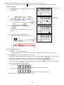
(3) Direct number call function
(Directly selecting program mode function item from normal mode)
The number of each function listed in section "13 List of functions" can be directly designated to call the function item.
[Basic procedures]
(1)
(1000th) (100th) (10th)
(2)
(1st place)
、
、
、and
Press the
display the target function item number.
(The number
selection mode)
keys to
(To use the above "+/-" key as a "-" key, press
(3)
(The normal mode)
Parameter
Setup
Press
in the normal mode and switch to the number
selection mode.
to
Shift
while holding down
.)
When the target function item number appears,
press
.
(Number 33 as shown on page 38 is called out in this
example.)
(4)
This completes calling of the function item.
(In this example, function name [AT.] was called out.)
13
Function list
[Miscellaneous/Precautions]
- Press
Parameter
Setup
to return to the normal mode.
The display will return in the order of [Function item] → [number selection mode] → [normal mode].
- Press
after changing the setting for each function item.
The display LED will flicker, and after the changed items are set, the mode will change to the [number selection mode].
(The changed items will be canceled if the normal mode is returned to without pressing
.)
- The display LED will flicker if a function number that does not exist is displayed. Select a number that exists.
- The range of the number designation can be limited as shown below by pressing
Parameter
Setup
, entering the [number selection
or
key.
mode] and then pressing the
(1) Selection of number for each mode (P, A, B, C...)
(Selection can be made in A mode range)
(2) Selection of all mode numbers
(Selection can be made in all mode ranges)
* Refer to the status transition diagram given on the next page.
- 15 -
Status transition diagram (Direct number call operation)
Normal mode
Parameter
Setup
Parameter
Setup
Number call mode
Number selection mode
+
Press
simultaneously
: Cancels changed
value
Select in all mode ranges
Change number with
"+" and "-" keys
Select in [P] mode range
Each function item
Change number with
"+" and "-" keys
Select in [A] mode range
:Sets changed value
Change number with
"+" and "-" keys
Parameter
Setup
:Cancels changed value
・
・
・
Possible to select A to S mode
Select in [S] mode range
Change number with
"+" and "-" keys
3. Using the normal mode
Speed adjustment
The operation speed will drop when the
[C] key is pressed.
If the [D] key is pressed, the operation
speed will increase when the pedal is
pressed down to the fullest.
The speed ratio is displayed with the two
digits LED.C and LED.D, and can be set in
the range of 0 to 99.
Changing between position 1 and position 2
The position can be changed between position 1 and
position 2 with the [A] key. The needle position
(position 1/position 2) when stopping can be
changed. Position 1 and position 2 are indicated with
LED.A.
When position 1 is set, the needle stops at the UP
position.
When position 2 is set, the needle stops at the
DOWN position, and moves to and stops at the UP
position after the thread is trimmed.
Slow start ON/OFF
Slow start can be turned ON or OFF with
the [B] key.
Turn this function ON to start stitching with
slow start.
Stitching will start slowly after the power is
turned ON or after the thread is trimmed.
The slow start ON/OFF state is indicated
with LED.B.
indicates position 1.
indicates OFF.
indicates position 2.
indicates ON.
- 16 -
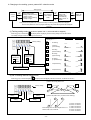
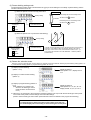
4. Changing to the tacking, preset, pattern NO. selection mode
Tacking mode
[↑]key
ON
Normal
mode
[↓]key
ON
Tacking setting mode
* Setting of the start tacking
validity and type
* Setting of the end tacking
validity and type
[↑]key
[↑]key
ON
ON
No. of tacking
stitch setting
mode
[↓]key
ON
[↓]key
ON
Preset stitching
setting mode
* Setting of the
preset stitching
validity and No. of
stitches
[↑]key
ON
Pattern No.
selection
[↓]key
ON
Note) At the time of pattern No.=4 (continuous tack), the tacking setting mode will be skipped.
At the time of pattern No.=A to H (program stitching), the preset stitching mode will be skipped.
[↑]key ON
(1) Tacking setting mode (At the time of pattern No.=4, this mode will be skipped.)
When the [↑] key is turned ON,
will display above the [M] key, and the tacking setting mode will be entered.
The validity and type of start and tacking can be set here.
start tacking
Setting of tacking type
< Display ex. >
Factory setting
Setting of start
tacking validity
<Display ex.>
: No tacking
Setting of end
tacking validity
<Display ex.>
: Valid
: Valid
: Invalid
: Invalid
end tacking
:
V tacking
(Once tacking)
:
N tacking
(Double tacking)
:
M tacking
(Triple tacking)
:
W tacking
(4 repeat tacking)
: 5 repeat tacking
Setting of end tacking type
Setting of start tacking type
: 6 repeat tacking
(2) No. of tacking stitches setting mode
When the [↑] key is turned ON again,
will display above the [M] key indicator, and the No. of stitches can be set.]
(1) When the except pattern No.4
Factory setting
START
END
B
A
No. of stitches A
setting.
No. of stitches B
setting.
No. of stitches D
setting.
C
D
(2) When the pattern No.4 (continuous tack stitching)
B
No. of stitches C
setting.
A
D
C
Each setting value can be changed from 0 to 9
stitches, A,B,C,D,E,F stitches.
- 17 -
'A' means 10 stitches
'B' means 11 stitches
'C' means 12 stitches
'D' means 13 stitches
'E' means 14 stitches
'F' means 15 stitches
(3) Preset stitching setting mode
The preset stitching setting mode is entered when the [↑] key is turned ON again. The validity of preset stitching and the
number of stitches N can be set.
(1) When the pattern is the time except pattern No.4
Start tacking
S
Factory setting
Start tacking that is in the tacking mode
N stitches
will start at the S position.
End tacking that is in the tacking mode
Setting of preset stitching
<Display ex.>
E
Setting of No. stitches N
(0 to 9999 stitches)
will start at the E
position.
End tacking
: Valid
: Invalid
B
(2) When the pattern is No.4 (continuous tack stitching)
D
Factory setting
A
C
N
Setting of continuous tack
stitching validity
<Display ex.>
Setting of No. times N
(0 to 9999 stitches)
: Valid
: Invalid
In the No. of times (N) setting is N=3, the stitching will be in the order of
A,B and C. If the setting is N=5, the stitching will be in the order of
A,B,C,D,C. If the N is 6 or more, the order will be A,B,C,D,C,D.....(If
N=0, tacking will continue in the order ABCDCD... while the pedal is
pressed down.)
(4) Pattern No. selection mode
When the [↑] key is turned ON again, and the pattern No. selection mode will be entered. Selecting of preset stitching setting (pattern 1 to
3), continuous tack stitching (pattern 4), program stitching (pattern No. A to H).
(1) Display of preset stitching
(Pattern 1 to 3)
Display of pattern 1.
When pattern 2 or 3, display show 2
or 3.
(2) Display of continuous tack stitching
(Pattern 4)
(3) Display of program stitching (Pattern A
to H)
(Note: Patterns A to H appear only
when the XC-G500 type control
panel has been connected even
once.)
Display of pattern A
When pattern B, C, D, E, F, G or H,
display show B, C, D, E, F, G or H.
a. Patterns A to H correspond to the programs and teaching patterns A to H input with the XC-G500 type control panel.
The control switch panel is used to change and confirm the settings.
(Refer to the XC-G500 type control switch panel instruction manual for details on the program and teaching.)
Caution
For safety purposes, always turn off the power switch and confirm to
turn off the display when connecting or disconnecting the control panel.
- 18 -
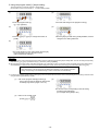
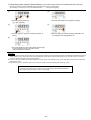
5. Using the program mode [1] simple setting
To set the settings to a specific machine in simple setting.
(For example, to set to "LU2-4410-B1T" ... Function setting [410B])
(1)
(2)
*Enter the program mode [1].
([↓] + [A] + [B] keys)
*The mode will change to the program mode [1].
(3)
(4)
*Press the [↓] key or [↑] key to change the function to
[410B].
*When the [D] key is held down, [410B] will flicker, and the
changes to the setting will be set.
(5)
*The mode will return to the normal mode when the [D]
key is held down over two seconds or more.
(This completes the settings.)
Description
A. Select the function name corresponding to the sewing machine model from the following simple setting table. The item will change sequentially
each time the [↓] or [↑] key is pressed in step (3). (The factory setting is [280M].)
B. After selecting the function name, holds down the [D] key over 2 seconds or more. The function name's set speed and function setting will be
set automatically. To return to the normal mode without setting the function name here, press the [↑] key while holding down the [↓] key.
Caution
When this function is set, all previously set details will be cleared. The set speed and function
setting corresponding to the selected sewing machine model will be set automatically.
C. The set function settings (simple setting value (type)) can be confirmed with the function name corresponding to the set sewing machine model
using the following procedures (E mode).
(1)
Call out the program mode [E] function [T].
(The mode can also be called out directly with
a number[772]. Refer to pages 14 to 16.)
(2)
The function name corresponding to the set sewing
machine model will appear.
(For example when [3750] is set.)
(3)
Return to the normal mode.
(Press [↓]+[↑] or
)
- 19 -
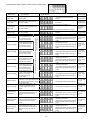
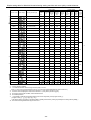
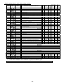
Simple setting table for Mitsubishi thread trimming sewing machine and motor pulley outside diameter.
Speed setting
Function name Digital display
*3
*8
*8
*3
*4
*5
*6
*7
*8
End
tacking
speed
(V)
D mode
tack
alignment
(BM)
Motor
pulley
A mode A mode
outside
weak
gain
brake selection diameter
(mm)
(BK)
(GA)
LS2-1280-M1T (W)
4000
250
200
1700
1700
OFF
OFF
L
280H
LS2-1280-H1T(W)
3000
250
200
1200
1200
OFF
OFF
L
280B
LS2-1280-B1T
3000
250
200
1200
1200
OFF
OFF
L
380M
LS2-1380-M1T(W)
4000
250
200
1700
1700
OFF
OFF
L
380H
LS2-1380-H1T(W)
3000
250
200
1200
1200
OFF
OFF
L
380B
LS2-1380-B1T
3000
250
200
1200
1200
OFF
OFF
L
210M
LS2-2210-M1T(W)
4000
250
200
1700
1700
OFF
OFF
L
230M
LT2-2230-M1TW
3700
250
175
1200
1200
OFF
OFF
H
230B
LT2-2230-B1T
3000
250
175
1200
1200
OFF
OFF
H
250M
LT2-2250-M1TW
3000
250
175
1200
1200
OFF
OFF
H
250B
LT2-2250-B1T
3000
250
175
1200
1200
OFF
OFF
H
3310
LY2-3310-B1T
2000
250
225
700
700
ON
OFF
H
3319
LY2-3319-B1T
2000
250
225
700
700
ON
OFF
H
3750
LY2-3750-B1T
2000
250
200
700
700
ON
OFF
L
6840
LY3-6840-B0T
2000
250
150
700
700
ON
OFF
H
6850
LY3-6850-B1T
2000
250
150
700
700
ON
OFF
L
410B
LU2-4410-B1T
2000
250
175
700
700
ON
OFF
L
412B
LU2-4412-B1T
2000
250
175
700
700
ON
OFF
L
430B
LU2-4430-B1T
2000
250
175
700
700
ON
OFF
L
4650
LU2-4650-B1T
3000
250
175
700
700
ON
OFF
L
4652
LU2-4652-B1T
3000
250
175
700
700
ON
OFF
L
4710
LU2-4710-B1T
3000
250
175
700
700
ON
OFF
L
4730
LU2-4730-B1T
2500
250
175
700
700
ON
OFF
L
LX2-630-M1
800
280
160
500
500
ON
ON
L
65
LS2-1280-M1T(W)
5000
250
200
1700
1700
OFF
OFF
H
110
280E
*1
*2
High
speed
(H)
Function setting
Start
tacking
speed
(N)
280M
630
*4
Sewing machine type
Thread
Low speed trimming
speed
(L)
(T)
FL
*5
5000
250
200
1700
1700
OFF
OFF
L
N
*6
5000
250
200
1700
1700
OFF
OFF
L
LOAD2
*7
LOAD1
*7
Factory setting is [280M].
The effective diameter of the sewing machine pulley is 70 mm.
(Note : In case of LY2-3310/3319/3750 is 80 mm, LU2-4410/4412/4430/4650/4652/4710/4730 is 85 mm.)
A function name is displayed in order to the direction of ↓ every time it presses a [↓] key.
A function name is displayed in order to the direction of ↑ every time it presses a [↑] key.
For sewing machine with foot lifter, without thread trimmer.
For needle positioner.
It is possible to load the saved setting data by the function of [SAVE*] in the program mode [ I ].
( Program mode [ I ] : [↓]+[↑]+[B]+[C] key )
( The factory setting of [LOAD1] is the setting data of [412B] and the factory setting of [LOAD2] is the setting data of [280M]. )
The short remaining thread trimming function is set.
- 20 -
*1
85
*2
65
85
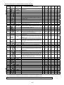
6. Using the program mode [2] simple setting (for chain stitch trimming machine)
To set the function for chain stitch sewing machine in simple setting.
(Ex. To set for the VC2800, VC3800 class, "YAMATO") .......... Function setting [YU4]
(1)
(2)
*Enter the program mode [2].
([↓] + [C] + [D] keys)
*The mode will change to the program mode [2].
(3)
(4)
*Press the [↓] key or [↑] key to change the function to
[YU4].
*When the [D] key is held down, [YU4] will flicker, and the
changes to the setting will be set.
(5)
*The mode will return to the normal mode when the [D]
key is held down over two seconds or more.
(This completes the settings.)
Description
A. Select the function that corresponds to the sewing machine model for "Simple setting table for chain stitch sewing machine" on the page 22.
After selecting the function name, holds down the [D] key over 2 seconds or more. The function name's set speed and function setting will be
set automatically (Refer to the simple setting table for "YAMATO" on page 22.)
B. To return to the normal mode from the [YU4] display, press the [↑] key while holding down [↓]. In this case, [YU4] will not be set, and the last
settings will be used.
C. Each time the [↓] key is pressed in step (3), the function will change in order from [YU2], [YU3], [YU4].....[JMH].
Caution
To use this mode, please ask your dealer or look at "TECHNICAL INFORMATION MANUAL"
about simple setting, I/O signal, Junction wiring in detail.
- 21 -
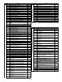
Simple setting table for chain stitch sewing machine
Function
name
*1
Digital
display
Sewing machine
maker
Model name of sewing machine and device
High
speed
(H)
Thread Start con- End conLow
speed trimming densed densed
speed speed
speed
(L)
(N)
(V)
(T)
YU2
YAMATO
VC2600, VC2700 class Solenoid-operated under thread trimmer
2
6000
200
200
1400
1400
YU3
YAMATO
VC2600, VC2700 class Air-operated under thread trimmer with air wiper
2
6000
200
200
1400
1400
YU4
YAMATO
VC3845P,2845P,2840P class Air-operated under thread trimmer with air
wiper
2
6000
200
200
1400
1400
YU5
YAMATO
Solenoid-operated under thread trimmer with solenoid wiper
W(T) series /UT device
Electric under thread trimmer
W(T) series /UT device
Pneumatic under thread trimmer with pneumatic top cover thread trimmer
2
6000
200
200
1400
1400
1
6000
200
200
1400
1400
1
6000
200
200
1400
1400
FW series /UT device
Electric under thread trimmer
FW series /UT device
Pneumatic under thread trimmer
1
4500
200
200
1400
1400
1
4500
200
200
1400
1400
W674/UT device
Super tack
W(T)562-82/UT device
Angled stitch
Electric under thread trimmer
W(T)562-82/UT device
Angled stitch
Pneumatic under thread trimmer with pneumatic top cover thread trimmer
1
4000
200
200
1400
1400
1
6000
200
200
1400
1400
1
6000
200
200
1400
1400
1
6000
200
200
1400
1400
1
6000
200
200
1400
1400
NO1
PEGASUS
NO1A
PEGASUS
NO2
PEGASUS
NO3
PEGASUS
NO3A
PEGASUS
NO4
PEGASUS
NO5
PEGASUS
NO5A
PEGASUS
NO6
PEGASUS
NO7
PEGASUS
NO7A
PEGASUS
Do not use !!
Do not use !!
W(T)600,200 series /UT device
condensed stitch
Electric under thread trimmer
W(T)600,200 series /UT device
condensed stitch
Pneumatic under thread trimmer with pneumatic top cover thread trimmer
NO8
PEGASUS
NOD
PEGASUS
W(T) series /SL device
Stitch lock
Pneumatic under thread trimmer
1
6000
200
200
1400
1400
NOF
PEGASUS
EX/BL500,600 series
1
6000
200
200
1400
1400
PFL
PEGASUS
For sewing machine with foot lifter, without thread trimmer
1
6000
200
200
1400
1400
PN
PEGASUS
For needle positioner
1
6000
200
200
1400
1400
KA1
KANSAI
M, RX series
2
6000
250
250
1400
1400
KA2
KANSAI
D series
Automatic thread trimmer with air wiper
2
6000
250
250
1400
1400
KA3
KANSAI
F series
Air-operated under thread trimmer with air wiper
2
6000
250
250
1400
1400
KA4
KANSAI
DX series
2
6000
250
250
1400
1400
2
4000
200
200
1400
2999
2
5500
200
200
1400
2999
2
4000
200
200
1400
2999
2
6000
200
200
1400
1400
Do not use !!
Automatic thread trimmer with solenoid wiper
Air-operated under thread trimmer with air wiper
UN1
UNION SPECIAL 33700, 34500 class
UN2
UNION SPECIAL 34800skcc class
UN3
Solenoid-operated under thread trimmer
Solenoid-operated under thread trimmer
34700 class Push and Pull air-operated under thread trimmer with air
UNION SPECIAL wiper
U345
Do not use !!
U346
Do not use !!
U348
Do not use !!
U347
Do not use !!
U160
Do not use !!
U16
Do not use !!
U362
Do not use !!
UFCW
*2
Needle
position
Do not use !!
BR1
BROTHER
FD3, FD4 series
RM1
RIMOLDI
----
1
6000
200
200
1400
1400
SRB1
SIRUBA
----
2
6000
200
200
1700
1700
JMH
JUKI
2
5500
200
200
1700
1900
MH-481-4-4, MH-484-4-4 class
*1
A function name is displayed in order to the direction of [↓] every time it presses a [↓] key.
*2
A function name is displayed in order to the direction of [↑] every time it presses a [↑] key.
Note : Please refer to the "TECHNICAL INFORMATION MANUAL" for the Junction wiring, I/O signals and details.
- 22 -
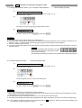
7. Using the program mode [3] simple setting (for lock stitch trimming machine except Mitsubishi sewing machine)
To set the function for DÜ RKOPP ADLER thread trimming sewing machine in simple setting
(For example, to set for the 271 class, "DÜ RKOPP ADLER") .......... Function setting [D271]
(1)
(2)
*Enter the program mode [3].
([↓] + [A] + [D] keys)
*The mode will change to the program mode [3].
(3)
(4)
*Press the [↓] key or [↑] key to change the function to
[D271].
*When the [D] key is held down, [D271] will flicker, and
the changes to the setting will be set.
(5)
*The mode will return to the normal mode when the [D]
key is held down over two seconds or more.
(This completes the settings.)
Description
A. Select the model name that corresponds to the sewing machine model for the simple setting values for the DÜRKOPP ADLER thread trimming
sewing machine on the "Technical manual". After selecting the function name, holds down the [D] key over 2 seconds or more. The function
name's set speed and function will be set automatically.
B. To return to the normal mode from the [D271] display, press the [↑] key while holding down [↓]. In this case, [D271] will not be set, and the last
settings will be used.
C. Each time the [↓] key is pressed in step 3, the function will change in order from [D697], [D271], [D273].....[750].
Caution
To use this mode, please ask your dealer or look at "TECHNICAL INFORMATION MANUAL"
about simple setting, I/O signal, Junction wiring in detail.
- 23 -
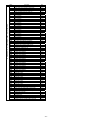
Simple setting table for thread trimming sewing machine
Function
name
*1
Thread
Start
End
Low
tacking tacking
speed trimming
speed
speed speed
(L)
(T)
(N)
(V)
Needle
position
High
speed
(H)
697-15000 class
2
1500
250
150
700
700
271-14000,272-14000 class
2
3000
170
250
1500
1500
Sewing machine
maker
Model name of sewing machine and device
273-14000,274-14000 class
2
3000
170
250
1500
1500
B715
DÜRKOPP
ADLER
DÜRKOPP
ADLER
DÜRKOPP
ADLER
BROTHER
DB2-B705,DB2-B707,DB2-B715 class
2
4300
215
215
1800
1800
B716
BROTHER
DB2-B716-?,DB2-B716-1,DB2-B716-?,DB2-B716-5 class
2
3500
215
215
1800
1800
B737
BROTHER
DB2-B737-1,DB2-B737-3,DB2-B737-5 class
2
4000
215
215
1800
1800
B740
BROTHER
DB2-B746-5,DB2-B746-7,DB2-B746-8,DB2-B747-5,DB2-B7485,DB2-B748-7 class
2
2000
215
215
1800
1800
B757
BROTHER
DB2-B757 class
2
5000
215
215
1800
1800
B770
BROTHER
DB2-B772,DB2-B774,DB2-B7740,DB2-B778 class
2
4500
215
215
1800
1800
B790
BROTHER
DB2-B790,DB2-B791-3,DB2-B791-5,DB2-B7910-3,DB2-B7910
-5,DB2-B792,DB2-B793-403,DB2-B795,DB2-B798 class
2
3500
215
215
1800
1800
B830
BROTHER
DB2-B837,DB2-B838 class
2
3000
215
215
1800
1800
BLT
BROTHER
LT2-B841-1,LT2-B841-3,LT2-B841-5,LT2-B842-1,LT2-B842-3,L
T2-B842-5,LT2-B845,LT2-B8450,LT2-B8480,LT2-B847,LT2-B8
48,LT2-B872,LT2-B875,LT2-B8750 class
2
3000
185
185
1000
1000
BLZ
BROTHER
LZ2-B852,LZ2-B853,LZ2-B854,LZ2-B856,LZ2-B857 class
2
3000
185
185
1800
1800
J500
JUKI
DDL-500,DMN-5420NFA-6-WB class
2
5000
200
200
1700
1900
2
4000
200
200
1700
1900
2
4000
200
200
1700
1900
2
4200
200
200
1700
1900
2
2000
200
200
1700
1900
1
2300
200
200
1700
1900
DDL-5560NL-6,LU-1114-5,LU-1114-6,LZH-1290-6 class
2
2800
200
200
1700
1900
D697
D271
D273
J505
JUKI
J555
JUKI
JDL
JUKI
JDU
JUKI
JLH
JUKI
JLU1
JUKI
JLU2
JUKI
DDL-505,DDL-505A,DDL-506,DDL-506A,DDL-506E,DDL-5605,DDL-5600,DLU-5494NBB-6-WB,PLW-1245-6,PLW-1246-6,P
LW-1257-6,PLW-1264-6,PLW-1266-6 class
DDL-555-2-2B,DDL-555-2-4B,DDL-555ON,DDL-5570,DDL-557
1,DDL-5580 class
DLD-432-5,DLD-436-5,DLM-5400N-6,DLM-5400-6,DLN-415-5,
DLN-5410N-6,DLN-5410-6,DLU-450,DLU-490-5,DLU-491-5,DL
U-5490BB-6-OB,DLU-5490BB-6-WB,DLU-5490N-6,DMN-5305,DMN-531-5 class
DNU-241H-5,DNU-241H-6,DSC-244-6,DSC-244V-6,DSC-2455,DSC-245-6,DSC-246-6,DSC-246V-6,DSU-142-6,DSU-144-6,
DSU-145-5,DSU-145-6,DU-141H-4,DU-141H-5,DU-141H-6,DU
-161H-6 class
LH-1172,LH-1180-5,LH-1182-5,LH-1150,LH-1152,LH-1160,LH-1
162 class
LU-2210-6-0B class
2
3500
200
200
1700
1900
2
3500
200
200
1700
1700
T100
TOYOTA
AD1012,AD1012B,AD1012G,AD1013,AD1013A,AD1013G,AD1
020,AD1102,AD1102B,AD1102G,AD1103,AD1103A,AD1202,A
D1203,AD1204S,AD1205,AD1205S,AD1212G,AD1213,AD220
0,AD5010S class
T157
TOYOTA
AD157,AD157G class
2
4000
200
200
1700
1700
AD158,AD158-2,AD158-22,AD158A-3,AD158A-32,AD158B-2,
AD158B-22,AD158G-2,AD158G-22,AD158-3,AD158-32 class
AD3110,AD3110P,AD320-2,AD320-22,AD320-202,AD331,AD3
310,AD3310P,AD332,AD340-2,AD340-22,AD340-202,AD340B2,AD340B-22,AD340B-202,AD341-2,AD341-22,AD341-202,AD
345-2,AD345-22,AD345-202,AD352 class
2
3500
200
200
1700
1700
2
1900
200
200
1700
1700
1700
T158
TOYOTA
T300
TOYOTA
2
4000
250
180
1700
SLH-2B
2
570
100
100
1700
1700
SINGER
457 Wiper
2
4000
250
160
1500
1500
457F
SINGER
457 Thread pull
2
4000
250
160
1500
1500
591
SINGER
591, 1591
2
4000
250
200
1500
1500
211A
SINGER
211A
2
2300
200
180
1000
1000
212A
SINGER
212A
2
3500
200
180
1000
1000
U639
*2
Digital
display
UNION SPECIAL Class 63900 Solenoid-operated needle feed under trimmer
SLH2
SEIKO
457G
411U
SINGER
411U
2
4000
250
180
1500
1500
412U
SINGER
412U
2
4500
250
180
1500
1500
591V
SINGER
591V
2
4000
250
200
1500
1500
691A
SINGER
1691D250
2
4000
250
200
1500
1500
691B
SINGER
1691D210, 1691D200
2
4000
250
200
1500
1500
750
SINGER
750
2
4500
250
215
1500
1500
*1
*2
A function name is displayed in order to the direction of [↓] every time it presses a [↓] key.
A function name is displayed in order to the direction of [↑] every time it presses a [↑] key.
Note :
Please refer to the "TECHNICAL INFORMATION MANUAL" for the Junction wiring,
- 24 -
I/O signals and details.
11
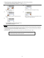
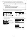
Example of setting the program mode
1. To change the maximum speed (Ex. to change to 3500 rotations) ............ Function setting [H.3500]
(1)
Call out the program mode [P] function [H].
(This can be called with mode call or direct number call. Refer to pages 14 to 16.
(Direct call number = "0000") )
(2)
Press the [+] and [-] keys ([A], [B], [C], [D]), and set to "3500".
(3)
Entering the normal mode
For mode call: [Ļ] + [Ĺ]
For direct number call: Set with
and then press
.
Description
A. The setting range of the maximum speed is 0 to 8999 rotations.
B. By pressing each of the [A], [B], [C] and [D] keys, the setting value will change between 0 and 9. (However, the [A] key is only
between 1 and 8.) To lower the value, press the [A], [B], [C], [D] keys while holding down the [Shift] key.
C. The factory setting is [4000 rotations].
D. Low speed, thread trimming speed, start tacking speed, end tacking speed, medium speed and slow start speed can be set in
the same manner.
Memo
The LED.D dot will flicker after the setting is changed.
This indicates that the factory setting value (default
value) has been changed.
(This explanation regarding the flickering dot is omitted in the following explanations.)
2. To set the standing work type .......Function setting [AT.ON]
(1)
Call out the program mode [P] function [AT].
(This can be called with mode call or direct number call. Refer to pages 14 to 16.
(Direct call number = "0033"))
(2)
*Press the [D] key and set to "ON" for the setting value.
(3)
Entering the normal mode
For mode call: [Ļ] + [Ĺ]
For direct number call: Set with
and then press
.
Description
A. This is used for high speed operation during standing operations.
When setting it to turning ON, it operates at the speed with the rate which has been set with the [C] and the [D] key in normal
mode regardless of the pedal stepping quantity.
B. This setting is first priority to the key switch [AUTO] of control switch panel (XC-G500 type).
C. The setting value will alternate between [OF] and [ON] with each press of the [D] key in step (2). (The factory setting is [OF])
Note : The switches for standing operation are connected as shown on 14-2-(2) page 43. Be sure to set the function [PDS] to ON
in the program mode [C] as shown on page 43.
- 25 -
3. To operate Half-stitch operation with a backstitching switch ..........
(1)
Function setting [IE.UDS]
Call out the program mode [C] function [IE].
(This can be called with mode call or direct number call. Refer to pages 14 to 16.
(Direct call number = "0312"))
(2)
*Press the [D] key and set to "UDS" for the setting value.
(3)
Entering the normal mode
For mode call: [Ļ] + [Ĺ]
For direct number call: Set with
and then press
.
Description
sewing machine connector
A. Turning ON the backstitching switch connected No.9 pin in sewing machine connector,
backstitching (reverse feed) will start while the sewing machine is running. Half-stitch
operation will start while the sewing machine is stopped.
B. The setting value will be changed with each press of the [D] key in step (2). (The factory
setting is [S7])
Note) When using this function, always return to the normal mode before starting operations.
4. Outputting puller output to spare output 02 ............... Function setting [O2.PUL] + [O2C.ON]
(Example: To set to half-wave 50%duty)
(1)
(2)
Call out the program mode [C] function [O2].
(This can be called with mode call or direct number call. Refer to
pages 14 to 16.
(Direct call number = "0421"))
*Press the [D] key and set to "PUL" for the setting
value.
(3)
(4)
Call out the program mode [C] function [O2C].
For mode call: [Ļ]
For direct number call: Set with
, select the number
[423], and then press
*Press the [D] key and set to "ON" for the setting
value.
(5)
Entering the normal mode
For mode call: [Ļ] + [Ĺ]
For direct number call: Set with
and then press
.
Description
A. Select puller output [PUL]. Set to connect [O2] and [PUL].
B. The spare output O2 turns ON only when the presser foot lifter is operating.
- 26 -
5. Setting the number of stitches to the UP position stop after fabric end is detected with optical sensor, etc.
........ Function setting C mode [IA. PSU] and P mode [PSU.10]
(Example: Setting to 10 stitches)
(1)
(2)
Call out the program mode [C] function [IA].
(This can be called with mode call or direct number call. Refer to
pages 14 to 16.
(Direct call number = "0300"))
* Press the [D] key and set the value to "PSU".
(3)
Set the function [IA] settings.
For mode call: [p] + [n]
For direct number call: Set with
(4)
.
(5)
Call out the program mode [P] function [PSU].
(This can be called with mode call or direct number call. Refer to
pages 14 to 16.
(Direct call number = "0012"))
* Press the [C] and [D] keys and set the value to
"10".
(6)
Entering the normal mode
For mode call: [Ļ] + [Ĺ]
For direct number call: Set with
and then press
.
Description
A. Set both the C mode [IA] and P mode [PSU] functions.
B. When the output from the optical sensor, etc., connects with the No. 2 pin of the
option A connector and the optical sensor turns ON, the thread will be trimmed and
the needle will stop at the UP position after ten stitches.
C. The setting value will change sequentially each time the [D] key is pressed in step
(2). (The factory setting is [PSU].)
D. The number of stitch setting range is 0 to 99 stitches.
E. The setting value will change between 0 and 9 each time the [C] and [D] keys are
pressed in step (5).
Number of
stitch setting
Sensor
detection
Connection example
* Example for using OMRON E3V3-D62 optical sensor:
Blue
0V
IA
Power +12V
Option A connector
ON when light
received
Black
Brown
and Pink
Red
Green
(Optical sensor: E3V3-D62)
(* Refer to the Instruction Manual enclosed with the sensor
for details on handling the sensor.)
- 27 -
Adjusting the sensor sensitivity
(1) Using a small screwdriver, set the sensor's
sensitivity to the minimum. (Left rotation)
The green LED turns ON.
The red LED turns OFF.
(2) Gradually increase the sensitivity.
The red LED turns ON.
(3) Place a piece of white paper or fabric under the
sensor.
The red LED turns OFF.
6. To continue presser foot lifting after the thread trimming, and to bring down the presser foot after the time
set on the timer has passed .......... Function setting [FUM.ON]+ [FU.C]
(1)
Call out the program mode [P] function [FUM].
(This can be called with mode call or direct number call. Refer to pages 14 to 16.
(Direct call number = "0021"))
(2)
*Press the [D] key and set to "ON" for the setting value.
(3)
Call out the program mode [P] function [FU].
For mode call: [Ļ]
For direct number call: Set with
and then press
, select the direct call number "0022",
.
(4)
*Press the [D] key and set to "C" for the setting value.
(5)
Entering the normal mode
For mode call: [Ļ] + [Ĺ]
For direct number call: Set with
and then press
.
Description
A. Set both [FUM](21) and [FU](22) functions.
B. Each time of the [D] key is pressed in step (2), the set value will alternate between [OF] and [ON]. (The factory setting is [OF])
C. Each time the [D] key is pressed in step (4), the set value will change in order of [M][C][A][T]. (The factory setting is [M])
D. The timer time can be adjusted with the FUM timer setting [FCT](23) in the [C] mode. (The factory setting is 12 sec.)
7. When after trimming thread while sewing thick fabric, needle is stuck and fabric cannot be removed
...................... Function setting [RU.ON]
(1)
Call out the program mode [P] function [RU].
(This can be called with mode call or direct number call. Refer to pages 14 to 16.
(Direct call number = "0036"))
(2)
* Press the [D] key and set the value to "ON".
(3)
Entering the normal mode
For mode call: [Ļ] + [Ĺ]
For direct number call: Set with
and then press
.
Description
A. After the thread is trimmed, the motor is run in reverse, and the needle is stopped near the needle bar top dead center. The
reverse run angle can be set with [R8] in two-degree increments between 0 and 500. (The factory setting is [30 degrees].) [R8]
can be set by pressing the [p] key after setting the [RU] function in step (2).
B. The setting value will alternate between [OF] and [ON] each time the [D] key is pressed in step (2). (The factory setting is [OF].)
- 28 -
8. To display the rotation speed on the control switch panel
........... Function setting [S.****]
(1)
Call out the program mode [B] function [S].
(This can be called with mode call or direct number call. Refer to pages 14 to 16.
(Direct call number = "0200"))
(2)
* The rotation speed is indicated as "0" when the sewing machine stops.
(3)
* For example, if the maximum speed setting is 4000 rotations, the displayed
speed will be [S.4000] when the pedal is fully toed down as shown above.
(4)
Return to the normal mode after confirming
For mode call: [Ļ] + [Ĺ]
For direct number call: Press
twice.
Description
A. The rotational speed at which the sewing machine is in running is displayed.
B. If the speed differs from the predicted speed, check the P mode's maximum speed setting [H.] or the speed adjustment setting
for the normal mode.
- 29 -
9. To adjust the tacking accurately
(1) To adjust tacking surely ..........
Function setting [D1. CST] + [CT. 10]
(To set the stop time at each tacking corner to 100 msec.)
(1)
(2)
Call out the program mode [D] function [D1].
(This can be called with mode call or direct number call. Refer to
pages 14 to 16. (Direct call number = "0600"))
*Press the [D] key and set to "CST" for the setting
value.
(3)
For direct number call: Set with
"0602", and then press
(5)
(4)
Call out the program mode [D] function [CT].
For mode call: [Ļ]
, select the number
.
*Press the [C], [D] key and set to "10" for the
setting value.
Entering the normal mode
For mode call: [Ļ] + [Ĺ]
For direct number call: Set with
and then press
.
Description
A. Set the start/end tacking and No. of switches with Page 17 before making the above setting.
B. When using W tacking, the sewing machine will stop at each corner for 100msec., so the tacking is surely executed.
Start
Stop
End
Stop
Stop
Stop
Stop
Stop
Stop
Stop
C. Each time the [D] key is pressed in step (2), the setting will change in the order of [M], [D], [N], [CST], [CSU] and [CSD]. (The
factory setting is [M])
D. The setting range of the stop time is 0 to 990 msec. in 10-msec. intervals. The setting display 10 refers to 100 msec., and 20 to
200 msec. . (The factory setting is 50 msec.)
E. The setting value will change between 0 and 9 each time the [C] and [D] key is pressed in step (4). To lower the value, press the
[C] or [D] key while holding down the [Shift] key.
(2) To align tacking when start/end tacking speed is less than 1000 rpm. ..........
(1)
Function setting [BM. ON]
Call out the program mode [D] function [BM].
(This can be called with mode call or direct number call. Refer to pages 14 to 16.
(Direct call number = "0603"))
(2)
*Press the [D] key and set to "ON" for the setting value.
(3)
Entering the normal mode
For mode call: [Ļ] + [Ĺ]
For direct number call: Set with
and then press
.
Description
A. Set function [BM] to [ON] when start/end tacking speed is less than 1000rpm
B. Set function [BM] to [OF] when start/end tacking speed is 1000rpm or higher. This BM function can be used for a rough tacking
alignment of the start and end tacking.
C. Each time the [D] key is pressed in step (2), the setting will alternate between [OF] and [ON]. (The factory setting is [OF].)
Note) This function can be used for normal tacking (not to stop at each corner).
When the function setting [D1. CST] is set, this function setting [BM. ON] will be invalidated.
- 30 -
10. Setting the tacking stitch correction
To correct when the set number of tacking stitches does not match the number of actual stitches
.........Function setting [BT1.4] + [BT2.4] + [BT3.8]
(To stitch three start and end tacking stitches (Fig. 1), but actual stitches as shown in (Fig. 2).)
Fig. 2
Fig. 1
(1)
Call out the program mode [D] functions [BT1] to [BT3].
4
(This can be called with mode call or direct number call. Refer to pages 14 to 16.
(Direct call number = from "0604" to "0606"))
3
3
(2)
Confirm that [BT1] to [BT3] are all set to "0". If not set to "0", reset to "0",
and then stitch to check the number of tacking stitches. (If the stitches does
not match, correct with the following steps.)
(3)
In Fig.2, there are four stitches at the forward section of the start tacking.
Since there is one extra stitch, decrement the number of correction stitches
by 1. (Point A)
Call out the program mode [D] function [BT1].
A
1
5
3
3
(This can be called with mode call or direct number call "604". Refer to pages 14 to
16.)
Actual stitches
Set stitches
Fig. 4
Fig. 3
In the following table, the number of correction stitches "-1" corresponds to
4. Set [BT1] to 4.
(4)
B
3
After (3) is set (Fig. 3), there will be one less stitch at the forward section.
The backward section is then incremented by one stitch for a total of four
stitches. Decrement the number of correction stitches by 1. (Point B)
Call out the program mode [D] function [BT2].
For mode call: [Ļ]
3
3
4
C
1
For direct number call: Set with
press
3
1
5
, select the number "605", and then
5
.
After (3) is set
After (4) is set
In the following table, the number of correction stitches "-1" corresponds to
4. Set [BT2] to 4. (This completes correction of the start tacking section.)
(5)
In Fig. 4, the backward section of the end tacking has five stitches, which is
two stitches over. Decrement the number of correction stitches by 2. (Point
C)
Call out the program mode [D] function [BT3].
For mode call: [Ļ]
For direct number call: Set with
press
BT2
, select the number "606", and then
BT1
BT3
.
In the following table, the number of correction stitches "-2" corresponds to
8. Set [BT3] to 8. (The backward section now has three stitches. The
forward section is increased to two stitches for a total of three stitches.)
(Fig. 1)
(6)
BT4
BT1: Correction for forward start tacking.
BT2: Correction for backward start tacking.
BT3: Correction for backward end tacking.
BT4: Correction for forward end tacking.
Entering the normal mode
For mode call: [Ļ] + [Ĺ]
For direct number call: Set with
and then press
.
Relation of number of correction stitches and setting value
Setting
value
Number of
correction
stitches
9
8
7
6
5
4
3
1
-2
-1 /4
3
-1 /4
2
-1 /4
1
-1
- /4
-2 /4
3
2
2
- /4
- 31 -
1
0
A
B
C
D
E
F
1
0
+ /4
1
+ /4
2
+ /4
3
+1
+1 /4
1
+1 /4
- /4
2
11. Example of setting counter function (Refer to the Technical Documents for details on setting the up counter.)
* When using down counter as a bobbin thread level counter (Ending count after 10,000 stitches)
(1) The current down counter value [D] is decremented by one each time ten stitches are stitched.
(2) When the remaining down counter [D] reaches 0, stitching is prohibited after trimming
(Stitching is possible until the thread is trimmed.)
(3) When the external switch I1, set with the [C] mode function selection, turns ON, the current down
counter value [D] value is set to the down counter value [N], and the next stitching is enabled.
(1)
(2)
Call out the program mode [C] function [I1].
(This can be called with mode call or direct number call. Refer to
pages 14 to 16.
(Direct call number = "0357"))
* Press the [D] key and set the value to "CCD".
(3)
Set the function [I1].
For mode call: [p] + [n]
For direct number call: Set with
(4)
.
(5)
Call out the program mode [B] function [N].
(This can be called with mode call or direct number call. Refer to
pages 14 to 16.
(Direct call number = "0201"))
* Press the [A] to [D] keys and set the value to "1000".
(6)
(7)
Call out the program mode [B] function [D].
For mode call: [p]
For direct number call: Set with
then press
(8)
, select number [202], and
* Press the [A] to [D] keys and set the value to "1000".
.
(9)
Call out the program mode [B] function [CDN].
For mode call: [p]
For direct number call: Set with
then press
(10)
, select number [210], and
* Press the [D] key and set the value to "ST".
.
(11)
Call out the program mode [B] function [DNC].
For mode call: [p]
For direct number call: Set with
then press
(12)
, select number [213], and
* Press the [D] key and set the value to "ON".
.
(13)
Call out the program mode [B] function [CNU].
For mode call: [p]
For direct number call: Set with
then press
(14)
, select number [217], and
* Press the [C] and [D] keys and set the value to "10".
.
Entering the normal mode
For mode call: [Ļ] + [Ĺ]
For direct number call: Set with
and then press
.
Note) To clear the down counter with the P key on the
control switch panel set the following.
[C] mode function selection
[IP.CCD]: Sets the P key on the control switch panel to
the counter clear signal [CCD].
Description
[C] mode function selection
[I1.CCD]: Sets the external input I1 to the counter clear signal [CCD].
[B] mode function selection
[N.1000]: Sets the down counter value. The down counter counts (subtracts) from the value set here.
[D.1000]: Current down counter value.
[CDN.ST]: The down counter is decremented by one each time the number of stitches set in [CNU] is stitched. (In this example, [CNU] is set to
10, so the down counter is decremented by one each time 10 stitches are stitched.)
* [DSC.ST]: When the current down counter [D] reaches 0, the next stitching is prohibited after trimming. The next stitching is enabled when the
external input I1, set with [C] mode function selection, turns ON.
[DNC. ON]: Down counter is validated. Set this to ON to use the down counter.
[CNU.10]: Set this to count every 10 stitches.
Items marked with an asterisk * are the factory settings.
- 32 -
12. To check the error code history and input/output signal
(1) How to view the error code history ........... Function setting [1.E--], [2.E--], [3.E--], [4.E--]
(1)
Call out the program mode [E] function [1].
(This can be called with mode call or direct number call. Refer to
pages 14 to 16. (Direct call number = "0700"))
(2)
(3)
Call out function [1].
Call out function [2].
* The last error code is displayed.
(Ex. error code E1 is displayed.)
(4)
* The second to last error code is displayed.
(Ex. error code E3 is displayed.)
(5)
Call out function [3].
Call out function [4].
* The third to last error code is displayed.
(Ex. error code E8 is displayed.)
(6)
The fourth to last error code is displayed.
(Ex. error code E2 is displayed.)
Entering the normal mode
For mode call: [Ļ] + [Ĺ]
For direct number call: Press
.
Description
A. 4 times errors from the last to the fourth error can be viewed.
B. Refer to page 44 for the error code.
(2) To check input signals
.......... Function setting [IA] - [IL], [I1] - [I5], [IP] - [IR], [ECA], [ECB], [UP], [DN], [DR], [VC], [V2]
(1)
(2)
Call out the input signal in program mode [E] to be checked. (In this example, call out [IA].)
(This can be called with mode call or direct number call. Refer to pages 14 to 16. (Direct call number = "0706"))
Input signal
(Factory setting)
* Turn the input for the input terminal to be viewed ON and OFF, and confirm
that the LED C.D changes between [ON] and [OF].
* If the input to be viewed is UP or DN, turn the sewing machine shaft. If ECA
or ECB, turn the motor shaft.
Caution
(3)
To turn the signals related to the sewing machine
operation ON and OFF when the signal is turned ON
and OFF, normal operation will take place.
Entering the normal mode
For mode call: [Ļ] + [Ĺ]
For direct number call: Set with
and then press
.
Variable speed run signal (S1)
Thread trimming (S2)
Presser foot lifter (S3)
Presser foot lifter signal (F)
Thread trimmer cancel signal (TL)
Backstiting signal (S7)
Needle UP position priority stop signal
(PSU)
Needle DOWN position priority stop
signal (PSD)
Low speed run signal (S0)
Input signal (IO1)
Needle lift signal (U)
No setting (NO)
No setting (NO)
Encoder signal display (A phase)
Encoder signal display (B phase)
Detector signal display (UP signal)
Detector signal display (DOWN signal)
Display the angle from down position
Display the voltage of VC
Display the voltage of VC2
Display
IG
IH
II
IF
ID
IE
IA
IB
IC
I1
I2
I4
I5
ECA
ECB
UP
DN
DR
VC
V2
Description
A. It is possible to check whether or not input signal is wired right.
When the display is not turned [ON][OF] even if the signal is turned ON/OFF, check wiring to a control box from the signal.
Note that the sewing machine will run when checking the input of signal terminals related to operation.
B. Refer to the "Connector layout" on page 42 for the input terminals, and the technical information manual for details on the input
function names.
- 33 -
(3) To check output signal (check in operation)
.......... Function setting [OAD] - [ODD], [OFD], [OPD] - [ORD], [O1D] - [O7D]
(1)
(2)
Call out the output signal in program mode [E] to be checked. (In this example, call out [OAD].)
(This can be called with mode call or direct number call. Refer to pages 14 to 16. (Direct call number = "737"))
Output signal
(Factory setting)
Thread trimming output (T)
Wiper output (W)
Backstitch output (B)
Thread release output (L)
Presser foot lifter output (FU)
O1 output (OT1)
*Confirm the display ON during full pedal heeling operation
Output for needle cooler (NCL)
TF output (TF)
Caution Be careful to sewing machine operation when
Display
OAD
OBD
OCD
ODD
OFD
O1D
O2D
O3D
turned ON the signal which the sewing
machine operation relates to.
(3)
Entering the normal mode
For mode call: [Ļ] + [Ĺ]
For direct number call: Set with
and then press
.
Description
A. This is useful for setting the various items and checking the operation before connecting the output to the solenoid, etc.
B. Refer to the "Connector Layout" on page 42 for the output terminals, and to the Technical information manual for details on the
output function names.
(4)To check an output terminal (To forcibly turn the output ON without running the sewing machine.)
.......... Function setting [OAO] - [ODO], [OFO], [OPO] - [ORO], [O1O] - [O7O]
(1)
(2)
(3)
Call out the output signal in program mode [E] to be checked. (In this example, call out [OAO].)
(This can be called with mode call or direct number call. Refer to pages 14 to 16. (Direct call number = "752"))
Output signal
(Factory setting)
Thread trimming output (T)
Wiper output (W)
Backstitch output (B)
Thread release output (L)
Presser foot lifter output (FU)
O1 output (OT1)
* Output signal is turned ON while pressing the [D] key.
Output for needle cooler (NCL)
Note) While displaying this function, sewing machine can not operate.
TF output (TF)
Display
OAO
OBO
OCO
ODO
OFO
O1O
O2O
O3O
Entering the normal mode
For mode call: [Ļ] + [Ĺ]
For direct number call: Set with
and then press
.
Description
A. This is useful for checking that the wiring to the solenoid, etc., from the control box's output terminals is correct.
B. Refer to the "Connector Layout" on page 42 for the output terminals, and to the Technical information manual for details on the
output function names.
- 34 -
13. To return all settings to the factory settings .......... Function setting [RESET]
(1)
(2)
* Enter program mode [R]
([Ļ] + [B] + [C] keys)
* Program mode [R] will be entered.
(3)
(4)
* [RESET] will flicker when the [D] key is held down, and
the reset process will be executed.
* The data will be set to the factory setting when the [D]
key is pressed over 2 seconds or more, and then the
normal mode will be returned to. (Process is
completed)
Description
A. All settings will be returned to the factory settings when the [D] key is held down for two or more seconds while [RESET] is
displayed. The display will return to the normal mode.
B. To return to the normal mode from the [RESET] display without executing the reset process, press the [Ĺ] key while holding
down the [Ļ] key. In this case, the settings will not be returned to the factory setting.
Caution
When this function is set, the contents of all settings to this point will be cleared, and will return to
the factory settings. Please take care when using this function.
- 35 -
14. To adjust the position data for the lever unit ... Function setting [VCSET]
(When error "MA" is displayed)
(1)
Set the pedal (lever unit) to the neutral position.
(2)
Call out the program mode [Q] function [VCSET].
(This can be called with mode call or direct number call. Refer to
pages 14 to 16. (Direct call number = "1427"))
* Enter program mode [Q]
([Ļ] + [A] + [C] keys)
(3)
(4)
[VCSET] will flicker when the [D] key is held down.
(5)
Fully toe down the pedal (lever unit).
(The maximum toe down position is saved.)
The display will change to [START].
(The neutral position is saved at this point.)
(6)
Return the pedal (lever unit) to the neutral position.
Entering the normal mode
Repeat three or
more times
For mode call: [Ļ] + [Ĺ]
For direct number call: Set with
and then press
.
Fully heeling the pedal (lever unit).
(The maximum heeling position is saved.)
Description
The lever's neutral, toe down and heeling positions can be adjusted.
If the [D] key is held down when the pedal is at the neutral position, the display will flicker and change to the [START] display.
(The neutral position is saved at that point.)
After that, repeat the pedal toe down and heeling operation three or more times. (The maximum toe down position and
maximum heeling position are saved at this time.)
When finished, always return the pedal to the neutral state, and then return to the normal mode.
Caution
- If the position data for the lever unit is faulty, the error "MA" will appear.
The error “MA” is released by pressing D key.
Confirm the neutral position of the pedal (lever unit), and then save the neutral, toe down and
heeling positions again with the above steps.
- To enter the [VCSET] state with mode call and then return to the normal mode, press down the
[Ļ] and [Ĺ] keys simultaneously. The lever unit's neutral, toe down and heeling positions are not
adjusted in this case.
- 36 -
12
To save the setting data
1. How to use the program mode [I]
To save the setting data ........... Function setting [SAVE*]
(Two types of data, [SAVE1] and [SAVE2] can be saved. The [SAVE1] data can be read out with [LOAD1], and the
[SAVE2] data with [LOAD2].)
(1)
(2)
* Enter program mode [I]
([↓] + [↑] + [B] + [C] key)
* Program mode [I] will be entered.
(3)
(4)
* When the [D] key is held down, [SAVE1.] will flicker, and
the save process will be executed.
* Press [D] key over 2 seconds or more, and then the
normal mode will be returned to. (Process is
completed)
Description
A. The currently set data can be saved as simple settings. Saving of the data is completed when the [D] key is held down for two
or more seconds while [SAVE*] is displayed and the display returns to the normal mode.
B. To return to the normal mode from the [SAVE*] display without saving the data, press the [↑] key while holding down the [↓] key.
The set data will not be saved.
C. The saved setting data is saved in the program mode {1} simple setting [LOAD1] or [LOAD2], and can be read out by selecting
[LOAD1] or [LOAD2] with program mode [1].
(As the factory setting, the [412B] data is saved in the simple settings [LOAD1] and the [280M] data is saved in the simple
settings [LOAD2].)
Caution
When this function setting [SAVE*] is used, the settings saved in the program mode [1] simple
setting [LOAD*] before the new data was set will all be cleared. The current setting data will be
newly saved in the simple setting [LOAD*]. Check the current setting data before starting operation.
D. Reading the setting data saved with the [SAVE*] function
The setting data saved with the [SAVE*] function above can be read out with the following procedure (program mode [1]).
(1)
(2)
* Enter program mode [1]
([↓]+[A]+[B] key)
(3)
* Program mode [1] will be entered.
(4)
Press the [↑] key and set the function to [LOAD1].
* When the [D] key is held down, [LOAD1] will flicker, and
the loading process will be executed.
(5)
* Press [D] key (2 seconds or more) to return to the
normal mode. (Process is completed)
- 37 -
13
Function List
FD.
FO.
S3D.
FUD.
PFU.
FL.
S3L.
S2L.
S6L.
AT.
TL.
TLS.
RU.
R8.
TB.
TBJ.
S2R.
IL.
TR.
POS.
P1P.
P2P.
C8.
K8.
E8.
S8.
SNM.
KD.
KDU.
PSJ.
D8.
U8.
Function
Maximum speed
Low speed
Thread trimming speed
Start tacking speed
End tacking speed
Medium speed
Slow start speed
No. of slow start stitches
Slow start operation mode
Slow start when power is turned ON
One shot
One shot operation mode
No. of stitches after PSU input
No. of stitches after PSD input
Sensor input signal PS1 operation mode
No. of stitches after PS1 input
Sensor input signal PS2 operation mode
No. of stitches after PS2 input
Restart after PSD,SEN input PSN
Input sensor function valid / invalid
Setting stitch amount to stop by "SEN"
Presser foot lift momentary
FUM operation mode
Time setting for FUM operation mode
Time to motor drive after presser foot lifter
bring down
Full wave time of presser foot lifter output
Delay time of presser foot signal S3 input
Presser foot lifting output chopping duty
Presser foot lifting output when power is
turned ON
Cancel the presser foot lifting with full heeling
Cancel presser foot lifting with light heeling
Cancel of thread trimming operation
Thread trimming protection signal (S6) logical
changeover
Automatic operation
Thread trimmer cancel
Auto-stop of preset stitch sewing before trim
Reverse run needle lifting after thread
trimming
RU reverse run angle
Thread trimming with reverse feed
Not used.
Full heeling, S2 signal operation mode
Cancel of interlock after full pedal heeling
Thread trimming mode
Thread trimming validity at neutral pedal
Operation when power is turned ON during 1
position setting.
Operation when power is turned ON during 2
position setting.
Needle stop position before fabric
Reverse run angle from DOWN position to
UP position
On angle of virtual "TM"
On start angle of virtual "TM"
Setting sensor "SEN" input function
Virtual down setting
Virtual width of up and down signal
Not used.
Needle DOWN position stop angle
Needle UP position stop angle
No.
0000
0001
0002
0003
0004
0005
0006
0007
0008
0009
0010
0011
0012
0013
0014
0015
0016
0017
0018
0019
0020
0021
0022
0023
0024
0025
0026
0027
0028
0029
0030
0031
0032
0033
0034
0035
0036
0037
0038
0039
0040
0041
0042
0043
0044
0045
0046
0047
0048
0049
0050
0051
0052
0053
0054
0055
A mode (For servo motor) : [↓]+[A] key
name
H.
L.
T.
N.
V.
M.
S.
SLN.
SLM.
SLP.
SH.
SHM.
PSU.
PSD.
PS1.
1.
PS2.
2.
PSN.
SEN.
SE.
FUM.
FU.
FCT.
B mode (For counter/speed display) : [↓]+[B] key
P mode (For sewing machine): [↓]+[ ↑] key
Refer to the Technical Documents for details on each function.
The numbers in the table are used with the direct number call function.
name
GA.
PDC.
AC.
ACT.
DC.
DCT.
SC.
SCT.
S2M.
PL.
MR.
SR.
NOS.
STM.
BKT.
B8.
BNR.
BKS.
BKM.
BK.
S.
N.
D.
P.
U.
CUP.
USC.
UCM.
UPC.
NXU.
CDN.
DSC.
DCM.
DNC.
NXD.
PCM.
PRN.
CNU.
CCI.
PMD.
CCM.
Function
Gain high/low selection
Pedal curve
Acceleration time simple setting
Acceleration time
Deceleration time simple setting
Deceleration time
S-character cushion
S-character cushion time setting
Full heeling S2 signal operation mode when
power is turned on or after thread trimming
Sewing machine shaft/motor shaft speed
setting selection
Setting motor pulley diameter
Setting sewing machine pulley diameter
Random stop is available without thread
trimming.
First priority stop => speed control
Brake time
Weak brake angle
Reduction of weak brake sound
Weak brake force
Weak brake mode
Weak brake
Display sewing speed
Down counter setting count amount
Down counter display count amount
Up counter setting count amount
Up counter display count amount
Up counter the selection of setting mode
Up counter the selection of counter operation
Up counter changing sewing pattern
Up counter valid / invalid
Up counter operation after counting over
Down counter the selection of setting mode
Down counter the selection of counter
operation
Down counter changing sewing pattern
Down counter valid / invalid
Down counter operation after counting over
Counter condition turning on power switch
Setting Thread trimming times "N"
Setting Number of stitches "N"
Count modification (to use IO1, IO2)
Display condition turning on power switch
Reset for Up / Down counter during operation
No.
0100
0101
0102
0103
0104
0105
0106
0107
0108
0109
0110
0111
0112
0114
0115
0116
0117
0118
0119
0120
0200
0201
0202
0203
0204
0205
0206
0207
0208
0209
0210
0211
0212
0213
0214
0215
0216
0217
0218
0219
0220
Program mode [I] (Save mode of the setting data ): [↓]+[↑]+[B]+[C] key
name
Function
No.
SAVE1 Save mode of the setting data 1
SAVE2 Save mode of the setting data 2
CCR
Copy of the current data
CU1
Copy of user’s 1 data
CU2
Copy of user’s 2 data
Program mode [R] (Reset): [↓]+[B]+[C] key
name
Function
RESET. Reset
Program mode [1] (Mitsubishi sewing machine): [↓]+[A]+[B] key
name
Function
280M
LS2-1280-M1T(W)
:
:
LOAD1 Load of the saved setting data1
No.
-
No.
-
Program mode [2] (Chain stitch sewing machine): [↓]+[C]+[D] key
name
Function
No.
YU2
YAMATO VC2600,VC2700 class
:
:
JMH
JUKI
Program mode [3] (other lock stitch sewing machine): [↓]+[A]+[D] key
name
Function
No.
D697
DÜRKOPP ADLER 697-15000 class
:
:
750
SINGER
-
- 38 -
Function
IA input function selection
IA input logic changeover
IA input alternating operation
IB input function selection
IB input logic changeover
IB input alternating operation
IC input function selection
IC input logic changeover
IC input alternating operation
ID input function selection
ID input logic changeover
ID input alternating operation
IE input function selection
IE input logic changeover
IE input alternating operation
IF input function selection
IF input logic changeover
Setting the function for IF
Set condition of RS F/F for IF
Reset condition of RS F/F for IF
RS F/F reset stitch amount for IF
IG input function selection
IG input logic changeover
IG input alternating operation
IH input function selection
IH input logic changeover
IH input alternating operation
II input function selection
II input logic changeover
II input alternating operation
Not used.
Not used.
Not used.
Not used.
Not used.
Not used.
Not used.
Not used.
Not used.
IM input function selection
IM input logic changeover
IM input alternating operation
IN input function selection
IN input logic changeover
IN input alternating operation
IO input function selection
IO input logic changeover
IO input alternating operation
IP input function selection
IP input logic changeover
IP input alternating operation
IQ input function selection
IQ input logic changeover
IQ input alternating operation
IR input function selection
IR input logic changeover
IR input alternating operation
I1 input function selection
I1 input logic changeover
Setting the function for I1
Special setting for input signal "I1"
Special setting for input signal "I1" is ON
RS F/F clear setting
RS F/F delay time setting
Input signal I1 virtual F/F circuit operation 1
Input signal I1 virtual F/F circuit operation 2
Input signal I1 virtual F/F circuit operation 3
Set condition of RS F/F for I1
Reset condition of RS F/F for I1
RS F/F reset stitch amount for I1
I2 input function selection
I2 input logic changeover
Setting the function for I2
RS F/F clear setting
RS F/F delay time setting
Set condition of RS F/F for I2
Reset condition of RS F/F for I2
RS F/F reset stitch amount for I2
No.
0300
0301
0302
0303
0304
0305
0306
0307
0308
0309
0310
0311
0312
0313
0314
0315
0316
0317
0318
0319
0320
0321
0322
0323
0324
0325
0326
0327
0328
0329
0330
0331
0332
0333
0334
0335
0336
0337
0338
0339
0340
0341
0342
0343
0344
0345
0346
0347
0348
0349
0350
0351
0352
0353
0354
0355
0356
0357
0358
0359
0360
0361
0362
0363
0364
0365
0366
0367
0368
0369
0370
0371
0372
0373
0374
0375
0376
0377
C mode (For setting input/output signal to function): [↓]+[C] key
C mode (For setting input/output signal to function): [↓]+[C] key
name
IA.
IAL.
IAA.
IB.
IBL.
IBA.
IC.
ICL.
ICA.
ID.
IDL.
IDA.
IE.
IEL.
IEA.
IF.
IFL.
IFM.
RFS.
RFR.
RFN.
IG.
IGL.
IGA.
IH.
IHL.
IHA.
II.
IIL.
IIA.
IJ.
IJL.
IJA.
IK.
IKL.
IKA.
IL.
ILL.
ILA.
IM.
IML.
IMA.
IN.
INL.
INA.
IO.
IOL.
IOA.
IP.
IPL.
IPA.
IQ.
IQL.
IQA.
IR.
IRL.
IRA.
I1.
I1L.
I1M.
I1O
I1F
I1C
1CT
F1P
F1C
F1S
R1S
R1R
R1N
I2.
I2L.
I2M.
I2C
2CT
R2S
R2R
R2N
- 39 -
name
I4.
I4L.
I4A.
I5.
I5L.
I5A.
I6.
I6L.
I6A.
I7.
I7L.
I7A.
OA.
OAL.
OAC.
OAT.
DA.
OB.
OBL.
OBC.
OBT.
DB.
OC.
OCL.
OCC.
OCT.
DC.
OD.
ODL.
ODC.
ODT.
DD.
OF.
OFL.
FUD.
FO.
FU.
DF.
O1.
O1L.
O1C.
O1T.
D1.
O2.
O2L.
O2C.
O2T.
D2.
O3.
O3L.
O3C.
O3T.
D3.
O4.
O4L.
O4T.
D4.
O5.
O5L.
O5T.
D5.
O6.
O6L.
O6C.
O6T.
D6.
O7.
O7L.
O7C.
O7T.
D7.
OM.
OML.
OMT.
DM.
ON.
ONL.
ONT.
Function
I4 input function selection
I4 input logic changeover
I4 input alternating operation
I5 input function selection
I5 input logic changeover
I5 input alternating operation
I6 input function selection
I6 input logic changeover
I6 input alternating operation
I7 input function selection
I7 input logic changeover
I7 input alternating operation
OA output function selection
OA output logic changeover
OA output chopping operation
OA output forced OFF
OA output delay time
OB output function selection
OB output logic changeover
OB output chopping operation
OB output forced OFF
OB output delay time
OC output function selection
OC output logic changeover
OC output chopping operation
OC output forced OFF
OC output delay time
OD output function selection
OD output logic changeover
OD output chopping operation
OD output forced OFF
OD output delay time
OF output function selection
OF output logic changeover
Presser foot lifter output chopping duty
Presser foot lifter FU full wave output time
Presser foot lifter FU momentary mode
OF output delay time
O1 output function selection
O1 output logic changeover
O1 output chopping function
O1 output forced OFF
O1 output delay time
O2 output function selection
O2 output logic changeover
O2 output chopping function
O2 output forced OFF
O2 output delay time
O3 output function selection
O3 output logic changeover
O3 output chopping function
O3 output forced OFF
O3 output delay time
O4 output function selection
O4 output logic changeover
O4 output forced OFF
O4 output delay time
O5 output function selection
O5 output logic changeover
O5 output forced OFF
O5 output delay time
O6 output function selection
O6 output logic changeover
O6 output chopping function
O6 output forced OFF
O6 output delay time
O7 output function selection
O7 output logic changeover
O7 output chopping function
O7 output forced OFF
O7 output delay time
OM output function selection
OM output logic changeover
OM output forced OFF
OM output delay time
ON output function selection
ON output logic changeover
ON output forced OFF
No.
0378
0379
0380
0381
0382
0383
0384
0385
0386
0387
0388
0389
0390
0391
0392
0393
0394
0395
0396
0397
0398
0399
0400
0401
0402
0403
0404
0405
0406
0407
0408
0409
0410
0411
0412
0413
0414
0415
0416
0417
0418
0419
0420
0421
0422
0423
0424
0425
0426
0427
0428
0429
0430
0431
0432
0433
0434
0435
0436
0437
0438
0439
0440
0441
0442
0443
0444
0445
0446
0447
0448
0449
0450
0451
0452
0453
0454
0455
C mode (For setting input/output signal to function): [↓]+[C] key
OTT.
FCT.
A1.
A1L.
A1A.
N1.
N1L.
N2.
N2L.
A2.
A2L.
A2A.
N3.
N3L.
N4.
N4L.
A3.
A3L.
A3A.
N5.
N5L.
N6.
N6L.
OR.
ORL.
ORA.
R1.
R1L.
R2.
R2L.
CSP.
CSG.
LB.
T1C.
T1T.
T2C.
T2T.
T3C.
T3T.
D11.
D12.
D21.
D22.
D31.
No.
0456
0457
0458
0459
0460
0461
0462
0463
0464
0465
0466
0467
0468
0469
0470
0471
0472
0473
0474
name
D32.
C mode : [↓]+[C] key
Function
ON output delay time
OO output function selection
OO output logic changeover
OO output forced OFF
OO output delay time
OP output function selection
OP output logic changeover
OP output forced OFF
OP output delay time
OQ output function selection
OQ output logic changeover
OQ output forced OFF
OQ output delay time
OR output function selection
OR output logic changeover
OR output forced OFF
OR output delay time
Full wave output time for each output
Output chopping duty except of FU output
Forced OFF timer setting function for each
output
Time setting for FUM operation mode
Logic [AND] module input function selection
Logic [AND] module setting of Hi/Low logic
Logic [AND] module Alternate
Logic [AND] module
output function selection
Logic [AND] module setting of Hi/Low logic
Logic [AND] module
output function selection
Logic [AND] module setting of Hi/Low logic
Logic [AND] module input function selection
Logic [AND] module setting of Hi/Low logic
Logic [AND] module Alternate
Logic [AND] module
output function selection
Logic [AND] module setting of Hi/Low logic
Logic [AND] module
output function selection
Logic [AND] module setting of Hi/Low logic
Logic [AND] module input function selection
Logic [AND] module setting of Hi/Low logic
Logic [AND] module Alternate
Logic [AND] module
output function selection
Logic [AND] module setting of Hi/Low logic
Logic [AND] module
output function selection
Logic [AND] module setting of Hi/Low logic
Logic [OR] module input function selection
Logic [OR] module setting of Hi/Low logic
Logic [OR] module Alternate
Logic [OR] module output function selection
Logic [OR] module setting of Hi/Low logic
Logic [OR] module output function selection
Logic [OR] module setting of Hi/Low logic
Variable speed command for digital input
Variable speed command for digital input
(Gray code)
Thread release + backstitch output
Virtual output OT1 forced OFF function
Forced OFF timer setting function for virtual
output OT1
Virtual output OT2 forced OFF function
Forced OFF timer setting function for virtual
output OT2
Virtual output OT3 forced OFF function
Forced OFF timer setting function for virtual
output OT3
ON delay time setting function for virtual
output OT1
OFF delay time setting function for virtual
output OT1
ON delay time setting function for virtual
output OT2
OFF delay time setting function for virtual
output OT2
ON delay time setting function for virtual
output OT3
CPK.
CP.
CPC.
PSW.
CKB.
CPB.
C.
D.
E.
CNF.
PDS.
V2C.
Function
OFF delay time setting function for virtual
output OT3
Feed pulse output (CP) cancel function
Setting CP pulse amount
Prohibited angle of output CP pulse
Panel switch operation prohibit
O4, O5 output cancel during backtack term
CP output cancel during backtack term
Speed setting for the [SPC] output
Speed setting for the [SPD] output
Speed setting for the [SPE] output
F key function on control panel
Variable speed pedal changeover setting
Speed instruction VC2 cancellation
No.
0519
0520
0521
0522
0523
0524
0525
0526
0527
0528
0529
0530
0531
0475
0476
0477
0478
0479
name
D1.
D2.
0480
0481
0482
0483
0484
0485
0486
0487
0488
0489
0490
0491
0492
0493
0494
0495
0496
0497
0498
0499
0500
0501
0502
0503
0504
0505
CT.
D mode (For tacking setting mode): [↓]+[D] key
name
DN.
OO.
OOL.
OOT.
DO.
OP.
OPL.
OPT.
DP.
OQ.
OQL.
OQT.
DQ.
O.R.
O.RL.
O.RT.
DR.
PO.
POD.
BM.
BT1.
BT2.
BT3.
BT4.
BTP.
BTO.
BTT.
CSJ.
SPN.
BTM.
S7M.
S7U.
S7D.
7BD.
BTN.
BCC.
0506
TLS.
0507
0508
BTS.
BS.
0509
BTD.
0510
BD.
0511
0512
PNE.
0513
BZ.
0514
0515
0516
0517
0518
- 40 -
Function
Operation mode during tacking
Operation mode during start tack completion
Stop time at each corner during start and
backtacking
Tack alignment
No. of stitch compensation for start tacking
alignment
No. of stitch compensation for start tacking
alignment
No. of stitch compensation for end tacking
alignment
No. of stitch compensation for end tacking
alignment
No. of tacking stitches (+) 15 stitches function
No. of tacking stitches addition stitches
function
Full heeling function immediately after start
tacking stop
Not used.
The speed operation mode when both the
medium speed signal and S5V signal is ON
Set table types of tacking
Input signal S7 operation mode during preset
stitching
Manual backstitch ON timing 1
Manual backstitch ON timing 2
The OFF timing setting of output B when the
backstitching signal (S7) is OFF setting.
The maximum tacking stitches (maximum
stitches is 99 stitches)
No. of end tacking stitches during direct
heeling
Operation mode during thread trimmer
cancel signal [TL] setting
Input signal BTL quick pressing operation
Input signal SB and EB quick pressing
operation
Operation when input signal BTL is ON
Operation when input signal SB and EB
tacking OFF are set
End tacking cancel mode with input signal
PSU
The buzzer of control panel validity
No.
0600
0601
0602
0603
0604
0605
0606
0607
0608
0609
0610
0611
0612
0613
0614
0615
0616
0617
0618
0619
0620
0621
0622
0623
0624
0625
0626
E mode (For H/W checking mode): [↓]+[↑]+[A] key
name
1.
2.
3.
4.
P.
M.
IA.
IB.
IC.
ID.
IE.
IF.
IG.
IH.
II.
IJ.
IK.
IL.
IP.
IQ.
IR.
I1.
I2.
I4.
I5.
ECA.
ECB.
UP.
DN.
DR.
VC.
V2.
OAD.
OBD.
OCD.
ODD.
OFD.
O1D.
O2D.
O3D.
O4D.
O5D.
O6D.
O7D.
OPD.
OQD.
ORD.
OAO.
OBO.
OCO.
ODO.
OFO.
O1O.
O2O.
O3O.
O4O.
O5O.
O6O.
O7O.
OPO.
OQO.
ORO.
WT.
VL.
TP.
DV.
RV.
T.
Function
Error code (The last error code)
Error code (The second to last code)
Error code (The third to last code)
Error code (The fourth to last code)
Total integration time of power on
Total integration time of motor run
Input display
Input display
Input display
Input display
Input display
Input display
Input display
Input display
Input display
Input display
Input display
Input display
Input display
Input display
Input display
Input display
Input display
Input display
Input display
Encoder signal display (A phase)
Encoder signal display (B phase)
Detector signal display (UP signal)
Detector signal display (DN signal)
Display the angle from down position
Display the voltage of VC
Display the voltage of VC2
Output signal display
Output signal display
Output signal display
Output signal display
Output signal display
Output signal display
Output signal display
Output signal display
Output signal display
Output signal display
Output signal display
Output signal display
Output signal display
Output signal display
Output signal display
Solenoid output
Solenoid output
Solenoid output
Solenoid output
Solenoid output
Solenoid output
Solenoid output
Solenoid output
Solenoid output
Solenoid output
Solenoid output
Solenoid output
LED output for G500 type control panel
LED output for G500 type control panel
LED output for G500 type control panel
Rated output display
Voltage display
Model display
Data version No.
Software version No.
Display previous simple setting selected.
No.
0700
0701
0702
0703
0704
0705
0706
0707
0708
0709
0710
0711
0712
0713
0714
0715
0716
0717
0718
0719
0720
0721
0722
0723
0724
0725
0726
0731
0732
0733
0734
0736
0737
0738
0739
0740
0741
0742
0743
0744
0745
0746
0747
0748
0749
0750
0751
0752
0753
0754
0755
0756
0757
0758
0759
0760
0761
0762
0763
0764
0765
0766
0767
0768
0769
0770
0771
0772
- 41 -
14
How to Use the Option Connector
Variable operations are possible by adding external signals to the option connector.
A current of approximately 1.5 mA flows through the switches used for the input signal, so please use switch for minute current.
1. Connector Layout
Control panel
Lever
Encoder
Detector
Foot lifter
Option A
Factory setting
0V
IG
IH
II
VC
+12V
0V
S1 : Run (Variable speed)
S2 : Thread trimming
S3 : Presser foot lifter
VC : Variable speed command
+12V
1
2
3
4
5
6
0V
F : presser foot input
FU+ : presser foot lifter output +
FU- : presser foot lifter output -
OF
S2
S3
External
variable
resister
10kΩ
VC
F
1
2
3
4
FU
Sewing machine
Ground□
OB□
+24V/(+30V)□
OA□
0V□
ID□
OD□
+24V/(+30V)□
IE□
0V/(+5V)□
+24V/(+30V)□
OC□
RXD1
RXD0
TXD1
0V
+12V
TXD0
S1
Presser foot lifter
0V
IF
Sewing machine unit
1
Ground
2
W : Wiper output
3
+24V
4
T : Thread trimming output
5
0V
TL : Thread trimmer cancel input 6
7
L : Thread release output
8
+24V
9
S7 : Backstitch input
10
0V
11
+24V
12
B : Backstitch output
W
T
TL
L
S7
B
Option A (Black)
0V□
IA□
+12V/(+5V)□
IB□
O4□
IC□
0V
PSU : Up position stop input
+12V
PSD : Down position stop input
UPW : Needle Up position output
S0 : Low speed input
1
2
3
4
5
6
PSU
+12V max 40mA
UPW
PSD
S0
Note 1 : Pin number 5 is for the signal output.
Option B
0V□
I4□
O1□
VC2□
I5□
I1□
+5V/(+12V)□
+24V/(+30V)□
I2□
0V□
+24V/(+30V)□
O2□
O7□
O6/CP□
O3□
0V
No setting
OT1 : Output
VC2 : Variable speed command
No setting
IO1 : Input
+5V
+24V
U : Needle lift signal
0V
+24V
NCL : Needle cooler output
No setting
No setting
TF : "TF" output
Sewing machine
Communication /
Control panel
Lever
Signal name
Option B
1
2
3
4
5
6
7
8
9
10
11
12
13
14
15
I4
O1
VC2
I5
I1
I2
O2
O7
O6
O3
Note 2 : Pin number 3,12,15 are for the solenoid output.
Note 3 : Pin number 13,14 are for the air valve output. (not for the solenoid output)
- 42 -
External
variable
resister
10kΩ
1
2
3
4
5
6
Encoder
0V
EA
EB
+12V
Ground
-
1
2
3
4
5
6
Detector
0V
Ground
UP
DN
+12V
1
2
3
4
5
6
2. To use as a standing work type sewing machine. (Turn the program mode [C] function [PDS] ON.)
The sewing machine can be used as a standing work type sewing machine with the three connections below using the
lever connector. However, take special care to the intrusion of noise, and use the shortest wiring possible.
【Note: Procedure for changing the lever connector】
■ Be sure to turn OFF the power switch when connecting or disconnecting the lever connector.
■ Do not connect the lever connector when you set the function [PDS] to ON in the program mode [C]
(Direct call number = "530")
[Basic procedure]
(1) Disconnect the lever connector after turning OFF the power switch
(2) Turn ON the power switch and then, set the function [PDS] to ON. The lever connector still disconnects.
(3) Connect the lever connect after turning OFF the power switch.
(4) Turn ON the power switch and confirm the operation.
※ When the error code MA is displayed, press D key and then, it is released.
(1) When operating with an external variable resistor
(2) For operating with a high speed
(Control switch panel [auto] and AT in [P] mode is OFF)
Lever (white connector)
0V
1
Operation
2
Thread
3
trimmer
Presser foot
4
lifter
Variable speed
5
command
+12V
6
(Control switch panel [auto] and AT in [P] mode is ON)
Lever (white connector)
0V
1
Operation
2
Thread
3
trimmer
Presser foot
4
lifter
Variable speed
5
command
+12V
6
S1
S2
S3
VC
External variable
resistor 10kΩ
S1
S2
S3
Run
(High speed)
(3) When operation with high speed and inching (Control switch panel [auto] and AT in [P] mode is OFF)
A) When using the lever connector
Lever (white connector)
0V
1
Operation
2
Thread
3
trimmer
Presser foot
4
lifter
Variable speed
5
command
+12V
6
B) When using the lever connector and the option connector
S1
S2
Run
(High speed)
D
S0
Run
(Low speed)
Lever (white connector)
0V
1
Operation
2
Thread trimmer
3
Presser foot
4
lifter
Variable speed
5
command
+12V
6
S1
S2
S3
R
D: Equivalent to 1S953 (NEC) (VR≥30V. IF≥30mA)
R:1kΩ 1/2W or higher
Option A (black connector)
0V
1
2
3
4
5
Operation
6
(low speed)
- 43 -
S0
Inching
Run
(High speed)
15
Error Display
When the control box detects an error, the error code is flickered on the control switch panel display.
Confirm the error code, and investigate with the following table.
Probable cause
Error code
/POWER.OF
/ E1
/ E2
/ E3
Check the power voltage.
Is the power supply capacity too small?
Check the power supply capacity.
Note:
It does this display when power supply is turned OFF, but this is not an error.
Is the wire to the motor short-circuited?
Check the motor wiring.
Is the sewing machine load torque too high?
Check the sewing machine.
Is the power voltage too high?
Check the power voltage.
Is the sewing machine inertia too high?
Lengthen the deceleration time.
Is the connector to the motor encoder securely inserted?
Check the connector insertion.
Are the signals from the motor encoder broken ?
Is the sewing machine locked?
/ E4
/ E8
/ E9
/ E11
Check the ECA and ECB signal.
(Refer to the E mode.)
Check the sewing machine.
Is the motor locked?
Check the motor.
Is the motor connector securely inserted?
Check the motor connector insertion.
Are the signals from the motor connector correct?
Check the motor connector.
Is an extraordinary signal inputted?
/ E6
Inspection
Is the power voltage too low?
(The signal as it repeats ON/OFF at the high frequency.)
Check the input signal.
Does the noise from outside enter an input signal?
Remove a noise source.
Is the position detector connector securely inserted?
Check the detector connector insertion.
Are the signals from the detector broken ?
Check the detector UP/DOWN signals.
(UP/DOWN signal interruption)
(Refer to the E mode.)
Is the solenoid wiring short-circuited?
Check the solenoid wiring.
Solenoid defect (coil defect)
Replace the solenoid.
Is the fuse for +12V power supply broken?
Check the fuse for the 12V power supply.
*E11 error code is not confirmed on the control switch panel when it happens because the LEDs on the control switch panel is turned
OFF, but the status display LED on the control box flickers in orange colored as the interval of 0.3 sec. It will be confirmed in error
code history after returning to a normal condition.
An error of the copy mode using the control switch panel.
/ M5
Is the control switch panel connector securely inserted?
Check the connector insertion.
The voltage or the type of control switch panel is difference.
Check the voltage and the type are right.
The position data of the lever unit is defective.
/ MA
When power supply is turned ON, the pedal is not neutral
position. (The status display LED on the control box turn on in
orange colored.)
Others
automatically 1 second later.)
(Refer to the VCSET setting (page 36).)
Probable cause
Are the operation signals from the lever unit broken?
The sewing machine does not
run when the pedal pressed.
The pedal is neutralized. (It returns
Inspection
Check the lever unit signal.
(Refer to [E] mode S1 signal.)
Check the status display LED. If flickering, reset
Is the input signal S6 broken ?
the signal.
Confirm the sewing machine connector.
It does not display 99 in normal mode.
The sewing machine does not
run at the high speed.
The thread is not trimmed even
with heeling.
Is the variable speed voltage with the pedal toed down low?
mode.)
Is the motor pulley diameter too small?
Check the motor pulley diameter.(Refer to [5]-3)
Is the thread trimming signal (S2) from the lever unit broken?
Check the signal S2. (Refer [E] mode.)
Is the cancel thread trimmer operation S2L(mode[P]) ON?
Set S2L(mode[P]) to OFF.
Is the trim key of the control switch panel OFF?
Set the trim key to ON.
Is the light heeling signal (S3) or the thread trimming signal
(S2) from the lever unit broken?
The presser foot lifter output
Change 99 using control box [D] key.
Check the variable speed voltage. (Refer to [E]
Check signals S2 and S3. (Refer [E] mode.)
Is the presser foot lift signal (F) broken?
Check signal F. (Refer [E] mode.)
Is the presser foot output (FU) broken?
Check FU output. (Refer [E] mode.)
does not operate.
- 44 -
16
Specifications
Voltage and Frequency
Specifications
Motor
Control
box
110V single phase 50/60 Hz
230V
single phase, 3-phase 50/60 Hz
XL-G554-10 (Y)
XL-G554-20 (Y)
Model name
Voltage
Rated output
Rated torque
Rated speed
Weight
General purpose
Model
automatic thread
name
trimmer
Voltage
Sewing
Speed control
machine
range
shaft
Motor shaft
Solenoid voltage
Range of rating Voltage
Ambient temperature
Ambient humidity
Storage temperature
Altitude
Weight
Position detector
100 to 120 V
200 to 240 V
550W
1.47Nּm (0.15kgּm)
3,600 rpm
6.9 kg (Main unit)
XC-GMFY-10-05
XC-GMFY-20-05
100 to 120 V
200 to 240 V
70 to 4,000 (MAX 8,999) rpm
50 to 3,600 rpm
DC 24 V / 30 V
±10%
5 ~ 40 °C
30 - 95%RH (with no dew condensation)
-25 ~ 55°C (no freezing)
Under 1000m above mean sea level
3.5kg (Main unit)
XC-KE-01P
Solenoid output
Impedance (Ω)
Solenoid
24VDC Setting
30VDC Setting
8 or more
(continuous time rating)
10 or more
(continuous time rating)
4 or more (short time rating)
5 or more (short time rating)
OB (Wiper output W)
4 or more (short time rating)
5 or more (short time rating)
OC (back stitch output B)
4 or more (short time rating)
5 or more (short time rating)
OD (Thread release L)
4 or more (short time rating)
5 or more (short time rating)
O1 (Output)
4 or more (short time rating)
5 or more (short time rating)
O2 (Needle cooler output NCL)
4 or more (short time rating)
5 or more (short time rating)
O3 (TF output TF)
4 or more (short time rating)
5 or more (short time rating)
OF (Presser foot lifter output FU)
OA (Thread trimming output T)
Note 1. In the brackets of solenoid output, it is a factory setting.
2. The continuous time rating of "OF" output is 50 percentage of chopping duty.
3.The maximum output current rating is 3.0A for 24VDC and 2.4A for 30VDC.
4.24VDC setting is a factory setting.
Rated output current of value output
Rated maximum output current
O6, O7 : Total maximum current is 0.3 A.
<Reference> Table of digital display
No.
0
1
2
3
4
5
6
7
8
9
A
B
C
D
E
F
G
H
I
J
K
L
M
N
O
P
Q
R
S
T
U
V
W
X
Y
Z
Digital display
No.
Digital display
No.
Digital display
No.
Digital display
- 45 -
<Reference> Dimensions
*MOTOR and CONTROL BOX
187
121
33
33
screw
36
Taper shaft
13
66
159
57
28.5
278.5
221
85.5
74
120
12
251
Φ104
181
102
14.5
107
284
132
330
342
- 46 -
MITSUBISHI ELECTRIC CORPORATION
FACTORY AUTOMATION SYSTEM
TOKYO BLDG. 2-7-3,Marunouchi Chiyoda-ku Tokyo 100-8310,Japan
FAX +81-3-3218-6821