1
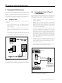
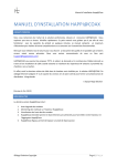
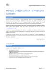
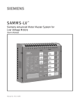
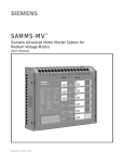
Isolated Multi-Drop™Converter
Operator’s Manual
LOGO
Po rt 1
Tx Rx
Po rt 2
Tx Rx
Po rt 3
Tx Rx
RS485
Isolated Multi-Dro
Po rt 4
Tx Rx
RS485
RS485
RS485
Manual No. SG-6048-01
p™
The use of unauthorized parts in the repair of the equipment or tampering by unqualified personnel will result in dangerous conditions
which may cause severe personal injury or equipment damage.
Follow all safety instructions contained herein.
IMPORTANT
The information contained herein is general in nature and not
intended for specific application purposes. It does not relieve the
user of responsibility to use sound practices in application, installation, operation, and maintenence of the equipment purchased. Siemens reserves the right to make changes at any time without notice
or obligations. Should a conflict arise between the general information contained in this publication and the contents of drawings or
supplementary material or both, the latter shall take precedence.
QUALIFIED PERSON
For the purposes of this manual a qualified person is one who is
familiar with the installation, construction, or operation of the equipment and the hazards involved.
SUMMARY
These instructions do not purport to cover all details or variations in equipment, nor to provide for every possible contingency to
be met in connection with installation, operation, or maintenence. Should further information be desired or should particular
problems arise which are not covered sufficiently for the purchaser’s purposes, the matter should be referred to the local sales
office.
The contents of the instruction manual shall not become part of or modify any prior or existing aggreement, commitment or
relationship. The sales contract contains the entire obligation of Siemens Energy & Automation, Inc. The warranty contained in
the contract between parties is the sole warranty of Siemens Energy & Automation, Inc. Any statements contained herein do
not create new warranties or modify the existing warranty.
Contents
1
Introduction ..................................1
1.1
1.2
Product Summary......................................1
How to Use This Manual ...........................1
2
Setting Up the Converter.............2
2.1
2.2
2.3
2.4
2.5
Overview....................................................2
RS-485 Communications Ports.................2
RS-232 Communications Port ..................2
Power Module ...........................................2
Configuration Switches .............................2
2.5.1 TX CONTROL Switches ......................2
2.5.2 Operating in Manual Mode .................3
2.5.3 Operating in Automatic Mode.............3
3
Installing the Converter ...............4
3.1
3.2
3.3
3.4
3.5
Getting Ready............................................4
Preparing the RS-485 Cable .....................4
Connecting Directly to a PC ......................5
Connecting with Short-Haul Modems.......6
Connecting with Dial-Up Modems ............7
4
Testing ACCESS Devices ............8
4.1
4.2
4.3
4.4
Prepare Cable............................................8
Testing Static Trip III in Type RL
Circuit Breaker...........................................8
Testing Static Trip III on Desktop...............9
Testing SAMMS on Desktop .....................9
5
Troubleshooting .........................11
Appendix A: Block Diagram
Appendix B: Mounting Dimensions
ACCESS, Isolated Multi-Drop, Power Monitor PC, SEAbus, SIEServe, Static Trip III , SAMMS and WinPM are trademarks of
Siemens Energy & Automation, Inc. Windows is a trademark and Microsoft is a registered trademark of Microsoft Corporation.
Siemens Energy & Automation, Inc.
1 Introduction
1 Introduction
1.1
Product Summary
The Siemens Isolated Multi-DropTM converter is an
electronic device that lets you connect your DOS-based PC
to the Siemens SEAbusTM communications network for
ACCESSTM devices on your power distribution system. (You
can also use the converter to connect other RS-485
devices, such as Multilin 169+ and 269+ relays, to your PC.)
The Isolated Multi-Drop converts the RS-232 signal from
your PC to an RS-485 signal used in an industrial network
such as the ACCESS electrical distribution communications
system. With your PC connected to the network in this
manner, you can run Siemens WinPMTM communications
and supervisory software, or Siemens SIEServeTM display
and monitoring software for MicrosoftTM WindowsTM, to
communicate with every ACCESS device on your system.
The Isolated Multi-Drop converter has four RS-485 ports
that can support 32 devices each, for a total of 128 devices
on each of your PC’s serial ports. If you are using SIEServe
software, you can run one copy of the program for each
serial port on your computer.
1.2
How to Use This Manual
This manual is intended to provide you with all the
information you need to install and troubleshoot the Isolated
Multi-Drop converter on your ACCESS system. It tells you
how to connect your PC and the rest of the ACCESS
system directly, and how to connect over longer distances
using modems. For help in finding the information you need
in this manual, refer to Table 1.1.
Table 1.1 Manual Help
If you need more info about:
Refer to:
the features of the converter
Section 2
how to install and set up the converter
Section 3
how to connect Static Trip units and
SAMMS devices for testing
Section 3
troubleshooting
Section 4
mounting dimensions
Appendix B
The Isolated Multi-Drop converter also protects the PC from
field-device potentials by providing opto-isolators between
the RS-232 and RS-485 interfaces. To isolate the PC
further,
the converter is equipped with high-energy surge
suppression that meets or exceeds ANSI C62.41 (IEEE 587)
standards. The converter also incorporates isolated DC/DC
converters that provide electrical isolation between the PC
and the RS-485 loop.
The Isolated Multi-Drop converter is designed with features
that enable you to set it up and install it easily to meet the
specific requirements of your operation.
Siemens Energy & Automation, Inc.
1
2 Setting Up the Converter
2 Setting Up the Converter
2.3
RS-232 Communications Port
Before connecting the converter to your system, understand
the connectors, LEDs and switches. This section describes
each of the following features according to their functions:
The converter is equipped with one RS-232
communications port located on the rear panel, as
illustrated in Figure 2.4. This port lets you connect the
converter to a PC for desktop operation, or to a short-haul
or dial-up modem for remote operation.
•
four RS-485 communications ports
2.4
•
one RS-232 communications port
•
power module
•
three configuration switches for communications
•
manual and automatic operating modes
The interface of the converter’s power module is located on
the rear panel, as illustrated in Figure 2.4. The power
module includes an ON/OFF switch, an indicating power
(PWR) LED, a 120 VAC power input, and a 15 VDC power
output. The 15 VDC output is used to provide power to
Static Trip IIITM trip units and SAMMSTM motor control and
protection relays during testing. The filtered input next to the
power switch is for providing line power to the converter.
The power switch turns the converter on and off, and the
PWR LED illuminates when the converter is turned on.
2.1
Overview
2.2
RS-485 Communications Ports
The Isolated Multi-Drop converter is equipped with four
RS-485 ports located on the converter’s front panel,
as illustrated in Figure 2.1
RS-485 receptacles
RS485
+
_
RS485
+
_
RS485
+
_
RS485
+
_
2.5
Each port allows you to connect as many as 32 field devices
on a single RS-485 communications cable; however, your
application software may limit the number of devices your
system can accommodate. Each port has Data(+) and
Data(-) terminals and a ground terminal for the cable shield.
For diagnostics, each port is equipped with a yellow
transmit (Tx) LED and a green receive (Rx) LED, located on
top of the device. The Tx LEDs blink during the transmission
of data, which occurs on all ports simultaneously; only one
Rx LED blinks when data is received. The LEDs are
illustrated in Figure 2.2
Figure 2.2 Communications LEDs on the Top Panel
2
Configuration Switches
On the rear panel are the converter’s three configuration
switches, collectively labeled “TX CONTROL”. Set these
switches before operating the converter. Refer to Figure 2.4
for the location of these switches. The two switches, labeled
DCD/RTS and MAN/AUTO, and one thumbwheel switch,
labeled BAUD are described below. This section describes
the uses of each configuration switch in more detail.
2.5.1
Figure 2.1 Connectors on Front Panel
Power Module
TX CONTROL Switches
The MAN/AUTO switch places the Isolated Multi-Drop
converter in either manual or automatic operating mode,
both of which are described below. Your application
software determines which mode you should use.
The DCD/RTS switch is set according to the method of data
transmission for your configuration. Set the switch to DCD
for the Data Carrier Detect (DCD) circuit (pin 8, RS-232
cable) to send a message to the PC when a proper carrier
signal is received. Set the switch to RTS for the Request To
Send (RTS) circuit (pin 4, RS-232 cable) to send a message
to the converter requesting permission to send data on the
Tx Data circuit (pin 2, RS-232 cable). Figure 2.3 shows the
switches set to DCD and AUTO.
Figure 2.3 Tx Control Switches
Siemens Energy & Automation, Inc.
2 Setting Up the Converter
.
Figure 2.4 Rear Panel
The BAUD thumbwheel switch selects the data rate for
communications. Set the data rate to be consistent with the
data rate for your system’s SEAbus communications
network.
Table 2.1 Tx Control Baud Settings
Dial Number
Data Rate (bps)
1
1200
2
2400
3
4800
4
>9600
2.5.2
Operating in Manual Mode
Set the converter to manual mode since most Siemens
application software uses RTS to enable the Isolated MultiDrop converter’s transmitter. (If your software does not use
RTS to enable the transmitter, refer to your user’s manual for
more information.) When the Isolated Multi-Drop converter is
connected directly to a PC, the MAN/AUTO switch must be
set to MAN and the DCD/RTS switch must be set to RTS.
When the Isolated Multi-Drop converter is installed at a
remote location using short-haul modems, the MAN/AUTO
switch must be set to MAN and the DCD/RTS switch must
be set to DCD. Short-haul modems typically pass RTS
through on the DCD pin at the remote modem.
2.5.3
Operating in Automatic Mode
Set the converter to automatic mode if you use application
software that does not support hardware handshaking (that
is, DCD/RTS) or that communicates to a remote location via
a dial-up modem on a nondedicated telephone line. With
the MAN/AUTO switch set to AUTO, the converter’s
transmitter is enabled by the data signal transmitted from
the computer. To set up the Isolated Multi-Drop converter
for Automatic mode, the MAN/AUTO switch is set to AUTO,
and the BAUD thumbwheel switch is set to match the data
rate on the communications network.
Siemens Energy & Automation, Inc.
3
3 Installing the Converter
3 Installing the Converter
3.1
Getting Ready
This section explains how to install the Isolated Multi-Drop
converter for your operation. You can install the converter
either directly to a PC or remotely within switchgear using
short-haul or dial-up modems. This section also tells you
how to connect Static Trip III trip units and SAMMS devices
to the converter’s power module, enabling you to test these
devices in the field.
Before attempting to install the converter, check to see that
you have the following parts in addition to the converter:
•
a power cord
•
a two-terminal connector
•
four RS-485, three-terminal connectors
Note: Make sure that each device attached to the
communications network through the converter
has a unique address to prevent communications
collisions. Device addressing is a process
independent of installation. For instructions on how
to program the address of a specific device, see
the instruction manual for that device or refer to the
latest revision of the ACCESS System Installation
Guide. (Manual No. SG-6028).
3.2
6.
Insert the connector into one of the RS-485 ports
located on the front panel of the Isolated Multi-Drop
converter.
+
Preparing the RS-485 Cable
-
The converter comes with four connectors to connect your
system’s RS-485 cable to the converter. Use these
connectors to connect as many as four cable runs to the
converter’s four RS-485 ports. To install connectors on
RS-485 cable, follow these instructions and refer to
Figure 3.1:
1.
Strip the insulation off the black, white, and shield wires
at both ends of the RS-485 communications cable,
exposing approximately 0.5inch of metal wire on each.
2.
Loosen the three screws in the RS-485 connector.
3.
Insert the black wire from both ends of the
communications cable into the Data(+) slot on the
connector, and tighten the screw to secure the wires.
4.
Insert the white wire from both ends of the
communications cable into the Data(-) slot on the
connector, and tighten the screw to secure the wires.
5.
Insert the shield wire from only one end of the
communications cable into the center slot on the
connector, and tighten the screw to secure the wire.
4
BLK
WHT
Figure 3.1 Communications Cable Connection
Siemens Energy & Automation, Inc.
3 Installing the Converter
3.3
Connecting Directly to a PC
To connect the Isolated Multi-Drop converter directly to a
PC, you need an RS-232 serial cable of not more than 50
feet in length. Make sure the cable is a DCE-DTE cable, not
a null modem cable. The following table lists the minimum
set of required signals and the pin assignments for DB-25 to
DB-25 and DB-9 to DB-25 cable connectors:
4.
Insert the RS-485 connector(s) into the port(s) on the
front of the converter. (Refer to section 3.1 for
instructions on installing a connector on the RS-485
cable.)
5.
Connect the supplied power cord to the 120 VAC
connector on the converter, and plug the other end into
any 120 VAC grounded power source.
6.
Turn the converter’s power switch on, and verify that
the PWR LED is lit. (Refer to Section 5
“Troubleshooting” if the PWR LED is not lit.)
7.
Start your software.
Table 3.1 RS-232 Pin Assignments
Pin Number
on Connector
Signal Name
2
TxD
3
RxD
4
RTS
7
GND
8
DCD
To connect the converter to a PC, follow these steps while
refering to Figure 3.3 below:
1.
Connect the plug end of an RS-232 serial cable to
the RS-232 port on the Isolated Multi-Drop converter.
2.
Connect the socket end of the serial cable to an
RS-232 port on your computer.
3.
If you are using application software that requires direct
DCD/RTS control, set the DCD/RTS switch to RTS and
the MAN/AUTO switch to MAN. If you are using
application software that does not require the direct
DCD/RTS control, set the MAN/AUTO switch to AUTO,
and use the BAUD thumbwheel to set the data rate to
match that of the application software and the
ACCESS devices on the network. (In automatic mode,
the converter ignores the setting of the DCD/RTS
switch.)
+
22 AWG Shielded
Twisted-Pair Cable
+
Port 4
Device
#1
4000 Ft. Maximum
SHLD
-
+
Port 3
-
SHLD
-
RS-485
Bus
+
-
Device
#n
+
RS-232 Cable
Port 2
Up to 32 devices
SHLD
-
50 Ft. Maximum
+
PC
with
Supervisory
Software
Port 1
SHLD
-
To Other
RS-485
Devices
Isolated Multi-Drop
Converter
Figure 3.2 Connecting the Converter Directly to a PC
Siemens Energy & Automation, Inc.
5
3 Installing the Converter
3.4
Connecting with Short-Haul
Modems
If the distance between your PC and Isolated Multi-Drop
converter is greater than 50 feet but less than 3.5 miles, you
can connect them using short-haul modems and regular
telephone cable. To install the Isolated Multi-Drop converter
using short-haul modems, you need these items:
•
two short-haul modems
•
telephone cable that does not exceed 3.5 miles in
length
•
one Isolated Multi-Drop converter mounting kit (if you
want to mount the converter in a switchgear panel)
•
one or two RS-232 serial cables
for either side of the modem connection
3.
Insert the RS-485 connector(s) into the port(s) on the
front of the converter. (Refer to section 3.1 for
instructions on installing a connector on the RS-485
cable.)
4.
Connect the supplied power cord to the 120 VAC
connection on the converter, and plug the other end
into any 120 VAC grounded power source.
5.
Turn the converter’s power switch on, and verify that
the PWR LED is lit. (Refer to Section 5
“Troubleshooting” if the PWR LED is not lit.)
6.
Start your software.
For the RS-232 cables, use DCE-DTE cable with the pin
assignments given in Table 3.1. For mounting to a
switchgear panel, mount the converter before wiring. (Refer
to Appendix B for mounting dimensions.) Then follow these
steps, referring to Figure 3.3.
1.
Connect short-haul modems to the RS-232 port on the
converter and to the RS-232 port on the PC. Plug them
directly into the ports or use the RS-232 serial cables.
(If you need help in connecting the modems and setting
their switches, refer to the modem’s manual.)
2.
If you’re using application software that requires direct
DCD/RTS control, set the DCD/RTS switch to DCD
and the MAN/AUTO switch to MAN. If you are using
application software that does not require direct DCD/
RTS control, set the MAN/AUTO switch to AUTO, and
use the BAUD thumbwheel to set the data rate to
match that of the application software and the
ACCESS devices on the network. (In Automatic mode,
the converter ignores the setting of the DCD/RTS
switch.)
+
22 AWG Shielded
Twisted-Pair Cable
+
Port 4
Two Twisted-Pair Cables
3.5 Miles Maximum
Device
#1
4000 Ft. Maximum
SHLD
-
+
Port 3
-
SHLD
-
RS-485
Bus
+
-
Device
#n
+
RS-232 Cable
50 Ft. Maximum
PC
RS-232 Cable
ShortHaul
Modem
with
Supervisory
Software
ShortHaul
Modem
Port 2
Up to 32 devices
SHLD
-
50 Ft. Maximum
+
Port 1
SHLD
-
To Other
RS-485
Devices
Isolated Multi-Drop
Converter
Figure 3.3 Connecting With Short-Haul Modems
6
Siemens Energy & Automation, Inc.
3 Installing the Converter
3.5
Connecting with Dial-Up Modems
If the distance between your PC and Isolated Multi-Drop
converter is greater than 3.5 miles, you can connect them
using dial-up modems. To install the Isolated Multi-Drop
converter using dial-up modems, you need these items:
•
two dial-up modems
•
one RS-232 serial cable no more than 50 feet in length
(unless your PC’s modem is directly installed in the
computer)
•
one null modem cable no more than 50 feet in length
•
a telephone line for each modem
•
one Isolated Multi-Drop converter mounting kit (if you
want to mount the converter to the switchgear panel)
1
2
3
4
5
6
7
8
Pins 2 and 3
Transposed
*
20
Connect one dial-up modem to your PC; use RS-232
serial cable unless your modem is installed directly in
the computer. (If you need help in connecting the
modems and setting their switches, refer to the
modem’s manual.)
2.
Using a null modem cable, connect one dial-up modem
to the RS-232 port on the converter according to
Figure 3.5.
3.
Set the MAN/AUTO switch to AUTO, and use the
BAUD thumbwheel to set the data rate to match that of
the application software and the ACCESS devices on
the network. (In Automatic mode, the converter ignores
the setting of the DCD/RTS switch.)
Not required
*with
converter
20
To
Isolated
Multi-Drop
Converter
To
Modem
If you are mounting the Isolated Multi-Drop converter to a
switchgear panel, do that first. (Refer to Appendix B for
mounting dimensions.)
Follow these steps, while referring to Figure 3.4.
1.
*
1
2
3
4
5
6
7
8
Figure 3.5 Pin Assignments for Null Modem Cable
4.
Insert the RS-485 connector(s) into the port(s) on the
front of the converter. (Refer to section 3.1 for
instructions on installing the connector on the RS-485
cable.)
5.
Plug one end of the converter’s power cord into the
120 VAC connection on the converter, and plug the
other end into any 120 VAC grounded power source.
6.
Turn the converter’s power switch on, and verify that
the PWR LED is lit. (Refer to Section 5
“Troubleshooting” if the PWR LED is not lit.)
7.
Start your software.
+
22 AWG Shielded
Twisted-Pair Cable
IMPORTANT
Use a null modem cable
between the Isolated
Multi-Drop Converter
and the modem.
+
Port 4
4000 Ft. Maximum
SHLD
-
RS-485
Bus
+
-
Modem
Modem
RS-232 Cable
50 Ft. Maximum
PC
with
Supervisory
Software
Device
#1
SHLD
-
+
Port 3
-
Device
#n
+
Port 2
Up to 32 devices
SHLD
-
Null Modem Cable
50 Ft. Maximum
+
Port 1
SHLD
-
To Other
RS-485
Devices
Isolated Multi-Drop
Converter
Figure 3.4 Connecting the Converter with Dial-Up Modems
Siemens Energy & Automation, Inc.
7
4 Testing ACCESS Devices
4 Testing ACCESS Devices
You can use the Isolated Multi-Drop converter’s 15 VDC
power output to provide DC power for testing Static Trip III
trip units or SAMMS devices. According to the steps in this
section, first prepare a cable for connecting the devices to
the converter. Then follow the appropriate procedure for the
specific device(s) you want to connect to the converter.
4.2
4.1
1.
Plug the connector of the two-conductor cable into the
15 VDC output port.
2.
Making sure to observe the polarity of the cable,
connect the other end to terminals 2 and 3 on the
terminal block for cubicle disconnect. (This terminal
block is located on the inside left panel of the Type RL
circuit breaker compartment.)
3.
Connect an RS-485 cable between the terminal block
in the circuit breaker and the converter. (You may need
to prepare a length of communications cable as
described in section 3.1 above.) Plug the cable’s threeterminal connector into an RS-485 port on the front of
the converter. Connect the black wire from the other
end of the cable to Data(+) (terminal 4) on the terminal
block, and connect the white wire to Data(-) (terminal 5)
on the terminal block.
4.
Plug one end of the converter’s power cord into the
120 VAC connection on the converter, and plug the
other end into any 120 VAC grounded power source.
5.
Turn the power switch on.
6.
Using testing software supplied by Siemens, verify that
the attached trip unit communicates properly.
Prepare Cable
To prepare the cable, follow these steps while referring to
Figure 4.1.
1.
Select a two-conductor cable of sufficient length to
reach between the converter and the device(s) you
want to connect.
2.
Strip the insulation from both wires at both ends of the
cable, exposing approximately 0.5 inch of metal wire on
each.
3.
Loosen the screws in the two-terminal connector that
comes with the converter. Insert one wire into each slot
on the connector, making sure to take note of polarity.
+
-
Testing Static Trip III in Type RL
Circuit Breaker
If you are testing a Static Trip III trip unit in a Type RL circuit
breaker, follow these steps to connect the trip unit to the
converter for 15 VDC power, while referring to Figure 4.2:
Isolated Multi-Drop
rear panel
BLK
15VDC
+
WHT
-
Two-wire cable
OUT
+/- 15 VDC
BLK
Figure 4.1 Two-Terminal Connector for Test Connection
RS-485 cable
WHT
Data (+)
Data (-)
RS485
Use this cable to connect devices to the converter
according to the procedures in the remainder of this section.
RS485
+
_
Terminal block for
cubicle disconnect
on inside-left panel of
Type RL circuit breaker
compartment
_
+
RS485
+
_
RS485
+
_
RS485
+
_
front panel
Figure 4.2 Test Connection for Static Trip III
in Type RL Circuit Breaker
8
Siemens Energy & Automation, Inc.
4 Testing ACCESS Devices
4.3
Testing Static Trip III on Desktop
If you are testing a Static Trip III trip unit on a desktop, follow
these steps to connect the trip unit to the converter for
15 VDC power, while referring to Figure 4.3:
1.
Plug the connector of the two-conductor cable into the
15 VDC output port.
2.
Making sure to observe the polarity of the cable,
connect the other end to terminals 2 and 3 on the
10-pin connector supplied with the Static Trip III.
3.
Connect an RS-485 cable between the 10-pin
connector and the converter. (You may need to prepare
a length of RS-485 cable as described in section 3.1
above.) Plug the cable’s three-terminal connector into
an RS-485 port on the front of the converter. Connect
the black wire from the other end of the cable to
Data(+) (terminal 4) on the 10-pin connector,
and connect the white wire to Data(-) (terminal 5)
on the 10-pin connector.
4.
Plug the 10-pin connector into the 10-pin connector
port located on the back panel of the Static Trip III.
5.
Plug one end of the converter’s power cord into the
120 VAC connection on the converter, and plug the
other end into any 120 VAC grounded power source.
6.
Turn the power switch on.
7.
Using testing software supplied by Siemens, verify that
the attached trip unit communicates properly.
4.4
If you are testing a SAMMS device on a desktop, follow
these steps to connect the device to the converter, while
referring to Figure 4.4 on the next page and to the SAMMSLV User’s Manual (Manual No. MC-3298) or SAMMS-MV
User’s Manual (Manual No. MVC-9108):
1.
Prepare 2 two-conductor cables by connecting them to
one two-terminal connector, as described at the
beginning of this section and illustrated in Figure 4.4.
2.
Plug the connector of the two-conductor cables into
the 15 VDC output port.
3.
Making sure to observe the polarity, connect the other
end of one of the two-conductor cables to terminals
5 and 6 of the terminal block on top of the SAMMS.
4.
Again making sure to observe polarity, connect the
other end of the second two-conductor cable to the
PWR (+) and PWR (-) terminals on the five-terminal
connector supplied with the SAMMS Communication
Module CM-1.
5.
Connect an RS-485 cable between the SAMMS fiveterminal connector and the converter. (You may need to
prepare a length of RS-485 cable; see section 3.1.)
6.
Plug the cable’s three-terminal connector into an
RS-485 port on the front of the converter. Connect the
black wire from the other end of the cable to the (+)
terminal on the five-terminal connector, and connect
the white wire to the (-) terminal on the connector.
7.
Plug the five-terminal connector into the SAMMS
Communication Module CM-1.
8.
Connect the CM-1 to the SAMMS device using the
supplied ribbon cable as illustrated in Figures 12 and
13.
9.
Plug one end of the converter’s power cord into the
120 VAC connection on the converter, and plug the
other end into any 120 VAC grounded power source.
Isolated Multi-Drop
rear panel
15VDC
-
+
Two-wire cable
OUT
BLK
RS-485 cable
RS485
_
+
RS485
+
_
RS485
+
_
RS485
+
_
RS485
+
_
front panel
WHT
1
2
3
4
5
6
7
8
9
10
Testing SAMMS on Desktop
+/- 15VDC
10. Turn the power switch on.
Data (+)
Data (-)
11. Using testing software supplied by Siemens, verify that
the attached SAMMS device communicates properly.
10-pin connector
on Static Trip III
Figure 4.3 Connecting a Static Trip III for Desktop Testing
Siemens Energy & Automation, Inc.
9
4 Testing ACCESS Devices
Pins 5 and 6
Isolated Multi-Drop
1
2
3
4
5
6
7
8
9
10
11
12
13
14
15
16
rear panel
15VDC
+
SAMMS
device
Two-wire cable
-
OUT
RS485
_
RS485
+
_
Ribbon cable
RS485
+
_
RS-485 cable
CM-1
RS485
+
_
front panel
1 2 3 4
RS485
+
Two-wire cable
_
+
Figure 4.4 Connecting SAMMS Device for Testing
10
Siemens Energy & Automation, Inc.
5 Troubleshooting
5 Troubleshooting
If you experience communications errors and suspect the
Isolated Multi-Drop converter is at fault, perform the actions
listed below. Before performing these tests:
1.
Verify that your application software is properly set up.
2.
Verify that the cables between the components are
connected correctly according to the installation
instructions.
If transmission through the Isolated Multi-Drop converter
fails (one or more of the Tx LEDs fails to blink), perform the
following checks in the order given:
1.
If some (but not all four) of the Tx LEDs blink
simultaneously, the Isolated Multi-Drop converter is
faulty and should be replaced.
2.
If none of the Tx LEDs flash, perform the following
steps in order:
a.
Check the power connection and verify that the
PWR LED is lit.
b.
Verify that the Tx Control switches are set
according to the specifications of your application
software.
c.
Verify that the PC’s serial port is working properly. If
it is, try replacing the cable to the converter.
If data errors occur or if there is no response from the field
devices (Rx LED fails to flash), perform the following checks
in the order given:
1.
If correct data is transmitted from a field device but
communication errors occur or no Rx LED flashes,
check the following:
a.
Verify that the field device is receiving power.
b.
Verify that the cable from the converter to the field
device is correct.
c.
Verify that the device’s communications address
matches the address assigned by the software for
that device.
d.
Verify that the device’s data rate matches that of
the software.
2.
Verify proper operation of the attached field device’s
RS-485 communication interface. For more detailed
troubleshooting information on field devices, refer to
troubleshooting guidelines in Installing the ACCESS
System (Manual No. SG-6028).
3.
Verify that the Data(+) and Data(-) port of each device is
connected to the corresponding ports of the converter.
Siemens Energy & Automation, Inc.
11
5 Troubleshooting
NOTES:
12
Siemens Energy & Automation, Inc.
Appendices
Appendix A: Block Diagram
The illustration below is a block diagram showing how the Isolated Multi-Drop converter operates.
The diagram identifies the internal components that make up the converter.
Galvanically Isolated
RS-485 Logic
RXD
TXD
RS-232
Connector
RTS
RS-485
Transceiver (4)
RS-232
Transceiver
25-pin D
Connector
+
Tx Enable
SHIELD
Tx Enable
SHIELD
3
-
RS-485
Port 1
2
+
4
-
RS-485
Port 2
8
DCD
Signal 7
Ground
+
SHIELD
Tx Enable
-
+
SHIELD
Tx Enable
Baud
Switch
Tx
Enable
Logic
-
RS-485
Port 3
RS-485
Port 4
Earth Ground
RTS/DCD
AUTO/MAN
RTS
MAN
DCD
AUTO
Opto-isolators
for each data
channel
5V
Power Supply
120 VAC/
125 VDC
Source
5V
15V
Isolated
Supply
DC
DC
+
-
External 15V DC output
Earth Ground
Figure A.1. Block Diagram
Siemens Energy & Automation, Inc.
13
Appendices
14
Siemens Energy & Automation, Inc
Appendices
Appendix B: Mounting Dimensions
The illustration below shows the mounting dimensions for the Isolated Multi-Drop converter.
Use these dimensions to muont the converter to a switchgear panel or to some other location.
For more information on installation, refer to section 3, Installing the Converter.
8.4
Figure B.1. Mounting Dimensions
Siemens Energy & Automation, Inc.
15
Appendices
16
Siemens Energy & Automation, Inc
Siemens Energy &
Automation, Inc.
Switchgear and Motor Control
Business
P.O. Box 29503
Raleigh, NC 27626-0503
Manual No. SG-6048-01 (Replaces -00) 1M 0595FP Printed in U.S.A.
© 1992-1995 Siemens Energy & Automation, Inc.
SIEMENS is a registered trademark of Siemens AG