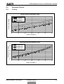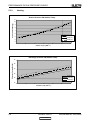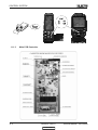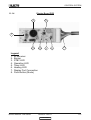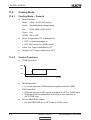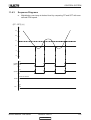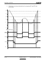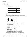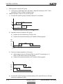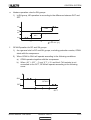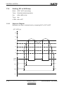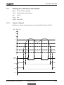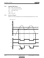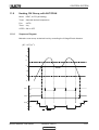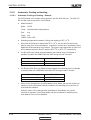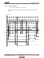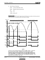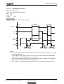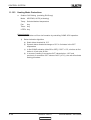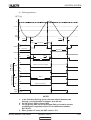
1
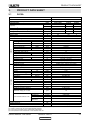
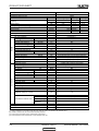
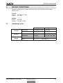
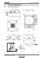
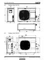
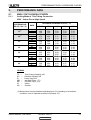
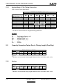
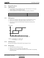
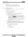
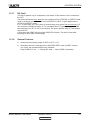
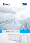
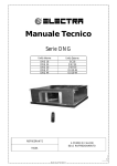
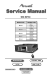
KN Cassette R410A Series
Indoor Units
Outdoor Units
KN 24 RC
OU7-24 RC
KN 24 RC 3PH
OU7-24T RC
REFRIGERANT
R410A
COOLING ONLY
HEAT PUMP
SEPTEMBER - 2005
CONTENT
INTRODUCTION
1.
INTRODUCTION
1.1
General
The cassette (900X900) split celling mounted range comprise the ST (cooling only) and
RC (heat pump) models, as follows:
1.2
•
Cooling Only
KN24ST, KN30ST , 1PH & 3PH units
•
Heat Pump
KN24RC, KN30RC, 1PH & 3PH units
Main Features
The (900X900) Cassette series benefits from the most advanced technological
innovations, namely:
1.3
•
R410A units
•
Microprocessor control.
•
Indoor spacial centrifugal fan for low noise opration
•
High COP.
•
Easy access to interconnecting tubing and wiring connections,
•
Integral condensate water pump.
•
Automatic treated air sweep.
•
Easy installation and service.
Indoor Unit
The indoor unit is celling mounted, and can be easily fitted to many types of residential
and commercials applications.
It includes:
1.4
•
Square bended coil with hydrophilic aluminum fins.
•
A large diameter centrifugal fan
•
Motorized flaps
•
Advanced electronic control box assembly.
Filtration
The Cassette series presents with easily accessible, and re-usable pre-filters (mesh)
1.5
Control
The microprocessor indoor controller, and an infrared remote control, supplied as
standard, provide complete operating function and programming. For further details
please refer to the Operation Manual, Appendix A.
Service Manual - KN Series
Revision Y05-01
CONTENT
1-1
INTRODUCTION
1.6
Outdoor Unit
The Cassette outdoor units can be installed as floor or wall mounted units by using a
wall supporting bracket. The metal sheets are protected by anti- corrosion paint work
allowing long life resistance. All outdoor units are pre-charged. For further information
please refer to the Product Data Sheet, Chapter 2.
It includes :
1.7
•
A Rotary Compressor mounted in a soundproofed compartment
•
Axial fan.
•
Outdoor coil with hydrophilic louver fins for RC units.
•
Outlet air fan grill.
•
Service valves” flare” type connection.
•
Interconnecting wiring terminal block.
•
Integra Electrical phase protector (on 3PH models).
•
Advanced TYPHOON PCB
Tubing Connections
Flare type interconnecting tubing to be produced on site.
For further details please refer to the Installation Manual, Appendix A.
1.8
Accessories
ASK (All Season Kit):
For low ambient working conditions in cooling, an ASK can be installed.This kit allows
cooling operation down to outdoor temp of -10 ºC by gradually controlling the outdoor
fan speed motor.
RCW Wall Mounted Remote Control
The RCW1/ RCW2 remote control is a wall mounted remote controler, for multi indoor
unit aplications and functioning
For further details please refer to Optional Accessories, Chapter 18.
1.9
Inbox Documentation
Each unit is supplied with its own installation and operation manuals.
1-2
Revision Y05-01
CONTENT
Service Manual - KN Series
PRODUCT DATA SHEET
2.
PRODUCT DATA SHEET
2.1
R410A
Model Indoor Unit
Model Outdoor Unit
Installation Method of Pipe
Characteristics
Capacity
(1)
INDOOR
OUTDOOR
Operation control type
Heating elements
Others
(1)
(2)
(3)
(4)
g/m
25
In.(mm)
In.(mm)
m.
3/8"(9.53)
5/8"(15.88)
Max.30
m.
Max.15
V/Ph/Hz
A
A
A
H/M/L
H/M/L
Min-Max
H/M/L
H/M/L
RPM
m3/hr
Pa
dB(A)
dB(A)
l/hr
mm
mm
kg
mm
kg
units
units
WxHxD
WxHxD
H/L
H/L
H/L
H/L
WxHxD
RPM
m3/hr
dB(A)
dB(A)
mm
kg
mm
kg
Units
units
WxHxD
Additional charge per 1 meter
Connections between units
kg/m
Units
Btu/hr
kW
kW
W/W
(1)
Power input
(1)
EER (Cooling) or COP(Heating)
Energy efficiency class
Power supply
Rated current
Starting current
Circuit breaker rating
Fan type & quantity
Fan speeds
(2)
Air flow
External static pressure
(3)
Sound power level
(4)
Sound pressure level
Moisture removal
Condensate drain tube I.D
Dimensions
Weight
Package dimensions
Packaged weight
Units per pallet
Stacking height
Refrigerant control
Compressor type, model
Fan type & quantity
Fan speeds
Air flow
Sound power level
(4)
Sound pressure level
Dimensions
Weight
Package dimensions
Packaged weight
Units per pallet
Stacking height
Refrigerant type
Refrigerant chargless distance
KN-24
OU7-24
Flared
Cooling Only
Cooling
Heating
23100
23100
24150
6.77
6.77
7.08
2.25
2.25
2.33
3.01
3.01
3.04
B
D
B
220-240V/Single/50Hz
9.6
9.6
9
63
20
Centrifugal x 1
570/510/460
910/800/690
N/A
54/50/48
44/41/38
2.5
32
840x230x840 (Unit) / 950x46x950 (Frame)
36 (unit) / 6 (Frame)
1011x333x931 (Unit) / 1013x145x1013(Frame)
40 (unit) / 7 (Frame)
5(Unit) / 15(Frame)
5 Levels (unit) / 15 Levels (Frame)
Capillary tube restrictor for heating)
Rotary, Mitsubishi NN27VBAMT
Propeller(direct) x 1
850
3100
67
58
900x680x340
78
985x730x406
82
6
2 Levels
R410A
2.16kg/12.5m
Liquid line
Suction line
Max .tubing length
Max .height
difference
Remote control
kW
ASK – Factory Option
Rating conditions in accordance with ISO 5151 and ISO 13253 (for ducted units) and EN 14511.
Airflow in ducted units; at nominal external static pressure.
Sound power in ducted units is measured at air discharge.
Sound pressure level measured at 1 meter distance from unit.
Service Manual - KN Series
Revision Y05-01
CONTENT
2-1
PRODUCT DATA SHEET
Model Indoor Unit
Model Outdoor Unit
Installation Method of Pipe
Characteristics
Capacity
(1)
INDOOR
OUTDOOR
Operation control type
Heating elements
Others
(1)
(2)
(3)
(4)
g/m
25
In.(mm)
In.(mm)
m.
3/8"(9.53)
5/8"(15.88)
Max.30
m.
Max.15
V/Ph/Hz
A
A
A
H/M/L
H/M/L
Min-Max
H/M/L
H/M/L
RPM
m3/hr
Pa
dB(A)
dB(A)
l/hr
mm
mm
kg
mm
kg
units
units
WxHxD
WxHxD
H/L
H/L
H/L
H/L
WxHxD
RPM
m3/hr
dB(A)
dB(A)
mm
kg
mm
kg
Units
units
WxHxD
Additional charge per 1 meter
Connections between units
kg/m
Units
Btu/hr
kW
kW
W/W
(1)
Power input
(1)
EER (Cooling) or COP(Heating)
Energy efficiency class
Power supply
Rated current
Starting current
Circuit breaker rating
Fan type & quantity
Fan speeds
(2)
Air flow
External static pressure
(3)
Sound power level
(4)
Sound pressure level
Moisture removal
Condensate drain tube I.D
Dimensions
Weight
Package dimensions
Packaged weight
Units per pallet
Stacking height
Refrigerant control
Compressor type, model
Fan type & quantity
Fan speeds
Air flow
Sound power level
(4)
Sound pressure level
Dimensions
Weight
Package dimensions
Packaged weight
Units per pallet
Stacking height
Refrigerant type
Refrigerant chargless distance
KN-24
OU7-24T
Flared
Cooling Only
Cooling
Heating
23100
23100
24150
6.77
6.77
7.08
2.25
2.25
2.33
3.01
3.01
3.04
B
D
B
400V/3PH/50Hz
3 X 7.4
3 X 7.4
3 X 7.6
55
3 X 16
Centrifugal x 1
570/510/460
910/800/690
N/A
54/50/48
44/41/38
2.5
32
840x230x840 (Unit) / 950x46x950 (Frame)
36 (unit) / 6 (Frame)
1011x333x931 (Unit) / 1013x145x1013(Frame)
40 (unit) / 7 (Frame)
5(Unit) / 15(Frame)
5 Levels (unit) / 15 Levels (Frame)
Capillary tube (restrictor for heating)
Rotary, Mitsubishi NN27VDAMT
Propeller(direct) x 1
850
3100
67
58
900x680x340
78
985x730x406
82
6
2 Levels
R410A
2.16kg/12.5m
Liquid line
Suction line
Max .tubing length
Max .height
difference
Remote control
kW
ASK – Factory Option
Rating conditions in accordance with ISO 5151 and ISO 13253 (for ducted units) and EN 14511.
Airflow in ducted units; at nominal external static pressure.
Sound power in ducted units is measured at air discharge.
Sound pressure level measured at 1 meter distance from unit.
2-2
Revision Y05-01
CONTENT
Service Manual - KN Series
RATING CONDITIONS
3.
RATING CONDITIONS
Standard conditions in accordance with ISO 5151, ISO 13253 (for ducted units)
and EN 14511.
Cooling:
Indoor:
27oC DB 19oC WB
Outdoor: 35 oC DB
Heating:
Indoor:
20oC DB
Outdoor: 7oC DB 6oC WB
3.1
Operating Limits
Indoor
Cooling
Heating
Voltage
Service Manual - KN Series
Outdoor
Upper limit
32oC DB 23oC WB
46oC DB
Lower limit
21oC DB 15oC WB
10oC DB
Upper limit
27oC DB
24oC DB 18oC WB
Lower limit
10oC DB
-9oC DB -16oC WB
1PH
198 – 264 V
3PH
360 - 440 V
Revision Y05-01
CONTENT
3-1
OUTLINE DIMENSIONS
4.
OUTLINE DIMENSIONS
4.1
Indoor Unit: KN 24, 30
Necessary room
outlet
inlet
Note: 24/27/30 Series A 260mm
36/45 Series
A 330mm
outlet
Drain side
ground
780 (Hook-location)
840 (Body)
880 (Ceiling hole)
950 (Panel)
Chart 1
Tubing side
780 (Hook-location)
840 (Body)
880 (Ceiling hole)
950 (Panel)
(Unit: mm)
Chart 2
Chart 3
Note: 24/27/30 Series B 240mm
36/45 Series
B 310mm
Hook
Body
Nut
Body
Ceiling
Central hole
Panel
Chart 4
Installation paper
board
H (Ceiling height)
Body M6X12
Ceiling
Body
Chart 7
Chart 5
Service Manual - KN Series
Chart 6
Revision Y05-01
CONTENT
4-1
OUTLINE DIMENSIONS
4.2
Outdoor Unit: OU7-24
4.3
Outdoor Unit: OU8-30
4-2
Revision Y05-01
CONTENT
Service Manual - KN Series
PERFORMANCE DATA & PRESSURE CURVES
5.
PERFORMANCE DATA
5.1
KN24 / OU7-24 R410A 1PH/3PH
5.1.1
Cooling Mode at 7.5m Tubing Connection.
230V : Indoor Fan at High Speed.
ENTERING AIR
DB OD COIL (°C)
15(1)
20(1)
25
30
35
40
46
ENTERING AIR WB/DB ID COIL ( °C)
DATA
TC
SC
PI
TC
SC
PI
TC
SC
PI
TC
SC
PI
TC
SC
PI
TC
SC
PI
TC
SC
PI
15/21
17/24
19/27
21/29
23/32
7.14
4.80
1.60
6.90
4.70
1.73
6.53
4.58
1.87
6.11
4.44
2.02
5.66
4.22
2.18
5.14
3.98
2.35
4.46
3.66
2.57
7.39
5.00
1.60
7.28
4.96
1.74
7.05
4.86
1.88
6.65
4.72
2.05
6.14
4.52
2.21
5.60
4.28
2.39
4.88
3.93
2.60
7.57
5.20
1.60
7.51
5.17
1.74
7.42
5.13
1.90
7.19
5.02
2.07
6.77
4.90
2.25
6.11
4.64
2.43
5.37
4.23
2.66
7.74
5.33
1.60
7.68
5.31
1.75
7.64
5.28
1.91
7.44
5.16
2.08
7.11
5.04
2.27
6.68
4.78
2.46
5.93
4.37
2.70
7.86
5.43
1.61
7.82
5.41
1.76
7.83
5.37
1.92
7.66
5.26
2.10
7.45
5.14
2.28
7.02
4.88
2.48
6.39
4.47
2.73
LEGEND
TC
SC
PI
WB
DB
ID
OD
–
–
–
–
–
–
–
Total Cooling Capacity, kW
Sensible Capacity, kW
Power Input, kW
Wet Bulb Temp., (oC)
Dry Bulb Temp., (oC)
Indoor
Outdoor
(1) Marked area is below standard operating limits. For operating in low ambient
conditions, refer to Optional Accessories (Chapter 15).
Service Manual - KN Series
Revision Y05-01
CONTENT
5-1
PERFORMANCE DATA & PRESSURE CURVES
5.1.2
Heating Mode at 7.5m Tubing Connection.
230V : Indoor Fan at High Speed.
15
ENTERING AIR
WB OU COIL ( °C)
-10
-7
-2
2
6
10
15
20
ENTERING AIR DB ID COIL ( °C)
20
25
TH
PI
TH
PI
TH
PI
4.09
4.40
4.67
5.69
7.29
7.93
8.57
9.03
1.86
1.91
1.93
2.03
2.18
2.30
2.40
2.47
3.93
4.24
4.52
5.45
7.08
7.72
8.35
8.81
1.99
2.02
2.05
2.16
2.33
2.46
2.59
2.68
3.78
4.09
4.36
5.22
6.83
7.50
8.14
8.57
6.34
6.46
6.58
6.94
7.52
7.99
8.35
8.78
* the above chart includes the weighted deicing infleuence.
LEGEND
TH
PI
WB
DB
ID
OU
5.2
–
–
–
–
–
–
Total Heating Capacity, kW
Power Input, kW
Wet Bulb Temp., (oC)
Dry Bulb Temp., (oC)
Indoor
Outdoor
Capacity Correction Factor Due to Tubing Length (One Way)
TOTAL TUBING LENGTH
4m
7.5m
10m
15m
20m
25m
30m
40m
50m
1.01
1
0.98
0.97
0.96
0.95
0.94
---
---
* Minimum recommended tubing length between indoor and outdoor units is 4m.
5.2.1
Heating
TOTAL TUBING LENGTH
4m
7.5m
10m
15m
20m
25m
30m
40m
50m
1.02
1
0.99
0.99
0.98
0.97
0.97
---
---
* Minimum recommended tubing length between indoor and outdoor units is 4m.
5-2
Revision Y05-01
CONTENT
Service Manual - KN Series
PERFORMANCE DATA & PRESSURE CURVES
5.3
Pressure Curves.
5.3.1
Cooling.
Suction Pressure VS.Outdoor Temp
Suction Pressure (Bar[g])
11
21/15(DB/WB
24/17(DB/WB
27/19(DB/WB
29/21(DB/WB
32/23(DB/WB
10
ºC)
ºC)
ºC)
ºC)
ºC)
9
8
7
6
15
20
25
30
35
40
46
40
46
o
Outdoor Temp.(DB C )
Discharge Pressure (Bar[g])
Discharge Pressure VS.Outdoor Temp
40
38
36
34
32
30
28
26
24
22
20
18
16
14
21/15(DB/WB
24/17(DB/WB
27/19(DB/WB
29/21(DB/WB
32/23(DB/WB
15
20
ºC)
ºC)
ºC)
ºC)
ºC)
25
30
35
Outdoor Temp.(DB o C )
Service Manual - KN Series
Revision Y05-01
CONTENT
5-3
PERFORMANCE DATA & PRESSURE CURVES
5.3.2
Heating.
Suction Pressure VS.Outdoor Temp
11
Suction Pressure(Bar[g])
10
9
8
7
6
15 DB (ºC)
5
20 DB (ºC)
4
25 DB (ºC)
3
-10
-5
0
5
10
15
20
Outdoor Temp.( WB o C )
Discharge Pressure VS.Outdoor Temp
Discharge Pressure(Bar[g])
43
38
33
28
25 DB (ºC)
23
20 DB (ºC)
15 DB (ºC)
18
-10
-5
0
5
10
15
20
Outdoor Temp.( WB o C )
5-4
Revision Y05-01
CONTENT
Service Manual - KN Series
CONTROL SYSTEM
11.
CONTROL SYSTEM
11.1
Electronic Control
11.1.1
Introduction
The electronic control information is designed for service applications, and is common
to the following groups of air-conditioners:
x ST/RC group
x SH group
x RH group
11.1.2
-Cooling only / cooling and heating by heat pump.
-Cooling and heating by heat pump and supplementary heater.
-Cooling, heating by heaters only.
Remote Control DIP Switch Settings
SETTING SWITCH STATUS
DEFINITION
SW.
NO. 1
OFF
ON
OFF
ON
--
SW.
NO. 2
OFF
OFF
ON
ON
--
SW.
NO. 3
----OFF
SW.
NO. 4
------
RC-ALL MODES OF OPERATION
STD-COOL, FAN, DRY, ACTIVE
HEAT-COOL, FAN, DRY, ACTIVE
AUTO FAN (AF)
TEMP. DISPLAY IN qC DEGREES
--
--
ON
--
TEMP. DISPLAY IN qF DEGREES
--
--
--
OFF
TIMER & CLOCK 12H AM, PM
--
--
--
ON
TIMER & CLOCK 24H
RC3
RC4
VERTICAL SWING ONLY
HORIZONTAL & VERTICAL
SWING FUNCTIONS
TOGETHER
DISABLE LCD & KEY
ILLUMINATION
ENABLE LCD & KEY
ILLUMINATION
Reset operation - Press the 4 buttons simultaneously: “CLEAR “, “SET”, "HR +”, ”HR -”
for 5 seconds
LEGEND
SW1, SW2 - Selection of RC/ST
SW3 – Selection of Display qC or qF in RC3 or swing function in RC4
SW4 – Selection of Time Display 12H AM/PM or 24H in RC3 or illumination in RC4
OFF = 0
ON = 1
NOTE
After setting the DIP switches perform reset operation.
Service Manual - KN Series
Revision Y05-01
CONTENT
11-1
CONTROL SYSTEM
11.1.3
11-2
Main PCB Controller
Revision Y05-01
CONTENT
Service Manual - KN Series
CONTROL SYSTEM
11.1.4
Display Board PCB
2
8
1
3
4
5
6
7
Legend
1. IR Receiver
2. Buzzer
3. STBY LED
4. Operation LED
5. Timer LED
6. Heating LED
7. Display Port Connection
8. Push Button (Mode)
Service Manual - KN Series
Revision Y05-01
CONTENT
11-3
CONTROL SYSTEM
11.2
Control Function
11.2.1
Abbreviations
AC
- Alternate Current
A/C
ANY
CLOCK
COMP
CPU
CTV
HE
HPC
H/W
ICP
ICT
IF, IFAN
IR
LEVEL1
LEVEL2/3
LEVEL4
Max
Min
min
NA
OCP
OCT
OF, OFAN
OPER
Para.
RAT
RC
R/C
RCT
RH
RT
RV
SB, STBY
sec
Sect
SH
SPT
ST
S/W
TEMP
W/O
- Air-Conditioner
- ON or OFF status
- ON/OFF Operation Input, (dry contact)
- Compressor
- Central Processing Unit
- Compensation Temperature Value
- Heating Element
- High Pressure Control
- Hardware
- Indoor Condensation Pump
- Indoor Coil Temperature (RT2) sensor
- Indoor Fan
- Infrared
- Normal Water Level
- Medium/High Waterlevel
- Overflow Level
- Maximum
- Minimum
- Minute (time)
- Not Applicable
- Outdoor Condensation Pump
- Outdoor Coil Temperature (RT3) sensor
- Outdoor Fan
- Operate
- Paragraph
- Return Air Temperature (RT1) sensor
- Reverse Cycle (Heat Pump)
- Remote Control
- Remote Control Temperature
- Resistance Heater
- Room Temperature (i.e. RCT in IFEEL mode, RAT otherwise)
- Reversing Valve
- Stand-By
- Second (time)
- Section
- Supplementary Heater
- Set Point Temperature
- Standard (Model with Cooling Only)
- Software
- Temperature
- Without
'T
- The difference between SPT and RT.
in Heat Mode:
'T = SPT - RT
in Cool/Dry/Fan Mode: 'T = RT – SPT
11-4
Revision Y05-01
CONTENT
Service Manual - KN Series
CONTROL SYSTEM
11.3
General Functions
11.3.1
COMP Operation
a.
For each Mode including POWER OFF & SB, a Min time delay of 3 min before
COMP restarting, excluding DEICING Mode.
b.
The Min operation time of COMP under different operating conditions is:
Operation Mode
Heat, Cool, HP protection or Auto Modes
Fan, Dry, Overflow, Protection Modes, or Mode Change
11.3.2
Min Operation Time of COMP
3 min.
Ignored
IFAN operation
a.
Min time interval between IFAN speed change in AUTOFAN Mode is 30 sec.
b.
Min time interval between IFAN speed change in H/M/L Mode is 1 sec.
c.
IFAN speed in Heat/Cool AUTOFAN Mode is determined according to the
following chart:
IFAN speed
H
M
L
1
2
3
4
T [oc]
Where in Heat Mode: 'T = SPT - RT
in Cool Mode: 'T = RT- SPT
11.3.3
OFAN Operation
Min time interval between OFAN ON/OFF state changes is 30 sec.
11.3.4
HE Operation
a.
Min Heaters ON or OFF time is 30 sec.
b.
Heaters can never be in operation while IFAN is OFF.
c.
In RH group, HE-1 and HE-2 will be activated only when COMP is not operating,
except in Dry Mode.
Service Manual - KN Series
Revision Y05-01
CONTENT
11-5
CONTROL SYSTEM
11.3.5
11.3.6
Protections
a.
High pressure protection is applicable to all operating modes.
b.
Deicing control is valid in Heat and Auto Heat Modes only.
c.
Defrosting control is valid in Dry, Cool, and Auto Cool Modes.
Thermistors Operation
a.
Return air Temp. is detected by RAT in normal Mode, or by RCT (R/C sensor) in
I-FEEL Mode.
b.
Indoor Coil Temp. is detected by ICT.
c.
Outdoor Coil Temp. is detected by OCT.
d.
Definition of thermistor faults:
e.
11-6
1)
Thermistor is disconnected - the thermistor reading is below – 30OC.
2)
Thermistor is shorted - the thermistor reading is above 75OC.
3)
Thermistor Temp reading doesn’t change a)
This test is performed only once after a unit is switched from OFF/STBY
to operation. At the first occurrence of 10 min continuous COMP
operation, the current ICT are compared with those when the COMP was
switched from OFF to ON 10 min before. If the 'T is less than 3OC, the
thermistor is regarded as defective.
b)
The ICT no-change error can be disabled together by connecting a 4.7k:
resistor (5%) to the ICT connector. These resistors are equivalent to a
thermistor 48+/-1OC.
Cases for disabling ICT thermistor disconnected detection:
1)
The detection of thermistor faults a. and b. above is disabled when Deicer
Protection is started. The detection will be enabled again only after (1) the
deicing is completed, and (2) COMP has been restarted and operated for 30
sec.
2)
When all the following conditions are fulfilled:
a)
4.7k: resistor is connected to the OCT.
b)
IFAN is OFF.
c)
Compressor is ON.
d)
ICT < -30 (disconnected).
Revision Y05-01
CONTENT
Service Manual - KN Series
CONTROL SYSTEM
11.3.7
RV Fault
This test is applied only in compressor units where 4.7k: resistor is not connected to
the OCT.
The test is performed every time the unit is switched from OFF/STBY to OPER in Heat
mode or changes operation mode from COOL/DRY to HEAT or (this applies also in
AUTO COOL/HEAT mode).
If ICT is lower than 35ºC at the time of mode change, then at the first occurrence of 15
min continuous COMP operation, ICT is compared with ICT reading when the COMP
was switched from OFF to ON 15 min before. RV fault is defined when ICT decreases
more than 5ºC.
In this case, the COMP will stop and the SB LED will blink. The fault is reset after
switching to SB or after mode change.
11.3.8
General Features
a.
Allowed (control target) range for RAT is SPT +/-1ºC.
b.
Whenever the unit is changed from COOL/DRY/STBY mode to HEAT mode or
vice versa, the procedures below are followed:
Stop COMP for 3 min o Change RV state o Start COMP if necessary.
Service Manual - KN Series
Revision Y05-01
CONTENT
11-7
CONTROL SYSTEM
11.4
Cooling Mode
11.4.1
Cooling Mode – General
a.
Mode Definition
Mode:
COOL, AUTO (at Cooling)
Temp:
Selected desired temperature.
Fan:
HIGH, MED, LOW, AUTO.
Timer:
Any
I-FEEL: ON or OFF
b.
Room Temperature, RT, is detected by:
x RAT in normal operation, or
x RCT (R/C sensor) in I-FEEL mode.
11.4.2
c.
Indoor Coil Temp is detected by ICT.
d.
Outdoor Coil Temp is detected by OCT.
Control Functions
a.
COMP Operation
COMP
ON
OFF
0
b.
1
RT-SPT
OFAN Operation
x In normal operation OFAN operates together with the COMP.
c.
IFAN Operation
x IFAN will operate in ANY speed regardless the ICT or COMP state.
x IFAN speed will be determined according to user selection or
AUTO-FAN logic
d.
RV and HEATERS outputs
x RV and HEATERS are in OFF state in COOL mode.
11-8
Revision Y05-01
CONTENT
Service Manual - KN Series
CONTROL SYSTEM
11.4.3
Sequence Diagrams
a.
Maintaining room temp at desired level by comparing RT and SPT with user
defined IFAN speed.
(RT - SPT) [oc]
+3
+2
+1
0
-1
-2
ON
COMP
(WVL)
OFF
ON
OFAN
OFF
USER FAN SPEED
IFAN
ON
RV
OFF
Service Manual - KN Series
Revision Y05-01
CONTENT
11-9
CONTROL SYSTEM
b.
Maintaining room temp at desired level by comparing RT and SPT with
AUTO-IFAN.
+4
+3
+2
+1
0
-1
-2
(RT - SPT) [oc]
ON
COMP
(WVL)
OFF
ON
OFAN
OFF
H
IFAN
M
L
ON
RV
11-10
OFF
Revision Y05-01
CONTENT
Service Manual - KN Series
CONTROL SYSTEM
11.5
Heating Mode
11.5.1
Heating Mode - General
a.
Compensation Procedure
When I-FEEL is OFF during HEAT mode: RT= RAT – CTV.
When I-FEEL is ON during HEAT mode: RT= RCT.
Type of Indoor
Wall Mounted
Mobiles / Floor Ceiling
Square /Window
Ducted
Cassettes
CTV
+3 oC
+0 oC
+2 oC
+4 oC
+4 oC
No compensation will be activated in Forced operation modes
b.
IFAN operation rules for RC and SH groups:
1)
As a general rule for RC and SH groups, IFAN will be switched ON according
to the following graph:
IFAN
ANY
Note 1
LOW
Ducted
OFF
General:
Window:
30
17
32
20
40
25
ICT
NOTE 1
When COMP is ON (except WAX Model), IFAN will change from
LOW to OFF either when:
a)
ICT<28 and IFAN is on for 5 min or longer.
Or,
b)
ICT<20
NOTE 2
When ICT is faulty:
When the compressor switches from OFF to ON (excluding
deicing), IFAN will be on in ANY speed.
When the compressor switches from ON to OFF, the IFAN will
change to LOW speed for 30 seconds and then it will be off.
2)
In SH or RC group, IFAN will operate for Min 30 sec according to 1) above
after HEs are turned off, where in a case it has to be OFF, it will be forced to
LOW speed.
Service Manual - KN Series
Revision Y05-01
CONTENT
11-11
CONTROL SYSTEM
c.
IFAN operation rules for RH group
1)
d.
In RH group, IFAN starts when HE starts. When HE switches to OFF, IFAN
switches to LOW for 30 sec and then stops.
Heaters operation rules for RC and SH groups:
1)
For both RC and SH groups, Heaters versus ǻT is as follows:
ON
HE1
OFF
ON
HE2
OFF
1
2)
2
3
4
T=SP-RT [oc]
Operation rules for Heaters in RC group:
a)
Heaters can be enabled only if IFAN is ON.
b)
Heaters will operate according to ǻT and the following graph:
HE-1
&
HE- 2
ON
OFF
General:
Window:
3)
20
15
32
20
45
50
ICT
Rules for Heaters operation in SH group:
a)
When heaters are to be ON and IFAN is to be OFF according to d. 1)
above, IFAN will be forced to LOW speed.
b)
Heaters will operate according to ǻT and the following graph:
ON
HE -1
OFF
ON
HE - 2
OFF
37
4)
11-12
42
45
50
ICT
For both RC and SH groups, excluding deicing, HE1 and HE2 can be ON only
when the compressor is ON.
Revision Y05-01
CONTENT
Service Manual - KN Series
CONTROL SYSTEM
e.
Heaters operation rules for RH groups:
1)
In RH group, HE operation is according to the difference between RAT and
SPT.
ON
H E2
O FF
ON
H E1
O FF
-1
f.
0
2
T=SP-R T [ o c]
OFAN Operation for RC and SH groups
1)
As a general rule for RC and SH groups, excluding protection modes, OFAN
starts with the compressor.
2)
When OFAN is ON it will operate according to the following conditions:
a)
OFAN operates together with the compressor.
b)
When ( RT t SPT 2) and ICT t 50 and the 4.7k: resistor is not
connected to the OCT, OFAN will operate according to the following
curve:
ON
O FAN
O FF
0
Service Manual - KN Series
3
Revision Y05-01
CONTENT
OCT
11-13
CONTROL SYSTEM
11.6
Heating, RC or SH Group
Mode:
HEAT, AUTO (at heating)
Temp:
Selected desired temperature
Fan:
HIGH, MED, LOW
Timer:
Any
I-FEEL: ON or OFF
11.6.1
Sequence Diagram
Maintains room temp. at desired level by comparing RAT or RCT to SPT.
(RT - SPT) [oc]
+2
+1
0
-1
-2
-3
-4
ON
COMP
(WVL)
OFF
ON
HE1
OFF
ON
HE2
OFF
ON
RV
11-14
OFF
Revision Y05-01
CONTENT
Service Manual - KN Series
CONTROL SYSTEM
11.7
Heating, RC or SH Group with Autofan
Mode:
HEAT, AUTO (at heating)
Temp:
Selected desired temperature
Fan:
AUTO
Timer:
Any
I-FEEL: ON or OFF
11.7.1
Sequence Diagram
Maintains room temp at desired level by controlling COMP, IFAN and OFAN.
(RT - SPT) [oc]
+2
+1
0
-1
-2
-3
-4
ON
COMP
(WVL)
OFF
ON
HE1
OFF
ON
HE2
OFF
ON
RV
OFF
Service Manual - KN Series
Revision Y05-01
CONTENT
11-15
CONTROL SYSTEM
11.8
Heating, RH Group
Mode:
HEAT, AUTO (at Heating)
Temp:
Selected desired temperature
Fan:
HIGH, MED, LOW
Timer:
Any
I-FEEL: ON or OFF
11.8.1
Sequence Diagram
Maintains room temp at desired level by controlling Heating Elements: HE1 or HE2.
(RT - SPT) in oc
+2
+1
0
-1
-2
-3
ON
HE1
OFF
ON
HE2
OFF
H/M/L
IFAN
L
OFF
30 sec
11-16
Revision Y05-01
CONTENT
Service Manual - KN Series
CONTROL SYSTEM
11.9
Heating, RH Group, with AUTOFAN
Mode:
HEAT, AUTO (at Heating)
Temp:
Selected desired temperature
Fan:
AUTO
Timer:
Any
I-FEEL: ON or OFF
11.9.1
Sequence Diagram
Maintains room temp. at desired level by controlling the 2-Stage Electric Heaters.
(RT - SPT) in oc
+2
+1
0
-1
-2
-3
ON
HE1
OFF
ON
HE2
OFF
H
IFAN
M
L
OFF
-4
-2
-3
-1
30 sec
Service Manual - KN Series
Revision Y05-01
CONTENT
11-17
CONTROL SYSTEM
11.10
Automatic Cooling or Heating
11.10.1
Automatic Cooling or Heating - General
The AUTO Mode is for models with compressor and the WVL-RH only. The WVL-ST,
RC and SH units do not work in AUTO Mode.
a.
Mode Definition
Mode:
AUTO
Temp:
Selected desired temperature
Fan:
Any
Timer:
Any
I-FEEL: ON or OFF
b.
Switching-temperature between Cooling and Heating is SPT r 3OC.
c.
When the AUTO Mode is started with SPT +/-0 OC, the unit will not select Auto
Heat or Auto Cool mode immediately. Instead, the unit will be in a temporary FAN
Mode with IFAN operating at low speed. The proper Auto Heat mode or Auto Cool
will be started whenever the RT reaches SPT-1OC or SPT+1OC respectively.
d.
For RC & SH units, Mode change between Auto Heat & Auto Cool Modes is
possible only after the COMP has been OFF during the last T minutes.
e.
f.
Mode Change
Time, T
Auto Cool to Auto Heat
3 min
Auto Heat to Auto Cool
4 min
For RH and WVL-RH units, Mode change between Auto Heat & Auto Cool Modes
is possible after the COMP/HEs have been OFF during the last T minutes.
Mode Change
Time, T
Auto Cool to Auto Heat
Auto Heat to Auto Cool
COMP off for 3 min
HEs off for 3 min
When unit is changed form Cool/Dry Mode to Auto Mode, the unit will continue to
operate in (Auto) Cool Mode until the conditions for switching from Auto Cool to
Auto Heat are satisfied.
Similarly, when unit is changed from Heat Mode to Auto Mode, the unit will
continue to operate in (Auto) Heat Mode until the conditions for switching from
Auto Heat to Auto Cool are satisfied.
11-18
Revision Y05-01
CONTENT
Service Manual - KN Series
CONTROL SYSTEM
11.10.2
Sequence Diagrams
a.
Auto Cooling or Heating, RC or SH Groups
Maintains room temp. at desired level by selecting between cooling and heating
modes.
(RT - SPT) [oc]
+3
+2
+1
0
-1
-2
-3
-4
Auto Heat Mode
ON
COMP
& OFAN
Auto Cool Mode
Auto Heat Mode
> 4 min
> 3 min
(3)
(3)
OFF
ON
HE1
OFF
ON
HE2
OFF
H/M/L/OFF
USER FAN SPEED
H/M/L/OFF
IFAN
> 3 min
ON
RV
> 2 min
(4)
(4)
OFF
Service Manual - KN Series
Revision Y05-01
CONTENT
11-19
CONTROL SYSTEM
b.
Auto Cooling or Heating RH Group
Maintains room temp. at desired level by selecting between Cooling or Heating Modes.
(RT - SPT) [oc]
+3
+2
+1
0
-1
-2
-3
Auto Heat Mode
Auto Cool Mode
Auto Heat Mode
ON
COMP
& OFAN
OFF
ON
HE1
> 3 min
> 3 min
(2)
(2)
OFF
ON
HE2
OFF
H/M/L
IFAN
L
OFF
30 sec
(1)
RV
OFF
11.11
Dry Mode
11.11.1
Dry, ST or RC Group or P2000 Model with Any Group Settings
Mode:
Temp:
Fan:
Timer:
I-FEEL:
DRY
Selected desired temperature
LOW (automatically selected by software)
Any
Any
Control function
Reduce room humidity with minimum temp. fluctuations by operating in Cool Mode with
LOW speed IFAN.
11-20
Revision Y05-01
CONTENT
Service Manual - KN Series
CONTROL SYSTEM
(RT - SPT) [ oc]
+2
+1
0
10
20
40
30
50
Time [min]
-1
-2
DRY-ON
DRY
DRY-OFF
LOW
IFAN
OFF
5 minutes COMP
ON time
ON
COMP
& OFAN
OFF
Max 15 minutes
ON
HE1
& HE2
3.5
min
Note1
Max 15 minutes
6 min
Note 2
OFF
ON
RV
OFF
NOTES
1. When DRY is ON, the COMP is forced OFF for 3.5 min (longer
than the 3 min Min COMP- OFF time) after every 15 min of
continuous COMP operation.
2. When DRY is OFF, the COMP is forced ON for 6 min (longer
than the 3 min Min COMP- ON time) after every 15 min of
continuous COMP OFF time.
3. When DRY is changed from ON to OFF or vice versa, the
limits mentioned in (1) & (2) are ignored. The COMP operation
is only controlled by the 3 min Min OFF time and 1 min Min
ON time.
4. In DRY Mode, IFAN is LOW when COMP is ON, and is OFF
when COMP is OFF.
5. HEs are always OFF in DRY Mode.
Service Manual - KN Series
Revision Y05-01
CONTENT
11-21
CONTROL SYSTEM
11.11.2
DRY, SH or RH group
Mode:
DRY
Temp:
Selected desired temperature
Fan:
LOW (automatically selected by software)
Timer:
Any
I-FEEL: Any
Control function
Reduces room humidity with minimum temp. fluctuations by operating in Cool Mode
with LOW speed IFAN and HE.
(RT - SPT) [ oc]
+2
+1
0
10
20
30
40
50
Time [min]
-1
-2
LOW
IFAN
OFF
ON
COMP
& OFAN
OFF
ON
HE1
OFF
ON
HE2
OFF
ON
RV
11-22
OFF
Revision Y05-01
CONTENT
Service Manual - KN Series
CONTROL SYSTEM
11.12
Protection
11.12.1
Cooling Mode Protections
a.
Indoor Coil Defrost
Mode:
COOLING, DRY, AUTO
Temp:
Selected desired temp.
Fan:
Any
Timer:
Any
I-FEEL:
ON or OFF
Control Function
Protects the indoor coil from ice formation at low ambient temperatures.
ICT [oc]
+14
+5
+2
+1
0
-1
t1
t2
t3
t1
ON
OFAN
OFF
ON
COMP
OFF
ON
IFAN
OFF
t1 = 5 min minimum for each COMP starting.
t2 = OFAN cycling (alternate between ON and OFF every 30 sec) for 20 min maximum.
t3 = COMP and OFAN stops for 10 min minimum.
Service Manual - KN Series
Revision Y05-01
CONTENT
11-23
CONTROL SYSTEM
b.
High Pressure Protection
Mode:
(AUTO) COOLING or DRY
Temp:
Selected desired temperature
Fan:
Any
Timer:
Any
I-FEEL: ON or OFF
Control Function
To protect the COMP from the high pressure build-up in the outdoor coil during normal
cooling operation, by switching OFF the IFAN and COMP.
OCT [oc]
For all models except WAX & P2000
For WAX & P2000 models
68
66
61
55
52
Any
COMP OFF
COMP is forced OFF
COMP is forced OFF
OFAN is forced ON
OFAN is forced ON
Any
OFAN
ON
OFAN follow operation of
COMP
Any
IFAN
L
IFAN forced
to LOW
ON
OPER
LED
Blink
NOTE
The ICT is also monitored during COOL and DRY modes, in case the
RV control circuit is faulty. Whenever ICT reaches 70oC, which
indicates a high pressure in the indoor coil, the COMP will be forced
OFF automatically. The COMP can be turned ON again only after the
ICT is under 70oC again and after the 3 min COMP ON delay time. The
OPER LED will not blink in this case.
11-24
Revision Y05-01
CONTENT
Service Manual - KN Series
CONTROL SYSTEM
11.12.2
Condensation Pump.
Mode: Cool, Dry, Auto
Temp: Selected desired temperature
Fan: Any
Timer: Any
I FEEL:
Any
Control function:
Prevent Condensed water from Overflowing.
Overflow when
unit is ON
Overflow
Water Level
Overflow when
unit is OFF
Normal
ON
OPER
LED
OFF
BLINK
ON
COMP
(WVL)
COMP/WVL is
forced OFF
OFF
ON
PUMP
OFF
8 min
8 min
1 min
Notes:
1. The switch used for water level detection is closed under normal condition, and is open
when water overflow.
2. For the NEC version of MCU, the "Over Flow" & “Normal” condition are indicated by
logic “0” & “1” at the LEVEL4 input pin respectively.
3. For the Fujitsu version of MCU, the "Over Flow" & “Normal” condition are indicated by
logic “1” & “0” at the LEVEL4 input pin respectively.
4. The “Overflow” condition can activate the water pump in SB and operating modes.
Service Manual - KN Series
Revision Y05-01
CONTENT
11-25
CONTROL SYSTEM
11.12.3
Heating Mode Protections
a.
Outdoor Coil Deicing (excluding RH Group)
Mode:
HEATING, AUTO (at heating)
Temp:
Selected desired temperature
Fan:
Any
Timer:
Any
I-FEEL: Any
Control function
To protect the outdoor coil from ice formation by controlling COMP & RV operation.
1)
11-26
Deicer Activation Algorithm
a)
Static deicer threshold is -5°C
b)
Dynamic deicer threshold changes of 3°C in 3 minutes in the OCT
temperature
c)
In first COMP activation (after SB or OFF), if OCT < 0°C, min time to first
deicer is 10 min else 40 min.
d)
In a case of reading 3 successive OCT values below –10°C and
previously 3 successive OCT values of 43°C (4.7 K) , the unit will activate
deicing procedure.
Revision Y05-01
CONTENT
Service Manual - KN Series
CONTROL SYSTEM
2)
Deicing procedure
OCT [oc]
12
DOC
0
DST
(DDT)
3 min
3 min
36s
max 12 min.
36s
ON
COMP
OFF
DI (note 1)
DI (note 2)
ON
OFAN
OFF
30s
30s
ON
RV
OFF
DT
RC or WAX units
all SH units
except WAX
ANY
IFAN
L
IFAN is forced to Low Speed
ON
HE
ANY
HEs are forced ON
ANY
IFAN
OFF
Note 3
ANY
HE
OFF
HEs are forced OFF
ON
OPER
LED
BLINK
NOTES
1. In the following Deicing cycles, the time interval between two
Deicing cycles activation is between 30 to 80 min.
2. For RC group, IFAN is forced OFF.
3. For SH group, HEs are forced ON and IFAN is forced to operate
at LOW speed, regardless of the ICT and difference between
RAT & SPT.
4. When jumper J7 is set, the DST value is -2°C.
Service Manual - KN Series
Revision Y05-01
CONTENT
11-27
CONTROL SYSTEM
b.
High Pressure Protection (excluding RH Group)
Mode:
(AUTO) HEATING
Fan:
Any
Timer:
Any
I-FEEL: ON or OFF
Control Function
Protects the compressor from high pressure by switching OFF the OFAN and COMP.
ICT [oc]
For all models except WAX
For WAX model
67
66
61
55
52
Any
COMP Off
COMP is forced OFF
COMP is forced OFF
Any
OFAN
Off
OFAN is force
Off
ON
OPER
LED
11-28
BLINK
Revision Y05-01
CONTENT
Service Manual - KN Series
CONTROL SYSTEM
11.13
Forced Operation (Excluding PRX & PXD Models)
a.
Forced operation allows units to start, stop and operate in cooling or heating in
preset temp. according to the following table:
Forced
Operation Mode
Cooling
Heating
Pre-set Temp for :
MBX, P2000, PX Models
20 ºC
25 ºC
Pre-set Temp for :
FCD, RWK ,ELD, ECC, WAX, WNX, WMN Models
22 ºC
28 ºC
NOTES
1. While under the forced operation, the temperature compensation
schedule is disabled.
2. The forced operation is activated when the mode button on the
Display Board is used to switch the unit to COOL or HEAT mode.
3. The IFAN is always set to Autofan Speed in forced operation.
Temp:
Set – desired temperature selected
Fan:
Any
Timer:
Interact with Sleep Timer
I-FEEL: ON or OFF
The Sleep mode is activated by using the SLEEP button on the R/C. In Sleep Mode,
the unit will automatically adjust the SPT to turn up/down the room temperature (RT)
gradually to provide maximum comfort for the sleeping user.
Sleep is treated as TIMER function. Therefore, the TIMER LED is activated similar to
TIMER function.
Service Manual - KN Series
Revision Y05-01
CONTENT
11-29
CONTROL SYSTEM
11.14
SPT Adjustment in Sleep Mode
x In COOL, AUTO COOL or DRY modes, the SPT adjustment is positive
(from 0 to +3oC).
x In HEAT or AUTO HEAT modes, the SPT adjustment is negative
(from 0 to -3oC).
x In other modes, there is no SPT adjustment.
x The SPT adjustment is cancelled when the Sleep mode is cancelled.
RT
7 Hours Sleep operation
for Normal Sleep Mode
Unit is turned to SB
after Sleep
SPT+3
Cool, Dry modes
SPT+2
SPT+1
SPT
SPT-1
SPT-2
Heat mode
SPT-3
Start
Sleep
1
2
3
4
5
6
7
8
Time [Hr]
NOTE
If OFF-timer is active, the unit may go to SB before or after 7 hours of
sleep operation.
11-30
Revision Y05-01
CONTENT
Service Manual - KN Series
CONTROL SYSTEM
11.14.1
Time Adjustment in SLEEP Mode
In 10V4, the user can make use of the Off-Timer to extend the Sleep Time from 7
hours to 12 hour (max). The operation of the new “Extended Sleep Mode” is illustrated
by the graphs below.
Case 1 is the Standard Sleep Mode, which is the only sleep mode in the previous
version of MCU. The A/C unit simply works for 7 hours, then goes to SB.
Case 2 is the new Extended Sleep Mode. If an active Off-Timer is set to turn off the
A/C between 7-12 hour, relative to the starting of Sleep, the Sleep time is extended.
And, instead of going to SB at the 7th hour, the A/C will work until reaching the Offtime.
Case 3 is an exception to case 2. The Sleep Mode will not be extended to the OffTime when the Off-Timer is preceded by an On-Timer, which is also between 7-12
hour.
Case 1 : Standard Sleep Mode
Condition : Off-timer is not set or is beyond 12 hour.
Oper
SB
Start
Sleep
2
4
6
7
8
10
6
7
8
10
12
Time [Hr]
12
Time [Hr]
12
Time [Hr]
Case 2 : Extended Sleep Mode
Condition : Off-timer is set at 7-12 hour.
Oper
SB
Start
Sleep
2
4
Off-timer
Case 3 : Exception to Case 2
Condition : Off-timer is set at 7-12 hour
On-timer is set at 7-12 hour and before Off-timer
Oper
SB
Start
Sleep
2
Service Manual - KN Series
4
6
7
8
10
On-timer
Revision Y05-01
CONTENT
Off-timer
11-31