1
User Manual
AM700
Audio Measurement Set
with Color Display
070-9585-01
This document applies to firmware version 1.02
and above.
The following copyright covers this manual for the AM700.
Copyright Tektronix, Inc. All rights reserved. Printed in the United States of America.
Contents of this publication may not be reproduced in any form without the written permission of
Tektronix, Inc.
Information in this publication supersedes that in all previously published material. Specifications
and price change privileges reserved. The following are registered trademarks: TEKTRONIX and
TEK.
For product related information, phone: 800-TEKWIDE (800-835-9433), ext. TV.
For further information, contact Tektronix, Inc., Corporate Offices, P. O. Box 1000, Wilsonville, OR
97070–1000. Phone: (503) 627–7111; TLX: 192825; TWX: (910) 467–8708; Cable: TEKWSGT.
The following copyright covers the TCP/IP Code used in the AM700. Source code is not
provided.
Copyright 1982, 1986, 1988 Regents of the University of California. All rights reserved.
Redistribution is only permitted until one year after the first shipment of 4.4BSD by the Regents.
Otherwise, redistribution and use in source and binary forms are permitted provided that: (1) source
distributions retain this entire copyright notice and comment, and (2) distributions including binaries
display the following acknowledgement: This product includes software developed by the University
of California, Berkeley and its contributors’’ in the documentation or other materials provided with
the distribution and in all advertising materials mentioning features or use of this software. Neither
the name of the University nor the names of its contributors may be used to endorse or promote products derived from this software without specific prior written permission.
THIS SOFTWARE IS PROVIDED AS IS’’ AND WITHOUT ANY EXPRESS OR IMPLIED
WARRANTIES, INCLUDING, WITHOUT LIMITATION, THE IMPLIED WARRANTIES OF
MERCHANTABILITY AND FITNESS FOR A PARTICULAR PURPOSE.
The following copyright covers the TIFF Code used in the AM700. Source code is not provided.
Copyright (c) 1988, 1989, 1990, 1991, 1992 Sam Leffler
Copyright (c) 1991, 1992 Silicon Graphics, Inc.
Permission to use, copy, modify, distribute, and sell this software and its documentation for any
purpose is hereby granted without fee, provided that (i) the above copyright notices and this permission notice appear in all copies of the software and related documentation, and (ii) the names of Sam
Leffler and Silicon Graphics may not be used in any advertising or publicity relating to the software
without the specific, prior written permission of Sam Leffler and Silicon Graphics.
THE SOFTWARE IS PROVIDED “AS-IS” AND WITHOUT WARRANTY OF ANY KIND,
EXPRESS, IMPLIED OR OTHERWISE, INCLUDING WITHOUT LIMITATION, ANY
WARRANTY OF MERCHANTABILITY OR FITNESS FOR A PARTICULAR PURPOSE.
IN NO EVENT SHALL SAM LEFFLER OR SILICON GRAPHICS BE LIABLE FOR ANY
SPECIAL, INCIDENTAL, INDIRECT OR CONSEQUENTIAL DAMAGES OF ANY KIND, OR
ANY DAMAGES WHATSOEVER RESULTING FROM LOSS OF USE, DATA OR PROFITS,
WHETHER OR NOT ADVISED OF THE POSSIBILITY OF DAMAGE, AND ON ANY THEORY
OF LIABILITY, ARISING OUT OF OR IN CONNECTION WITH THE USE OR PERFORMANCE
OF THIS SOFTWARE.
WARRANTY
Tektronix warrants that this product will be free from defects in materials and workmanship for
a period of one (1) year from the date of shipment. If any such product proves defective during
this warranty period, Tektronix, at its option, either will repair the defective product without
charge for parts and labor, or will provide a replacement in exchange for the defective product.
In order to obtain service under this warranty, Customer must notify Tektronix of the defect before the expiration of the warranty period and make suitable arrangements for the performance
of service. Customer shall be responsible for packaging and shipping the defective product to
the service center designated by Tektronix, with shipping charges prepaid. Tektronix shall pay
for the return of the product to Customer if the shipment is to a location within the country in
which the Tektronix service center is located. Customer shall be responsible for paying all shipping charges, duties, taxes, and any other charges for products returned to any other locations.
This warranty shall not apply to any defect, failure or damage caused by improper use or improper or inadequate maintenance and care. Tektronix shall not be obligated to furnish service under
this warranty a) to repair damage resulting from attempts by personnel other than Tektronix representatives to install, repair or service the product; b) to repair damage resulting from improper
use or connection to incompatible equipment; or c) to service a product that has been modified
or integrated with other products when the effect of such modification or integration increases
the time or difficulty of servicing the product.
THIS WARRANTY IS GIVEN BY TEKTRONIX WITH RESPECT TO THIS PRODUCT
IN LIEU OF ANY OTHER WARRANTIES, EXPRESSED OR IMPLIED. TEKTRONIX
AND ITS VENDORS DISCLAIM ANY IMPLIED WARRANTIES OF MERCHANTABILITY OR FITNESS FOR A PARTICULAR PURPOSE. TEKTRONIX’ RESPONSIBILITY TO REPAIR OR REPLACE DEFECTIVE PRODUCTS IS THE SOLE AND EXCLUSIVE REMEDY PROVIDED TO THE CUSTOMER FOR BREACH OF THIS
WARRANTY. TEKTRONIX AND ITS VENDORS WILL NOT BE LIABLE FOR ANY
INDIRECT, SPECIAL, INCIDENTAL, OR CONSEQUENTIAL DAMAGES IRRESPECTIVE OF WHETHER TEKTRONIX OR THE VENDOR HAS ADVANCE NOTICE OF
THE POSSIBILITY OF SUCH DAMAGES.
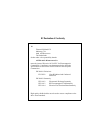
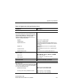
EC Declaration of Conformity
We
Tektronix Holland N.V.
Marktweg 73A
8444 AB Heerenveen
The Netherlands
declare under sole responsibility that the
AM700 Audio Measurement Set
meets the intent of Directive 89/336/EEC for Electromagnetic
Compatibility. Compliance was demonstrated to the following
specifications as listed in the Official Journal of the European
Communities:
EN 50081-1 Emissions:
EN 55022
Class B Radiated and Conducted
Emissions
EN 50082-1 Immunity:
IEC 801-2
Electrostatic Discharge Immunity
IEC 801-3
RF Electromagnetic Field Immunity
IEC 801-4
Electrical Fast Transient/Burst Immunity
High-quality shielded cables must be used to ensure compliance to the
above listed standards.
Table of Contents
General Safety Summary . . . . . . . . . . . . . . . . . . . . . . . . . . . . . . . . . . . . . . . . . . . . . . . .
xiii
Introduction and Installation
Key Features of the AM700 . . . . . . . . . . . . . . . . . . . . . . . . . . . . . . . . . . . . . . . . . . . .
Operation and Controls . . . . . . . . . . . . . . . . . . . . . . . . . . . . . . . . . . . . . . . . . . . . . . .
Measurement Capability . . . . . . . . . . . . . . . . . . . . . . . . . . . . . . . . . . . . . . . . . . . . . .
Audio Signal Generator Capabilities . . . . . . . . . . . . . . . . . . . . . . . . . . . . . . . . . . . . . .
Installation of the AM700 . . . . . . . . . . . . . . . . . . . . . . . . . . . . . . . . . . . . . . . . . . . . . .
Power Requirements . . . . . . . . . . . . . . . . . . . . . . . . . . . . . . . . . . . . . . . . . . . . .
Changing the Line Voltage Range and Fuse . . . . . . . . . . . . . . . . . . . . . . . . . . . .
Power Cord . . . . . . . . . . . . . . . . . . . . . . . . . . . . . . . . . . . . . . . . . . . . . . . . . . . .
Power Up Procedure . . . . . . . . . . . . . . . . . . . . . . . . . . . . . . . . . . . . . . . . . . . . .
Calibrating the Touch Screen . . . . . . . . . . . . . . . . . . . . . . . . . . . . . . . . . . . . . . .
Setting the AM700 Clock . . . . . . . . . . . . . . . . . . . . . . . . . . . . . . . . . . . . . . . . . .
Internal Backup Battery . . . . . . . . . . . . . . . . . . . . . . . . . . . . . . . . . . . . . . . . . . .
Options . . . . . . . . . . . . . . . . . . . . . . . . . . . . . . . . . . . . . . . . . . . . . . . . . . . . . . . . . .
Standard Accessories . . . . . . . . . . . . . . . . . . . . . . . . . . . . . . . . . . . . . . . . . . . . . . . .
Optional Accessories . . . . . . . . . . . . . . . . . . . . . . . . . . . . . . . . . . . . . . . . . . . . . . . .
User-supplied Accessories . . . . . . . . . . . . . . . . . . . . . . . . . . . . . . . . . . . . . . . . . . . .
1-1
1-2
1-3
1-3
1-4
1-4
1-5
1-6
1-6
1-8
1-10
1-11
1-11
1-12
1-12
1-12
Operating Basics
Touch Screen and Front Panel Buttons . . . . . . . . . . . . . . . . . . . . . . . . . . . . . . . . . . . .
Application Control . . . . . . . . . . . . . . . . . . . . . . . . . . . . . . . . . . . . . . . . . . . . . .
Display Icons . . . . . . . . . . . . . . . . . . . . . . . . . . . . . . . . . . . . . . . . . . . . . . . . . .
Views . . . . . . . . . . . . . . . . . . . . . . . . . . . . . . . . . . . . . . . . . . . . . . . . . . . . . . . .
Graphical Display Types . . . . . . . . . . . . . . . . . . . . . . . . . . . . . . . . . . . . . . . . . . .
Measurement Units . . . . . . . . . . . . . . . . . . . . . . . . . . . . . . . . . . . . . . . . . . . . . .
Front-panel Operation . . . . . . . . . . . . . . . . . . . . . . . . . . . . . . . . . . . . . . . . . . . . . . . .
Front Panel Button General Information . . . . . . . . . . . . . . . . . . . . . . . . . . . . . . . .
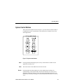
System Control Buttons . . . . . . . . . . . . . . . . . . . . . . . . . . . . . . . . . . . . . . . . . . . . . . .
AM700 Audio Measurement Set
2-1
2-4
2-4
2-4
2-6
2-7
2-8
2-8
2-9
i
Table of Contents
Menu . . . . . . . . . . . . . . . . . . . . . . . . . . . . . . . . . . . . . . . . . . . . . . . . . . . . . . . .
Limits . . . . . . . . . . . . . . . . . . . . . . . . . . . . . . . . . . . . . . . . . . . . . . . . . . . . . . . .
Rescale . . . . . . . . . . . . . . . . . . . . . . . . . . . . . . . . . . . . . . . . . . . . . . . . . . . . . .
Freeze . . . . . . . . . . . . . . . . . . . . . . . . . . . . . . . . . . . . . . . . . . . . . . . . . . . . . . .
Filter . . . . . . . . . . . . . . . . . . . . . . . . . . . . . . . . . . . . . . . . . . . . . . . . . . . . . . . . .
Cursors . . . . . . . . . . . . . . . . . . . . . . . . . . . . . . . . . . . . . . . . . . . . . . . . . . . . . .
Averaging . . . . . . . . . . . . . . . . . . . . . . . . . . . . . . . . . . . . . . . . . . . . . . . . . . . . .
Clear Menu . . . . . . . . . . . . . . . . . . . . . . . . . . . . . . . . . . . . . . . . . . . . . . . . . . . .
Applications Buttons . . . . . . . . . . . . . . . . . . . . . . . . . . . . . . . . . . . . . . . . . . . . . . . . .
Analyzer . . . . . . . . . . . . . . . . . . . . . . . . . . . . . . . . . . . . . . . . . . . . . . . . . . . . . .
Digital . . . . . . . . . . . . . . . . . . . . . . . . . . . . . . . . . . . . . . . . . . . . . . . . . . . . . . . .
Monitor . . . . . . . . . . . . . . . . . . . . . . . . . . . . . . . . . . . . . . . . . . . . . . . . . . . . . . .
FFT Analyzer . . . . . . . . . . . . . . . . . . . . . . . . . . . . . . . . . . . . . . . . . . . . . . . . . .
Other . . . . . . . . . . . . . . . . . . . . . . . . . . . . . . . . . . . . . . . . . . . . . . . . . . . . . . . .
User . . . . . . . . . . . . . . . . . . . . . . . . . . . . . . . . . . . . . . . . . . . . . . . . . . . . . . . . .
Utilities Buttons . . . . . . . . . . . . . . . . . . . . . . . . . . . . . . . . . . . . . . . . . . . . . . . . . . . . .
Configure . . . . . . . . . . . . . . . . . . . . . . . . . . . . . . . . . . . . . . . . . . . . . . . . . . . . .
Display . . . . . . . . . . . . . . . . . . . . . . . . . . . . . . . . . . . . . . . . . . . . . . . . . . . . . . .
Storage . . . . . . . . . . . . . . . . . . . . . . . . . . . . . . . . . . . . . . . . . . . . . . . . . . . . . .
Copy . . . . . . . . . . . . . . . . . . . . . . . . . . . . . . . . . . . . . . . . . . . . . . . . . . . . . . . .
Function . . . . . . . . . . . . . . . . . . . . . . . . . . . . . . . . . . . . . . . . . . . . . . . . . . . . . .
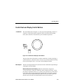
Control Knob and Display Control Buttons . . . . . . . . . . . . . . . . . . . . . . . . . . . . . . . . .
Control Knob . . . . . . . . . . . . . . . . . . . . . . . . . . . . . . . . . . . . . . . . . . . . . . . . . . .
Move/ Expand . . . . . . . . . . . . . . . . . . . . . . . . . . . . . . . . . . . . . . . . . . . . . . . . . .
Select . . . . . . . . . . . . . . . . . . . . . . . . . . . . . . . . . . . . . . . . . . . . . . . . . . . . . . . .
Generator Control Knobs and Buttons . . . . . . . . . . . . . . . . . . . . . . . . . . . . . . . . . . . .
Amplitude and Frequency Knobs . . . . . . . . . . . . . . . . . . . . . . . . . . . . . . . . . . . .
On . . . . . . . . . . . . . . . . . . . . . . . . . . . . . . . . . . . . . . . . . . . . . . . . . . . . . . . . . .
Control . . . . . . . . . . . . . . . . . . . . . . . . . . . . . . . . . . . . . . . . . . . . . . . . . . . . . . .
Audio Control Knob, Button, and Headphones . . . . . . . . . . . . . . . . . . . . . . . . . . . . . . .
On Button . . . . . . . . . . . . . . . . . . . . . . . . . . . . . . . . . . . . . . . . . . . . . . . . . . . . .
Volume Knob . . . . . . . . . . . . . . . . . . . . . . . . . . . . . . . . . . . . . . . . . . . . . . . . . .
Headphone Jack (1/4 inch Stereo) . . . . . . . . . . . . . . . . . . . . . . . . . . . . . . . . . . .
Sweep / Run Button . . . . . . . . . . . . . . . . . . . . . . . . . . . . . . . . . . . . . . . . . . . . . . . . .
Sweeps . . . . . . . . . . . . . . . . . . . . . . . . . . . . . . . . . . . . . . . . . . . . . . . . . . . . . .
ii
2-9
2-9
2-9
2-10
2-10
2-10
2-12
2-13
2-14
2-15
2-15
2-15
2-16
2-16
2-16
2-17
2-17
2-19
2-19
2-21
2-22
2-23
2-23
2-23
2-24
2-25
2-25
2-25
2-26
2-27
2-27
2-27
2-27
2-28
2-28
AM700 Audio Measurement Set
Table of Contents
Keypad Entry Buttons . . . . . . . . . . . . . . . . . . . . . . . . . . . . . . . . . . . . . . . . . . . . . . . .
Units Key . . . . . . . . . . . . . . . . . . . . . . . . . . . . . . . . . . . . . . . . . . . . . . . . . . . . .
Set Ref Key . . . . . . . . . . . . . . . . . . . . . . . . . . . . . . . . . . . . . . . . . . . . . . . . . . .
Front Panel Lock and Unlock . . . . . . . . . . . . . . . . . . . . . . . . . . . . . . . . . . . . . . .
Front-Panel Signal Connectors . . . . . . . . . . . . . . . . . . . . . . . . . . . . . . . . . . . . . . . . .
Analog Out . . . . . . . . . . . . . . . . . . . . . . . . . . . . . . . . . . . . . . . . . . . . . . . . . . . .
Analog In . . . . . . . . . . . . . . . . . . . . . . . . . . . . . . . . . . . . . . . . . . . . . . . . . . . . .
Digital Inputs and Outputs . . . . . . . . . . . . . . . . . . . . . . . . . . . . . . . . . . . . . . . . .
Floppy Disk Drive . . . . . . . . . . . . . . . . . . . . . . . . . . . . . . . . . . . . . . . . . . . . . . . . . . .
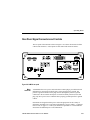
Rear-Panel Signal Connectors and Controls . . . . . . . . . . . . . . . . . . . . . . . . . . . . . . . .
Mains Connector . . . . . . . . . . . . . . . . . . . . . . . . . . . . . . . . . . . . . . . . . . . . . . . .
Power Switch, Fuse, and Trigger . . . . . . . . . . . . . . . . . . . . . . . . . . . . . . . . . . . .
Input/ Output Ports . . . . . . . . . . . . . . . . . . . . . . . . . . . . . . . . . . . . . . . . . . . . . .
Digital Input/ Output Connectors . . . . . . . . . . . . . . . . . . . . . . . . . . . . . . . . . . . . .
2-29
2-29
2-30
2-30
2-31
2-31
2-33
2-33
2-34
2-35
2-35
2-36
2-37
2-39
Configuring the AM700
AM700 Setup for Operation . . . . . . . . . . . . . . . . . . . . . . . . . . . . . . . . . . . . . . . . . . . .
Configuration . . . . . . . . . . . . . . . . . . . . . . . . . . . . . . . . . . . . . . . . . . . . . . . . . . . . . .
Input Selection . . . . . . . . . . . . . . . . . . . . . . . . . . . . . . . . . . . . . . . . . . . . . . . . .
View Setup . . . . . . . . . . . . . . . . . . . . . . . . . . . . . . . . . . . . . . . . . . . . . . . . . . . . . . . .
Measurement Setup Menu . . . . . . . . . . . . . . . . . . . . . . . . . . . . . . . . . . . . . . . . . . . . .
System Setup Menu . . . . . . . . . . . . . . . . . . . . . . . . . . . . . . . . . . . . . . . . . . . . . . . . .
Setting the System Clock . . . . . . . . . . . . . . . . . . . . . . . . . . . . . . . . . . . . . . . . . .
System Copy . . . . . . . . . . . . . . . . . . . . . . . . . . . . . . . . . . . . . . . . . . . . . . . . . .
System Communication Menu . . . . . . . . . . . . . . . . . . . . . . . . . . . . . . . . . . . . . . . . . . . . . . . . . . . . .
System Calibration Menu . . . . . . . . . . . . . . . . . . . . . . . . . . . . . . . . . . . . . . . . . .
System Conversion Standards Menu . . . . . . . . . . . . . . . . . . . . . . . . . . . . . . . . . .
Quick Setup . . . . . . . . . . . . . . . . . . . . . . . . . . . . . . . . . . . . . . . . . . . . . . . . . . . . . . .
3-1
3-2
3-2
3-7
3-11
3-13
3-13
3-13
3-16
3-17
3-18
3-22
Applications
Audio Generator . . . . . . . . . . . . . . . . . . . . . . . . . . . . . . . . . . . . . . . . . . . . . . . . . . . . . .
Capabilities . . . . . . . . . . . . . . . . . . . . . . . . . . . . . . . . . . . . . . . . . . . . . . . . . . . .
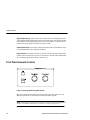
Front Panel Generator Controls . . . . . . . . . . . . . . . . . . . . . . . . . . . . . . . . . . . . . . . . .
Setting Up and Running the Generator . . . . . . . . . . . . . . . . . . . . . . . . . . . . . . . . . . . .
AM700 Audio Measurement Set
4-1
4-1
4-2
4-3
iii
Table of Contents
iv
Generator Selection . . . . . . . . . . . . . . . . . . . . . . . . . . . . . . . . . . . . . . . . . . . . . .
Assigning Control Knobs . . . . . . . . . . . . . . . . . . . . . . . . . . . . . . . . . . . . . . . . . .
Specifying an Output Waveform . . . . . . . . . . . . . . . . . . . . . . . . . . . . . . . . . . . . .
Multitone Files . . . . . . . . . . . . . . . . . . . . . . . . . . . . . . . . . . . . . . . . . . . . . . . . . .
Enabling Generator Output . . . . . . . . . . . . . . . . . . . . . . . . . . . . . . . . . . . . . . . . .
Selecting Digital Generator Mode . . . . . . . . . . . . . . . . . . . . . . . . . . . . . . . . . . . .
Adjusting Generator Frequency and Amplitude . . . . . . . . . . . . . . . . . . . . . . . . . . .
Waveform Control . . . . . . . . . . . . . . . . . . . . . . . . . . . . . . . . . . . . . . . . . . . . . . . . . . .
Sweep Control . . . . . . . . . . . . . . . . . . . . . . . . . . . . . . . . . . . . . . . . . . . . . . . . . . . . .
Sweep List . . . . . . . . . . . . . . . . . . . . . . . . . . . . . . . . . . . . . . . . . . . . . . . . . . . .
Advanced Digital Audio . . . . . . . . . . . . . . . . . . . . . . . . . . . . . . . . . . . . . . . . . . . . . . .
Creating a User Bits or Channel Status File . . . . . . . . . . . . . . . . . . . . . . . . . . . . .
Advanced Digital Interface . . . . . . . . . . . . . . . . . . . . . . . . . . . . . . . . . . . . . . . . . . . . .
Advanced Analog Controls . . . . . . . . . . . . . . . . . . . . . . . . . . . . . . . . . . . . . . . . . . . .
Changing Display Measurement Units in the Status Panel . . . . . . . . . . . . . . . . . . . . . .
Set Reference . . . . . . . . . . . . . . . . . . . . . . . . . . . . . . . . . . . . . . . . . . . . . . . . . . . . .
4-4
4-4
4-5
4-9
4-14
4-14
4-15
4-17
4-19
4-21
4-24
4-26
4-29
4-32
4-34
4-35
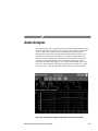
Audio Analyzer . . . . . . . . . . . . . . . . . . . . . . . . . . . . . . . . . . . . . . . . . . . . . . . . . . . . . . .
XY Measurement Mode . . . . . . . . . . . . . . . . . . . . . . . . . . . . . . . . . . . . . . . . . . . . . . .
Regulation Mode Measurements . . . . . . . . . . . . . . . . . . . . . . . . . . . . . . . . . . . . . . . .
Making a Closed-Loop XY Measurement . . . . . . . . . . . . . . . . . . . . . . . . . . . . . . . . . .
Audio Analyzer Setup . . . . . . . . . . . . . . . . . . . . . . . . . . . . . . . . . . . . . . . . . . . .
Generator and Waveform Selection . . . . . . . . . . . . . . . . . . . . . . . . . . . . . . . . . . .
Connecting the Signal . . . . . . . . . . . . . . . . . . . . . . . . . . . . . . . . . . . . . . . . . . . .
Selecting a View to Display the Measurement . . . . . . . . . . . . . . . . . . . . . . . . . . .
Related Information . . . . . . . . . . . . . . . . . . . . . . . . . . . . . . . . . . . . . . . . . . . . . .
Making Valid Measurements . . . . . . . . . . . . . . . . . . . . . . . . . . . . . . . . . . . . . . . . . . .
Configuring Input Channels . . . . . . . . . . . . . . . . . . . . . . . . . . . . . . . . . . . . . . . . . . . .
Selecting Input Options . . . . . . . . . . . . . . . . . . . . . . . . . . . . . . . . . . . . . . . . . . . . . . .
Real Time Readout of Measurements . . . . . . . . . . . . . . . . . . . . . . . . . . . . . . . . . . . . .
Enabling and Disabling Measurements . . . . . . . . . . . . . . . . . . . . . . . . . . . . . . . .
Wow and Flutter Measurement . . . . . . . . . . . . . . . . . . . . . . . . . . . . . . . . . . . . . .
4-37
4-38
4-40
4-45
4-46
4-48
4-49
4-50
4-51
4-52
4-52
4-53
4-55
4-56
4-57
AM700 Audio Measurement Set
Table of Contents
Controlling Plotted Data . . . . . . . . . . . . . . . . . . . . . . . . . . . . . . . . . . . . . . . . . . . . . . .
Enable . . . . . . . . . . . . . . . . . . . . . . . . . . . . . . . . . . . . . . . . . . . . . . . . . . . . . . .
History . . . . . . . . . . . . . . . . . . . . . . . . . . . . . . . . . . . . . . . . . . . . . . . . . . . . . . .
Begin New Plot . . . . . . . . . . . . . . . . . . . . . . . . . . . . . . . . . . . . . . . . . . . . . . . . .
Erase All Plots . . . . . . . . . . . . . . . . . . . . . . . . . . . . . . . . . . . . . . . . . . . . . . . . . .
Erase Current Plot . . . . . . . . . . . . . . . . . . . . . . . . . . . . . . . . . . . . . . . . . . . . . . .
Configuring Measurements . . . . . . . . . . . . . . . . . . . . . . . . . . . . . . . . . . . . . . . . . . . .
General Controls . . . . . . . . . . . . . . . . . . . . . . . . . . . . . . . . . . . . . . . . . . . . . . . .
Sweep Detection Controls . . . . . . . . . . . . . . . . . . . . . . . . . . . . . . . . . . . . . . . . .
Sweep Detection Attributes . . . . . . . . . . . . . . . . . . . . . . . . . . . . . . . . . . . . . . . .
Sweep Source . . . . . . . . . . . . . . . . . . . . . . . . . . . . . . . . . . . . . . . . . . . . . . . . . .
Settled Data Point Detection Controls . . . . . . . . . . . . . . . . . . . . . . . . . . . . . . . . .
Relative to Reference Controls . . . . . . . . . . . . . . . . . . . . . . . . . . . . . . . . . . . . . .
View Setup . . . . . . . . . . . . . . . . . . . . . . . . . . . . . . . . . . . . . . . . . . . . . . . . . . . .
Input Filtering . . . . . . . . . . . . . . . . . . . . . . . . . . . . . . . . . . . . . . . . . . . . . . . . . . . . . .
Cursors . . . . . . . . . . . . . . . . . . . . . . . . . . . . . . . . . . . . . . . . . . . . . . . . . . . . . . . . . .
Generator Status Readout . . . . . . . . . . . . . . . . . . . . . . . . . . . . . . . . . . . . . . . . . . . . .
4-58
4-58
4-58
4-58
4-59
4-59
4-60
4-60
4-61
4-62
4-63
4-65
4-70
4-74
4-75
4-80
4-80
FFT Analyzer . . . . . . . . . . . . . . . . . . . . . . . . . . . . . . . . . . . . . . . . . . . . . . . . . . . . . . . . .
Measurement Bandwidth . . . . . . . . . . . . . . . . . . . . . . . . . . . . . . . . . . . . . . . . . . . . . .
Windowing . . . . . . . . . . . . . . . . . . . . . . . . . . . . . . . . . . . . . . . . . . . . . . . . . . . . . . . .
Measurement Modes . . . . . . . . . . . . . . . . . . . . . . . . . . . . . . . . . . . . . . . . . . . . . . . .
Displays . . . . . . . . . . . . . . . . . . . . . . . . . . . . . . . . . . . . . . . . . . . . . . . . . . . . . . . . . .
Input Range . . . . . . . . . . . . . . . . . . . . . . . . . . . . . . . . . . . . . . . . . . . . . . . . . . . . . . .
Cursors . . . . . . . . . . . . . . . . . . . . . . . . . . . . . . . . . . . . . . . . . . . . . . . . . . . . . . . . . .
Averaging . . . . . . . . . . . . . . . . . . . . . . . . . . . . . . . . . . . . . . . . . . . . . . . . . . . . . . . .
Zooming (Expanding) the Display . . . . . . . . . . . . . . . . . . . . . . . . . . . . . . . . . . . . . . . .
Multitone Measurement Mode . . . . . . . . . . . . . . . . . . . . . . . . . . . . . . . . . . . . . . . . . .
Multitone Detection . . . . . . . . . . . . . . . . . . . . . . . . . . . . . . . . . . . . . . . . . . . . . .
Multitone Mode Measurements and Graphical Displays . . . . . . . . . . . . . . . . . . . .
4-81
4-82
4-82
4-85
4-85
4-87
4-88
4-89
4-89
4-90
4-91
4-92
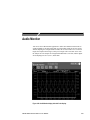
Audio Monitor . . . . . . . . . . . . . . . . . . . . . . . . . . . . . . . . . . . . . . . . . . . . . . . . . . . . . . . .
Displays . . . . . . . . . . . . . . . . . . . . . . . . . . . . . . . . . . . . . . . . . . . . . . . . . . . . . . . . . .
View Setup . . . . . . . . . . . . . . . . . . . . . . . . . . . . . . . . . . . . . . . . . . . . . . . . . . . .
Cursors . . . . . . . . . . . . . . . . . . . . . . . . . . . . . . . . . . . . . . . . . . . . . . . . . . . . . . . . . .
Menu . . . . . . . . . . . . . . . . . . . . . . . . . . . . . . . . . . . . . . . . . . . . . . . . . . . . . . . . . . . .
4-97
4-98
4-99
4-101
4-103
AM700 Audio Measurement Set
v
Table of Contents
Input Select . . . . . . . . . . . . . . . . . . . . . . . . . . . . . . . . . . . . . . . . . . . . . . . . . . . .
Trigger Selects . . . . . . . . . . . . . . . . . . . . . . . . . . . . . . . . . . . . . . . . . . . . . . . . .
4-103
4-104
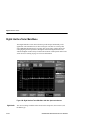
Digital Interface Tester . . . . . . . . . . . . . . . . . . . . . . . . . . . . . . . . . . . . . . . . . . . . . . . . . .
Digital Interface Tester Input Configuration . . . . . . . . . . . . . . . . . . . . . . . . . . . . . . . . .
View Setup . . . . . . . . . . . . . . . . . . . . . . . . . . . . . . . . . . . . . . . . . . . . . . . . . . . . . . . .
View Selection Bar . . . . . . . . . . . . . . . . . . . . . . . . . . . . . . . . . . . . . . . . . . . . . .
Bit Probability Display . . . . . . . . . . . . . . . . . . . . . . . . . . . . . . . . . . . . . . . . . . . . . . . .
Channel Status Display . . . . . . . . . . . . . . . . . . . . . . . . . . . . . . . . . . . . . . . . . . . . . . .
Eye Diagram Display . . . . . . . . . . . . . . . . . . . . . . . . . . . . . . . . . . . . . . . . . . . . . . . . .
Digital Jitter Measurement . . . . . . . . . . . . . . . . . . . . . . . . . . . . . . . . . . . . . . . . . . . . .
Jitter Spectrum View Types . . . . . . . . . . . . . . . . . . . . . . . . . . . . . . . . . . . . . . . .
Digital Interface Tester Main Menu . . . . . . . . . . . . . . . . . . . . . . . . . . . . . . . . . . . . . . .
Digital Audio . . . . . . . . . . . . . . . . . . . . . . . . . . . . . . . . . . . . . . . . . . . . . . . . . . .
Interface Timing . . . . . . . . . . . . . . . . . . . . . . . . . . . . . . . . . . . . . . . . . . . . . . . .
Interface Amplitude . . . . . . . . . . . . . . . . . . . . . . . . . . . . . . . . . . . . . . . . . . . . . .
Jitter Generation . . . . . . . . . . . . . . . . . . . . . . . . . . . . . . . . . . . . . . . . . . . . . . . .
Eye/Jitter Detection . . . . . . . . . . . . . . . . . . . . . . . . . . . . . . . . . . . . . . . . . . . . . .
Subframe Format . . . . . . . . . . . . . . . . . . . . . . . . . . . . . . . . . . . . . . . . . . . . . . . . . . .
Digital Interface Terminology . . . . . . . . . . . . . . . . . . . . . . . . . . . . . . . . . . . . . . . . . . .
4-107
4-108
4-110
4-111
4-112
4-113
4-116
4-119
4-120
4-122
4-122
4-123
4-123
4-124
4-125
4-125
4-127
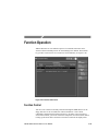
Function Operation . . . . . . . . . . . . . . . . . . . . . . . . . . . . . . . . . . . . . . . . . . . . . . . . . . . .
Function Control . . . . . . . . . . . . . . . . . . . . . . . . . . . . . . . . . . . . . . . . . . . . . . . . . . . .
Running a Function . . . . . . . . . . . . . . . . . . . . . . . . . . . . . . . . . . . . . . . . . . . . . .
Writing a Function . . . . . . . . . . . . . . . . . . . . . . . . . . . . . . . . . . . . . . . . . . . . . . .
Editing Function Key Programs . . . . . . . . . . . . . . . . . . . . . . . . . . . . . . . . . . . . . .
Loading Function Programs . . . . . . . . . . . . . . . . . . . . . . . . . . . . . . . . . . . . . . . .
AM700 Storage Manager . . . . . . . . . . . . . . . . . . . . . . . . . . . . . . . . . . . . . . . . . .
Timed Functions . . . . . . . . . . . . . . . . . . . . . . . . . . . . . . . . . . . . . . . . . . . . . . . .
Save AM700 State Function . . . . . . . . . . . . . . . . . . . . . . . . . . . . . . . . . . . . . . . .
4-129
4-129
4-130
4-130
4-132
4-132
4-132
4-134
4-136
Appendices
Appendix A: Specifications . . . . . . . . . . . . . . . . . . . . . . . . . . . . . . . . . . . . . . . . . . . . . .
A-1
Index
vi
AM700 Audio Measurement Set
Table of Contents
List of Figures
Figure 1-1: Rear panel fuse, power connector, On/Off Switch, and line selector . . . . . . . . . . . . . . . . .
Figure 1-2: Application selection menu under the Other button . . . . . . . . . . . . . . . . . . . . . . . . . . . . .
Figure 1-3: Touch screen calibration . . . . . . . . . . . . . . . . . . . . . . . . . . . . . . . . . . . . . . . . . . . . . . . .
Figure 1-4: AM700 System Clock . . . . . . . . . . . . . . . . . . . . . . . . . . . . . . . . . . . . . . . . . . . . . . . . . .
Figure 2-1: Touch screen interface without menus . . . . . . . . . . . . . . . . . . . . . . . . . . . . . . . . . . . . . .
Figure 2-2: Touch screen interface with main menus and submenus displayed . . . . . . . . . . . . . . . . . .
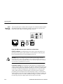
Figure 2-3: Representative icons and arrows seen in the AM700 display . . . . . . . . . . . . . . . . . . . . . .
Figure 2-4: Views selection bar with only View 1 selected for display . . . . . . . . . . . . . . . . . . . . . . . . .
Figure 2-5: View windows and control assignment . . . . . . . . . . . . . . . . . . . . . . . . . . . . . . . . . . . . . .
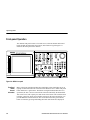
Figure 2-6: AM700 front panel . . . . . . . . . . . . . . . . . . . . . . . . . . . . . . . . . . . . . . . . . . . . . . . . . . . .
Figure 2-7: System control buttons . . . . . . . . . . . . . . . . . . . . . . . . . . . . . . . . . . . . . . . . . . . . . . . . .
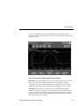
Figure 2-8: Cursor menu showing frequency and level readouts . . . . . . . . . . . . . . . . . . . . . . . . . . . .
Figure 2-9: Average menu and FFT trace with averaging applied . . . . . . . . . . . . . . . . . . . . . . . . . . . .
Figure 2-10: Applications buttons . . . . . . . . . . . . . . . . . . . . . . . . . . . . . . . . . . . . . . . . . . . . . . . . . .
Figure 2-11: Utilities buttons . . . . . . . . . . . . . . . . . . . . . . . . . . . . . . . . . . . . . . . . . . . . . . . . . . . . . .
Figure 2-12: System Status display . . . . . . . . . . . . . . . . . . . . . . . . . . . . . . . . . . . . . . . . . . . . . . . . .
Figure 2-13: Storage Manager control screen . . . . . . . . . . . . . . . . . . . . . . . . . . . . . . . . . . . . . . . . .
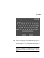
Figure 2-14: File renaming keyboard . . . . . . . . . . . . . . . . . . . . . . . . . . . . . . . . . . . . . . . . . . . . . . . .
Figure 2-15: Control knob and display control buttons . . . . . . . . . . . . . . . . . . . . . . . . . . . . . . . . . . . .
Figure 2-16: Audio Generator controls . . . . . . . . . . . . . . . . . . . . . . . . . . . . . . . . . . . . . . . . . . . . . . .
Figure 2-17: The Generator Control panel . . . . . . . . . . . . . . . . . . . . . . . . . . . . . . . . . . . . . . . . . . . .
Figure 2-18: Headphone audio controls . . . . . . . . . . . . . . . . . . . . . . . . . . . . . . . . . . . . . . . . . . . . . .
Figure 2-19: Sweep/Run button and LED indicator . . . . . . . . . . . . . . . . . . . . . . . . . . . . . . . . . . . . . .
Figure 2-20: Keypad entry buttons . . . . . . . . . . . . . . . . . . . . . . . . . . . . . . . . . . . . . . . . . . . . . . . . .
Figure 2-21: Front-panel signal connectors . . . . . . . . . . . . . . . . . . . . . . . . . . . . . . . . . . . . . . . . . . .
Figure 2-22: Analog XLR connector pin outs . . . . . . . . . . . . . . . . . . . . . . . . . . . . . . . . . . . . . . . . . .
Figure 2-23: Driving an unbalanced load with the AM700 generator . . . . . . . . . . . . . . . . . . . . . . . . . .
Figure 2-24: Disk drive . . . . . . . . . . . . . . . . . . . . . . . . . . . . . . . . . . . . . . . . . . . . . . . . . . . . . . . . . .
Figure 2-25: AM700 rear panel . . . . . . . . . . . . . . . . . . . . . . . . . . . . . . . . . . . . . . . . . . . . . . . . . . . .
Figure 2-26: Mains connector, power switch, fuse, and line selector . . . . . . . . . . . . . . . . . . . . . . . . . .
Figure 2-27: Analog TTL-level trigger input connector . . . . . . . . . . . . . . . . . . . . . . . . . . . . . . . . . . . .
Figure 2-28: COM1 and COM2 serial ports . . . . . . . . . . . . . . . . . . . . . . . . . . . . . . . . . . . . . . . . . . .
Figure 2-29: Keyboard and VGA video connectors . . . . . . . . . . . . . . . . . . . . . . . . . . . . . . . . . . . . . .
AM700 Audio Measurement Set
1-5
1-8
1-9
1-10
2-1
2-3
2-5
2-6
2-7
2-8
2-9
2-11
2-13
2-14
2-17
2-19
2-20
2-21
2-23
2-25
2-26
2-27
2-28
2-29
2-31
2-31
2-32
2-34
2-35
2-36
2-37
2-38
2-38
vii
Table of Contents
Figure 2-30: GPIB connector . . . . . . . . . . . . . . . . . . . . . . . . . . . . . . . . . . . . . . . . . . . . . . . . . . . . .
Figure 2-31: Remote contact-closure connector . . . . . . . . . . . . . . . . . . . . . . . . . . . . . . . . . . . . . . . .
Figure 2-32: Digital audio connectors . . . . . . . . . . . . . . . . . . . . . . . . . . . . . . . . . . . . . . . . . . . . . . .
Figure 2-33: Digital signal processor port connector . . . . . . . . . . . . . . . . . . . . . . . . . . . . . . . . . . . . .
Figure 2-34: DSP port timing diagram . . . . . . . . . . . . . . . . . . . . . . . . . . . . . . . . . . . . . . . . . . . . . . .
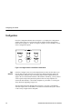
Figure 3-1: Applications selection buttons . . . . . . . . . . . . . . . . . . . . . . . . . . . . . . . . . . . . . . . . . . . .
Figure 3-2: Configure button in the Utilities selection block . . . . . . . . . . . . . . . . . . . . . . . . . . . . . . . .
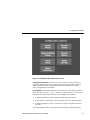
Figure 3-3: Configuration menu initial selection screen . . . . . . . . . . . . . . . . . . . . . . . . . . . . . . . . . . .
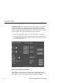
Figure 3-4: Input Configuration control panel . . . . . . . . . . . . . . . . . . . . . . . . . . . . . . . . . . . . . . . . . .
Figure 3-5: Measurement channel assignment pull-down menu . . . . . . . . . . . . . . . . . . . . . . . . . . . . .
Figure 3-6: A typical View Setup control menu . . . . . . . . . . . . . . . . . . . . . . . . . . . . . . . . . . . . . . . . .
Figure 3-7: FFT Analyzer View Options in the View Setup controls . . . . . . . . . . . . . . . . . . . . . . . . . .
Figure 3-8: Four different measurements in the four views of Audio Analyzer . . . . . . . . . . . . . . . . . . .
Figure 3-9: FFT Analyzer configure measurement screens for FFT and for Multitone . . . . . . . . . . . . . .
Figure 3-10: The Copy Configuration menu . . . . . . . . . . . . . . . . . . . . . . . . . . . . . . . . . . . . . . . . . . .
Figure 3-11: Hard copy output file selector . . . . . . . . . . . . . . . . . . . . . . . . . . . . . . . . . . . . . . . . . . . .
Figure 3-12: System Setup Communicate Configuration menu . . . . . . . . . . . . . . . . . . . . . . . . . . . . .
Figure 3-13: System Setup Conversion Standards menu . . . . . . . . . . . . . . . . . . . . . . . . . . . . . . . . .
Figure 3-14: AM700 generator output voltage divider for dBm calculations . . . . . . . . . . . . . . . . . . . . .
Figure 3-15: AM700 input circuit for dBm calculation . . . . . . . . . . . . . . . . . . . . . . . . . . . . . . . . . . . . .
Figure 3-16: Quick Setup selections for Audio Analyzer . . . . . . . . . . . . . . . . . . . . . . . . . . . . . . . . . .
Figure 4-1: Audio generator front panel controls . . . . . . . . . . . . . . . . . . . . . . . . . . . . . . . . . . . . . . . .
Figure 4-2: The Generator Selection display . . . . . . . . . . . . . . . . . . . . . . . . . . . . . . . . . . . . . . . . . .
Figure 4-3: Amplitude and Frequency control knob assignment selectors . . . . . . . . . . . . . . . . . . . . . .
Figure 4-4: Generator status panel in an FFT Analyzer display . . . . . . . . . . . . . . . . . . . . . . . . . . . . .
Figure 4-5: Generator status panel . . . . . . . . . . . . . . . . . . . . . . . . . . . . . . . . . . . . . . . . . . . . . . . . .
Figure 4-6: Waveform control display . . . . . . . . . . . . . . . . . . . . . . . . . . . . . . . . . . . . . . . . . . . . . . .
Figure 4-7: Sweep control display . . . . . . . . . . . . . . . . . . . . . . . . . . . . . . . . . . . . . . . . . . . . . . . . . .
Figure 4-8: The List Editor display . . . . . . . . . . . . . . . . . . . . . . . . . . . . . . . . . . . . . . . . . . . . . . . . . .
Figure 4-9: Advanced Digital Audio display . . . . . . . . . . . . . . . . . . . . . . . . . . . . . . . . . . . . . . . . . . .
Figure 4-10: User Bit filename selection list . . . . . . . . . . . . . . . . . . . . . . . . . . . . . . . . . . . . . . . . . . .
Figure 4-11: Advanced Digital Interface display . . . . . . . . . . . . . . . . . . . . . . . . . . . . . . . . . . . . . . . .
Figure 4-12: The Advanced Analog Controls display . . . . . . . . . . . . . . . . . . . . . . . . . . . . . . . . . . . .
Figure 4-13: Units menu with choice for voltage units shown . . . . . . . . . . . . . . . . . . . . . . . . . . . . . . .
Figure 4-14: Audio Analyzer graphical display with real time (RT) view visible . . . . . . . . . . . . . . . . . . .
Figure 4-15: General controls XY Measurement mode menu selections . . . . . . . . . . . . . . . . . . . . . . .
viii
2-39
2-39
2-40
2-42
2-43
3-1
3-2
3-3
3-4
3-6
3-7
3-9
3-11
3-12
3-14
3-16
3-17
3-19
3-20
3-20
3-22
4-2
4-3
4-5
4-15
4-16
4-18
4-20
4-23
4-24
4-28
4-30
4-32
4-34
4-37
4-39
AM700 Audio Measurement Set
Table of Contents
Figure 4-16: General controls with Regulation mode menu selections . . . . . . . . . . . . . . . . . . . . . . . .
Figure 4-17: Regulation mode with Plot Control menu . . . . . . . . . . . . . . . . . . . . . . . . . . . . . . . . . . .
Figure 4-18: View Setup for Regulation mode measurements . . . . . . . . . . . . . . . . . . . . . . . . . . . . . .
Figure 4-19: Regulation mode bandpass measurement of level versus frequency . . . . . . . . . . . . . . . .
Figure 4-20: History display of Channel 2 THD versus frequency obtained using
closed-loop operation . . . . . . . . . . . . . . . . . . . . . . . . . . . . . . . . . . . . . . . . . . . . . . . . . . . . . . .
Figure 4-21: Audio Analyzer main menu with Input Range and Input Select submenus . . . . . . . . . . . .
Figure 4-22: Audio Analyzer Real Time Measurements and Generator Setup display . . . . . . . . . . . . .
Figure 4-23: Audio Analyzer graphical display showing measurement Enables menu selections . . . . . .
Figure 4-24: Graphical display with Plot Control menu . . . . . . . . . . . . . . . . . . . . . . . . . . . . . . . . . . .
Figure 4-25: Sweep detection controls . . . . . . . . . . . . . . . . . . . . . . . . . . . . . . . . . . . . . . . . . . . . . .
Figure 4-26: Closed-loop measurement showing how delay, settling time, and variance
affect the generator steps . . . . . . . . . . . . . . . . . . . . . . . . . . . . . . . . . . . . . . . . . . . . . . . . . . . .
Figure 4-27: Settled data point detection controls display . . . . . . . . . . . . . . . . . . . . . . . . . . . . . . . . .
Figure 4-28: Exponential settling in Audio Analyzer . . . . . . . . . . . . . . . . . . . . . . . . . . . . . . . . . . . . .
Figure 4-29: Regulation mode delay time setting . . . . . . . . . . . . . . . . . . . . . . . . . . . . . . . . . . . . . . .
Figure 4-30: Rel to Ref memory model . . . . . . . . . . . . . . . . . . . . . . . . . . . . . . . . . . . . . . . . . . . . . .
Figure 4-31: Relative to Reference setup menu . . . . . . . . . . . . . . . . . . . . . . . . . . . . . . . . . . . . . . . .
Figure 4-32: Filter menu selection with Audio Analyzer . . . . . . . . . . . . . . . . . . . . . . . . . . . . . . . . . . .
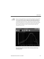
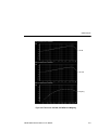
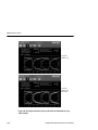
Figure 4-33: Filter curves: CCIR 468, CCIR ARM, and A Weighting . . . . . . . . . . . . . . . . . . . . . . . . . .
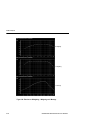
Figure 4-34: Filter Curves: B Weighting, C Weighting, and C Message . . . . . . . . . . . . . . . . . . . . . . . .
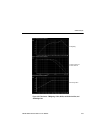
Figure 4-35: Filter Curves: F Weighting, 15 kHz, 20 kHz, and 22 kHz Low Pass,
and 400 Hz High Pass . . . . . . . . . . . . . . . . . . . . . . . . . . . . . . . . . . . . . . . . . . . . . . . . . . . . . .
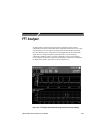
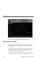
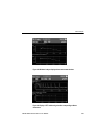
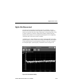
Figure 4-36: FFT Analyzer measurement showing a dual channel spectral display . . . . . . . . . . . . . . .
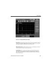
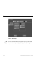
Figure 4-37: FFT Analyzer Window menu display . . . . . . . . . . . . . . . . . . . . . . . . . . . . . . . . . . . . . .
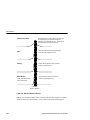
Figure 4-38: Effects of Window selections . . . . . . . . . . . . . . . . . . . . . . . . . . . . . . . . . . . . . . . . . . . .
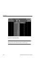
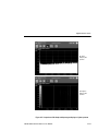
Figure 4-39: FFT Bar graph and Spectrogram displays . . . . . . . . . . . . . . . . . . . . . . . . . . . . . . . . . . .
Figure 4-40: FFT Input Select and Input Range menus . . . . . . . . . . . . . . . . . . . . . . . . . . . . . . . . . . .
Figure 4-41: Zoomed FFT display showing maximum expansion of the trace . . . . . . . . . . . . . . . . . . .
Figure 4-42: Generator Waveform Control setup for multitone detection . . . . . . . . . . . . . . . . . . . . . . .
Figure 4-43: Multitone measurement settings in the Configure Measurements menu . . . . . . . . . . . . . .
Figure 4-44: FFT View Setup . . . . . . . . . . . . . . . . . . . . . . . . . . . . . . . . . . . . . . . . . . . . . . . . . . . . .
Figure 4-45: Multitone Analyzer display with two measurement windows . . . . . . . . . . . . . . . . . . . . . .
Figure 4-46: Display of FFT multitone signal and the corresponding multitone measurement . . . . . . . .
Figure 4-47: FFT multitone table display . . . . . . . . . . . . . . . . . . . . . . . . . . . . . . . . . . . . . . . . . . . . .
Figure 4-48: Audio Monitor display with dual Y-axis display . . . . . . . . . . . . . . . . . . . . . . . . . . . . . . . .
AM700 Audio Measurement Set
4-40
4-43
4-44
4-45
4-51
4-54
4-55
4-56
4-59
4-62
4-65
4-66
4-67
4-68
4-72
4-73
4-76
4-77
4-78
4-79
4-81
4-83
4-84
4-86
4-88
4-90
4-91
4-93
4-94
4-95
4-95
4-96
4-97
ix
Table of Contents
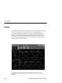
Figure 4-49: Dual channel display showing different signals on Channel 1 and Channel 2 . . . . . . . . . .
Figure 4-50: The View Setup screen for Audio Monitor . . . . . . . . . . . . . . . . . . . . . . . . . . . . . . . . . .
Figure 4-51: View Options in the View Setup controls . . . . . . . . . . . . . . . . . . . . . . . . . . . . . . . . . . . .
Figure 4-52: Use of Cursors to measure pulse time . . . . . . . . . . . . . . . . . . . . . . . . . . . . . . . . . . . . .
Figure 4-53: Input selections in Audio Monitor menu . . . . . . . . . . . . . . . . . . . . . . . . . . . . . . . . . . . . .
Figure 4-54: Triggering selections in Audio Monitor menu . . . . . . . . . . . . . . . . . . . . . . . . . . . . . . . . .
Figure 4-55: Audio Monitor Trigger Controls In the Configure menu under setup measurements . . . . . .
Figure 4-56: Digital Interface Tester Input Configuration menu . . . . . . . . . . . . . . . . . . . . . . . . . . . . . .
Figure 4-57: Digital Interface Tester View Setup controls . . . . . . . . . . . . . . . . . . . . . . . . . . . . . . . . . .
Figure 4-58: Digital Interface Tester view selection bar showing Bit Activity selected . . . . . . . . . . . . . .
Figure 4-59: Bit Probability display with 24-bit digital data . . . . . . . . . . . . . . . . . . . . . . . . . . . . . . . . .
Figure 4-60: 1/0 Display showing byte-by-byte binary data . . . . . . . . . . . . . . . . . . . . . . . . . . . . . . . .
Figure 4-61: 1/0 View Options menu . . . . . . . . . . . . . . . . . . . . . . . . . . . . . . . . . . . . . . . . . . . . . . . .
Figure 4-62: Decoded channel-status data display . . . . . . . . . . . . . . . . . . . . . . . . . . . . . . . . . . . . . .
Figure 4-63: Digital Interface Tester eye diagram . . . . . . . . . . . . . . . . . . . . . . . . . . . . . . . . . . . . . . .
Figure 4-64: Eye Diagram with jitter and long cable effects simulated with the Long Cable
simulator . . . . . . . . . . . . . . . . . . . . . . . . . . . . . . . . . . . . . . . . . . . . . . . . . . . . . . . . . . . . . . . .
Figure 4-65: Jitter Spectrum display . . . . . . . . . . . . . . . . . . . . . . . . . . . . . . . . . . . . . . . . . . . . . . . .
Figure 4-66: Jitter View Types . . . . . . . . . . . . . . . . . . . . . . . . . . . . . . . . . . . . . . . . . . . . . . . . . . . .
Figure 4-67: Comparison of Bar Graph and Spectrogram displays of a jitter spectrum . . . . . . . . . . . . .
Figure 4-68: Digital Interface Tester Main Menu with Jitter Spectrum submenus . . . . . . . . . . . . . . . . .
Figure 4-69: AES serial digital subframe formats . . . . . . . . . . . . . . . . . . . . . . . . . . . . . . . . . . . . . . .
Figure 4-70: Function control menu . . . . . . . . . . . . . . . . . . . . . . . . . . . . . . . . . . . . . . . . . . . . . . . . .
Figure 4-71: Storage Manager control screen . . . . . . . . . . . . . . . . . . . . . . . . . . . . . . . . . . . . . . . . .
x
4-98
4-99
4-101
4-102
4-103
4-104
4-105
4-109
4-110
4-111
4-112
4-113
4-114
4-115
4-116
4-118
4-119
4-120
4-121
4-122
4-125
4-129
4-133
AM700 Audio Measurement Set
Table of Contents
List of Tables
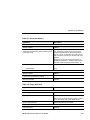
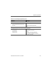
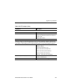
Table 1-1: Optional Power Cords . . . . . . . . . . . . . . . . . . . . . . . . . . . . . . . . . . . . . . . . . . . . . .
Table 3-1: Quick Setups by Application . . . . . . . . . . . . . . . . . . . . . . . . . . . . . . . . . . . . . . . . . .
Table 4-1: Subframe Time Slots . . . . . . . . . . . . . . . . . . . . . . . . . . . . . . . . . . . . . . . . . . . . . . .
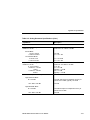
Table A-1: Analog Analyzer Specifications . . . . . . . . . . . . . . . . . . . . . . . . . . . . . . . . . . . . . . . .
Table A-2: Electronic Triggers Specifications . . . . . . . . . . . . . . . . . . . . . . . . . . . . . . . . . . . . . .
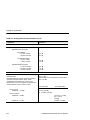
Table A-3: Analog Generator Specifications . . . . . . . . . . . . . . . . . . . . . . . . . . . . . . . . . . . . . . .
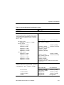
Table A-4: Digital Audio Unit Specifications . . . . . . . . . . . . . . . . . . . . . . . . . . . . . . . . . . . . . . .
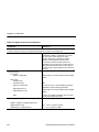
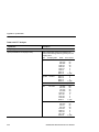
Table A-5: Display System . . . . . . . . . . . . . . . . . . . . . . . . . . . . . . . . . . . . . . . . . . . . . . . . . .
Table A-6: Software Update Procedure . . . . . . . . . . . . . . . . . . . . . . . . . . . . . . . . . . . . . . . . . .
Table A-7: Nonvolatile Memory . . . . . . . . . . . . . . . . . . . . . . . . . . . . . . . . . . . . . . . . . . . . . . . .
Table A-8: Floppy Disk Drive . . . . . . . . . . . . . . . . . . . . . . . . . . . . . . . . . . . . . . . . . . . . . . . . .
Table A-9: Front Panel Hardware . . . . . . . . . . . . . . . . . . . . . . . . . . . . . . . . . . . . . . . . . . . . . .
Table A-10: Rear Panel Hardware . . . . . . . . . . . . . . . . . . . . . . . . . . . . . . . . . . . . . . . . . . . . .
Table A-11: Power Distribution System . . . . . . . . . . . . . . . . . . . . . . . . . . . . . . . . . . . . . . . . . .
Table A-12: Safety Standards . . . . . . . . . . . . . . . . . . . . . . . . . . . . . . . . . . . . . . . . . . . . . . . . .
Table A-13: Safety Certification Compliance . . . . . . . . . . . . . . . . . . . . . . . . . . . . . . . . . . . . . .
Table A-14: Environmental Characteristics . . . . . . . . . . . . . . . . . . . . . . . . . . . . . . . . . . . . . . .
Table A-15: Dynamic Characteristics . . . . . . . . . . . . . . . . . . . . . . . . . . . . . . . . . . . . . . . . . . . .
Table A-16: Electromagnetic Compatibility . . . . . . . . . . . . . . . . . . . . . . . . . . . . . . . . . . . . . . . .
Table A-17: Mechanical Characteristics . . . . . . . . . . . . . . . . . . . . . . . . . . . . . . . . . . . . . . . . . .
Table A-18: Remote Control Protocol . . . . . . . . . . . . . . . . . . . . . . . . . . . . . . . . . . . . . . . . . . .
Table A-19: Generator Control . . . . . . . . . . . . . . . . . . . . . . . . . . . . . . . . . . . . . . . . . . . . . . . .
Table A-20: Generator Signals . . . . . . . . . . . . . . . . . . . . . . . . . . . . . . . . . . . . . . . . . . . . . . . .
Table A-21: Audio Analyzer Application . . . . . . . . . . . . . . . . . . . . . . . . . . . . . . . . . . . . . . . . . .
Table A-22: FFT Analyzer . . . . . . . . . . . . . . . . . . . . . . . . . . . . . . . . . . . . . . . . . . . . . . . . . . .
Table A-23: Audio Monitor . . . . . . . . . . . . . . . . . . . . . . . . . . . . . . . . . . . . . . . . . . . . . . . . . . .
Table A-24: Digital Interface Tester . . . . . . . . . . . . . . . . . . . . . . . . . . . . . . . . . . . . . . . . . . . . .
AM700 Audio Measurement Set
1-7
3-23
4-126
A-1
A-10
A-10
A-16
A-23
A-24
A-25
A-25
A-26
A-26
A-27
A-28
A-28
A-29
A-29
A-31
A-33
A-34
A-35
A-37
A-39
A-42
A-47
A-49
xi
Table of Contents
xii
AM700 Audio Measurement Set
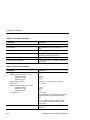
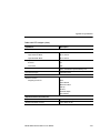
General Safety Summary
Review the following safety precautions to avoid injury and
prevent damage to this product or any products connected to it.
Only qualified personnel should perform service procedures.
To avoid potential hazards, use this product only as specified.
Injury Precautions
Use Proper Power Cord
To avoid fire hazard, use only the power cord specified for this
product.
Avoid Electric Overload
To avoid electric shock or fire hazard, do not apply a voltage to a
terminal that is outside the range specified for that terminal.
Avoid Electric Shock
To avoid injury or loss of life, do not connect or disconnect probes
or test leads while they are connected to a voltage source.
Ground the Product
This product is grounded through the grounding conductor of the
power cord. To avoid electric shock, the grounding conductor must
be connected to earth ground. Before making connections to the
input or output terminals of the product, ensure that the product is
properly grounded.
Do Not Operate Without
Covers
Use Proper Fuse
To avoid electric shock or fire hazard, do not operate this product
with covers or panels removed.
To avoid fire hazard, use only the fuse type and rating specified for
this product.
AM700 Audio Measurement Set User Manual
xiii
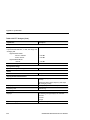
General Safety Summary
Do Not Operate in
Wet/Damp Conditions
Do Not Operate in
Explosive Atmosphere
To avoid electric shock, do not operate this product in wet or damp
conditions.
To avoid injury or fire hazard, do not operate this product in an
explosive atmosphere.
Product Damage Precautions
Use Proper Power Source
Use Proper Voltage
Setting
Provide Proper
Ventilation
Do Not Operate With
Suspected Failures
Do not operate this product from a power source that applies more
than the voltage specified.
Before applying power, ensure that the line selector is in the proper
position for the power source being used.
To prevent product overheating, provide proper ventilation.
If you suspect there is damage to this product, have it inspected by
qualified service personnel.
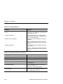
Safety Terms and Symbols
Terms in This Manual
These terms may appear in this manual:
WARNING. Warning statements identify conditions or practices that
could result in injury or loss of life.
xiv
AM700 Audio Measurement Set User Manual
General Safety Summary
CAUTION. Caution statements identify conditions or practices that
could result in damage to this product or other property.
Terms on the Product
These terms may appear on the product:
DANGER indicates an injury hazard immediately accessible as
you read the marking.
WARNING indicates an injury hazard not immediately accessible
as you read the marking.
CAUTION indicates a hazard to property including the product.
Symbols on the Product
The following symbols may appear on the product:
DANGER
High Voltage
Protective Ground
(Earth) Terminal
ATTENTION
Refer to
Manual
Static-Sensitive
Devices
Certifications and Compliances
CSA Certified Power
Cords
Compliances
CSA Certification includes the products and power cords
appropriate for use in the North America power network. All other
power cords supplied are approved for the country of use.
Consult the product specifications for IEC Installation Category,
Pollution Degree, and Safety Class.
AM700 Audio Measurement Set User Manual
xv
General Safety Summary
xvi
AM700 Audio Measurement Set User Manual
Introduction and Installation
Introduction and Installation
The Tektronix AM700 Audio Measurement System is a programmable, highperformance, mixed signal audio analyzer designed for use in product design,
characterization, quality control, manufacturing test, and servicing. The AM700 is
also a valuable tool for monitoring and testing of signal distribution systems used in
broadcasting and related applications.
The AM700 Audio Measurement System is an audio test set combining the signal
generating capability of a two-channel analog and digital audio generator with the
measurement and analysis capability of a two-channel analog and digital audio
analyzer. Extensive use of digital signal processing provides this mixture of
advanced capabilities.
All hardware control, instrument configuration, data storage and I/O operations can
be accomplished with the front-panel interface. The AM700 can be operated
remotely through its GPIB port. Timed functions can be programmed using remote
control.
Key Features of the AM700
H
The AM700 is compact, light weight, and self contained making it suitable for
both bench and portable audio testing applications.
H
The AM700 is the first advanced audio analyzer to employ the proven
touch/turn/zoom interface consisting of hard keys, knobs, and touch screen soft
key controls.
H
Graphical and text displays of measurements are viewed on a flat-panel LCD
color display. A touch screen and soft key menu structure provides the user
interface to the extensive applications of the AM700. Larger, external color
displays of the AM700 screens are supported with a VGA port and usersupplied VGA monitor.
H
Printed copies of screens of the AM700 can be output to printers connected to
RS-232C or GPIB ports. In addition, you can store the information on a
1.44 Mbyte, 3.5-inch floppy disk, using the internal disk drive, for later use or
analysis.
AM700 Audio Measurement Set User Manual
1-1
Introduction and Installation
H
The SOUND function in all applications (except Digital Interface Tester) allows
monitoring of signals through headphones.
H
The physical size of the AM700 is approximately 7.7 inches high, 18.2 inches
wide (with handle), 18.8 inches deep, and it weighs about 31 pounds. This size
allows the instrument to fit laboratory bench space and enhances portability.
The standard accessory front cover provides extra protection to the face of the
AM700 when used as a portable instrument or when stored. The AM700 can
also be rackmounted in a standard 19-inch rack using the optional rackmounting
accessory kit.
Operation and Controls
The flat-panel display face is overlaid with a touch screen that is used for selection
of many of the operating parameters. Screen areas are firmware defined for touch
control of the various application menus and configuration screens used to control
the operation of the AM700. Touches to the screen are indicated by a click when an
active area has been selected. Touches outside an active area produce no sound.
Viewing parallax of the control zones cam cause you to touch in the wrong area
when the zones are close together. If the touch screen control zones become
misaligned with the underlying display, you should do a touch screen calibration.
NOTE. A small blunt-pointed tool, such as the top of a pen or pencil eraser may be of
help in touching the correct zone. A light press is all that is needed to record the
touch. Touches to the screen are queued and multiple actions will occur if you touch
the screen several times in succession without waiting for the first requested action
to occur.
Most operating modes are accessible by a single front-panel button. More features
are accessed with short combinations of front-panel buttons and soft key selections
that appear on menus in the display viewing area. Menu selections are made by
pressing the touch screen in the menu selection area. Front-panel knobs control the
internal audio generator and zoom/position function.
The color LCD display of the AM700 produces sharp, clear images. Displays are
designed to provide a great deal of graphical measurement information yet eliminate
1-2
AM700 Audio Measurement Set User Manual
Introduction and Installation
a cluttered viewing area. The display screens can be formatted for any external
PostScript, Laserjet, or Epson-compatible printer for generating printed copies of
the measurements and waveforms. Graphic images in PostScript and TIFF formats
can be formatted for color copy.
The AM700 has a unique view window feature that lets you view multiple graphical
measurement displays. Use this feature to make distortion, phase, or crosstalk
measurements while still viewing a critical signal parameter, such as signal level.
Measurement Capability
Analog and digital signal applications include Audio Analyzer, FFT Analyzer with
multitone capabilities, and an Audio Monitor. You cam apply analog signals to one
measurement channel and digital signals to the other measurement channel and
simultaneously make measurements on both.
Features of the Digital Interface Tester include an Eye Height display, a Bit Activity
display, Jitter and Sample Rate measurements, and a decoded Channel Status
display. Extensive monitoring and measurement capability on a variety of digital
audio signals are standard.
With the AM700 you can perform several related measurement or monitoring tasks
at once.
Audio Signal Generator Capabilities
The AM700 includes signal generating capability allowing users to create test
signals in Analog and Digital Audio domains. These generators can be operated in
concert with the analyzer function or as a stand-alone test signal source. The analog
and digital generators can also be used either simultaneously or independently.
The analog generator has a great deal of operation flexibility. Its balanced output
signals can be referred to either chassis ground or floating. The analog signal
generator can produce different signals on each of its pair of output channels. In
addition, a front-panel selected internal connection permits the output of the
generator to be directly connected to the analog and digital inputs without the need
for external cabling when checking out the operation of the AM700.
AM700 Audio Measurement Set User Manual
1-3
Introduction and Installation
The digital generator is also very flexible. It can produce test signals in AES/EBU,
SPDIF, Optical, and raw data forms at a variety of sample rates. Like the analog
generator, it can produce independent signals on either channel. In addition to the
audio test signals, you can use this generator to manipulate the Channel Status Data
and User Data bits in the serial data stream. Varying types and degrees of corruption
can be added to the output to permit testing of devices under real-world conditions.
When the Audio Analyzer application is in use, the internal generator sweeps can be
driven in a closed-loop mode of operation. This mode is very useful for stimulating
a device under test and waiting for the Analyzer to acquire the signal output from
the device under test before stepping to the next step in the sweep. Propogation
delays through the device under test and the settling time needed to produce a stable
signal are accounted for by the Settling Detection feature so that, if possible, settled
data is acquired at each step before advancing to the next step.
Installation of the AM700
This information includes the power requirements, power cord information, and fuse
information for installing the AM700. Calibrating the touch screen and setting the
real time clock are also included here as part of the initial start-up routine after
installation.
Power
Requirements
The AM700 operates with line frequencies of 50 Hz or 60 Hz over two line voltage
ranges. The nominal setting of the low voltage range is 115 VAC. The nominal
setting of the high voltage range is 230 VAC. The AM700 power requirement is
185 watts or 230 volt-amperes at maximum power consumption.
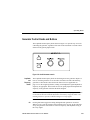
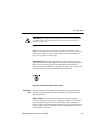
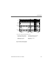
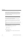
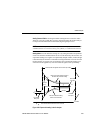
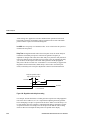
There are two power switches on the AM700. They are the main power switch, a
push button switch on the rear panel above the power cord receptacle (see
Figure 1-1), and the Stby/On button on the front panel. Both must be on to operate
the instrument.
WARNING. Dangerous voltages are present within the Power Supply module when
the rear-panel power switch is on, regardless of the position of the front-panel power
switch. Do not operate the AM700 with any covers removed. Refer all servicing of
the instrument to a qualified service person.
1-4
AM700 Audio Measurement Set User Manual
Introduction and Installation
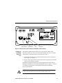
Power connector
On/Off switch
Fuse
Line selector
Figure 1-1: Rear panel fuse, power connector, On/Off Switch, and line selector
Changing the
Line Voltage
Range and
Fuse
The AM700 is shipped from the factory set for the operating voltage of the
destination country (115 VAC or 230 VAC). If the setting is not correct, it must be
changed before connecting the power cord to the power source.
1.
Turn off the rear-panel power switch and disconnect the power cord from the
mains supply (see Figure 1-1).
2.
Set the voltage range selection switch (located on the rear panel of the AM700)
to the correct position for operation.
Instruments are shipped with the power cord most appropriate for the country of
destination. Available power-cord option information is given in Table 1-1. Contact
your Tektronix representative or local Tektronix field office for additional
power-cord information.
CAUTION. When changing the line voltage selector switch you must also change
the fuse to provide proper protection for the operating voltage in use.
AM700 Audio Measurement Set User Manual
1-5
Introduction and Installation
The mains fuse provides protection in the event of a major failure of the AM700
power supply. Two sizes of fuses are specified, one for 115 V operation and the
other for 230 V operation. Refer to Fuse Rating on page A-27 of Appendix A for the
correct fuse rating to use for each voltage range.
3.
Replace the fuse with the correct one, as indicated on the rear panel, for the
new mains voltage selection.
CAUTION. Use only the power cord and connector specified for your product. Use
only a power cord that is in good condition with a proper safety ground connector.
4.
Replace the power cord with the correct one for use with the local mains
outlets.
5.
Turn on the rear power switch. Then turn on the front power switch to operate
the AM700.
Power Cord
A detachable three-wire power cord with a three-contact plug is provided with each
instrument for connecting to both the power source and protective ground. The
protective-ground connector in the plug connects (through the protective-ground
conductor) to the accessible metal parts of the instrument. For electrical-shock
protection, insert this plug only into a power-source outlet that has a properly
grounded protective-ground contact. The voltage to ground from either pole of the
power source must not exceed 250 VRMS. For electric-shock protection, the
grounding connection must be made before making connections to the instrument
input or output terminals.
Power Up
Procedure
At power up the AM700 normally bypasses the power-up diagnostics and starts the
FFT application. You can start an application other than FFT by pressing and
holding in the front-panel button for the application you want to start as you turn on
the front panel power switch. The AM700 will beep twice, and you can then release
the application front-panel button. To run the power-up diagnostics, press and hold
in the front-panel Limits button as you press the front-panel power button. The
AM700 beeps twice, displays the message ‘Start mode “RUN DIAGNOSTICS”
recognized,’ and then runs the diagnostics before initialization.
1-6
AM700 Audio Measurement Set User Manual
Introduction and Installation
Should a power-up diagnostic fail, the AM700 should be referred to your local
Tektronix representative for servicing. Should the AM700 go into a continuous reset
condition, refer to Appendix A of the AM700 Programmer Manual for the procedure
used to clear the NVRAM of possible undefined states.
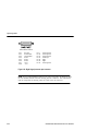
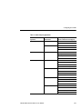
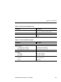
Table 1-1: Optional Power Cords
Power Plugs
Description
Standard
North American
120 V plug
Reference Standards1
ANSI C73.11
NEMA 5-15-P
IEC 83
UL 198.6
Option A1
Universal Euro
220 V plug
CEE(7)
II, IV, VII
IEC 83
IEC 127
Option A22
United Kingdom
240 V plug
BS 1363
IEC 83
IEC 127
Option A3
Australian
240 V plug
AS C112
IEC 127
Option A5
Switzerland
220 V plug
SEV
IEC 127
1Reference Standards Abbreviations:
ANSI—American National Standards Institute
AS—Standards Association of Australia
BS—British Standards Institution
CEE—International Commission on Rules for the Approval of Electrical Equipment
IEC—International Electrotechnical Commission
NEMA—National Electrical Manufacturer’s Association
SEV—Schwetzervischer Elektrotechischer Versin
UL—Underwriters Laboratories Inc.
2A 6 A, type C fuse is also installed inside the plug of the Option A2 power cord.
AM700 Audio Measurement Set User Manual
1-7
Introduction and Installation
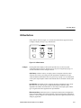
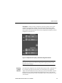
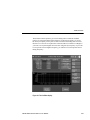
Calibrating
the Touch
Screen
The AM700 is shipped from the factory with its touch screen fully calibrated.
Although it will seldom be necessary, the touch screen can easily be recalibrated.
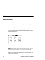
To calibrate the touch screen:
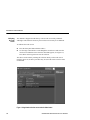
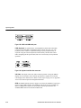
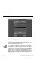
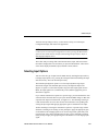
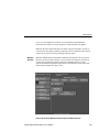
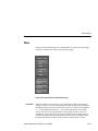
H
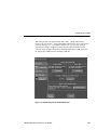
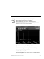
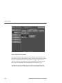
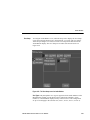
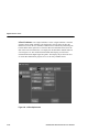
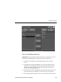
Press the front-panel button labeled “Other.”
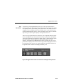
H
Use the large control knob to scroll through the menu choices and select the
touch screen calibration choice from the menu that appears (see Figure 1-2).
Press Enter on the keypad to activate the selection.
The choice can be made by touching the selection directly on the touch screen
interface. However, the above procedure may be used if the touch screen becomes
uncalibrated.
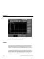
Figure 1-2: Application selection menu under the Other button
1-8
AM700 Audio Measurement Set User Manual
Introduction and Installation
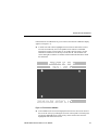
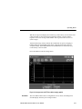
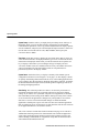
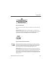
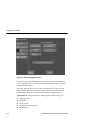
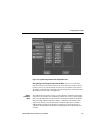
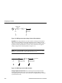
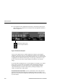
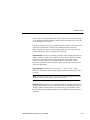
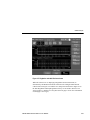
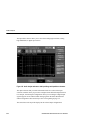
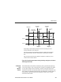
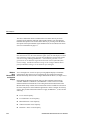
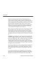
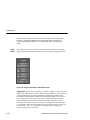
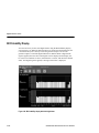
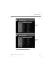
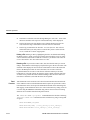
Full instructions for calibration are given on the screen when the calibration display
appears (see Figure 1-3).
H
A small circle with a dot is highlighted in succession in each of three corners.
View the screen directly on to avoid parallax errors and use a small blunt
pointed tool, such as a pencil eraser tip, to produce the best accuracy for the
calibration. Touch the screen directly over the first dot. The dot in the next
corner then lights. Touch the second dot, and then touch the third dot to finish
the calibration.
Figure 1-3: Touch screen calibration
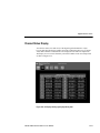
H
After calibration, the screen will display the Paint screen. You can test areas of
the screen for activity by touching the screen at various points. The touch point
will become highlighted. The Clear soft key on the touch screen erases the
highlighted areas of the Paint screen.
AM700 Audio Measurement Set User Manual
1-9
Introduction and Installation
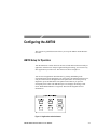
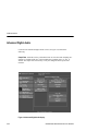
H
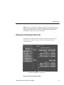
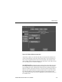
Setting the
AM700 Clock
Press any application front-panel button to exit the paint screen and start the
application.
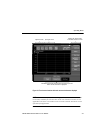
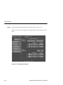
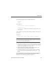
The AM700 has a system clock with an internal backup battery. After setting for
your local time, it is ready to use. Performing this exercise for the first time will also
introduce you to the Configure menus that you will use as you set up the AM700. To
set the clock use the following procedure:
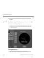
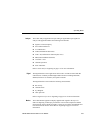
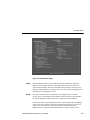
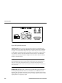
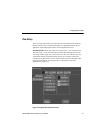
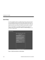
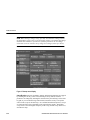
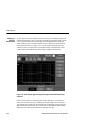
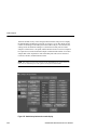
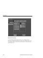
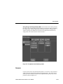
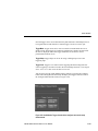
1.
Press the Configure button on the front panel. This displays the choices for
configuring the various user selections of the AM700. Clock setting is done in
the System Setup option.
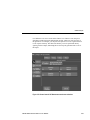
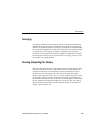
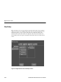
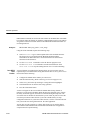
Figure 1-4: AM700 System Clock
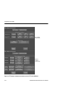
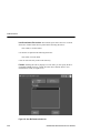
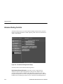
2.
1-10
Touch “System Setup” to display the choices under that option. Clock is the
default selection, and the clock face appears as seen in Figure 1-4.
AM700 Audio Measurement Set User Manual
Introduction and Installation
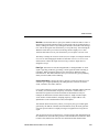
3.
Check the date and time settings. If any are not correct, select them individually
to adjust to the correct setting. A selected choice changes intensity to show that
editing of that setting is active.
4.
Set the correct number by rotating the large control knob or by entering the
correct number with a direct keypad entry and pressing the Enter button.
Changes made to the time are shown in the clock as they are entered, but those
changes are not permanent until the Accept Changes soft key is touched.
5.
When the date and time are correct, touch the Accept Changes soft key. This
changes the time to the new values and returns to the previous application.
CAUTION. The backup battery used to retain stored data has an operating life of
greater than 10 years when operating between 0d and 50d C. If operating out of that
range for extended periods of time, the battery life can be reduced or stored data
can be lost.
Internal
Backup
Battery
The nonvolatile memory of the AM700 is held by an internal backup battery. Stored
data will be retained for the life of the battery. A fresh battery installed at the factory
has a life of greater than 10 years when operated and stored at an ambient
temperature between 0d and 50d C. Battery life can be reduced if the AM700 is
stored for an extended time above 50d C, and retained data can be lost if the AM700
is stored for extended periods below 0d C.
Options
The following options are available for use with the AM700:
H
Options A1 through A5 substitute an appropriate power cord for the country of
use (see Table 1-1).
H
Remedial Service Support
Option M2
H
Repair Protection
Option M9
AM700 Audio Measurement Set User Manual
1-11
Introduction and Installation
Standard Accessories
H
AM700 User Manual
H
AM700 Programmer Manual
H
AM700 Programmer Quick Reference Manual
H
Standard power cord (optional power cord substituted when ordered)
H
Front Cover
Optional Accessories
Accessories can be used for remote control, signal interfacing, and rackmounting.
The following optional accessories are available:
H
GPIB Cable: double shielded in various lengths
H
1 meter
Tektronix part number 012-0991-01
H
2 meter
Tektronix part number 012-0991-00
H
4 meter
Tektronix part number 012-0991-02
H
Tektronix ASW 100F Input Signal Switcher
H
Tektronix ASW 100M Output Signal Switcher
H
Rackmounting kit
Tektronix part number AM7FR1
H
External keyboard
Tektronix part number 119-4254-01
User-supplied Accessories
1-12
H
Standard VGA monitor (connect to the VGA Video output connector for
viewing the AM700 color display on an external monitor)
H
Ariel digital microphone (for direct audio input to the DSP input port)
H
XLR interconnection audio cables
H
BNC to XLR adapters
H
RCA Phone to XLR adapters
H
AT-compatible keyboard with 6-pin, mini-DIN connector (in lieu of Tektronix
part numbered optional accessory)
AM700 Audio Measurement Set User Manual
Operating Basics
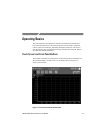
Operating Basics
This section describes the AM700 user interface and connections and introduces
basic instrument operations. Topics discussed in this section include: front-panel
controls, touch-screen interface, and analog and digital connections. This section
also describes the basic operations that must be performed while using the AM700
for audio measurement and analysis.
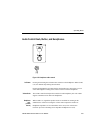
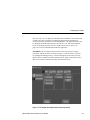
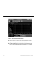
Touch Screen and Front Panel Buttons
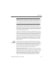
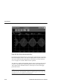
The AM700 is controlled by selecting from measurement parameters and menus on
the instrument display. A touch screen over the display (shown in Figure 2-1)
detects your selections.
Figure 2-1: Touch screen interface without menus
AM700 Audio Measurement Set User Manual
2-1
Operating Basics
Many AM700 operations are started by selecting soft keys (shown in Figure 2-2)
using the touch screen (touching the display in the right place to invoke some
function). In some menus, numerical values are entered either from the keypad or
with the control knob.
Front panel buttons with gold outlines (Copy, Average, Cursor, Sound, Filter, Sound
On, User, and Units) have two possible behaviors, depending on how you use them
and the application or display that is running. If you press a button that is not used
by an application, no action occurs.1
1.
When pressed and immediately released, each of the gold-outlined buttons
performs a default action (turning on or off the specified feature).
2.
When any of the gold-outlined buttons is pressed and held for one second or
more, a configuration menu related to its operation is displayed.
NOTE. The button default action (selected when you press and release the frontpanel button) does not occur when exiting a press/hold menu. Instead, you must
again press and release the button to perform the default action.
The LEDs associated with these buttons track the action you select, not the
configuration menu associated with the hard key. For example, the Filter hard key
LED lights only when you select filtering.
During operation of the AM700 the following objects can appear in the display:
H
One to four measurement view windows
H
Generator Status area
H
Generator Control Panel
H
Menu and Soft Keys selections
H
Operational status and Real Time measurement displays
H
Notifier messages
1An example is the Filter menu. Filters are only available in Audio Analyzer, so when the Digital Interface Tester
or the FFT analyzer is running, pressing the Filter button has no effect.
2-2
AM700 Audio Measurement Set User Manual
Operating Basics
Application name
Input signal source
Submenu bar appears when
a Main Menu selection is made.
Main Menus appear when the front-panel menu button is pressed.
When selected, the button is highlighted.
Figure 2-2: Touch screen interface with main menus and submenus displayed
NOTE. When menus or soft key selections are grayed out, it means those choices are
not currently available for selection. This will be seen when the selections are not
applicable to the active view window or the selections cannot be used in the current
operation of an application.
AM700 Audio Measurement Set User Manual
2-3
Operating Basics
Application
Control
An AM700 application is started by pressing a button (if it has a dedicated
front-panel button) or by selecting it from the menu displayed when the “Other”
front-panel button is pressed and released.
Each AM700 measurement application corresponds functionally to a dedicated
measurement instrument. The AM700 runs one measurement application at a time.
The Generator is independent of the application and maintains its settings between
applications.
Display Icons
The AM700 uses icons in its menus and control panels to represent actions or
available choices. Some of these icons are displayed in Figure 2-3. The display view
selections icons are application specific and are introduced in the Applications
section of this manual beginning on page 4-1.
Views
Figure 2-4 shows the Views selection bar displayed at the top of the FFT Analyzer
application. Touching a Views icon toggles the display of that view on and off. Each
selected view is size adjusted to accommodate all the views you request in the
display.2 In the most applications, the four views can be displayed as one to four
windows in any combination with a selection of measurements possible in each
view. In FFT Analyzer, the four views are initially set up with views 1 and 2 as FFT
measurements and views 3 and 4 as multitone measurement, but you can change this
set up.
2 An exception to this is seen in the Digital Interface Tester. In that application each view is a different measurement
that cannot be made with the other measurements running. In that application only one measurement view window at
a time is displayed.
2-4
AM700 Audio Measurement Set User Manual
Operating Basics
DISPLAY VIEW
GENERATOR STATUS READOUT
REAL TIME MEASUREMENTS
TWO OR MORE CHOICES ARE TOGGLED
A LIST OF CHOICES IS AVAILABLE
CHOICE IS SELECTED
CHOICE IS NOT SELECTED
SELECTION IS ENABLED
SELECTION IS NOT ENABLED
MOVE OR EXPAND HORIZONTALLY
MOVE OR EXPAND VERTICALLY
HORIZONTAL ZOOM POINT
VERTICAL ZOOM POINT
LARGE CONTROL KNOB
GENERATOR KNOBS ASSIGNED
Figure 2-3: Representative icons and arrows seen in the AM700 display
AM700 Audio Measurement Set User Manual
2-5
Operating Basics
Figure 2-4: Views selection bar with only View 1 selected for display
When multiple view windows are displayed (including the RT and Generator Status
views), assigning the controls to a particular view is done by touching the screen in
that view. The touched view then becomes the active view and is indicated by a
brighter border around that view window as shown in Figure 2-5. Cursor controls
and the move/expand action are directed to the traces in the active view.
You can set each view to display a different measurement or combinations of
measurements. For example, in the Audio Analyzer, view 1 can be set to display
Channel 1 frequency versus Channel 1 level, view 2 can be of Channel 1 level
versus Channel 1 THD, view 3 can be of Channel 1 level versus Channel 2 level,
and view 4 can be of Channel 2 level versus Channel 2 THD. The choice of
measurement channel and measurement type assigned to an axis in the graphical
views is flexible. Refer to View Setup on page 3-7 for more information on setting
up the views and selecting the measurement traces for the views.
Graphical
Display Types
2-6
The AM700 offers several choices for displaying data in a view window. Where
applicable, the following display types are possible.
H
Point-to-point plots of measurement results (traces)
H
Traditional Y-Axis versus X-Axis waveform display
H
Table of data (updating as new data is acquired)
H
Spectrogram
H
Eye diagram
H
Histogram
AM700 Audio Measurement Set User Manual
Operating Basics
Real-Time
Readout view
window
Bright border indicates the view
window that has the control focus.
Generator Status
view window
Figure 2-5: View windows and control assignment
Measurement
Units
You can also select the units in which the data is displayed. These unit selections
apply to measurement readouts, parameter settings, and graphical display axes.
Where appropriate, the following units choices are available.
H
Hz, kHz
H
V, V, mV, mV
H
dB, dBu, dBV, dBr, dBFS
H
dBm
H
%
H
S, mS
AM700 Audio Measurement Set User Manual
2-7
Operating Basics
Front-panel Operation
The AM700 front panel consists of a touch screen, selections buttons and control
knobs divided into functional control areas, and a numeric keypad. Figure 2-6
illustrates the front panel of the AM700.
Figure 2-6: AM700 front panel
Front Panel
Button
General
Information
2-8
Many of the front panel button labels have back lights. These back lights are on to
light up a button label when the selection for that button is active. Other front-panel
button labels have a gold outline. The buttons with gold-outlined labels have two
operations; the first is to turn on and off the selection indicated by the button label.
This action occurs with a quick press and release of the button. The second action is
to display a menu for setting user-selectable settings for the associated action or to
provide additional control selections. The menu associated with a gold-outlined
button is reached by pressing and holding the button until the menu is displayed.
AM700 Audio Measurement Set User Manual
Operating Basics
System Control Buttons
The System Control buttons shown in Figure 2-7 provide control of function that are
not application specific. In general the system functions are available for use with
all the applications.
Figure 2-7: System control buttons
Menu
Pressing the Menu button displays the soft key controls that are available for the
application currently in use.
Limits
The Limits feature of the AM700 has not been activated.
Rescale
Pressing the Rescale button adjusts the vertical and horizontal resolution for
optimum display of the measured data. The Rescale button has two actions. Press
and quickly release the button to rescale only on the plotted data points in the view
that has been selected by touching it. Press and hold the Rescale button to rescale all
views.
AM700 Audio Measurement Set User Manual
2-9
Operating Basics
Freeze
Pressing the Freeze button (a toggle) halts display updates. Some frozen displays
cam be expanded horizontally and vertically. When expanding a frozen display, the
AM700 interpolates acquired data to provide display points for the expanded
displays. Also, cursors can be used on the frozen display to make measurements.
Display updates are resumed when Freeze is pressed a second time.
Filter
A selection of input filters is available in AM700 firmware for use with the Audio
Analyzer. Other types of filter are available from within applications that require
specific filtering to obtain the measurement. Refer to Input Filtering on page 4-75
for information on filter types and operation.
When the Audio Analyzer application is running, pressing the Filter button (a
toggle) applies the selected filter to the measurement data. You can select from a
menu of available filters by pressing and holding the Filter button to display the
choices available for Channel 1 and Channel 2. To access the choices, the Filter
front-panel button must be lighted (Filter on).
Cursors
Pressing the Cursors front-panel button places two cursors on the display and lets
you position them to mark display features. The numerical display shows frequency
and level at each cursor location and the timing difference between the two cursors.
Cursors can be used to select measurement points in a waveform. Cursor position is
adjusted using the Control Knob with cursor positioning active. The cursors can be
used to provide a continuous readout of the amplitude and frequency at the cursor
position. The active cursor position is also the expansion point when horizontal
expand (Zoom) is enabled.
The difference readouts (both amplitude and time or frequency) shown in the view
window above the graticule are based on the position of cursor 1 (the solid cursor)
minus the position of cursor 2 (the dashed cursor).
NOTE. When cursors are visible in the display window, cursor position is shown
above each cursor. When cursors are positioned beyond the display window, cursor
position is shown in either upper corner of the display with an arrow pointing
toward the cursor.
2-10
AM700 Audio Measurement Set User Manual
Operating Basics
Pressing and holding the Cursor button brings up the Cursor menu as shown in
Figure 2-8. The menu controls permit you to select cursors and employ some special
positioning actions.
Figure 2-8: Cursor menu showing frequency and level readouts
Next Cursor. Next Cursor toggles the active cursor selection between the two cursors.
Cursor 1 is indicated as a solid vertical line; cursor 2 is indicated as a dashed
vertical line. The active cursor is brightened. You can position the active cursor by
rotating the large control knob or by touching it and dragging it to a new position.
Join Cursors. Join Cursors moves the two cursors together so that the starting
positions of the cursor can be quickly set. If one cursor is active, the other will move
to meet it. If neither is selected, they will both be centered in the display. You will
typically use this selection when first bringing up the cursors to help you find them
since it places both cursors together.
AM700 Audio Measurement Set User Manual
2-11
Operating Basics
Snap to Data. Snap to Data, when enabled, causes the cursors to be positioned from
data point to data point (not interpolated points) in the trace. When not enabled,
cursors are not held to the acquired data points and they are positioned smoothly
along the trace.
Next Peak and Previous Peak. The Next Peak and Previous Peak soft keys are
available with either cursor active. Next Peak moves the active cursor on the nearest
signal peak to the right of the cursor while showing the frequency and signal level of
the peak in the numerical display. The cursor does not automatically go to the
highest peak; it goes to the next closest peak.
NOTE. In the FFT application, the “finding the peak” functions can miss some peaks
if the Uniform window is in use (refer to Uniform on page 4-82).
Previous Peak. Previous Peak moves the active cursor to the nearest signal peak to
the left of the cursor. The frequency and signal level of the peak is displayed in the
numerical display.
Press the Clear Menu button to exit the cursor menu.
Averaging
An Average feature is available for use with measurements in the FFT Analyzer and
the Jitter Spectrum function in the Digital Interface Tester. Pressing and releasing
the Average button turns Averaging on and off in applications that can use
averaging. Pressing the Average button when the feature is not available for use has
no effect. Averaging is used to remove random noise from the display trace so that
small amplitude frequency components are easily observed.
To turn on averaging for a trace, first touch the view that contains the trace you want
to average. As indicted by the gold-outlined label, the Average button has two
operations: pressing and releasing turns averaging on or off for the selected view;
pressing and holding the Average button brings up the Average menu as shown in
Figure 2-9. You can select the number of acquisitions to be averaged either using the
control knob or by making a keyboard entry with the Averaging menu number
selection active. Other choices in the averaging menu are Holding Minimum and
Holding Maximum.
2-12
AM700 Audio Measurement Set User Manual
Operating Basics
With the Average menu displayed, touch the Avg Count soft key to activate the field
editor and either use the control knob to adjust the number or use the numeric
keypad to enter a new average count number. The Avg Count can be set for 1 to
9,999 averages.
Touch the Processing soft key and turn the control knob to specify averaging or
holding minimum or maximum signal values. Touch the Processing soft key to
accept the change. With Hold Maximum or Hold Minimum is selected, the Avg
Count soft key is not accessible.
Press Clear Menu to exit the Average menu.
Figure 2-9: Average menu and FFT trace with averaging applied
Clear Menu
The Clear Menu button removes configuration screens, menus, and dialog boxes
from the display when they are no longer needed.
AM700 Audio Measurement Set User Manual
2-13
Operating Basics
Applications Buttons
The AM700 applications are introduced here. Refer to Applications beginning on
page 4-1 for detailed information on each application. Operation of the generator is
included in the applications information, followed by the Analyzer, FFT, Digital,
Monitor, and Functions, in that order.
The buttons in the Applications area control, shown in Figure 2-10, provide access
to AM700 measurement applications. You can start an application by pressing its
button. You can also start applications by pressing the Other button, turning the
knob to select an application, and touching the Run Application soft key. This
means of accessing an application is also available for accessing diagnostics and the
touch-panel calibration routine.
Figure 2-10: Applications buttons
NOTE. Press the Clear Menu button to exit the Select Application screen (displayed
when you press the Other button) and cancel any changes you may have made.
Requesting a new application causes the AM700 to stop the current application and
replace it with the new application.
2-14
AM700 Audio Measurement Set User Manual
Operating Basics
Analyzer
The Audio Analyzer application accepts analog or digital audio input signals for
analysis. This application makes the following measurements:
H
Signal Level and Frequency
H
Stereo Phase Difference
H
Level Difference
H
THD (total harmonic distortion)
H
THD + N (total harmonic distortion plus noise)
H
IMD (intermodulation distortion)
H
Crosstalk + noise
H
Channel separation
H
Wow and Flutter
Refer to Audio Analyzer beginning on page 4-37 for more information.
Digital
The Digital Interface Tester application can be used to evaluate electrical and data
characteristics of industry standard digital audio interfaces including AES/EBU,
SPDIF (also known as consumer), and optical consumer.
The Digital Interface Tester makes the following measurements:
H
Bit Activity
H
Channel Status
H
Eye Diagram
H
Jitter Spectrum
Refer to Digital Interface Tester beginning on page 4-107 for more information.
Monitor
The Audio Monitor application displays applied audio signals in the style of a
dual-trace digitizing oscilloscope presentation. You can make simple time-domain
measurements on these displayed signals. Cursors are provided to aid amplitude and
time measurements. Refer to Audio Monitor beginning on page 4-97 for more
information.
AM700 Audio Measurement Set User Manual
2-15
Operating Basics
FFT Analyzer
The FFT Analyzer has both FFT Measurement and Multitone Measurement
applications.
FFT Measurements. The FFT Analyzer can display two channels simultaneously.
These displays can either be on separate frequency and amplitude axes or overlaid
onto the same frequency and amplitude axes. Using any combination of analog and
digital inputs set up in the Configure menu, the FFT Analyzer produces displays of
frequency domain data much like those of a spectrum analyzer. The span (bandwidth of the FFT display) can be zoomed (expanded or contracted horizontally) and
panned (scrolled left or right through the display).
Multitone Measurements. The multitone mode of the FFT Analyzer uses short
duration test signals composed of multiple tones spread across the audio spectrum to
measure a wide variety of audio system parameters. Differences between known test
signals and the acquired response from the system under test can be rapidly
analyzed to determine frequency response, distortion and noise, and channel
separation. Multitone measurements can be made on any combination of analog or
digital input signals.
Refer to FFT Analyzer beginning on page 4-81 for further information.
Other
All applications including the diagnostics and touch screen calibration are accessible
through the menu displayed when you press the Other button.
User
The User button has two actions, as indicated by the gold-outlined label. Press and
quickly release the User button to run the application or function you have assigned
to the User button. Press and hold the User button to display the User menu. This
screen displays the available AM700 applications and functions. You can select one
of these to be run when the User button is pressed.
To assign an application or function to the User button, touch the Show Applications
or Show Functions soft key as appropriate to select an application or function. Turn
the control knob to select the application or function you want to assign to the User
button, touch the Set User soft key, and exit the screen by pressing the Clear Menu
button. Now, when you press the User button, the assigned function or application
will run.
2-16
AM700 Audio Measurement Set User Manual
Operating Basics
Utilities Buttons
Utility buttons, shown in Figure 2-11, activate and control these support functions:
Configure, Display, Storage, Copy, and Function.
Figure 2-11: Utilities buttons
Configure
Pressing this button displays soft keys that provide access to various system
configuration menus. Refer to AM700 Setup for Operation beginning on page 3-1
for more information on the configure choices.
Quick Setup. Touch this soft key to display a menu of template selections. These
selections save time by providing one-touch instrument configuration for some
common AM700 measurements. Refer to Quick Setup on page 3-22 for information
on the quick setup templates and the measurements that are available with the quick
setups.
Input Selection. Touch this soft key to display the Input Configuration menu. From
this menu you can select the type of input and front panel connection, input
impedance and whether the instrument is to auto range on the input signal, and the
type of signal source that is applied to the input channels.
Measurement Setup. Touch this soft key to display the Measurement Configuration
menu. From this display other soft keys display various measurement configuration
options in various categories. The contents of the menus are application specific and
change by application.
AM700 Audio Measurement Set User Manual
2-17
Operating Basics
System Setup. Touch this soft key to display the System Setup menu. Soft keys in
this display allow you to set the date and time, configure the serial and GPIB
communications parameters, select copy format and destination for display captures,
activate calibration, and specify the external input and output resistance values to be
used for units conversions between volts, dBu, and dBm, and to specify the
conversion factor to dBFS.
View Setup. Touch this soft key to display the View Setup menu. Here is where you
select the measurements to be displayed and the type of view in which the selected
measurement is displayed. In this menu you can also touch the View Options soft
key to display a menu where you can configure the type of display axes and
waveform, whether cursors are enabled (turned on or not), and whether the cursors
will be constrained to the trace data (Snap to Data) or will permitted to be
positioned anywhere in the display window.
System Status. Touch this soft key to display a summary of the AM700 system
configuration selections as seen in Figure 2-12 on page 2-19. This display is useful
for quickly determining what measurement the views in the running application are
set up to display, how the trace data is displayed (interpolator, point plot, or tabular),
the measurement channel input selection, and the generator signal type choices for
the analog and digital generators.
State Saving. This selection provides two choices: one saves the present state of
instrument settings that can be saved, and the other restores the factory default
settings. If you want to save a particular setup state for an application, it should be
done immediately before turning off the AM700. Settings for many of the controls
are saved each time an application is changed. Any settings that are saved when
State Save is used are overwritten if further changes are made and another
application is started prior to power off. State Save does not return the application
that was running at power off when power is again turned on, but the user selections
for an application that were saved will be restored.
Also, refer to the Save AM700 State function discussion on page 4-136. The Save
AM700 State function generates new functions that store customized application
setups. These application setup functions are then used in making repetitive tests
and for building a standardized set of application setups that can be transferred to
other AM700 Audio Measurement Sets.
2-18
AM700 Audio Measurement Set User Manual
Operating Basics
Figure 2-12: System Status display
Display
When the Display button is pressed and held, the large control knob adjusts the
display intensity. Display intensity values range from about 10% for full dim to
100% for full brightness. The power on default setting for display intensity is 90%.
When the display brightness is reduced to 40% or lower, pressing the Display button
immediately sets the brightness to 90%.
Storage
Files can be transferred between the DOS system (floppy-disk drive) and the
memory system of the AM700. In the AM700, the files are those stored in ROM at
the time of shipment and those that are user created and stored in NVRAM.
File transfers and moving through the directories is done using the Storage Manager
control screen that is called up when the front-panel Storage button is pressed (see
Figure 2-13). This feature is of primary importance for using the Function
application as it is currently implemented and in the creation of other user files.
AM700 Audio Measurement Set User Manual
2-19
Operating Basics
Function files and user files written on an external PC can be downloaded to the
appropriate NVRAM directory for use.
The Storage Manager detects the presence of a floppy disk in the disk drive. If file
names from the dos: directory are being displayed when the disk is removed,
another directory list (either rom: or nvram:) is displayed instead.
Renaming a File. When you want to rename a file, select that file and touch the
Rename soft key. This presents a keyboard used to type in the new file name as
shown in Figure 2-14. The keyboard is presented in any of the file browsers that
require or permit a file name change or addition of a file to the directory, as when a
hard copy output file needs to be named. An AT-compatible external keyboard can
also be used for this purpose.
Figure 2-13: Storage Manager control screen
2-20
AM700 Audio Measurement Set User Manual
Operating Basics
Figure 2-14: File renaming keyboard
Copy
Pressing the Copy button sends a copy of the display in the selected format to the
print spooler (temporary memory space) where it is queued for printing. The LED in
the Copy button flashes as long as the copy remains in the spooler.
To select the output format for a copy, you must use the menu selections for Copy
found in the Configure menu under System Setup. Refer to System Copy on
page 3-13 for information on setting up the Copy choices.
NOTE. Pressing and holding the Copy button immediately brings up the Configure
menu, with the System Setup choices for Copy displayed. This is the same screen
that is displayed by pressing the Configure button, and touching the System Setup
soft key.
AM700 Audio Measurement Set User Manual
2-21
Operating Basics
Function
Functions are pre-programmed routines residing in AM700 memory. Refer to the
AM700 Programmer manual and Function Operation beginning on page 4-129 for
further information on programming functions.
Running a Function. You can run stored functions from the front panel using menu
choices selected with the Function button.
1.
Press the Function button to display the menu of available functions.
2.
Touch the screen at the function name or turn the large control knob to scroll to
the function you wish to run. All available function files from rom:/function and
nvram:/function directories are listed.
3.
Touch the Run Function soft key to start the function running. If the function is
not self terminating you can use the Stop Function soft key to halt the function
in progress. When a function runs repetitively, the number of times that it has
run appears in the Running column. Multiple functions can be running at the
same time as long as they are not mutually exclusive operations, such as one
function trying to run FFT multitone operations and another function trying to
make Digital Interface Tester applications measurements.
Creating a Function. A function can be created externally and loaded either through
the GPIB interface or the floppy disk drive as an executable file of SCPI commands.
Once loaded, the file of SCPI commands can be used to run the function
programmed. That function is identified by its DOS file name, so a descriptive name
(label) for the file is helpful for selecting it from the Function list. Refer to Function
Operation beginning on page 4-129 for a more complete description of the Function
feature.
2-22
AM700 Audio Measurement Set User Manual
Operating Basics
Control Knob and Display Control Buttons
Control Knob
The control knob, shown in Figure 2-15, lets you perform positioning, selection, or
expansion. Control knob operation depends on the current instrument operating
mode, and its functions are described as a part of instrument operations.
Figure 2-15: Control knob and display control buttons
The general operation of this knob is to permit continuously variable positioning or
selection when user selections are active. An active user selection includes choosing
menus, positioning the cursor or waveform, and expanding the display.
Move/ Expand
The Move and Expand button selects the action of the control knob in positioning or
zooming the waveform display.
Waveform Expansion and Positioning. When the control knob is assigned to
waveform operation, turning the control knob affects display horizontal or vertical
movement or expansion. The axis (x or y) that is active gets the focus of the control
knob, and the action of the knob depends on whether Move or Expand is selected.
You can use the Move/Expand front-panel button to select the action. Small LED
indicators next to the Move and Expand labels show the selected action.
AM700 Audio Measurement Set User Manual
2-23
Operating Basics
Touch and Zoom. You can select the expansion point by touching the screen where
you want it to expand. This is the Touch and Zoom feature. In this case, the selected
(highlighted) axis is assumed to be the expansion axis. You can use the Select
front-panel button to switch between the axes. The expansion point is marked by a
small arrow on the graticule scale of the axis that will expand or contract when you
turn the control knob.
In Move mode, expansion or contraction is around the touched point while you
touch the screen, but reverts to the display center and back to Move (positioning
either horizontal or vertical) when you lift your finger from the screen. Vertical or
horizontal positioning in Move mode is selected either by touching the scale of the
axis you wish to position or you can use the Select button to choose.
In Expand mode, the normal expansion (horizontal or vertical, depending on your
selection) is around the display center. If you touch the display on the horizontal
scale, the x-axis (horizontal) is assumed to be the expansion axis. If you touch the
display on the vertical scale, the expansion point is assumed to be the y-axis
(vertical). When cursors are displayed, and one is active, the horizontal expansion
point is around the active cursor when Expand is selected.
Select
The Select button works with the keypad and the control knob. In some cases, such
as the Generator Status display, you can use the Select button to activate an edit
field for making changes. (The keypad can be used to enter numbers directly into a
field editor menu selection after it is highlighted.)
When working with the Move/Expand feature, the Select button is used to switch
between horizontal or vertical axis actions (you can also use the touch screen to
specify axis selections). Another use of the Select button is to select which trace is
the front trace in a dual-trace display in those applications that permit dual-trace
displays. The front trace in a dual-trace display is the brighter one, and cursor
readouts apply to that trace. To switch the traces, touch the dimmer trace vertical
scale and press the Select button. This makes the alternate trace the front trace, and
switches the cursor readouts to apply to that trace. The effects of the Average button
are also switched between traces using this method for selecting the front trace.
2-24
AM700 Audio Measurement Set User Manual
Operating Basics
Generator Control Knobs and Buttons
The Amplitude and Frequency knobs shown in Figure 2-16 provide easy access for
controlling the generator, regardless of the state of the instrument or current control
function of the general purpose knob.
Figure 2-16: Audio Generator controls
Amplitude
and
Frequency
Knobs
The Amplitude and Frequency knobs are both assigned to one generator output at a
time or, when the generators are set to Follow, the knobs also affect all following
generators. Follow mode is discussed in the Audio Generator application on
page 4-5. For the assigned generator, rotating a knob adjusts the signal amplitude or
frequency as appropriate. These knobs are used to quickly adjust the amplitude and
frequency of the generator which has the knobs assigned.
NOTE. Do not adjust the amplitude or frequency knob when sweeping. The knobs are
not locked out and will still make adjustments. Alternately, assign the knobs to an
unused generator to prevent accidental changes to a sweep signal.
On
Pressing this button toggles the analog and digital audio generators on and off.
When a sweep is run, the generator will be turned on if it was not. At the end of the
sweep, the generators will remain on at the last frequency and amplitude setting in
the sweep signal.
AM700 Audio Measurement Set User Manual
2-25
Operating Basics
Control
Press this button to display the Generator Control menu (see Figure 2-17).
Refer to Audio Generator on page 4-1 for complete details on the Generator Control
panel.
Figure 2-17: The Generator Control panel
2-26
AM700 Audio Measurement Set User Manual
Operating Basics
Audio Control Knob, Button, and Headphones
Figure 2-18: Headphone audio controls
On Button
Pressing and releasing the On button turns sound on to the headphones. When Sound
is on, the AM700 stops making measurements.
Pressing and holding the On button displays the Sound source menu where you can
select either Digital or Analog as the source to listen to with the headphones.
Volume Knob
Headphone
Jack
(1/4 inch
Stereo)
The Volume control knob adjust the sound level at the headphone jack. Full volume
supplies a minimum of 20 mW to the headphones.
When sound is on, signals that produce audio are available for listening at this
standard stereo connector. Turning the volume control adjusts the sound level.
Headphone impedances of 8 to 2000 Ohms can be used (a low-valued series
resistance prevents overloading if low-impedance headphones are used).
AM700 Audio Measurement Set User Manual
2-27
Operating Basics
Sweep / Run Button
Figure 2-19: Sweep/Run button and LED indicator
Sweeps
When you press the Sweep/Run button or when the AM700 receives a remote Start
trigger event, the generator turns on (if it was not already on), and all applicable
sweeps are started. Set the sweep count number to make a selected number of
sweeps or set the sweep count number to 0 to run the sweep continually. At the end
of the set number of sweeps for all enabled sweeps, the generator stops sweeping.
While sweeps are occurring, an LED indicator next to the Sweep/Run button will be
on.
You can press the Sweep/Run button a second time to turn off the sweep. To disable
a generator sweep for unused channels, turn off the generator output enable in the
Generator Control panel for the those outputs.
Refer to Sweep Control on page 4-19 in the Audio Generator application for
information on creating a sweep list or file, and other sweep capabilities of the
AM700.
2-28
AM700 Audio Measurement Set User Manual
Operating Basics
Keypad Entry Buttons
Figure 2-20: Keypad entry buttons
The keypad is used to make numerical input to the menus, set units on readouts and
graphical display axes, and in setting a reference. When numerical values are
selected for editing, numbers can be entered directly using the number keys and the
Enter key. The number in the field being editing is erased as the first keypad number
is pressed. When the field has the number you want, press the Enter key to make the
entry into the field take effect. The field being edited then becomes unselected.
In the keypad, the
hold it down.
Units Key
(backspace) key is the only key that auto-repeats if you
When a measurement readout that specifies units is displayed and selected, you can
select the units used to display information. Touch the measurement readout that
you want to set new units for to enable editing of the units type for that readout.
Press and hold the Units button to display the pop-up menu where you can choose
the alternate units. Only those units permitted for the enabled choice are displayed
in the menu. Pressing and releasing the Units button toggles through the available
choices, or you can use the large control knob to scroll the list of choices in the
pop-up menu.
AM700 Audio Measurement Set User Manual
2-29
Operating Basics
When you have selected the unit you want used for a readout, touch the select
button or, if a pop-up menu is displayed, touch the menu to make the selection. In
the column beneath the Units button are units choices for the more common
selections. These buttons can be used to select V, Hz, mV, kHz, or dBu directly.
Additional choices are available in the pop-up menu. The numerical value of the
measurement also changes to reflect the selected units.
You can change the units assigned to the graticule display axes by touching the axis
you want to change and pressing and holding the Units key to bring up the pop up
menu for selections. Make the units selection for the axis as just described for the
measurement readouts.
Set Ref Key
When a measurement has been made, you can select it as a reference against which
following measurements can be checked. Pressing the Set Ref front-panel button
sets the current measurement as the reference and saves it in memory for later use.
A reference file can also be saved to a floppy disk for permanent storage and future
use when needed for comparison.
In the numerical fields, you can set a current setting to be a reference value. Select
the field you want to make a reference, set the number you want to be the reference
value, then press the Set Ref key. The new value in the numerical field now
indicates the difference between the reference setting number and the value in the
field as it changes. For example, in the Real-Time readout of Ch1 Level in the
Audio Analyzer application, select the Level readout by touching it or activate the
RT window by touching it. Then, use the Select button to highlight the Ch 1 Level
readout. Now press Set Ref. The new value seen is in dBr, delta V, or delta mV,
depending on the units of the readout at the time it was set to a reference. The
numerical value shows the difference between the reference level and the new level
as the level of the input signal changes.
Front Panel
Lock and
Unlock
2-30
You can lock the front panel controls and touch screen by using the FP_LOCK
selection in the Functions menu or via the remote control interface. To unlock the
front panel, press the Enter key on the front panel.
AM700 Audio Measurement Set User Manual
Operating Basics
Front-Panel Signal Connectors
Figure 2-21: Front-panel signal connectors
Specifications for the input and output connectors and signals are found in
Appendix A, Specifications. Pin outs for the Analog XLR connectors are shown in
Figure 2-22.
Analog Out
The internal analog generator output signals are present on these XLR connectors
when the generator is active. The Channel A and Channel B outputs are independently buffered and can be independently enabled. They can also have the same
amplitude and frequency or, in high-resolution mode, they can have different
frequency, amplitude, or even different signal-type outputs.
Male XLR
Female XLR
Pin 2 (+)
Pin 1 (shield)
Pin 1 (shield)
Pin 3 (–)
Pin 3 (–)
Figure 2-22: Analog XLR connector pin outs
Driving Unbalanced Loads. While the AM700 generator is designed to drive balanced
loads, the outputs can be used, in some applications, to drive unbalanced or
AM700 Audio Measurement Set User Manual
2-31
Operating Basics
single-ended loads. The generator output level driving an unbalanced load will be
half of the indicated value (6 dB less), and the source resistance will be half the
selected output impedance value. For example, if the selected output impedance of
the generator is 10 Ω, the single-ended output source impedance is 5 Ω nominal.
The proper output connections for driving an unbalanced load are made using pin 2
(the + output) as the hot lead and pin 1 (shield) as the common lead as shown in
Figure 2-23. No connections should be made to Pin 3 (the – output).
NOTE. If pin 3 of the XLR analog generator output connector is connected to
common, internal circuitry will current limit, but no damage will result. If pin 2 is
connected to common, the – signal at pin 3 will be reduced or muted, especially if
the 10 Ω source resistance is selected. There is no need to connect pin 3 when
driving an unbalanced load with the AM700.
Pin 2 (+)
Hot
Pin 1 (shield)
Shield tied to
common at the load
Unbalanced
load
Pin 3 (NC)
Figure 2-23: Driving an unbalanced load with the AM700 generator
2-32
AM700 Audio Measurement Set User Manual
Operating Basics
Configurations using unbalanced loads are more susceptible to ground loops. The
best method for driving an unbalanced load is to use the floating ground feature of
the generator. With floating ground selected, the analog output of the generator can
be grounded at the load end of a signal cable, thereby reducing the effects of any
ground-loop currents. The best practice in all cases is to use the same power source
for the AM700 and the device under test, whether using balanced or unbalanced
signal connections.
NOTE. The floating common is shared by both analog generator outputs. If the loads
on the two generator outputs are at different potentials, ground currents can still
flow, regardless of the AM700 connections.
Analog In
Channel A and Channel B are the input connectors for balanced analog audio
signals. For polarity test purposes, the AM700 follows the AES standard
(AES14-1992) that pin 2 is +, pin 3 is –, and pin 1 is common. The analog inputs are
balanced, differential inputs. The common is connected to ground and cannot be
floated. It is common practice to float the generator common if it is determined that
the measurement needs to float to reduce ground loops.
Using Single-Ended Inputs. To help reduce pickup of extraneous noise, it is best to
connect pin 3 (– input) to pin 1 (common) when using single-ended inputs. The
input impedance is reduced from 200 kΩ to 100 kΩ (the 600 Ω and 150 Ω
terminations remain accurate within an added 0.3%, and the accuracy of the
measured signal amplitude remains within the specified measurement accuracy of
the AM700.
Digital Inputs
and Outputs
These XLR connectors provide connection for AES/EBU balanced digital audio
signals. Digital Out is the output connector for the digital signal from the internal
generator. Digital In is the input connector for digital audio signals.
AM700 Audio Measurement Set User Manual
2-33
Operating Basics
Floppy Disk Drive
The 3.5-inch, 1.44-Meg floppy disk drive (shown in Figure 2-24) provides a means
to transfer DOS-formatted files into and out of the AM700 file system. The disk
drive is the dos: directory when using a File Browser or the Storage Manager control
screen. Firmware upgrades are also done through the disk drive.
Figure 2-24: Disk drive
NOTE. The AM700 requires a preformatted disk (DOS 1.44 megabytes).
2-34
AM700 Audio Measurement Set User Manual
Operating Basics
Rear-Panel Signal Connectors and Controls
The rear panel of the AM700 is shown in Figure 2-25 to show the location of all the
controls and connectors. A description of each control and connector follows.
Figure 2-25: AM700 rear panel
Mains
Connector
A detachable three-wire power cord with a three-contact plug is provided with each
instrument for connecting to both the power source and protective ground. The
protective-ground connector in the plug connects (through the protective-ground
conductor) to the accessible metal parts. For electrical-shock protection, insert this
plug only into a power-source outlet that has a properly grounded protective-ground
contact.
Instruments are shipped with the power cord most appropriate for the country of
destination. Available power-cord option information is given in Table 1-1, Optional
Power Cords, on page 1-7. Contact your Tektronix representative or local Tektronix
field office for additional power-cord information.
AM700 Audio Measurement Set User Manual
2-35
Operating Basics
Power
Switch, Fuse,
and Trigger
These rear-panel power controls, shown in Figure 2-26, include the mains ON/OFF
push button switch, the Line Selector switch for 115 or 230 VAC operation, the
mains fuse holder, and the external trigger input connector.
Figure 2-26: Mains connector, power switch, fuse, and line selector
ON/OFF Push Button. The AM700 main power switch is on the rear panel. It is a
push-push switch (push on, push off) that is on when latched in. The front panel
Power switch must also be on for the AM700 to power up.
WARNING. Dangerous voltages are present within the power supply when the
rear-panel power switch is on, regardless of the position of the front-panel power
switch. Do not operate the AM700 with any covers removed. Refer all servicing of
the instrument to a qualified service person.
Line Selector (115/230). The Line Selector switch must be set to the proper mains
voltage before the AM700 is connected. The AM700 is shipped from the factory set
for the operating voltage of the destination country (115 V or 230 V). If the setting
is not correct, it must be changed before connecting the power cord to the mains
voltage. When switching to a different range, the fuse must also be changed to
provide the protection needed for the selected operating voltage. At each nominal
voltage setting (115 or 230), the power supply operates over a range of voltage. The
115 V range is 90 VAC to 132 VAC, and the 230 V range is 180 VAC to 253 VAC.
In either range, the power supply operates from 50 Hz or 60 Hz mains.
2-36
AM700 Audio Measurement Set User Manual
Operating Basics
CAUTION. When changing the line voltage selector switch, to prevent damage to
the AM700 you must also change the fuse to provide proper protection for the
operating voltage in use.
Fuse. The mains fuse provides protection in the event of a major failure of the
AM700 power supply. Two sizes of fuses are specified, one for 115 VAC operation
and the other for 230 VAC operation. Refer to the Fuse Rating specifications on
page A-27 in Appendix A for fuse ratings.
Analog Trigger Input. The analog trigger BNC input, shown in Figure 2-27, is for
application of a TTL-level trigger signal for use with the Audio Monitor application.
Other sources for the trigger signal are the signals applied to the Channel 1 or
Channel 2 measurement channels. You can specify the trigger source selection in the
Audio Monitor menu when the Audio Monitor application is active.
Figure 2-27: Analog TTL-level trigger input connector
Input/ Output
Ports
The input/output ports of the AM700 are used for printer support, remote control,
driving an external VGA monitor, input of commands from a keyboard, and the
digital signal interface.
COM1 and COM2. These unidirectional serial RS-232C DTE ports with DB-9
connectors, shown in Figure 2-28, allow serial printers or plotters to be connected.
Refer to the AM700 Programmer Manual for information about operating with
printers or plotters on the serial communications ports. The conventional choices of
baud rate, stop bits, parity, and hardware or software handshaking for RS-232 serial
communications are provided.
AM700 Audio Measurement Set User Manual
2-37
Operating Basics
Figure 2-28: COM1 and COM2 serial ports
KYBD (Keyboard). An optional, PS/2, AT-compatible keyboard with a mini DIN
connector can be attached to the KYBD connector shown in Figure 2-29. The
keyboard is active whenever a parameter change or qwerty keyboard entry is
expected. Using the external keyboard to make directory and file name entries
makes navigating the file system faster, but one is not necessary for any AM700
operation.
Figure 2-29: Keyboard and VGA video connectors
VGA Video. The output of the VGA Video connector permits viewing the AM700
display on a VGA monitor. The connector provides drive signals for an external
color display of the AM700 screen. Refer to VGA Output on page A-23 of Appendix
A for VGA connector pin outs and signal information.
GPIB. The GPIB connector, shown in Figure 2-30, allows the AM700 to be operated
using a remote GPIB controller. The GPIB port can also be used to send hard copy
data to a GPIB printer or plotter. It meets all the electrical specifications for a
standard GPIB connector as described in IEEE-488.
2-38
AM700 Audio Measurement Set User Manual
Operating Basics
Figure 2-30: GPIB connector
Refer to the AM700 Programmer Manual for information on operating with remote
control.
Remote Connector. This DB9 connector, shown in Figure 2-31, provides a user
interface for contact-closure remote control. Its switching actions must be defined in
a function to be useful for controlling the actions of the AM700. Refer to Rear
Panel Hardware on page A-26 in Appendix A for pin-out information.
Figure 2-31: Remote contact-closure connector
Digital Input/
Output
Connectors
The Digital Input/Output connectors, shown in Figure 2-32, include the optical in
and out ports for fiber optics applications, the AES REF XLR in and out connectors,
the two BNC unbalanced in and out connectors, and the DSP Port connector for
input and output directly to and from the DSP (digital signal processor).
Optical IN, OUT. Digital audio signals on an optical fiber cable can be connected to
the TOSLINKT IN fiber optic connector to be measured. The AM700 digital audio
generator output is available for application to an optical fiber cable at the OUT
optical connector. The IN connector is selectable to provide the digital signal input;
the OUT connector provides an output signal whenever the AES digital generator is
supplying a signal.
AM700 Audio Measurement Set User Manual
2-39
Operating Basics
Figure 2-32: Digital audio connectors
AES REF IN, OUT. These connectors meet the AES standard for AES/EBU digital
audio (AES11-1991) signals. The AES REF OUT signal is locked to the AES REF
IN signal in From Ref mode. This permits you to connect to your reference signal
for the sample clock and provides an output that you can connect to a device under
test. When the AM700 is used in stand-alone measurements, the AES REF OUT
connector can be used to provide the sample clock to the device under test when it
needs an external reference.
NOTE. In order to meet radiated EMI regulations, the cable connected to the rear
panel AES REF OUT must be wired with the cable shield connected to both pin 1
and to the shell of the female XLR connector (sometimes labeled G within the
connector). Both of these connections should be as short as possible, less than 0.25
inch (0.635 cm).
Unbalanced IN, OUT. These BNC connectors provide the same signal connections as
the front-panel Digital XLR connectors, but unbalanced, as an alternative to the
balanced XLR front-panel connectors. The IN connector is selectable to provide the
digital signal input; the OUT connector provides an output signal whenever the AES
digital generator is supplying a signal.
2-40
AM700 Audio Measurement Set User Manual
Operating Basics
DSP Port. You can connect a compatible digital microphone or other compatible
digital signal source directly to the DSP for processing through the DSP Port
connector (pinout shown in Figure 2-33). When the AM700 generator and input are
set to DSP, the external device on the DSP port supplies the Bit Clock, Frame Clock,
and Receive Data. When sending data, the AM700 supplies Transmit Data that is
synchronized with Bit and Frame Clocks of the external device. Rate 0, Rate 1, Rate
2, Flag 0, and Flag 1 are reserved for future use. The DSP port timing diagram is
shown in Figure 2-34.
The external device connected to the DSP port determines the sampling rate. The
sampling rate to the AM700 must be no greater than 48 kHz. Also, the generator
audio sample rate must match the incoming sample rate with the Interface Clock
Frequency control set to Audio Sample Rate. Applications will yield correct
measurement values only if the sample rate of the DSP input signal is 32 MHz, 44.1
MHz, or 48 MHz, and the AM700 is set to match. The incoming signal must also
have a 16-bit audio word in order to be correctly acquired by the hardware.
A valid signal must be applied to the DSP port when selecting the DSP input. If not,
the AM700 halts in the waiting-for-clock mode. Bit and Frame Clocks must always
be clean, with no extra transitions, while the AM700 is in DSP mode. If extra
transitions occur, the clock register can overflow and halt operation of the digital
audio board. If this occurs, the AM700 must be powered off and back on to clear the
register on the digital audio board. For this reason, the AM700 should be set to AES
mode when switching the sample rate of any external device attached to the DSP
port. The maximum input voltage for the DSP port is –0.5 V to +5.5 V. For good
noise immunity, the rise and fall time of the transitions should be less than 100 ns.
NOTE. The DSP generator must be selected to permit the DSP to acquire input from
the DSP port.
AM700 Audio Measurement Set User Manual
2-41
Operating Basics
DB-15 female connector
Pin 1
Pin 2
Pin 3
Pin 4
Pin 5
Pin 6
Pin 7
Pin 8
Bit Clock
Receive Data
Transmit Data
Rate 2
Rate 1
Rate 0
+12 V
–12 V
Pin 9
Pin 10
Pin 11
Pin 12
Pin 13
Pin 14
Pin 15
Chassis ground
Chassis ground
Chassis ground
Frame Sync
Flag 1
Flag 0
Chassis ground
Figure 2-33: Digital signal processor port connector
NOTE. To meet radiated EMI regulations, the cable connected to the DSP port must
be well shielded, and the connector housing must be conductive. The cable shield
must be clamped by the housing where the cable enters the connector.
2-42
AM700 Audio Measurement Set User Manual
Operating Basics
Bit
Clock
Frame
Sync
Receive
Data
MSB, SF1
LSB, SF1
MSB, SF2
LSB, SF2
MSB, SF1
LSB, SF1
MSB, SF2
LSB, SF2
Transmit
Data
Note: All Data is sampled on the falling edge of Bit Clock.
Receive Data and Frame setup time
before falling Bit Clock edge = 25 ns
Receive Data and Frame Sync hold time
before falling Bit Clock edge = 40 ns
Signal level –0.5 V to +5.5 V
Rise and fall time < 100 ns
Max sample rate = 48 kHz
Data bits = 16
Figure 2-34: DSP port timing diagram
AM700 Audio Measurement Set User Manual
2-43
Operating Basics
2-44
AM700 Audio Measurement Set User Manual
Configuring the AM700
Configuring the AM700
This section is a general discussion of how you set up the AM700 Audio Measurement Set.
AM700 Setup for Operation
Turn the AM700 on. Unless otherwise directed, it loads and runs the FFT Analyzer
application. After the FFT Analyzer application begins running, you can select any
other application you wish to use. The choices are shown in Figure 3-1.
You can start an application other than FFT by pressing and holding in the
front-panel button for the application you want to start. The AM700 will beep twice,
and you can then release the application front-panel button. To run the power-up
diagnostics, press and hold in the front-panel Limits button as you press the
front-panel power button. The AM700 beeps twice, displays the message ‘Start
mode “RUN DIAGNOSTICS” recognized,’ then runs the diagnostics before
initialization.
Figure 3-1: Applications selection buttons
AM700 Audio Measurement Set User Manual
3-1
Configuring the AM700
Configuration
Press the Configuration button, shown in Figure 3-2, to display the Configuration
options menu. There are seven selection choices displayed in the Configuration
menu shown in Figure 3-3. Refer to Configure on page 2-17 for a summary of each
of the Configuration options.
Figure 3-2: Configure button in the Utilities selection block
Input
Selection
From the Configure screen, first select Input Selection. In here are the choices you
need to make for input connector selection for the digital and analog signals, the
input impedance and gain range of the analog inputs, and the signal selections to
apply to the two measurement channels of the AM700. Alternately, you may want to
select a Quick Setup. In the Quick Setup choices there are setup templates for
often-used measurements. A list of those templates is given Table 3-1 in the Quick
Setup discussion beginning on page 3-22.
The Input Selection block diagram shown in Figure 3-4 on page 3-4 graphically
shows the input section of the AM700. Touch screen selections allow you to choose
a wide variety of signal sources and paths.
3-2
AM700 Audio Measurement Set User Manual
Configuring the AM700
Figure 3-3: Configuration menu initial selection screen
Analog Input Connections. Touch the select soft key associated with the Analog A
and Analog B input connections to toggle between the front-panel XLR connector
and the internal Generator routing. The front-panel XLR inputs are the default
choice for signal input to the AM700.
Input Impedance. Analog Input Impedance is selected from a three-choice pull-down
menu. The choices are 150 Ω , 600 Ω , and 200 kΩ (high). The 200 kΩ choice is the
default selection. Perform the following steps to change input impedance:
1.
Touch the Impedance soft key to display the pull-down menu choices.
2.
Rotate the large control knob to select the proper choice for your measurement.
3.
Touch the Impedance soft key a second time to make the assignment and clear
the menu.
The Input Impedance choice is not available for an internally connected generator.
AM700 Audio Measurement Set User Manual
3-3
Configuring the AM700
Input Range and Auto. The gain range for the analog inputs defaults to Auto enabled
to provide auto ranging on the applied signal. This avoids possible overloading of
the A/D converters and is the recommended setting for normal operation. When you
know the amplitude of the signal being measured, you can choose to make a manual
gain setting. Follow these steps when changing the input range setting:
1.
Turn off the Auto enabling (check goes away) by touching the Auto soft key.
2.
Make the new gain range setting by either rotating the large control knob to the
new setting and again touching the soft key or make a direct keypad entry of the
new number and press enter.
Figure 3-4: Input Configuration control panel
The gain ranges of the AM700 have fixed upper limits for each step; therefore,
when a number is entered that is not exactly one of the available range numbers, the
gain switches to the next highest valid setting above the number you entered.
3-4
AM700 Audio Measurement Set User Manual
Configuring the AM700
Input gain range settings are also available as menu choices from within the
applications that make measurements on analog signals. From within a running
application, you can make the change and observe the effects on the signal.
Digital Input Connector Selection. The Digital Main Input connector selection choices
are: Front-panel XLR connector (the most common selection and made by default),
the Rear-panel BNC, and the Rear-panel Optical connector. An internal connection
to the AES generator is also available. Touching the selection soft key associated
with the digital generator choices advances the selection box through the list.
Measurement Channel Assignment. A pull-down menu (see Figure 3-5) is used to
individually assign the signal to the two measurement channels of the AM700. The
same input signals choices are available for both Channel 1 and Channel 2, and the
channels can have the same signal applied to each as well. If you want both inputs
to be obtained from the same type of generator (High Resolution, High Bandwidth,
or Digital Main), the fast selection soft keys along the lower right of the screen can
be used (see Figure 3-5). With a single touch of the choice, both measurement
channels can be set simultaneously to the A and B High Resolution generator, the A
and B High Bandwidth generator, or the Digital Main Inputs. (The measurement
channel assignment choices are also available in the application Main menus using
the Input menu.)
AM700 Audio Measurement Set User Manual
3-5
Configuring the AM700
Pull-down
Input Selection
Menu. Use the large
knob to move the
selection box to the
signal you want.
Touch the measurement
channel soft key to display
the pull-down menu.
Touch the measurement
channel soft key a second
time to assign the input to
the channel and clear the
pull-down menu.
Use the quick select
soft keys to set both
channels to the same
generator type.
Figure 3-5: Measurement channel assignment pull-down menu
If you want to use the digital generator or the digital reference signal as inputs to the
measurement channels, select the appropriate one instead of the analog high
bandwidth or analog high resolution route. The most common selections (and the
default connections) are the Analog A high resolution input connected to measurement Channel 1 and the Analog B high resolution input connected to measurement
Channel 2.
When you finish making your selections, press the Clear Menu button to exit the
Input Selections menu.
3-6
AM700 Audio Measurement Set User Manual
Configuring the AM700
View Setup
The View Setup menu permits you to specify how measurement results should be
displayed on the screen. Contents of this menu vary depending upon the current
application. In the following description, the FFT application is active.
View Selection Bar. The top line in the View Setup screen is a view selection bar as
shown in Figure 3-6. The selections that are made in the remaining portion of the
View Setup window apply only to the selected view. The view choices in the view
selection bar include an icon that indicates the type of view that is selected. For
example, the possible choices for FFT Analyzer in FFT mode are Interpolator, Bar
Graph, and Spectrogram. View Setup choices are illustrated in each of the
applications in Applicatons.
Figure 3-6: A typical View Setup control menu
AM700 Audio Measurement Set User Manual
3-7
Configuring the AM700
For each type of view, the AM700 also offers options that allow you to configure the
display for your viewing requirements. You can configure the display in the View
Setup menu (see Figure 3-6).
To select a view type and define the view options:
1.
Press the Configure button and touch the View Setup soft key to enter the View
Setup menu.
2.
Select the desired view type by touching the icon on the display.
3.
If desired, touch the View Options icon to display available options for the view
you have selected.
4.
Select the desired view options (a checked box indicates that an option is
selected).
5.
Save your selections and return to the main display by touching the Accept
Changes soft key or cancel your changes and return to the main display by
touching the Cancel soft key.
View Types. The View Types column in the View Setup menu shows the icons for
these view types. Each view can be a different view type. Selecting a particular
view type is done by first selecting the view you want to change in the View
Selection bar. Only the selected view is affected by a change in the choices. The
Measurement column shows the measurement types that are available for viewing in
a view window. Altering those choices is done in the Measurements Setup menu that
is discussed on page 3-11.
3-8
AM700 Audio Measurement Set User Manual
Configuring the AM700
You can set up a view to display FFT measurements or Multitone measurements but
not both. The View Types that are available also depend on the measurement
selected, since they are different for FFT and Multitone. The applicable choices will
be displayed for the Measurement Type selected for a view. Notice that both FFT
traces can be displayed in the same view window. Refer to FFT Analyzer on
page 4-81, for more information about the FFT application.
View Options. The View Options menu permits selection of axis types, display
persistence, and cursor actions as shown in Figure 3-7. When a choice is selected
(by touching the enabling soft key), a check mark appears in the soft key to show
that the choice is enabled. Touch the enabling soft key again to unselect the choice.
This removes the check mark and returns to the alternate choice.
Figure 3-7: FFT Analyzer View Options in the View Setup controls
AM700 Audio Measurement Set User Manual
3-9
Configuring the AM700
The choices in the Axes column allow the linear/log selection for the x- and y-axes
and a choice of Dual Y-Axis. Dual Y-Axis displays are permitted when more than
one trace is displayed in a single view. In Dual Y-Axis displays, the vertical or
y-axis scale of the front trace is seen on the left side of the graticule and y-axis scale
for the back trace is seen on the right side of the graticule. Other axes choices are
determined by the view type.
When persistent is enabled, trace data is accumulated and held in the display in a
continuous storage mode. This feature is very useful for gathering history on the
waveform changes and showing the bounds of varying signals in either frequency,
voltage, or both. Turning persistent off restores the trace to showing trace data for a
single acquisition only.
Cursor controls for enabling the cursors and holding the cursors to the displayed
data are found in the Cursors column. Enabling or disabling cursors is the same as
turning them on or off using the Cursor button on the front panel. Selecting Snap to
Data is used to hold the cursors on actual data points in the trace display.
NOTE. When cursors are viewed on a Dual Y-Axis display, they are associated only
with the front trace. The amplitude readouts accompanying the cursors reflect the
amplitude at the cursor positions in the front trace.
Saving Changes and Exiting the Input Selections Menu. Soft keys to exit the input
selection menu are located at the bottom of the screen. When the Accept Changes
soft key is touched, any selections made are entered. If the Cancel soft key is
touched, all changes are deleted before returning to the current application. Pressing
the Clear Menu button also exits back to the application.
3-10
AM700 Audio Measurement Set User Manual
Configuring the AM700
Measurement Setup Menu
The Measurement Setup menu permits you to define which measurements are to be
performed and displayed by the current application. An example of setting up
different measurements in the four measurement views of Audio Analyzer is shown
in Figure 3-8. Figure 3-9 shows the FFT and Multitone Measurement Setup controls.
See the specific application discussions beginning on page 4-37 for information on
setting up the measurements for the applications.
Figure 3-8: Four different measurements in the four views of Audio Analyzer
AM700 Audio Measurement Set User Manual
3-11
Configuring the AM700
FFT configure
measurements
Multitone
configure
measurements
Figure 3-9: FFT Analyzer configure measurement screens for FFT and for Multitone
3-12
AM700 Audio Measurement Set User Manual
Configuring the AM700
System Setup Menu
The System Setup menu is used to set the system clock, the serial and GPIB
communication parameters, the hard copy output format, run the AM700 calibration
routine, and set the input, output, and dBFS conversion factors.
Setting the
System
Clock
Refer to Setting the AM700 Clock on page 1-10 for a detailed procedure for setting
the system clock. Select the parameter to change, then set the new number. When all
the numbers have been set correctly, press Accept Changes to set the clock to the
new time.
System Copy
The control screen display for setting the Copy parameters is reached either through
the Configure System Setup menu or directly by pressing and holding the Copy
front-panel button to bring up the same menu. Press and hold the Copy button to
display the Copy Configuration screen (see Figure 3-10 on page 3-14).
NOTE. Pressing and holding the Copy button immediately brings up the Configure
menu with the System Setup choices for Copy displayed. This is the same screen that
is displayed by pressing the Configure button, then System Setup.
In this screen you can set the following copy functions:
H
Copy output format
H
Copy destination
H
File name when File is the selected copy destination
After setting copy options, touch the Accept Changes soft key to save your
selections, exit the Copy Configuration screen, and return to the measurement
display.
AM700 Audio Measurement Set User Manual
3-13
Configuring the AM700
Figure 3-10: The Copy Configuration menu
To delete all copies from the spooler, press and hold the copy button to display the
Copy Configuration menu. Touch the Cancel Pending Hardcopy soft key to delete
all the spooled hard copies.
The image displayed on the screen is sent to the printer when you press the Copy
button. Graphic displays are printed only when the printer port is formatted for a
graphics printer. Text only is sent when not formatted for a graphics printer.
Copy Formats. The AM700 supports the following printer and hard-copy types:
3-14
H
PostScript Image
H
HP DeskJet
H
Epson (24 pin)
H
Tag Image File Format (TIFF)
H
Interleaf Image
AM700 Audio Measurement Set User Manual
Configuring the AM700
When the Copy Format is either PostScript or TIFF, the Copy Style can be set to
Color. When using monochrome PostScript printing, the black and white areas are
color inverted to reduce the toner use for laser printers.
Copy Destination. Printouts are spooled to the currently selected printer port. The
following printer port choices are selectable:
H
GPIB
H
COM 0 or COM 1 (RS-232)
H
File on floppy disk
H
File in internal nonvolatile file system
H
None (This choice disables hard copy output.)
When the Copy Destination is set to File, the Output File selection is active. This
choice brings up a file browser, shown in Figure 3-11. The file browser lets you
select or name the output file name for the hard copy. You can name a file by
touching the Filename soft key. This displays a keyboard to type in the new file
name. Enter a new file name and press SELECT to designate that name as the file
name to copy to. Hard copy files can be sent directly to the floppy disk for later
printing. A limited number of screen dumps can be stored in NVRAM for later
transfer to a floppy disk. The available memory in the internal NVRAM of the
AM700 depends on how much of the memory is used for other user files.
AM700 Audio Measurement Set User Manual
3-15
Configuring the AM700
Figure 3-11: Hard copy output file selector
Copy Styles. You can select the choice of color output for PostScript and TIFF
formatted files. When set to Color, printer output will be color formatted. If you
select a copy format other than PostScript or TIFF, the Color state is ignored, and
the file is output as monochrome (gray scale) only.
System
Communication Menu
Use the Communicate Configuration menu, shown in Figure 3-12, to define the
serial communication parameters for serial port 1, serial port 2, and the GPIB port.
GPIB choices permit you to select the mode of operation and the GPIB address of
the AM700. GPIB modes of operation are Talk/Listen, Hardcopy, and Off Bus.
Talk/Listen mode is used for remote control of the AM700 through the GPIB port.
Hardcopy is the talk-only mode and is used to output screens and data to a GPIB
printer. Off Bus turns off the GPIB interface, and the AM700 will not communicate
with any other device on the bus.
3-16
AM700 Audio Measurement Set User Manual
Configuring the AM700
Figure 3-12: System Setup Communicate Configuration menu
Saving Changes and Exiting the Input Selections Menu. Soft keys to exit the Input
Selection menu are located at the bottom of the screen. When you touch the Accept
Changes soft key, any selections made are entered. If you touch the Cancel soft key,
all changes are deleted before returning to the current application. Pressing the Clear
Menu button also exits back to the application.
System
Calibration
Menu
The Calibrate menu provides a soft key to start calibration. Calibration of the analog
acquisition system is done after touching the Calibrate Now soft key. Offset changes
that occur with temperature will be removed. If operating the AM700 in conditions
that permit large ambient temperature changes, a calibration of the analog system
improves the accuracy of the measurements. If ambient temperatures are stable, a
calibration done infrequently is adequate to compensate for component aging. A
calibration should be done at the ambient operating temperature to produce the best
accuracy.
AM700 Audio Measurement Set User Manual
3-17
Configuring the AM700
When Audio Analyzer, FFT Analyzer, or Monitor is the running application,
calibration switches the analog acquisition system to a known test signal (a 120 Hz
symmetrical square wave). The AM700 then acquires the positive and negative peak
values seen at the output of the A and B high resolution A/D converters and at the
output of the A and B high bandwidth A/D converters. The values obtained are used
to determine the DC offset of the acquisition system at the time of calibration and
the calibration factor needed to remove the offset from the converted data values.
The calibration constants obtained are stored and used until a subsequent calibration
is done.
If the Digital Interface Tester application is running when calibration is performed,
the digital acquisition system offset is calculated, and the calibration factor obtained
is used to remove the offset from the peak-to-peak jitter measurements.
NOTE. Calibrate does not perform an analog acquisition system calibration when
Digital Interface Tester is the running application.
System
Conversion
Standards
Menu
The Conversion Standards menu shown in Figure 3-13 permits you to define certain
values to be used in deriving measurement results.
Output dBm. This setting defines the value of the external load resistor. The divider
formed by load resistance and the internal series resistance selected for use (10 Ω,
150 Ω, or 600 Ω) is taken into account for the calculation (see Figure 3-14). Thus,
generator signal level can be specified in dBm, and the correct power will be
delivered to the load.
NOTE. This is calculated dBm, so if the external load is not as stated in the Output
dBm box, the output value stated in dBm will not be correct.
3-18
AM700 Audio Measurement Set User Manual
Configuring the AM700
When the generator is driving an output load of 600 Ω, and the internal series
resistor is also set for 600 Ω, the generator dBm reading will be correct. This is also
true when driving a 150 Ω load with the internal 150 Ω series resistor selected.
Since half the voltage is dropped across the internal resistor and half across the
external resistor, the dBu (voltage across the load) output will be 6 dBu down from
the output value in dBm for these matching conditions.
Figure 3-13: System Setup Conversion Standards menu
AM700 Audio Measurement Set User Manual
3-19
Configuring the AM700
Internal series
resistor
User load
resistance
Eout
Figure 3-14: AM700 generator output voltage divider for dBm calculations
Input dBm. This setting defines the external resistance on the input of the AM700
and is used for calculating the input signal amplitude in terms of dBm. Since the
AM700 is measuring voltage, the internal termination load of the AM700, which is
in parallel with the external load, has no effect on the calculation as the applied
voltage is dropped across both in parallel (see Figure 3-15).
NOTE. This is calculated dBm, so if the external load is not as stated in the Input
dBm box, the measured value stated in dBm will not be correct.
To acquisition
Ein
User’s external
parallel resistor
AM700 internal
load resistance
Figure 3-15: AM700 input circuit for dBm calculation
Analog to Digital Conversion Factor. This selection permits measurement results
obtained from digital audio sources to be represented as analog values as if they
were produced by a D/A converter. The scale factor of a hypothetical D/A converter
is specified in this entry.
3-20
AM700 Audio Measurement Set User Manual
Configuring the AM700
Digital Audio Sampling Rate. In certain situations, the actual sample rate of a digital
audio signal can differ from the value contained in the channel status bits. When
digital audio is a source of input signals, the frequency measurements of the AM700
can be referred to the actual sample rate or the sample rate obtained from the
channel status byte. Selection of the choice depends on whether you want the
calculation to reflect frequencies present in the original sampled data, or those
which will result from a playback at the actual sample rate. You must make the
appropriate choice.
NOTE. When the actual sample rate and the channel status content match, either
setting produces identical measurement results.
Saving Changes and Exiting the Input Selections Menu. Soft keys to exit the menu are
located at the bottom of the screen. When the Accept Changes soft key is touched,
any selections you made are entered. If the Cancel soft key is touched, any changes
you made are deleted before returning to the current application. Pressing the Clear
Menu button also exits back to the application.
AM700 Audio Measurement Set User Manual
3-21
Configuring the AM700
Quick Setup
One of the configuration choices is the Quick Setup selection. Under this selection
is a set of application specific setups that can be used to quickly make the needed
instrument configuration changes for an often used measurement setup. Figure 3-16
shows the selection screen with the Audio Analyzer selections; Table 3-1 gives the
application-specific choices and the views that the selection produces. In the table,
those views in parentheses are available but not displayed. To do a quick setup,
touch the measurement you want to make. When the setup has finished, the
selection screen is exited. If you want to exit the screen without making a selection,
press the Clear Menu button.
Figure 3-16: Quick Setup selections for Audio Analyzer
3-22
AM700 Audio Measurement Set User Manual
Configuring the AM700
Table 3-1: Quick Setups by Application
Application
Measurements
Views Displayed
(Views available but not displayed)
FFT Analyzer
FFT Analysis
FFT1: Channel 1
FFT2: Channel 2
Multitone Level Measurements Meas1: Level Ch1
Meas2: Level Ch2
Meas3: Level Diff Ch1 -> Ch2
Digital Interface Tester
View Enables
Jitter Spectrum
Eye Height
Bit Activity
Channel Status
Audio Analyzer
THD and THD+N
Meas1: Ch1 THD+N versus Frequency
Meas2: Ch2 THD+N vs. Freq.
(Meas3: Ch1 THD vs. Freq.)
(Meas4: Ch2 THD vs. Freq.)
Crosstalk and Separation
Meas1: Ch1 Crosstalk 1->2
Meas2: Ch2 Crosstalk 2->1
(Meas3:Ch1 Separation 1->2)
(Meas4: Ch2 Separation 2->1)
Frequency Response
Meas1: Ch1 Level vs. Freq.
Meas2: Ch2 Level vs. Freq.
(Meas3: Level Difference)
(Meas4: Phase Difference)
Linearity
Meas1: Ch1 Level versus Gen A Level
Meas2: Ch2 Level versus Gen A Level
(Meas3: Not defined)
(Meas4: Not defined)
AM700 Audio Measurement Set User Manual
3-23
Configuring the AM700
Table 3-1: Quick Setups by Application (Cont.)
Application
Measurements
Views Displayed
(Views available but not displayed)
Audio Analyzer (cont.)
Stereo Differences
(Meas1: Ch1 Level vs. Freq.)
(Meas2: Ch2 Level vs. Freq.)
Meas3: Level Difference
Meas4: Phase Difference
Monitor
3-24
Single Trace
View 1 - Meas1 on View 1
(View 2 - Meas 2 on View 2)
Dual Trace
View 2 - Meas2 and Meas1
on View 2
AM700 Audio Measurement Set User Manual
Applications
Applications
This section of the User Manual describes the many audio applications and userselectable features available with the AM700.
Audio Generator
The AM700 includes both Analog and Digital test signal generators. Each generator
can send user-configurable waveforms over two channels or subframes. The analog
generator offers two user-selectable modes of operation: high resolution and high
bandwidth. In high resolution mode, the generator can produce independent true
stereo waveforms. In high bandwidth mode, both channels output the same signal.
Capabilities
The analog generator has these capabilities:
True Stereo Operation. In high resolution mode, for frequencies up to 20 kHz, the
generator has true stereo operation. Output A and Output B can produce different
signals types at the same time. In high bandwidth mode, for frequencies up to 80
kHz, identical signals are produced from Output A and Output B.
Output Signal Selection. The analog generator produces the following output
signals: Sine, Tone Burst, SMPTE IMD, CCIF IMD, Shaped Noise, Chirp, Polarity,
Tek Polarity, User, or Multitone. These are described in more detail later in this
section.
The digital generator offers these capabilities:
True Stereo Operation. The digital generator provides true stereo operation. The
digital generator drives the front-panel digital, rear-panel optical, and rear-panel
unbalanced outputs with the same signals.
Output Signals. Within the constraints of the digital sample rate range (27 kHz 55 kHz) the digital generator can produce all signals listed for the analog generator
plus the jittered sine signal used in the Digital Interface Tester. You can define the
digital audio sample length from 8 to 24 bits.
AM700 Audio Measurement Set User Manual
4-1
Audio Generator
Signal Postprocessing. A phase offset can be imposed between the digital generator
output signals and the digital audio reference input and output. The digital generator
can simulate the output signal attenuation effects of long cables. Clock jitter can be
added to the output signal to simulate system jitter effects.
Subframe Bit Control. The contents of the channel status and user data blocks can be
varied independently of the companion subframe.
Synchronization. The digital generator can use the clock present on the digital audio
reference input or output as its reference. This allows a constant sample relationship
between the digital generator and an external device.
Front Panel Generator Controls
Figure 4-1: Audio generator front panel controls
On. Use the front panel On button to switch the audio generator output on or off.
When the generator is on the label above the button is back lighted.
NOTE. Each digital generator channel sends a continuous clock pulse regardless of
whether it is enabled or disabled or switched on or off at the front panel.
4-2
AM700 Audio Measurement Set User Manual
Audio Generator
Control. Press the Control button to display the Generator Control panel shown in
Figure 4-2. This is the first of several control panels from which you can configure
signal generator characteristics. You can switch between the control panels by
touching the soft keys on the left side of the display.
Setting Up and Running the Generator
Use the selections in the Generator Control menu, displayed when you press the
Control button, to configure output, waveform type, sweep parameters, and
advanced functions.
Amplitude and frequency knob assignment icons
Figure 4-2: The Generator Selection display
AM700 Audio Measurement Set User Manual
4-3
Audio Generator
Generator
Selection
Use the Generator Selection display shown in Figure 4-2 to specify the following
generator functions:
H
Generator type (analog or digital)
H
Generator mode (high resolution or high bandwidth)
H
Type of waveform
H
Digital generator mode (AES or DSP)
This display also allows you to assign the front-panel Amplitude and Frequency
knobs to a generator and switch generator output on or off.
Touch a generator choice soft key in the top row of the Generator Selection display
to select the analog generator mode—High Resolution or High Bandwidth. In high
resolution mode the analog generator produces two independent, true stereo signals.
In high bandwidth mode the analog generator drives one or both channels with the
same signal.
Icons, buttons, and check boxes in the other rows of this display allow you to select
the following:
Assigning
Control
Knobs
H
Amplitude and Frequency control-knob assignment
H
Output signal parameters
H
Enabled or disabled generator output
H
Type of digital signal output
Touch the knob assignment icon (see Figure 4-2) to assign the front-panel
Amplitude and Frequency controls to a generator. Once assigned to a generator,
these controls allow you to adjust the generator frequency and amplitude. You can
view frequency and amplitude values in the generator status window by touching the
generator icon in the main display. You can also display these values by touching
the Waveform Control icon in the Generator Control menu.
NOTE. These controls remain active during sweeping. If you do not want to be able
to change the Frequency or Amplitude during a sweep, set the knob assignment to
an unused generator. If running analog sweeps set the knobs to control the digital
generator.
4-4
AM700 Audio Measurement Set User Manual
Audio Generator
Follow Mode. Controls are always assigned to at least one generator. They can be
assigned to two generators if Follow A is selected and to all generators if both
Follow A and Digital Follow Analog choices are selected. An X through an icon
shows that the associated generator does not have amplitude and frequency controls
assigned to it (see Figure 4-3).
Figure 4-3: Amplitude and Frequency control knob assignment selectors
NOTE. The choices for a master generator to follow are limited to the B generator
following the A generator for both the analog and the digital generators, and
Digital A follow Analog A.
Specifying
an Output
Waveform
Next to the knob assignment icon is the Waveform pop-up soft key. Touch this soft
key to display a pop-up menu from which you can select the type of generator
output waveform. Dimmed selections in the pop-up menu are unavailable. Turn the
knob to select a waveform and touch the pop-up menu to accept it. You can also
touch the waveform pop-up soft key, use the Enter button, or Clear Menu to accept
your selection.
AM700 Audio Measurement Set User Manual
4-5
Audio Generator
Available waveforms include the following:
Sine. The most common waveform used in audio analysis. This waveform can be
used for testing frequency response, for example, where you measure sine-wave
amplitude at various frequencies. The sine wave signal is also the only one that can
be swept.
Tone Burst. This is a sine wave that is periodically switched on and off. Tone burst
parameters are: sine-wave frequency and amplitude, period (the number of cycles
during which the on/off condition repeats), and burst width (number of cycles).
Available in high resolution mode only (with the analog and the digital generators),
this waveform is used for testing audio compressors, PPM meter ballistics, and other
devices that must adapt to audio-level changes.
IMD (intermodulation distortion). An IMD signal consists of two sine waves of
specific amplitude (or amplitude ratio) at specific frequencies. The AM700 analog
and digital audio generators can produce both SMPTE and CCIF IMD signals. This
signal is not available in high bandwidth generator mode.
A SMPTE IMD signal consists of a variable high-frequency and a fixed lowfrequency tone. By definition, a SMPTE IMD signal contains a variable-frequency
sine wave at 7 kHz and a fixed-frequency sine wave at 60 Hz. The amplitude ratio
between the sine waves is 4. SMPTE IMD settable parameters include signal
amplitude, ratio (the voltage difference between the high and low tones), and
frequency. The SMPTE IMD signal is typically used with an audio analyzer to
measure intermodulation distortion. In SMPTE IMD measurements, the IMD signal
components are looked for in two sideband areas around the center frequency of
7 kHz. Any distortion components are the result of mixing of the of the two signals
to produce upper and lower sidebands near the center frequency.
CCIF IMD signals, like those of SMPTE IMD, consist of two frequencies. CCIF
tones are closely spaced and at a higher frequency than SMPTE tones. By definition,
the CCIF IMD signal has a center frequency of 13.5 kHz and a frequency spacing of
1,000 Hz. The amplitude ratio is generally 1:1. CCIF IMD parameters that can be
set include center frequency, frequency spacing, amplitude, and amplitude ratio.
With the CCIF IMD signal, the close spacing of the two frequency components
produces difference components that are located near 1 kHz. The sum components
are out of the measurement band. The IMD distortion components are looked for in
a band around the expected difference of the two signals.
4-6
AM700 Audio Measurement Set User Manual
Audio Generator
NOTE. Note: SMPTE and CCIF signal parameters are defined by these organizations. Changing the parameters of the IMD signals from those preset in the AM700
makes the resulting signal noncomplying with SMPTE or CCIF standards.
Shaped Noise. This signal can be either white noise or pink noise. White noise
contains equal energy across the band, while pink noise contains equal energy per
octave. This signal is available from either the analog or digital generator in high
resolution mode. It is not available in high bandwidth generator mode.
Signal parameters that can be specified include the type of noise (white or pink) and
the amplitude.
Chirp. This signal is a sine wave that rapidly and repetitively transitions from a high
to a low frequency. The chirp waveform can be used for quickly characterizing
frequency response. Parameters that can be set include amplitude, low-frequency
band edge, and high-frequency band edge (band edges are the chirp signal start and
stop frequencies).
Polarity. This clipped sine wave can be used with an oscilloscope to verify that a
stereo circuit is wired correctly. Parameters that can be set include frequency and
amplitude. This signal is available from either the analog or digital generator but is
not available in high bandwidth generator mode.
The polarity waveform contains harmonics that can produce undesirable effects in
certain circuits under test. For this reason, the Tek Polarity signal may be a better
choice for polarity tests.
Tek Polarity. This waveform consists of the sum of two equal-amplitude sine waves.
One has a fundamental frequency of 440 Hz and the other is the second harmonic of
that frequency, 880 Hz. The amplitude parameter can be set.
Like Polarity, Tek Polarity can be used to check wiring polarity of stereo channels.
User. The User waveform selection allows you to play a custom waveform from a
file. AM700 signal generators are able to play the contents of a block of memory,
repeating at the end of the block (the memory block holds a maximum of 16 K
samples of audio per channel). Data for the custom waveform comes from an audio
source file that can be created on a PC and transferred to the AM700 user files
using the disk drive.
AM700 Audio Measurement Set User Manual
4-7
Audio Generator
On playback, the contents of the audio source file are copied into a buffer and the
generator is set to play the signal from the buffer.
The data format is binary 32-bit long words, one long word for each audio sample
point. The AM700 uses the lower 24 bits of each word; the upper 8 bits are ignored.
Data must be in Motorola fractional audio format (each 24-bit number is expressed
as a fraction ranging from 1 to –1, or 7FFFFF to 800000). For details about the
Motorola fractional audio format, refer to Motorola documentation.
Once created, the user signal file is transferred to the AM700 by floppy disk. For
information about transferring files using the floppy disk drive, refer to Storage on
page 2-19 and to AM700 Storage Manager on page 4-132.
NOTE. In converting data from Motorola fractional audio format to volts, for
example, if you want the voltage to be calibrated, it must be scaled to place one or
more of the sample points at 7FFFFF or 800000.
NOTE. If you apply a user signal when the digital generator is not in Follow mode,
the volume control is inoperative, and the data is sent exactly as it appears in the
file. However, if the digital generator is set to follow the analog, when you apply an
analog user file, the volume can be controlled.
Multitone. This signal contains selected sets of sine-wave frequencies. The amplitude
of a multitone test signal is defined as the RMS value of the combined signal
frequencies (not the peak amplitude of any single frequency in the signal).
Multitone test signals are used to check audio-circuit frequency response, phase
response, and total harmonic distortion and noise levels. Multitone signal amplitude
can be specified using the Amplitude soft key in the Waveform Control display.
Refer to Multitone Files on page 4-9 for information on constructing a multitone
test signal.
NOTE. The overall signal-to-noise ratio of a multitone signal is lower than that of a
normal sine wave.
4-8
AM700 Audio Measurement Set User Manual
Audio Generator
Jittered Sine (digital generator in AES mode only). This selection adds a sine wave on
the audio and jitters (phase modulates) the digital interface. The frequency
(modulating) signal and jitter amplitude can be set in the Waveform Control screen.
Measurement units for jitter amplitude are in unit intervals peak-to-peak.
One common use for a jittered sine wave is in testing D-to-A converters. This is
done by sending a jittered sine wave to a D-to-A converter and observing the
resulting audio sine wave for sidebands with an FFT analyzer. The purpose of this
test is to see how much of the jitter on the interface finds its way into the audio. If
the D-to-A converter derives its clock from the interface, jitter on the interface can
enter the D-to-A clock and phase-modulate the A-to-D converter clock, creating
unwanted sidebands.
Follow. Follow A selections are available in the Waveform pop-up menus of the
Channel B and SF1 generators. Follow Analog is an available choice in the SF1
digital generator. These waveform selections cause the following generators to send
the same signal on both channels in phase, effectively producing a monaural output.
In Follow mode, any change made to the output configuration of one generator
channel is reflected on the following generator. Using the Follow selections, it is
possible to configure analog generator Channel A and slave the remaining
generators to produce the same output signal and amplitude. When generators are
following, they also follow the same list for sweep and multitone signal generation.
NOTE. This is not the same as explicitly selecting the same output for each generator
channel. When you select the same output explicitly, the signals may not be in
phase.
Additional waveform parameters can be specified by selecting the Waveform
Control soft key.
Multitone
Files
There are four multitone files included in the AM700 firmware. These are files that
generate multitones corresponding to the four signals generated by the Tektronix
ASG 100 Audio Signal Generator. They are located in the file system in the
dos:/mtone directory and are named asgmton1.ton, asgmton2.ton, asgmton3.ton, and
asgmton4.ton.
AM700 Audio Measurement Set User Manual
4-9
Audio Generator
User-specified multitone files can be created and used to set the frequency,
amplitude, and phase of the individual tones used to make up the multitone signal.
These files must be created externally using an editor that generates ASCII files in
DOS format. When constructing a multitone signal there are some rules to make
sure the multitone signal will be properly detected by the AM700. Those rules
follow the multitone file description.
NOTE. The amplitude level is for individual tones that make up the multitone signal.
The generator amplitude setting is 0.707 x peak voltage, which is RMS voltage for
sine waves only. The level of transmitted multitones depends on the crest factor of
the signal. That varies each time the multitone signal is sent by the generator
(unless in file mode with absolute phases provided).
In both file mode and list mode the amplitude parameter for an individual tone is
used only to control the relative amplitude of that tone with respect to the other
tones.
Summary: The only way you can determine the received level of each tone is to work
backwards from the peak level of the complex waveform, with knowledge of the crest
factor.
Creating a User Multitone File. Here is an example AM700 multitone file indicating
frequency in Hertz, amplitude in dBV, and phase in degrees:
am700 multitone 1.0 10
1000.0 0 12.0
2000.0 0 45.0
This example makes two tones:
1000 Hz at 0 dBV with a phase of 12 degrees, and 2000 Hz at 0 dBV with a
phase of 45 degrees.
4-10
AM700 Audio Measurement Set User Manual
Audio Generator
The following explains the format of an AM700 multitone file:
<Header>
<Data>
where <Header> is:
am700 multitone <version> <log2bufsize>
<version> is 1.0
<log2bufsize> is the base 2 log of the buffer size in bytes, that is, 10 for
1024, and so on.
<Data> consists of a series of lines, each containing <ToneSpec>. (Each tone is on
its own line.)
<ToneSpec> is
<Freq in Hz> <level in dBV> [<phase in degrees>]
NOTE. The phase parameter is optional. If phase parameters are present for all tones
they will be used for the generated multitone. If phase parameters are missing from
any tone, all tones will get randomized phases.
1.
When phases are randomized, this occurs each time the multitone is computed,
Switching to and from multitone will cause a recomputation. This could have a
negative effect on repeatability of very sensitive tests.
2.
The same file used for two channels (without setting B to follow A) will
produce different time-domain signals in each channel.
3.
To guarantee repeatability you must use the phase parameter. A reasonably
good crest factor results from randomized phases in the interval [0 . . . 360]
degrees.
Once created and edited on a PC, a multitone description file can be copied to the
nvram:/mtone directory on the AM700 using the Storage Manager. For more
information, refer to AM700 Storage Manager on page 4-132.
AM700 Audio Measurement Set User Manual
4-11
Audio Generator
To select a multitone description file, in the Waveform Control screen, touch the
Filename soft key and turn the knob to select the file. Then, touch the Select soft
key to accept the selected file. Touch the File soft key to direct the audio generator
to the multitone description file as the source for generating multitone signals.
Rules for Constructing a Detectable Multitone Signal. Constructing a multitone signal
for reliable FFT Multitone detection by the AM700 is based on tone separation,
sampling rate, and record length. How many tones you use in constructing the signal
is limited by the constraints of the minimum spacing of the tones as determined in
the following text. How low or high a frequency you can use is also constrained.
Things to consider when constructing a multitone signal file are:
H
Record lengths are in powers of 2 and the following lengths can be specified in
the multitone file.
29 - 512, 210 - 1024, 211 - 2048, 212 - 4096, and 213 - 8192 bytes.
H
Sampling rates are different in each of the three acquisition systems.
High Resolution Mode
High Bandwidth Mode
AES Digital Input
H
48 kHz
192 kHz
32, 44.1, or 48 kHz
Each component of a multitone signal should be separated from the adjacent
components by an amount based on the following formula:
Minimum Tone Separation in Hz = (Sampling Rate Record Size) X 5
H
The lowest tone that can be reliably recognized is equal to or greater than that
determined by the following formula:
Minimum Tone Frequency in Hz = (Sampling Rate Record Size) X 3
H
4-12
The highest tone that can be reliably recognized in based on the sampling rate.
Tones approaching half the sampling frequency will be incorrectly sampled.
AM700 Audio Measurement Set User Manual
Audio Generator
For example, if you want a multitone signal with 10 tones, a record length of 1024,
at a sampling rate of 48 kHz, the following constraints on tone selection will apply:
Minimum Tone Separation = (48 kHz 1024) X 5
= 234 Hz
Minimum Tone Frequency = (48 kHz 1024) X 3
= 141 Hz
Maximum Tone Frequency < 24 kHz
The two limits that have to be considered in the example are the minimum spacing
and the minimum tone frequency. The number of tones involved does not create
spacing problems, and the maximum tone frequency is limited in this case by the
bandwidth of the high resolution A/D converter rather than sampling frequency.
Using List to Create a Multitone Signal. The AM700 can also create multitones from a
list. A multitone list is created from the same list used to create frequency sweeps.
The List Editor appears in the Generator Control panel as one of the Sweep control
selections. There is one list available for each generator in the AM700; making a
change here also affects the sweep from a list option for the associated generator.
Refer to Sweep List on page 4-21 for more information.
NOTE. When the list is used to generate a multitone test signal, the level setting
for each tone is used only to provide the relative amplitude relationship between
the individual tones. The absolute value of each tone depends on the generator
amplitude setting for the peak value of the multitone test signal.
When you set the generator to multitone and use the list as the source for setting the
included tones in the signal, use the same considerations that are used for selecting
tones as when you create one from a file. The exception is that the record length is
set to 8192 bytes, and you cannot change it. The record length used for list is set to
provide the most flexibility in minimum tone separation and minimum tone
frequency.
For example, with a sampling rate of 48 kHz and a record length of 8192, the
minimum tone separation is 29 Hz and the minimum tone frequency is 18 Hz. The
AM700 Audio Measurement Set User Manual
4-13
Audio Generator
time required to acquire the record increases a small amount, but you benefit from
the improved flexibility in constructing a detectable multitone signal.
Enabling
Generator
Output
The Output check boxes are on the right side of the Generator Selection display (see
Figure 4-2). Touch an Output check box to switch on or off the output of the
selected generator. When the generator is switched on using the front-panel On
button, outputs from enabled generators are sent to the front- and rear-panel
generator outputs.
You may want to disable the output of a particular generator, for example, to
generate silence in a channel when measuring crosstalk or separation. A disabled
generator also does not run when the front-panel Sweep button is pressed to start all
enabled sweeps. This is a good way to make sure only the needed sweep or sweeps
run when using sweep test signals.
Selecting
Digital
Generator
Mode
Touch the AES or DSP generator selection soft key to select the digital generator
mode. AES is the more common operating mode for the digital generator, since it
causes the generator to produce AES/EBU output.
In DSP mode, generator output exits the AM700 from a special connector on the
rear panel. The DSP output is compatible only with specific equipment. It can be
used, for example, to test compatible off-platform D-to-A components.
NOTE. Placing the generator in DSP mode also causes digital acquisition to enter
DSP mode. In this mode the AM700 receives data from its DSP input rather than the
AES/EBU digital input.
You can connect a compatible digital microphone or other compatible digital signal
source directly to the DSP Port connector for processing. The external device
supplies the sampling rate, but the port should only be used at one of the standard
three sampling rates of the AM700: 33, 44.1 or 48 kHz. Also, the sampling rate on
the external equipment must not be switched while the AM700 is in DSP mode.
4-14
AM700 Audio Measurement Set User Manual
Audio Generator
Adjusting
Generator
Frequency
and
Amplitude
You have two ways to adjust generator frequency and amplitude:
H
From the Generator Status panel on the main display.
H
From the Waveform Control menu (for appropriate waveforms).
From the Generator Status Panel. In the main display, touch the generator icon to
display the generator status panel as shown in Figure 4-4.
Figure 4-4: Generator status panel in an FFT Analyzer display
Information shown on the generator status panel includes the following:
H
Type of signal sent on each generator channel
H
Signal frequency and amplitude
H
Active channel indicator (active channel or channels are highlighted, disabled
channels are grayed out).
AM700 Audio Measurement Set User Manual
4-15
Audio Generator
H
The assignment of the Amplitude and Frequency control knobs (shown by the
small circular arrow indicators next to the generator and amplitude readouts as
shown in Figure 4-5).
Amplitude and Frequency knob
generator assignment indicators.
Figure 4-5: Generator status panel
You can coarse adjust the active channel amplitude or frequency by turning the
Amplitude or Frequency knob. For fine adjustments select the active channel with
the Select button (keep pressing the Select button until the value you want to change
is highlighted in the Generator Status panel). Turn the large control knob or enter
the new value from the numeric keypad, and press the Enter key to accept the
change.
If you must make an adjustment in a waveform display (for example, if you want to
move a cursor) you can remove the generator status panel from the display by
touching the generator icon. You can also access a waveform display window
without dismissing the Generator Status panel by touching the display in the
window to change focus to that window.
From the Generator Control Panel. Press the Control button on the front panel and
display the Waveform Control menu by touching the selection (see Figure 4-6 on
page 4-18). Activate the desired generator by touching its selection soft key near the
top of the display.
4-16
AM700 Audio Measurement Set User Manual
Audio Generator
If necessary, select the desired waveform from the Waveform pop-up selection. Set
the amplitude or frequency by turning the front panel Amplitude or Frequency knob,
as appropriate, or activate the field editor by touching it. With the field editor active,
you can rotate the large control knob to change the value in the field. You can also
enter the desired value in the active window from the keypad. Press Enter or touch
the field editor to accept the changes.
Waveform Control
Touch the soft key to display the Waveform Control screen (see Figure 4-6). Menus
in this screen apply only to the parameters of the selected generator (the one that has
the diamond highlighted at the top of the display). The generators being edited are
indicated at the top of the display. In Figure 4-6 the generators for which choices
can be made are the Analog High Resolution Generator and the AES Digital
Generator. If Analog A is generating a sine wave, then the available waveform
control parameters are frequency and amplitude. However, if you touch the Digital
SF 1 soft key and the digital generator is generating another type of waveform the
parameters accessible in the Waveform Control screen may change, depending on
the waveform being generated.
NOTE. Sine wave only can be used for generating a sweep signal. If a sweep is
wanted from a particular generator, it must be set to generate a sine wave signal
either in the Waveform Control menu or in the Generator Control panel.
AM700 Audio Measurement Set User Manual
4-17
Audio Generator
Figure 4-6: Waveform control display
The amplitude and frequency setting for the selected generator are displayed in the
edit fields for Frequency and Amplitude. Values in these fields are parameters of the
generator output signal when not sweeping. When sweeping, using the sine wave
signal, if one of the sweep parameters is fixed, the amplitude for example, then the
value set here for amplitude is the fixed amplitude for the frequency sweep.
To enable you to quickly change the type of waveform sent by the generator, the
Waveform selection soft key (described previously) is also available in this screen.
4-18
AM700 Audio Measurement Set User Manual
Audio Generator
Sweep Control
The Sweep Control screen allows you to change the sine wave parameters that
define the sweep signal for each generator. Use the soft keys at the top of the Sweep
Control menu, shown in Figure 4-7, to make the generator selection. When the
generators are set to follow, one sweep definition is all that is required, but
individual sweep definitions are possible for each generator. All defined and enabled
sweep signals are started, or stopped if running, by a press of the front-panel
Sweep/Run button.
NOTE. It is very important to observe the generator selection and follow mode
settings to avoid making changes to the sweep or list for the wrong generator when
individual sweep definitions are used.
Sweep control settings include the following:
H
Direction—whether the sweep begins at Start and goes to Stop or begins at Stop
and goes to Start.
NOTE. Sweep and List directions can be from Start to Stop or Stop to Start without
regard to the values that are specified for Start and Stop. The Start values can be
higher or lower in frequency and larger or smaller in amplitude than the Stop
values.
H
Spacing—linear or logarithmic calculation of the next dwell point
H
Sweep Count—number of sweeps (set to 0 for continuous sweep)
H
Points per Sweep—number of pause points in the sweep
H
Automatic Timing—adjusts dwell times for faster sweeps
H
Point Dwell—time at each point in the sweep when Auto Timing is off
H
Total Time—duration of the sweep when Auto Timing is off
AM700 Audio Measurement Set User Manual
4-19
Audio Generator
NOTE. When running a voltage sweep, especially with Automatic Timing enabled,
the Input Range setting can be set for the highest voltage expected and Auto Range
disabled. This eliminates a possible loss of a data point due to the Auto Range
action that can occur when the sweep voltage level changes (either up or down).
Figure 4-7: Sweep control display
Sweep Direction. Direction, Automatic Timing, and Spacing parameters are toggled
by touching the soft keys, while Count, Points per Sweep, Dwell, and Time
parameters are changed by touching the desired soft key and entering a value at the
keypad (or you can turn the large control knob). Touch the soft key to accept the
entered value (or press the Enter key). As a standard measurement practice, sweeps
are run from high to low so that data can be acquired more quickly. The default
sweep starts is set to the highest frequency in the sweep, and the sweep direction is
from Start to Stop.
4-20
AM700 Audio Measurement Set User Manual
Audio Generator
Automatic Timing. When auto timing the sweep, the dwell times are calculated and
set for the fastest sweep time possible based on the step frequency. Higher
frequencies are acquired more quickly than lower frequencies, so dwell times for the
high end of the sweep are shorter than those at the low end of the sweep. With
Automatic Timing enabled, the number of points can be set, but the dwell and time
settings are disabled.
Points per Sweep, Point Dwell, and Total Time. Points per Sweep, Dwell, and Time
parameters are interactive. If you enter any two of the three values, the AM700
calculates the third. In a sweep, the number of pause points and the dwell time at
each point are most important. For this reason, when setting up a sweep, you will
typically enter the number of points and the dwell, allowing the AM700 to calculate
total sweep time. Automatic Timing adjusts Point Dwell time based on the
frequency of the dwell point to produce the fastest possible sweep time that still
obtains settled data at each dwell point.
When set to independent operation, both channels of every generator can have a
voltage sweep, a frequency sweep, or a combined voltage and frequency sweep. If
Analog B is set to follow A then the Analog channels will both use the same Analog
A list. If the Digital channels are also set to Follow Analog, then both analog and
both digital generators use the same list for generating a sweep.
NOTE. The exception to this is that the analog high bandwidth Channel B generator
can only be set to Follow A. The two generator outputs cannot be used to generate
separate high bandwidth outputs.
Sweep List
Mode selections for Voltage or Frequency are Fixed (CW for Frequency mode),
Sweep, or List. List mode allows you to define, with the List Editor, a list of
frequencies, amplitudes, and dwell times that the AM700 steps through during the
sweep. Lists, which can be up to 128 steps in length, offer a way to create a test
sequence that is more flexible than a sweep.
Creating or editing a voltage or frequency list is done by bringing up the List Editor
and editing, adding, or removing one or more points on the list and saving the list.
You apply the list as the test sequence by selecting List in the Voltage Mode or the
Frequency Mode menu of the Waveform Control display.
AM700 Audio Measurement Set User Manual
4-21
Audio Generator
NOTE. To use the list parameters to generate a frequency sweep, you must set Freq
Mode to List. To use the list parameters to generate a voltage sweep, you must set
Voltage Mode to List. Both must be set to List if you want the voltage and frequency
to sweep. If you want to use a fixed voltage level, set the Voltage Mode to Fixed and
set the amplitude you want to use in the Waveform Control amplitude editor.
List Editor. Start the List Editor from the Sweep Control display by touching the Edit
Generator Lists soft key (see the List Editor in Figure 4-8). Each generator has a list
that can be created for its use. At the top of the List Editor display, the generator list
being edited is shown. There can be as many as seven different lists: Analog A high
resolution, Analog B high resolution, Digital SF1, Digital SF2, Analog A and B
High Bandwidth (use a single list), and DSP A and DSP B.
With the List Editor you can configure each frequency, amplitude, and dwell
element of a list with the soft keys, control knob, or keypad. You can also add,
remove, or sort points in the list. As you add, edit, or remove points, the graphical
view (if selected) displays the points in the list on a frequency and level display.
NOTE. When the list is used to generate a multitone test signal, the level setting
for each tone is used only to provide the relative amplitude relationship between
the individual tones. The absolute value of each tone depends on the generator
amplitude setting for the peak value of the multitone test signal.
After specifying the points in the list touch the Accept Changes soft key to accept
the list and leave the List Editor.
4-22
AM700 Audio Measurement Set User Manual
Audio Generator
The default list has frequencies given in ascending order to match the standard
practice of sweeping from the higher frequency to the lower frequency. If you use
the Sort by Frequency soft key, the list will be sorted in descending order. You will
then have to reverse the sweep direction selection (make it List End to List Begin) if
you want to sweep from highest to lowest after using Sort by Frequency. If you want
to sweep from lowest to highest frequency, you will have to set Sweep Detection to
Rising Frequency.
Figure 4-8: The List Editor display
AM700 Audio Measurement Set User Manual
4-23
Audio Generator
Advanced Digital Audio
Controls in the Advanced Digital Audio screen (see Figure 4-9) include the
following:
Sample Rate. Touch this soft key and turn the knob to select the audio sampling rate.
Signals are calculated with any of the available three sampling rates: 32, 44.1, or
48 kHz. The sample rate selected may or may not change the clock speed of the
interface.
Figure 4-9: Advanced Digital Audio display
4-24
AM700 Audio Measurement Set User Manual
Audio Generator
Word Size. Use this field editor to specify the number of audio bits that are sent in a
digital signal word (the maximum word size that can be sent on an AES interface is
24 bits). Change the word size by touching the Word Size field editor and entering a
new value at the keypad. Press the Enter key to accept the entry. After touching the
Word Size field editor you can also turn the large knob to display a new value.
Touch the field editor icon (or press the Enter key) to accept the word size value.
The ability to change the word size can be used, for example, in testing the behavior
of a receiver while changing the number of audio bits it receives. A receiver can
either truncate or dither the input when receiving a word size larger than it is
designed to accept.
Dither Type. Selections are None, Rectangular PDF, or Triangular PDF. An 18-bit
signal is typically produced by generating a 24-bit signal and either truncating or
rounding it. When generating signals of fewer than 24 bits, dithering reduces
truncation noise. The dither selections allow you to choose the type of probability
density functions (PDF) used in dithering.
Channel Status Mode. Touching this soft key displays a menu from which you can
select the type of signal produced by the audio generator. Selections are Professional, Consumer, Non Audio, and File.
Every audio sample has a specific number of audio bits. Included with the audio bits
are validity, user, channel status, and parity (VUCP) bits. Channel status (C)
information is organized in 192-bit blocks that are subdivided into 24 bytes.
Examples of information carried in channel status are: length of audio sample
words, number of audio channels, sampling frequency, sample address code,
alphanumeric source and destination codes, and emphasis.
The Channel Status mode soft key allows you to specify the type of audio signal
generated by the AM700. Channel status information sent by the audio generator
can cause specific behavior or display messages on equipment receiving the test
signal.
You can also select a file (created on a PC, saved to a floppy disk, and transferred to
the AM700) from which the audio generator reads channel status information. Refer
to AES3-1992 (ANSI S4.40-1992) for more information about channel status.
AM700 Audio Measurement Set User Manual
4-25
Audio Generator
User Bits. Touching this soft key displays a menu from which you can select the type
of user data produced by the audio generator. Selections are Null (logic 0, the
default) or File. No firm standards currently exist that describe uses for the
information in user bits. Refer to AES3-1992 (ANSI S4.40-1992) for more
information about the user data format.
You can also select a file (created on a PC, saved to a floppy disk, and transferred to
the AM700) from which the audio generator reads user information. Refer to AM700
Storage Manager on page 4-132 for information on file transfers.
Creating a
User Bits or
Channel
Status File
The following file is an example that emulates the channel status from a CD player:
am700 cstatus 1.0
0 10000000 0x00
0 0 0
0 0 0
0 0 0
0 0 0
0 0 0
0 0 0
0 0 0
There are two parts to this file: a header and the data. All channel status or user-bit
files consist of a header followed by data.
Header. The header is a line of text that identifies the type of file and the version of
the file structure. The syntax is:
am700 <type> <version>
The <type> is cstatus for channel status files, or userbit for user bit
files. For now, there is only one valid <version>, and that is 1.0. All columns should
be separated by a blank space and the header must be on one line. When a filename
is chosen either from the user interface or remotely using SCPI commands, the
AM700 opens the file and makes sure the header is present and valid.
4-26
AM700 Audio Measurement Set User Manual
Audio Generator
Data. The data in the example file is:
00000000 10000000 00000000
0 0 0
0 0 0
0 0 0
0 0 0
0 0 0
0 0 0
0 0 0
Things to note are:
H
The data consists of 24 bytes separated by white space.
H
Line feeds only are used to advance between lines. If a carriage return is used,
the file will not be interpreted correctly.
H
You can describe each byte in decimal, binary, or hexadecimal. The AM700
determines the base by looking at the number of characters you use to describe
the byte. Hexadecimal values must be preceded by ’0x’
H
Data is entered in transmission order.
NOTE. If you create or edit a User Bits or CStatus file, do not use an editor that
converts linefeeds to carriage returns. Files containing carriage returns will not be
interpreted correctly.
AM700 Audio Measurement Set User Manual
4-27
Audio Generator
User Bit and Cstatus File Locations. The AM700 expects these files to be in certain
directories. Channel status files are placed in the following directories:
rom:/cstatus, or nvram:/cstatus
User bit files are placed in the following directories:
rom:/usrbit, or nvram:/usrbit
Users can store files only in the nvram: directory.
Filename. Touching this soft key displays a screen where you can specify the drive
(NVRAM or ROM), directory, and the file name where channel status or user
information is stored (see Figure 4-10).
Figure 4-10: User Bit filename selection list
4-28
AM700 Audio Measurement Set User Manual
Audio Generator
To switch between NVRAM and ROM, touch the Drive soft key. If there is a
directory available in the selected drive, the Change Directory soft key can be used
to move into that directory if it is selected. To select a directory or file in the list,
touch the directory or file name to make the selection. Alternately, the large control
knob can be used to scroll through the choice in the list. When the correct file has
been highlighted, touch the Select soft key to make the selection and exit the screen.
Touching the Cancel soft key aborts any changes and exits the screen.
Advanced Digital Interface
The AES11 audio standard recommends the use of a master clock for audio in studio
applications. The AM700 generates a digital audio reference signal that simulates
this master clock, allowing you to test the ability of equipment to lock to a
reference. Controls in the Advanced Digital Interface screen, shown in Figure 4-11,
also allow you to precisely adjust the frequency or phase of the digital audio
generator clock with respect to an external reference. This can be useful, for
example, when testing the lock-in range of a device under test or its behavior with a
drifting clock.
Several soft key selections in the Interface Clock Frequency Control section of this
screen determine the characteristics of digital generator and reference clocks.
Selections in this screen area are: Frequency Mode, Variable Freq, Offset, and Phase
Offset. In all cases, the clock frequency of the digital audio output is the same as
that of the reference output.
NOTE. Many of these controls are also accessed using the Digital Interface Tester
menu. This feature permits immediate access to the digital generator signal
parameters without the need to call up the Generator Control panel. When accessed
from within the Digital Interface Tester, the measurement application remains
displayed when adjusting the digital signal parameters.
AM700 Audio Measurement Set User Manual
4-29
Audio Generator
Figure 4-11: Advanced Digital Interface display
Frequency Mode. Touch this soft key to display a menu containing these selections:
Audio Sample Rate, Reference Input, and Variable. The Audio Sample Rate
selection sets the base clock frequency for the digital audio and reference outputs to
the current audio sample rate (you can specify the audio sample rate in the
Advanced Digital Audio screen). The clock frequency can be offset (in parts per
million) from this base, and the clock phase difference between the digital audio and
reference outputs can be varied to check the locking range of a device under test.
The Reference Input selection sets the base clock frequency for the digital audio and
reference outputs to the clock frequency present at the rear-panel reference input.
The clock frequency and digital-to-reference output phase can again be offset.
The Variable selection allows you to adjust the clock frequency over the full range
from less than 27 kHz to greater than 54 kHz in steps of approximately 1 Hz.
4-30
AM700 Audio Measurement Set User Manual
Audio Generator
Variable Freq. Edit this field to specify the clock frequency when in Variable
Frequency mode.
Offset. Edit this field to adjust the output clock signal frequency offset (in parts per
million) with respect to the internal audio sample rate or the external reference
input.
Phase Offset. Edit this field to change the phase (in unit intervals) of the digital
audio output clock with respect to the reference output clock.
Main Output Interface Amplitude. Use the Main Output Interface Amplitude section of
the Advanced Digital Interface screen to adjust the voltage on the XLR or the BNC
output connectors. This is useful when you want to determine the lowest input
voltage at which an instrument can lock to an input signal. The ratio of BNCto-XLR connector output voltage is always 1:5. Selecting one field editor and
changing the voltage automatically updates the voltage value shown in the other
field editor in this ratio.
Long Cable Simulator. Use the Long Cable Simulator check box to switch a
low-pass filter circuit in and out of the XLR digital audio output. The purpose of
this is to distort the signal in such a way that it simulates the signal that is present on
a cable roughly 100 meters long. This can be used, for example, in acceptance
testing to determine whether an instrument is able to lock to a signal received from
a long cable.
AM700 Audio Measurement Set User Manual
4-31
Audio Generator
Advanced Analog Controls
Selections in the top two rows of the Advanced Analog Controls choices, shown in
Figure 4-12, apply to Channels A and B separately, while selections in the third row
apply to both channels.
Figure 4-12: The Advanced Analog Controls display
Selections in this screen include the following choices:
High Resolution Distortion Reduction. Touch this soft key to toggle between
distortion reduction enabled and disabled for both generator channels. Each
generator channel contains a bandpass filter that can be switched in or out. When
the generator produces sine waves, selecting Distortion Reduction mode centers the
bandpass filter around the generated sine wave to attenuate surrounding distortion.
4-32
AM700 Audio Measurement Set User Manual
Audio Generator
Because this is an analog bandpass filter, time is required to center the filter during a
sweep. Disabling Distortion Reduction mode switches the bandpass filter out of the
circuit and improves sweep time.
Frequency response sweeps can be performed with no distortion reduction; however,
measuring a signal that has extremely low residual distortion (in which the
distortion of the generator becomes potentially significant) may require selecting
Distortion Reduction mode to reduce generator distortion.
Output Common. Selections are Floating or Ground. Audio entering and exiting the
AM700 is balanced. Under some conditions, it may be useful to break any ground
loops between the AM700 and the load by floating the AM700 audio signal
common. In other situations, for example in high RF environments, it may be
necessary to ground the AM700 common to prevent its floating on RF that can be
induced in output cables.
Output Impedance. Use this field you to select 10 Ω, 150 Ω, or 600 Ω output
impedance. You can also enter the output impedance at the keypad and press Enter
to accept.
NOTE. Entering any number greater than 10 or 150 and pressing Enter causes the
AM700 to substitute the next higher valid impedance value.
HR Dither Type. Selections are None, Rectangular PDF, or Triangular PDF. Dither is
used to reduce truncation noise, but raises the noise floor. The dither selections for
the high resolution generator allow you to choose the type of probability density
functions (PDF) used in dithering. Dithering is not available for the high bandpass
generators.
AM700 Audio Measurement Set User Manual
4-33
Audio Generator
Changing Display Measurement Units in the Status Panel
If you want to change display units (for example, to change the displayed frequency
units from Hz to kHz or the voltage units from dBu to V) you must first select the
editor for the value to be changed by touching it. With the value selected, press the
Units front-panel button to display the Units pop-up menu (seen in Figure 4-13).
Turn the knob to select the desired units and press the Select key to accept the
change. You can also select units by making a direct selection with a press of the
appropriate units key (in the column under the Units button) and by repeatedly
pressing the Units button to rotate through the choices (with or without the Units
pop-up menu being displayed). When the unit is set to what you want, press the
Select key to accept the choice and deselect the editor. The associated number
changes appropriately for the unit selection.
Figure 4-13: Units menu with choice for voltage units shown
4-34
AM700 Audio Measurement Set User Manual
Audio Generator
Set Reference
Within the generator status window you can set a generator frequency or level
setting to be displayed with reference to a value you specify. This feature can be
used, for example, when you want to display the generator output level as a delta
from a specified reference value. To set a generator reference, perform the following
steps:
1.
With an application running, touch the generator status icon to display the
generator status window.
2.
Touch the generator status window to focus the controls to the generator.
3.
Press the Select button one or more times to highlight (select) the generator
parameter you want to display as a reference value.
4.
Set that parameter to the value you wish to be the reference number for that
generator parameter using either the large control knob (for small changes) or
the keypad (for direct entry of the reference value).
NOTE. If you make the setting using the keypad and Enter keys, you will have to
reselect the parameter again to use the Set Ref feature for that parameter.
5.
Press the Set Ref button.
The AM700 now displays any changes as deltas (changed values) from the reference
value you specified. Level values are displayed in dBr, delta V, or delta mV as
appropriate for the units, and frequency values are displayed in delta hertz.
NOTE. When touched, a function soft key having a triangle in a box displays a
pop-up menu of selections for the function. You can choose a selection by turning
the control knob, then accept the selection by touching the pop-up menu. The most
recent selection is displayed on the soft key.
AM700 Audio Measurement Set User Manual
4-35
Audio Generator
4-36
AM700 Audio Measurement Set User Manual
Audio Analyzer
The AM700 Audio Analyzer application provides both graphical displays of audio
measurements made on stepped sine-wave signals (either frequency or amplitude
sweeps or both) and real-time measurement readouts of the applied signal.
Measurements can be made on a single channel, dual channels, and stereo pairs.
Available measurements include frequency, level, THD+N, THD, IMD, level
difference between channels, phase difference between channels, crosstalk and
separation. The graphical displays can be configured to display any of these
measurements against either frequency or level from either channel in any of the
four views. The real time measurements are displayed in a separate view window
(see Figure 4-14). A real time Wow and Flutter measurement is also available.
Figure 4-14: Audio Analyzer graphical display with real time (RT) view visible
AM700 Audio Measurement Set User Manual
4-37
Audio Analyzer
Acquired audio samples can be processed through one of several standard filters
before the measurements are made. Measurements are then made on the filter output
and those results are plotted or displayed in the real time measurement readouts.
Sweep detection and data settling features assist in defining when acquired data will
be accepted and plotted. These features are discussed beginning on page 4-61.
Measurement modes available are XY mode and Regulation mode. XY mode has
two options for operation, open-loop and closed-loop. In open-loop operation, XY
measurements are made independently of the source of the applied signals. Either
the audio generator of the AM700 or an external generator can be used to provide
test signals to the device being tested by the analyzer in open-loop operation. When
operating in closed-loop, the internal generator of the AM700 supplies the test
signal, normally a sweep signal. As the sweep progresses in closed-loop, the
Analyzer tells the generator when to step to the next point in the sweep.
Regulation mode is also closed-loop operation. In Regulation mode, the Analyzer
has more control than just telling the generator when to step. It drives the generator
to obtain specific output, for example a certain level of harmonic distortion, from
the device under test. Both of these modes are discussed in the following text.
NOTE. The requirements of Regulation mode and closed-loop XY mode measurements are such that they should not be made at the same time.
XY Measurement Mode
Measurement mode is selected in the General Controls section of the Configure
Measurements display (accessed when you press the Configure button and touch the
Measurement Setup soft key). See Figure 4-15. In this mode, the Audio Analyzer
assembles settled data points into a trace that is displayed either graphically or in a
table, depending on how you configure the display.
Axis Assignment. The display X-axis (the independent variable) can be either a
frequency or a level, and its source can be Channel 1, Channel 2, or the output of
one of the generators.
The display Y-axis (the dependent variable) can be one of the following: frequency,
level, THD, THD+N, IMD, phase difference, separation, crosstalk plus noise, or
4-38
AM700 Audio Measurement Set User Manual
Audio Analyzer
level difference. Its source can be either Channel 1 or Channel 2. You can plot a
dependent variable against the independent variable, which can come from one of
the generators. For example, you can plot an acquired level versus a generated level
to test response linearity. This allows the linearity test to be performed directly
against generator output, eliminating the need to loop the generator back to one of
the inputs.
Figure 4-15: General controls XY Measurement mode menu selections
AM700 Audio Measurement Set User Manual
4-39
Audio Analyzer
Regulation Mode Measurements
Like XY measurement mode, Regulation mode can be accessed when you press the
Configure button and touch the Measurement Setup soft key. Setting the Measurement mode to Regulation mode displays the choices shown in Figure 4-16.
Regulation mode operation is a combined generator and analyzer system for
checking the quality of an external device. The analyzer takes charge of the
generator and drives it to produce a specified measurement result at the output of
the device under test. The parameter being checked is selected in the Quantity field
editor from a choice of Frequency, Level, THD, or THD + N.
Figure 4-16: General controls with Regulation mode menu selections
For example, when checking for THD at the specified starting frequency the
analyzer causes the generator to vary its amplitude until the analyzer receives a
4-40
AM700 Audio Measurement Set User Manual
Audio Analyzer
measured THD as set in the Target Value field editor (the starting and ending
frequencies are specified with the Frequency Start and Frequency Stop field editors).
See Figure 4-16.
Generator and Frequency Selection. In the General Controls menu, you can select the
generator to be used (from the Generator selection menu). You can also set the
sweep count. A 0 sweep count setting causes a continuous repetitive sweep. Specify
the sweep frequency range with the Frequency Start and Frequency Stop settings
and set the number of steps in the sweep with the Points field editor.
Target Value and Target Error. Target Value is the value the analyzer attempts to
locate as it sweeps the generator in the range specified by the Frequency Start,
Frequency Stop, Voltage Min, and Voltage Max settings. Target Error is how much
the acquired value can differ from the target value and be considered valid data.
When the target value is realized, the analyzer moves to the next specified
frequency and causes the generator to repeat the process for the next measurement
point. The points that are displayed in the trace are the level/frequency pairs that
actually produce the target input to the analyzer. For example, if you are looking for
a specific THD value, the target value does not appear on the graph — the
level/frequency pair that produces the target value does.
NOTE. Do not set the Voltage Min to 0 V or to the minimum possible dBu level.
Regulation must be able to find a frequency to determine that it has started.
Search Limits. The Voltage Min and Voltage Max settings are the boundaries for the
range of voltages that the generator operates over as it attempts to produce the
required target value. Set the limits to cover the expected response characteristic of
the device under test. If the device has gain, the input limits must be divided by the
gain to provide the correct output voltage from the generator to drive the device to
the target value. Knowledge of the acceptable input level range to the device under
test must be used to determine the acceptable limits. Setting the limits wider than
needed increases the search time. In particular, if the Voltage Max is set to a level
that can cause the device under test to clip or overload, Regulation may not be able
to obtain the Target Value setting. This is because if the device under test does clip
while the generator is being adjusted, the combined system will be nonlinear and
may no longer be monotonic.
AM700 Audio Measurement Set User Manual
4-41
Audio Analyzer
Delay Time. Most devices that you might test with Regulation mode do not have
instantaneous response time, so you must specify a delay (the amount of time
between generator adjustment and first data-point acquisition). Setting a delay is
done in the Settled Data Point Detection Controls screen. (See the Settled Data
Point Detection Controls discussion on page 4-65.) The suggested minimum delay
value for use with Regulation mode measurements is 1.0 to 1.5 seconds.
Timeout. In certain instances a data point may never settle. The Timeout setting in
the Settled Data Point Detection screen tells the generator to go ahead to the next
point when settling does not occur within the time permitted. See Settled Data Point
Detection Controls on page 4-65.
NOTE. Settled measurement criteria are the same in both regulation and XY mode.
Frequency or level dropout on the input causes data points to be discarded. If the
frequency or level is not stable, the datum point is displayed as an unfilled point
(unsettled).
Linear or Log Spacing. Frequency spacing of the test points can be set to logarithmic
or linear by touching the Spacing soft key. A touch toggles between the two choices.
Running Regulation Mode. After setting up the target values, settling adjustments,
and making the external electrical connections to the device under test, Regulation
mode is ready for use. The Regulation mode measurement is controlled by soft keys
in the Plot Control menu (see Figure 4-17). Press the Menu front-panel button to
display the Audio Analyzer menu and touch the Plot Control soft key. This brings up
the Plot Control soft keys. Their operation is discussed in Controlling Plotted Data
on page 4-58.
NOTE. A Regulation mode sweep is not started by pressing the Sweep/Run button.
You must use the Start and Stop Regulation soft keys in the Plot Control menu to
control Regulation mode.
4-42
AM700 Audio Measurement Set User Manual
Audio Analyzer
Figure 4-17: Regulation mode with Plot Control menu
When the selected view is displaying a Regulation mode measurement (as
determined by the Measurement mode selection in the Configure Measurement
controls shown in Figure 4-16 and the View Setup selection shown in Figure 4-18)
the Start Regulation and Stop Regulation soft keys are accessible. (Refer to View
Setup on page 3-7 and the View Setup discussion on page 4-74 for more information
on setting up a View Type.)
AM700 Audio Measurement Set User Manual
4-43
Audio Analyzer
Figure 4-18: View Setup for Regulation mode measurements
Touch the Start Regulation soft key to begin the measurement plot. If you want to
stop the measurement before the plot has completed, touch the Stop Regulation soft
key. If more than one view is displaying a Regulation mode measurement, as in the
example shown in Figure 4-19, touch the view window you want to run Regulation
mode in before touching the Start Regulation soft key. Regulation is started in the
active view window only. If you have set up separate generators for use, for example
A Analog is running on measurement 1 and B Analog is running on measurement 2,
you can immediately touch the second view window and touch Start Regulation to
commence that measurement as well. Both will run concurrently.
4-44
AM700 Audio Measurement Set User Manual
Audio Analyzer
AM700
View 1
Ch A and Ch B
Analog Inputs
Device under test
View 2
A and B Analog
Generator Outputs
A Generator output
level versus freq plot
Bandpass of device
under test left channel
B Generator output
level versus freq plot
Bandpass of device
under test right channel
Figure 4-19: Regulation mode bandpass measurement of level versus frequency
Making a Closed-Loop XY Measurement
There are many parameters that are possible to change when using the Analyzer in
closed-loop operation. Some of these are the same with either closed-loop (Analyzer
drives the internal generator) or open-loop (Analyzer and generator are independent)
operation. Many of the settings presented in the following procedure are already
correctly set as the default settings of the AM700 on power up and will not have to
be changed for most measurements. They are given in this example exercise as a
reminder of the choices that can be made.
AM700 Audio Measurement Set User Manual
4-45
Audio Analyzer
Some knowledge of the type of information you want to extract from a measurement
is required to optimize the generator for your testing application. The example
procedure described here uses the Analog generator. The Digital generator can be
used for testing digital audio devices. Setting up Meas 1 for a Level versus
Frequency measurement is the example used, but the procedure for setting up any of
the other available measurements is the same. When closed-loop operation of the
Analyzer is selected (Generator chosen as the sweep source), all the measurements
are globally set to closed-loop.
The following procedure sets up the audio Analyzer:
Audio
Analyzer
Setup
1.
Press the Analyzer button to start the Audio Analyzer application if not already
running.
2.
Press the Configure button; then touch the Measurement Setup choice.
a.
Select Meas 1 for configuration.
b. Enable Meas 1 if it is not enabled. You can enable all the measurement
choices, but only those you want to define need to be enabled. Disabling
those measurements that are not wanted improves the measurement speed.
3.
Define the measurement you want to make in Meas 1. The Quantity and Source
selections are used to define the axes of the graphical display. A common
selection is to make a Level versus Frequency sweep to determine frequency
response. The top Quantity and Source line is used to define the Y-Axis of the
graph. The bottom Quantity and Source line is used to define the X-Axis.
a.
On the top line, touch the Quantity choice to display the available Y-axis
choices in a pop-down menu.
b. Select Level (using the large control knob to scroll through the choices).
c.
Touch the pop-down area to enable the selection.
d. Touch the Source choice to display the choices in a pop-down menu.
4.
e.
Select Channel 1 and touch the pop-down area to enable the selection.
f.
On the second line, repeat the previous steps to define the X-Axis. Select
Frequency as the Quantity and Channel 1 as the Source.
Touch the Sweep choice to display the Sweep Detection Controls.
a.
4-46
Enable Sweep Detection.
AM700 Audio Measurement Set User Manual
Audio Analyzer
b. Select Generator as the Sweep Source (this puts the Analyzer in closedloop mode). Notice that all the External Sweep Attributes are grayed out. In
closed-loop mode, the Analyzer controls the sweep timing and pressing the
Sweep/Run button explicitly determines the start of the sweep.
5.
Touch the Settled (Global) choice to display the Settling controls.
a.
6.
H
Propagation delay of the signal through the device
H
Amount of time it takes for the signal to settle after a step
H
Amount of noise or distortion accompanying the signal
H
Length of time to wait for a timeout when settled data is not found
H
Number of samples to consider in determining if the data is stable
H
Minimum amplitude of the signal to be accepted for settling
Touch the Enables (Global) choice to display the choices for enabling the
measurements and channels. In this example only Channel 1 is being used and
no THD, IMD, or Wow & Flutter measurements are being made.
a.
7.
Enable Settling Detector if it is not enabled. The default settings for the
remaining choices can be used as a first guess about what will finally be
needed for your measurement. If you find that Timeout is reached without
finding settled data, you may need to increase the Tolerance setting. Read
the Settled Data Point Detection Controls on page 4-65 and the Sweep
Source information in Sweep Detection Controls on page 4-61 for more
information on each of the possible choices. Generally you must decide on
the Settling choices based on the test being made and the electrical
parameters associated with the device being tested. Some of these are the
following:
Enable Channel 1 Measurements and disable the remaining selections.
Notice that if either Channel 1 or Channel 2 is disabled, Stereo Measurements is not an available choice.
Touch Accept Changes to make the selections valid. This saves the setup and
exits from the Configuration Menu.
AM700 Audio Measurement Set User Manual
4-47
Audio Analyzer
The following procedure describes how to select the generator and waveforms:
Generator and
Waveform
Selection
1.
Press the Control button in the Generator section of the front panel to display
the Generator Control panel.
a.
Select the High Resolution generator. Either analog generator can be
selected as needed for your test requirement. The High Resolution
generator has a range up to 20 kHz and provides a monophonic pair of
signals if Channel B is set to Follow A or a stereo pair if Channel B is set
to produce a signal independently of Channel A. The High Bandwidth
generator goes up to 80 kHz, but can only produce the same signal on both
A and B, not a stereo pair.
b. Set Waveform to Sine on Ch A and to Follow A on Ch B. Follow A is the
only choice with the High Bandwidth generator. Sine waves are used for
the majority of tests made using a sweep signal in closed-loop testing.
c.
2.
Enable the Output of both Ch A and Ch B if both are going to be used.
Disable the Output of any generators that are not needed. This prevents
them from sweeping. Remember, all enabled sweeps will run when the
Sweep/Run button is pressed. Having undefined and unneeded sweeps
running can cause some testing delays. For example, if the digital
generators are enabled, the sweep definitions for those generators can have
many more points and include different start and stop frequencies than the
analog generator that you are using for making the test. If those sweeps are
permitted to run, they have to complete before the sweep ends.
Touch Waveform Control to display the Waveform Control choices. Two of the
choices are used to set the frequency of a CW signal and amplitude of a fixed
amplitude signal. Since the test signal is a frequency sweep, the Frequency
setting is not required. However, you must set the amplitude of the sweep signal
needed for the test.
a.
Select Analog A. The type of signal (Sine) was previously set in the
Generator choices screen. That same selection ability is provided in this
screen so you don’t have to switch between control screens to change to the
signal type.
b. Touch Amplitude and set the amplitude to 0.00000 dBu either using the
control knob or by making a direct keypad entry (the fast way—press 0
then Enter).
4-48
AM700 Audio Measurement Set User Manual
Audio Analyzer
3.
Touch Sweep Control to display the Sweep Control settings. Notice the message
“Sweep timing is being controlled by Analyzer” near the middle of the display
area. This confirms that the generator is set for closed-loop operation with the
Analyzer. Automatic Timing, Point Dwell, and Total Time are not available
choices in closed-loop mode. The Sweep Count setting can be changed.
4.
The following choices are made based on the test requirements. For this
example, make the following choices:
a.
Set Sweep Direction to Start to Stop.
b. Set Sweep Count to 1.
c.
Set Spacing to Logarithmic.
d. Set Points per Sweep to 24.
e.
Set Voltage mode to Fixed (this makes the Voltage Start and Voltage Stop
choices unavailable).
f.
Set Freq mode to Sweep. (A list can also be used in closed-loop testing.)
g.
Set Freq Start to 15000 Hz. (Direct keypad entry is best for making these
types of changes.)
h. Set Freq Stop to 100 Hz.
5.
Press Clear Menu to exit the Generator Control panel.
The following procedure describes how to connect the signal to the measurement
channel:
Connecting
the Signal
1.
Connect the Analog Out A signal to the device to be tested. The type of cable
required depends on the device being tested, but XLR to XLR is the assumed
cable requirement.
2.
Connect the output of the device to be tested to the Analog In A connector.
Again XLR to XLR is assumed.
3.
Press the Configure button on the front panel and touch Input Selection.
a.
Select the FP A (front panel A XLR connector) as the input source. Both A
and B are set to the front panel XLR connectors in most applications.
AM700 Audio Measurement Set User Manual
4-49
Audio Analyzer
b. Set the Impedance to 200 kΩ. The matching requirement for the device
being tested is used to determine the setting for your testing application.
c.
Enable Auto Range.
d. Touch the Analog HRes Inputs to quickly set both measurement channels
for the High Resolution A/D converters. This can be done individually to
make selections for different input sources to the measurement channels
(for example, the Analog Generator on Channel 1 and the Digital Generator
on Channel 2).
NOTE. Do not confuse input channels A and B with measurement Channels 1 and 2.
You can put the same input channel on both measurement channels if you so choose.
e.
Press Clear Menu to return to the application.
The following procedure explains how to select a view window to display the
measurement:
Selecting a
View to
Display the
Measurement
1.
The View Selection Icons are shown across the top of the application window.
Select the first View to the right of the RT icon. This is View 1. Deselect all
other views so that only one view is displayed.
2.
Set View 1 for a point plot if it is not. This is done in the View Setup menu that
is accessed by touching View Setup. (An alternate route to this same screen is to
press the Configure button and select View Setup.)
a.
Select View 1 for configuration.
b. Enable Ch 1 Level vs. Frequency for View 1 if not enabled in the
Measurements column. This will deselect any other choice that may have
been selected.
c.
In View Types select Point Plot. This provides the graphic display of X
versus Y. The Table display is very useful to supply a list of the test
frequencies and the level at those frequencies.
d. Touch Accept Changes to make the selections and return to the application
screen.
3.
4-50
Press the Sweep/Run button to start the measurement sweep.
AM700 Audio Measurement Set User Manual
Audio Analyzer
Related
Information
Refer to Controlling Plotted Data on 4-58 for directions about how to keep a history
of traces for comparison, as shown in Figure 4-20, and to Making Valid Measurements on page 4-52 for directions on enabling the measurements and channels and
selecting inputs using the menu choices. These paths are provided in the Analyzer
menu to allow quicker access to some of the more often used setup controls without
the need to exit the Analyzer screen. Each of the control screens accessed in the
above example, for instance View Type, are discussed in greater detail in the
descriptions of those screens.
Figure 4-20: History display of Channel 2 THD versus frequency obtained using
closed-loop operation
AM700 Audio Measurement Set User Manual
4-51
Audio Analyzer
Making Valid Measurements
The Audio Analyzer application must be configured properly if it is to yield
meaningful results. Values generated by Audio Analyzer measurements are not
meaningful in all cases. Whether or not a measurement is meaningful depends on
the type of input test signal.
For example, crosstalk and separation measurements require placing a signal on one
channel and monitoring the other (undriven) channel for the presence of audio.
When the AM700 has a signal on both channels, a measurement such as phase
difference has value, but any displayed crosstalk and separation readings are
meaningless. However, when the signal is removed from one channel, crosstalk and
separation readings on the silent channel now contain useful information, while any
displayed phase difference readings become meaningless.
Other measurements require special signals. For example, the IMD (intermodulation
distortion) measurement needs two sine waves in order to measure their distortion
product. If the two sine waves of the IMD test signal are not present, any displayed
IMD measurement value is meaningless.
Configuring Input Channels
As with many AM700 applications, the Audio Analyzer makes measurements on
two input channels. You can specify input signals for the two channels by pressing
the Configure button and touching the Input Selection soft key to display the Input
Configuration screen. Input Selection is discussed on page 3-2 in Configuring the
AM700.
In this screen, select the desired type of input by touching the Channel 1 or
Channel 2 selector to display the input selection pop-up menu. Turn the control
knob to the desired input type and touch the selector to accept it. Repeat for the
other input channel, if desired.
NOTE. If either Channel 1 or Channel 2 is not enabled, stereo measurements are not
enabled. Also, if the Channel 1 and Channel 2 sources are not a stereo pair, stereo
measurements are not enabled. For instance, if the Channel 1 source is the High
Resolution generator and the Channel 2 source is the High Bandwidth generator, the
inputs are not a stereo pair, so stereo measurements cannot be made.
4-52
AM700 Audio Measurement Set User Manual
Audio Analyzer
Touch the Accept Changes soft key (or the Cancel soft key) to exit the Input
Configuration display and return to the application.
NOTE. As with most AM700 applications, you can also make an input selection from
a subset of the list in the Input Configuration screen by pressing the Menu button
(from the main Audio Analyzer display) and touching the Input soft key. Refer to
Selecting Input Options below.
The Audio Analyzer settings that control measurements, input, and how measurement data is displayed are accessed when you press the Menu button. A discussion
of the menus displayed (Enables, Input, and Plot Control) follows.
Selecting Input Options
You can select the type of input from the Main menu by touching the Input soft key
to display input options, or by pressing the Configure button and touching the Input
Selection soft key. This was described previously.
The AM700 input digitizers operate over a fixed input dynamic range. Input
attenuators and gain cells maintain input accuracy and adjust the input to the
digitizer to operate over the whole dynamic range the audio input signal. In Auto
Mode, the input signal level is automatically sensed; and the appropriate gain or
attenuation is applied.
If you want the instrument to operate in a specific range, you must uncheck the Auto
selection and use the field editor to specify the maximum RMS voltage or dBu value
expected at the input for measurement, see Figure 4-21. The advantage of doing so
is that measurements can occur faster because the instrument is not spending time
sensing the input signal and applying appropriate gain or attenuation to the input.
Another advantage of forcing the instrument to operate in a specific range is that it
eliminates switching as the sensing circuitry attempts to apply the appropriate gain
or attenuation to the changing signal levels. In Auto range mode, particularly with
program audio, relays in the attenuator/gain circuitry can be continually switching
as they attempt to apply the appropriate gain or attenuation to a wide ranging input
signal.
AM700 Audio Measurement Set User Manual
4-53
Audio Analyzer
The Input Select choices allow you to select from analog high-resolution, analog
high-bandwidth, or digital input sources.
Figure 4-21: Audio Analyzer main menu with Input Range and Input Select submenus
The input selections that you make in the Main menu are a subset of the input
selections available when you press the Configure button and touch Input Selection.
For example, from the Input Configuration menu you can configure a digital input
signal to appear on one channel and an analog signal on the other. Measurement
channel assignment is discussed in Input Selection beginning on page 3-2.
The status lines at the top of the display list the selected input configurations.
4-54
AM700 Audio Measurement Set User Manual
Audio Analyzer
Real Time Readout of Measurements
A real time display of the Audio Analyzer measurement readouts can be displayed
either separately or together with the graphical displays. The RT View selector
toggles the real-time measurements display on and off. Figure 4-22 shows the
real-time measurement readouts along with the generator status readout. No
graphical displays are shown as none are selected in the Views selection bar.
Measurements to be made for display in the RT view are enabled or disabled by
selections in the Enables submenu.
Figure 4-22: Audio Analyzer Real Time Measurements and Generator Setup display
AM700 Audio Measurement Set User Manual
4-55
Audio Analyzer
Enabling and
Disabling
Measurements
You can improve the measurement speed of the Analyzer by disabling (shutting off)
unneeded measurements. This is especially important when acquiring a fast external
sweep. To disable unneeded measurements, press the Menu button to display the
Audio Analyzer menus. Touch the Enables soft key to display the Audio Analyzer
measurement selections (see Figure 4-23). Use the check boxes displayed in this
submenu to select (or unselect) the desired Audio Analyzer measurements. These
controls affect both the RT Measurements and the graphical measurements.
Figure 4-23: Audio Analyzer graphical display showing measurement Enables menu
selections
If stereo measurements are not being made, unselect that choice, and if measurements are being made only on one channel, the unused channel can be unselected.
The AM700 does not make the measurements that are dimmed in the real-time box.
When unneeded measurements are off (particularly THD, THD+N, IMD, and Wow
and Flutter), the enabled measurements are made more quickly.
4-56
AM700 Audio Measurement Set User Manual
Audio Analyzer
NOTE. If measurements on either Channel 1 or Channel 2 are not enabled, stereo
measurements cannot be enabled. Also, if the Channel 1 and Channel 2 sources are
not a stereo pair, stereo measurements are not enabled. For instance, if the Channel
1 source is the High Res generator and the Channel 2 source is the High BW
generator, the inputs are not a stereo pair and stereo measurements cannot be made.
Remember also, that when making channel separation and crosstalk measurements,
setup of the channels is important to obtain the expected results. Crosstalk is a
wideband measurement of the level difference between the undriven channel and the
driven channel, while channel separation is a measurement of the level difference
between the driven channel and the undriven channel with a bandpass filter centered
on the frequency of the driven channel.
As an aid to you, the display provides feedback if a measurement choice you have
defined for a view does not have the needed measurements or channels enabled. An
example of the type of setup error that is possible is where the measurement defined
for a view is of THD or THD+N versus Level and the THD measurement is not
enabled. The error message “THD measurements are disabled” then appears below
the measurement name in the view. Enable the channel and measurements you have
selected for a view as indicated by the error message. In the case of the example
given, press the front panel Menu button, touch the Enables soft key to display the
Channel and measurement enable choices. then touch the THD soft key to enable
THD measurements.
Wow and
Flutter
Measurement
Wow and Flutter makes an NAB type measurement that characterizes the signal
degradation caused by short-term speed variations of analog recording and playback
devices such as tape recorders and turntables. Frequency deviations are converted
into proportional amplitude variations that can be measured. This measurement
requires enough time to make that it should not be enabled except when you want to
make the Wow and Flutter measurement, and other measurements should be
disabled to decrease the time required to made the measurement.
Measurement Operating Information. Wow and Flutter measurements in the AM700
require approximately two seconds per channel to make. If the measurement is only
being made on one channel, faster turn around time for the measurement is obtained
by turning off the unused measurement channel (Channel 1 or Channel 2) in the
Enables. The input signal frequency must be above 1200 Hz. If the dominant
frequency is below that frequency, the measurement will not be made. Also, the
measurement cannot be done using the High Bandwidth inputs of the AM700.
AM700 Audio Measurement Set User Manual
4-57
Audio Analyzer
Controlling Plotted Data
Use the selections in the Plot Control screen to control the plotted trace displays (see
Figure 4-24).
Enable
Check the Enable soft key in the Plot controls menu to enable the measurement.
History
Specify the number of traces to keep for a historical display. Touch the History soft
key and enter a value (0 to 4) with the keypad or by turning the control knob. The
history setting determines how many previous data traces are displayed. As a new
traces is acquired, the last acquired trace becomes a history trace. When the history
count is filled the oldest history trace is erased to make room for a newer one.
NOTE. Unsettled data points that are shown as unfilled circles rather than as filled
points are not saved in history traces.
Begin New
Plot
If History is set to zero, touching the Begin New Plot soft key causes the Audio
Analyzer to erase the current plot and plot any incoming data on a blank display. If
History is set to any value except zero, touching the Begin New Plot soft key causes
the Audio Analyzer to convert the current trace to a historical trace and plot any
incoming data to a new trace.
NOTE. Touching the Begin New Plot soft key causes the Audio Analyzer to begin a
new plot, but that does not begin a new sweep. You must press the Sweep/Run
front-panel button to begin a new sweep.
If Sweep Detection is enabled (see Figure 4-25 on page 4-62), it is not necessary to
touch the Begin New Plot soft key before a new sweep begins; a new plot is started
automatically when the start of a new sweep is detected.
4-58
AM700 Audio Measurement Set User Manual
Audio Analyzer
Figure 4-24: Graphical display with Plot Control menu
Erase All
Plots
Erase Current
Plot
Touch the Erase All Plots soft key to erase the displayed current and all historical
plots.
Touch the Erase Current Plot soft key to erase the current plot but retain any
historical plots.
AM700 Audio Measurement Set User Manual
4-59
Audio Analyzer
Configuring Measurements
Audio Analyzer has up to four graphical views of a measurement and the real-time
measurement view. You can display each of these either individually or at the same
time if desired. Views can be displayed or dismissed by touching any of the five
view selection icons.
To specify the measurement to be displayed in a graphical view, press the Configure
button to display the Configuration menu selections, and touch the Measurement
Setup soft key to display the Configure Measurements menu. In the General
Controls and Relative to Reference controls, the measurements across the top of the
screen are selectable. In the global controls (Sweep, Settled, and Rel to Ref), the
measurement choices are not selectable and are grayed out. When the measurement
choices at the top of the display are not grayed out, touch Meas 1, Meas 2, Meas 3,
or Meas 4 to select the measurement you want to configure.
On the left side of the Configure Measurements screen, the selections displayed
when you touch the Enables (Global) soft key permit you to enable or disable
specific measurements by touching the check boxes in the Enables section of the
display. Another selection in the menu allows you to specify the history count for
the plotted data. With the exception of history count, these are the same selections
that you can make by touching the Enables soft key in the Audio Analyzer Main
menu display. History Count appears in the Plot Control submenu of the Audio
Analyzer Main menu.
Settled Data Point Detection Control settings and Sweep Detection Control settings
are also global; they apply to all the measurements.
General
Controls
In the General Controls display you can specify the measurement mode and the
characteristics associated with the selected mode.
In XY Measurement mode, the AM700 plots measurements on input signals or data.
In this mode you can specify the desired measurement characteristics to be
displayed and the sources for these measurements. Refer to XY Measurements Mode
on page 4-38.
For closed-loop operation in Regulation mode, one or more generator parameters
are controlled by a measured value from the analyzer. In Regulation mode, the
application assumes control of the AM700 audio generator, forcing it to generate a
signal that produces the desired measurement results.
4-60
AM700 Audio Measurement Set User Manual
Audio Analyzer
Regulation mode can be used, for example, to produce a plot of the generator output
level versus frequency to yield a constant 1 percent distortion. This capability is
typically used by broadcast engineers for proof-of-performance testing. Refer to
Regulation Mode Measurements on page 4-40.
Sweep
Detection
Controls
The Audio Analyzer works by collecting a series of settled points and assembling
them into a trace. Generally, these data points are collected as a result of a sweep in
either frequency or amplitude (or both).
Sweep detection can be turned on or off globally for all four measurements. Sweep
detection is also configurable when the signal source is External (open-loop
operation). Touch the Sweep soft key to display the Sweep Detection Controls
menus seen in Figure 4-25. In this menu you can configure the settings associated
with the sweep detection capabilities of the AM700. Using the Sweep Detection
Controls you can select the source of the sweep and the sweep attributes. The sweep
detection attributes are the direction of the sweep, detection on rising or falling
edge, the sweep type (frequency or amplitude), and the minimum change in either
frequency or amplitude that is necessary for sweep detection.
NOTE. Sweep detection controls have no effect in Regulation mode or closed-loop
operation.
Sweep Detection Off. When sweep detection is off, all sweep source and sweep
attributes selections are grayed out. All generated points plot if they settle. If they
do not settle within the time out setting, an empty circle is plotted. Each data point
becomes part of the same trace. You may want to operate with sweep detect off if
the steps of a sweep are not settled enough to prevent the sweep detection from
detecting a new sweep and starting the plot over. Turn the generator off and use the
Plot controls to erase the current plot, if one is present. Press Sweep to start the new
sweep plot. When the sweep light goes out to signify that the sweep is finished, turn
off the generator to prevent further data from being plotted.
AM700 Audio Measurement Set User Manual
4-61
Audio Analyzer
Figure 4-25: Sweep detection controls
Sweep Detection On. In open-loop operation, the sweep detector determines when
one sweep ends and another begins as defined by the External Sweep Attributes and
Minimum Sweep Rise/Fall settings. A new sweep is detected when a data point
value changes more than the detection level minimum settings (Frequency or
Amplitude) in the correct direction (rising or falling) to indicate a sweep start, and a
new plot is started. Data from previous sweep traces (or previous data in the same
trace) is discarded unless held in history traces.
Sweep
Detection
Attributes
Enable sweep detection and select External Sweep Source to access the External
Sweep Attributes choices. The detection settings are global; they apply to all the
measurements.
External Sweep Attributes. Select the direction of sweep to detect (rising or falling)
and the sweep type to detect (frequency or amplitude) for the selected measurement.
4-62
AM700 Audio Measurement Set User Manual
Audio Analyzer
When a frequency sweep is selected the Frequency choice in the Minimum Rise/Fall
menu is enabled, and when an amplitude sweep is selected the Amplitude choice in
enabled.
Minimum Sweep Rise/Fall. Specify the frequency or amplitude rise or fall (as
determined by the direction choice in the External Sweep Attributes menu) that
must occur to indicate the start of a new sweep. The default minimum rise/fall
settings are defined in the instrument specifications.
Sweep Source
The sweep source can be either the internal generator or an external sweep source.
Generator. The Generator/External selection in Sweep Controls is for either
Generator (closed-loop) or External (open loop). When in closed-loop mode, the
Analyzer drives the Generator. A text line in the Generator Sweep Controls menu
display, “Sweep timing is being controlled by Analyzer” tells you that the Analyzer
is operating in a closed loop with the generator. During a sweep, additional feedback
is provided in the measurement view beneath the Measurement name. For those
measurements that have Generator as the selected source, the words “Controlling
Generator” are added.
In closed-loop mode, when a sweep is started, the generator begins at the first step
in the sweep. The analyzer waits for the delay time (set in the Settling settings), then
looks for settled data. When the data has settled, the generator is advanced to the
next frequency step. Now the analyzer uses the variance settings (amplitude or
frequency) or delay setting (whichever comes first) to determine when a change
occurs. After it sees a signal change that is larger than that defined by the variance
setting (either frequency or amplitude as specified), the analyzer begins looking for
settled data again. And again, when found, the generator is advanced to the next
step.
All enabled closed-loop measurements, displayed or not, must either find settled
data or time out at each generator step to permit the generator to advance to the next
step. This process continues for each generator step to the end of the sweep. An
illustration of these steps is shown in Figure 4-26 on page 4-65.
Closed-Loop Operating Hint. All enabled measurements, displayed or not, need to
find settled data or time out before the generator is allowed to advance to the next
step. Since some measurements take longer to make than others, you should be sure
that only the needed measurements are enabled.
AM700 Audio Measurement Set User Manual
4-63
Audio Analyzer
It is possible to set up a different sweep setting for each measurement. If some
measurements have more independent variable points specified than others,
remember that the sweep does not complete until all the points are taken. As an
example, assume measurement 1 is specified as Level versus Frequency in Channel
1 with 16 data points and measurement 2 is enabled and specified as THD+N versus
Frequency in channel 2 with 24 data points. The THD+N measurement, which takes
longer to settle than the Level measurement, will control how often the generator
frequency is allowed to advance. The closed-loop sweep will not complete
(Sweep/Run LED go off) until all 24 THD+N data points have been taken. The 16
point and 24 point sweeps will both have their data points evenly distributed
between the start and stop frequencies.
External. This is the open-loop mode of Analyzer/Generator operation. For
open-loop operation, the generator and the analyzer are independent of each other.
Sweep detection is still available to recognize the start of a sweep. Set the External
Sweep Attributes for the direction of the sweep (up or down), the type of sweep
(frequency or amplitude), and the minimum change of either frequency or amplitude
(as appropriate to type of sweep) to be recognized as a change to identify sweep
start. When Sweep Detection is enabled, only those settled data points that occur
after a sweep is recognized are plotted.
4-64
AM700 Audio Measurement Set User Manual
Audio Analyzer
Settled data
View 1
Delay
Meas 1
Delay
Idle
Start looking
for settled data
Settling
time
Settling
time
Settled data
View 1
Generator
steps
Generator
steps
Looking
for
Variance
or Delay
Looking
for
Variance
or Delay
Looking
for
Variance
or Delay
Idle
Sweep start
Settling
time
Settling
time
Looking
for
Variance
or Delay
Meas 2
Settled data
View 2
Settled data
View 2
Delay Settling is Global and both measurements wait for the same Delay time to start
looking for settled data on the first data point.
After both measurements have settled data, the generator is stepped. Both measurements
then use either the Delay or Variance to determine when to start looking for new settled
data.
Again, after both measurements have settled data, the generator is stepped. This process
continues until the sweep has finished.
Figure 4-26: Closed-loop measurement showing how delay, settling time, and variance
affect the generator steps
Settled Data
Point
Detection
Controls
The AM700 makes measurements continuously, but any particular data point may
not be a representative value, especially after a frequency or amplitude step change
in a test signal. Display of these momentary variations in the input signal is not
desirable, because they are momentary and do not represent the true response of the
device under test. Settled data detection allows the instrument to evaluate groups of
measurements to determine when the incoming data is stable so that a settled
measurement can be made.
AM700 Audio Measurement Set User Manual
4-65
Audio Analyzer
Touch the Settled soft key in the Configure Measurements Setup screen to display
the Settled Data Point Detection Controls (see Figure 4-27). In this display are the
controls for defining a settled data point to the Audio Analyzer. You can select the
settling mode, the minimum settling level, the amount of delay time for a data
sample to settle before it is accepted, and the amount of time to wait for a sample to
be acquired. You can also define data sample variation and the number of raw data
samples that will be acquired for each settled data point. This screen consists of
Controls, Tolerance, and Resolution sections.
NOTE. The settings for all of the controls in the Settled menu are global and need
only to be set one time for it to be effective in all four measurements.
Figure 4-27: Settled data point detection controls display
4-66
AM700 Audio Measurement Set User Manual
Audio Analyzer
Settling Detector Enable. Checking the Enable Settling Detector causes the Audio
Analyzer to use only settled data; leaving it unchecked permits the Audio Analyzer
to accept all measurement data from the DSP (digital signal processor).
NOTE. Unsettled data points, shown as unfilled circles in a plot, are not considered
valid data and are not saved in a history plot if History is enabled in Plot Control.
Settling Mode. You can define the settling curve by setting the mode to Exponential
or Flat. The Tolerance and Resolution curves are both affected by this selection. An
exponential settling curve applies an exponentially-shaped window (window height
is determined by the Tolerance or Resolution setting) backwards over time from the
last data sample (see Figure 4-28). Exponential is the recommended settling curve
selection for most applications, since most transient signals settle exponentially.
Timeout (used in Regulation and Closed-Loop modes)
Data value outside settling tolerance
but within the resolution setting
New settled
data point
%
Tolerance
curve
L2
Resolution
Samples
% Variation
L1
Data value outside settling
tolerance and resolution
Last settled
data point
Unsettled
data point
Level Min
Data values below minimum level are not used
Figure 4-28: Exponential settling in Audio Analyzer
AM700 Audio Measurement Set User Manual
4-67
Audio Analyzer
A flat settling curve applies the Tolerance and Resolution parameters backwards
horizontally instead of exponentially and will yield the most accurate settled data
points but at the expense of increased settling time.
Level Min. You can specify level minimum value. Level values below the specified
minimum are not plotted.
Delay Time. In Regulation mode and in closed-loop XY mode, the Audio Analyzer
restarts the settled data point process each time the generator frequency or
amplitude is changed. This causes the Audio Analyzer to pause the delay amount of
time before looking for the first data point (see Figure 4-29). By adjusting the delay
you can allow for the response time of the audio generator and the propagation
delay time of the device under test. A minimum of 1.0 second delay is suggested for
Regulation mode measurements; smaller delays can be used in closed-loop XY
mode, but the delay time can require adjustment to obtain a useful measurement.
Delay from generator step to
begin looking for new data
L2
Generator steps
Dwell
L1
Level Min
Data below minimum level
is not considered
Figure 4-29: Regulation mode delay time setting
For example, assume that because of audio generator response time and propagation
time in the device under test, 0.7 sec is required after adjusting the audio generator
before attempting to acquire a response from the device under test. If the delay is set
to some smaller value, the generator is adjusted and the analyzer attempts to acquire
a response before the new settings arrive at the input of the AM700. The resulting
incorrect data can cause duplicate data points to be plotted on the display.
4-68
AM700 Audio Measurement Set User Manual
Audio Analyzer
NOTE. In Regulation mode, continuous rapid plotting of unsettled data points
typically means that the settled data criteria are not appropriate. Though it slows
data acquisition and display, making the settled data criteria more restrictive and
increasing the delay time usually eliminates this behavior. When the correct delay
time for a device under test is determined, it should be noted for future testing.
Timeout. The Timeout editor specifies how long the instrument will attempt to fit
incoming data into the defined tolerances. When the timeout expires, if a settled
data point is not defined, the data is considered to be unsettled and is displayed on
the trace as an open circle rather than a point. The generator can then progress to the
next output level, and a new data point settling time begins after the Delay Time has
elapsed. A time-out condition can occur when the tolerance setting is too tight for a
noisy signal.
Samples. This setting specifies the number of consecutive settled data samples that
are used to define a settled measurement. The specified number of consecutive
samples must fall within the tolerance or resolution you specify in the Tolerance and
Resolution boxes for a measurement, or they are not considered to be part of a
settled measurement and rejected. If the selected number of consecutive samples are
within the specified tolerance or resolution, they are used to determine that a data
point has settled.
Tolerance. The Tolerance setting is the percentage of difference between data point
values allowed to be considered as settled data. A data point value is checked
against the previous measurement samples to determine if it is within tolerance for
settling. The number of samples checked is set in the Samples editor. Tolerance
settings can be made for all of the Audio Analyzer measurements (Frequency,
Level, THD, THD+N, IMD, Level Diff, Phase Diff, Crosstalk, and Separation) as
needed for the measurements being made. For example, if measurement 1 is set to
Level Diff and measurement 2 is Phase Diff, only those Tolerance settings need be
considered if adjustments are needed to produce settled data.
Setting tolerance percentage for tight settling provides more accurate measurements
but will usually require longer generator dwell times and longer timeout settings to
avoid missing points. For very quiet instruments, the tolerance percentage can be
reduced well below the default setting for tolerance. When measuring noisy devices,
the tolerance percentage may have to be increased for testing purposes. The selected
Settling mode selection (Exponential or Flat) also affects the action of the Tolerance
setting.
AM700 Audio Measurement Set User Manual
4-69
Audio Analyzer
Resolution. This setting is in units appropriate to the measurement being made. The
resolution setting is the absolute difference of a data point value that is considered
settled. The default settings for resolution for a measurement are the measurement
resolution of the AM700 and can be used in many instances. Tolerance and the
Resolution act together across the measurements range. At the low end of the
measurement range, where the noise level has more influence on the measurement,
the Resolution setting will determine if a data point value has settled; at the high
end of the range, the Tolerance setting is used to determine if a data point is settled.
There is a usually a crossover region when Tolerance (percentage of a measurement
data point value) and Resolution (absolute difference) will produce the same result
for determining that a data point has settled.
Variation. In XY mode the Audio Analyzer restarts settling when the acquired data is
outside of the limit you specify in the Variation section of the Settled Data Point
Detection Controls display. The Variation setting is in percentage of difference
between a settled data point and the incoming data that is permitted before settling
is restarted. This value is chosen to prevent small changes in a data point value, as
might be seen with accompanying noise, from being seen as a new value.
Variation Type. This selection is used to determine which parameter or parameters
are to be checked for variation. The setting choice of Either looks at either
measurement axis (X or Y) and restarts settling when a value outside of the
Variation setting for either axis is detected. The Both selection is used to detect
when the incoming data values are outside the Variation setting in both axes. The
two other choices, Dependent and Independent, are used to select either axis of a
measurement to check while ignoring the other. The Dependent axis is the Y-axis
and the Independent axis is the X-axis. These choices would be used, for example,
when you want to check for amplitude variations while running a fixed frequency or
to check for frequency variations when running a fixed amplitude signal.
Relative to
Reference
Controls
4-70
In the Audio Analyzer application, a measurement trace can be displayed with
respect to a reference. When the front-panel Set Ref is pressed, a reference is stored
in memory for immediate use (see Figure 4-30). To use a reference for comparison it
must contain valid data and be appropriate for the measurement. For example, a
THD+N measurement cannot be used as a reference for a Level versus Frequency
measurement. If the reference selected, either from memory or from a file, is not
appropriate or does not have valid data, the “reference available” label is removed
from the display.
AM700 Audio Measurement Set User Manual
Audio Analyzer
Acquiring a Reference. Set up the Audio Analyzer and make a measurement that
provides a trace or single data point to use as a reference. On the front panel, press
the Set Ref button to save the acquired data (trace or point) as a reference. On the
display status line the AM700 displays a message that a reference trace is available.
To acquire a single data point as a reference, sweep detection must be disabled so
that a single point can be plotted. After acquiring the single data point, press Set Ref
to store the reference. You can then enable sweep detection if your measurement
needs to be able to detect a sweep start.
Displaying a Trace Relative to Reference. To display new trace data relative to the
reference you have just acquired, set the display units to one of the relative units
settings. You do this by touching the vertical axis and selecting delta V, delta mV, or
dBr, as appropriate for the measurement, using either the Units key or the Units
menu. The reference is positioned at the zero graticule line. Traces from following
measurements are displayed with respect to the reference. The plot of new trace data
is done relative to the reference and shows the differences between the new trace
and the reference.
Setting Up a Rel to Ref File. The reference can also be stored in a file for use at a later
time as shown in Figure 4-31 on page 4-73. To setup a Rel to Ref file, press the
Configure front-panel button, select Measurement Setup, and touch the Rel To Ref
soft key. This displays the Relative to Reference control panel as seen in
Figure 4-31. When a reference is stored in memory, a message is displayed to show
what type of reference it is (Level vs. Frequency is shown in Figure 4-31) and if the
reference is saved to a file.
Touch Save to a File to save the reference in the default reference file. If not saved
to a file, the reference will be lost if Set Ref is pressed a second time (if the acquired
trace or point has changed or has been cleared), since the reference memory is
overwritten every time the Set Ref button is pressed. You can clear the reference
from memory by touching the Clear Reference Memory Contents soft key.
AM700 Audio Measurement Set User Manual
4-71
Audio Analyzer
Acquire a trace to use
dBu
0
Measurement trace
–50
Press
Set Ref
dBu
0
Reference memory trace
Set vertical
axis to dBr
dBr
Relative to Ref trace
0
–50
Touch Save
To File
Touch Load
From File
Saved reference trace files
Figure 4-30: Rel to Ref memory model
Naming a Reference File. When designating a file other than the default to save to,
touching Filename brings up the Select Reference control screen. This screen
displays the directories and file names for selection. When naming a new file for
storage, touch file name again to bring up a keyboard to use in naming the file. Type
in a descriptive file name for use in storing the reference (use a legal DOS name).
4-72
AM700 Audio Measurement Set User Manual
Audio Analyzer
Figure 4-31: Relative to Reference setup menu
Touch Enter or Done to save the file name and exit the keyboard. Touch Select to
exit the Select Reference screen; this selects the file name. You can touch Save to
File to store an acquired reference trace to the selected file. The front trace in the
active window will be used as the reference trace when there is more than one trace
in a view (history traces or dual-trace displays).
Load a Ref From a File. To load a previously saved reference trace from a file, press
the Configure button and touch the Measurement Setup selection. In the Measurement Configuration menu, Touch the Rel To Ref selection to display the Relative to
Reference controls. Specify the file name to use for the reference using the Select
Reference file system File Browser. Touch Load From File to restore the reference
trace data from that file. The file information appears over the Filename touch
space. The loaded reference trace must be appropriate for the measurement trace to
be available for use.
AM700 Audio Measurement Set User Manual
4-73
Audio Analyzer
NOTE. A reference trace is not displayed for comparison. The plot of new data shows
the difference between the reference trace and the new data.
To exit the Rel to Ref control screen and save the changes, touch the Accept
Changes soft key.
View Setup
In setting up a measurement view you can select a view type (graphical or table) and
select the one of the available measurement traces to display in a view. There are
also several option selections for axis scaling and waveform plotting.
View Type. You can change the measurement display from a graphical to a table view
of the measurement data. To do so, press the Configure button and touch the View
Setup soft key to display the View Setup menu. In the View Types box, select Table
as the display mode; then touch the Accept Changes (or Cancel) soft key to exit and
return to the main Audio Analyzer display.
Besides allowing you to select the type of view (plot or table) for each of the four
views, the View Setup menu also lets you select which of the available measurements traces are put in the view. (The available measurement traces are the
measurements that are enabled in the General screen of the Configure Measurements menu.)
View Options. Each view also has associated options that you can specify. Touching
the View Options soft key in the View Setup screen displays the view options.
Options include logarithmic or linear display axes, type of waveform display (lines,
points, or both), and cursor behavior (these are a subset of the cursor controls that
are accessible when you press the Cursors button).
NOTE. Touching the View Setup icon (in the Audio Analyzer main display) is a more
direct way of accessing the settings that are displayed when you press the Configure
button and touch the View Setup soft key.
4-74
AM700 Audio Measurement Set User Manual
Audio Analyzer
Input Filtering
The AM700 provides several weighting and bandwidth limiting filters. Weighting
filters are designed to provide measurements that correlate better with human
perception than do unweighted measurements (not only is human ear sensitivity not
flat with frequency, but human ear frequency response varies with the amplitude of
the sound level). Not all weighting filters are identical. Each filter is an approximation to the sensitivity curve of the ear under certain conditions. Filter characteristics
are defined by various audio standards organizations. Refer to documentation
provided by these organizations for more information on use of a particular
weighting filter.
While bandwidth-limiting filters have flat frequency response over the center part of
the audio band between their lower and upper roll-off frequencies, weighting filters
have no flat-response characteristics. AM700 filter selections are: CCIR468, CCIR
ARM, A Weighting, F Weighting, B Weighting, C Message, C Weighting, 15 kHz
Low-Pass, 20 kHz Low Pass, 22 kHz Low Pass, and 400 Hz High-Pass. Curves for
these filters are illustrated in Figures 4-33, 4-34, and 4-35. The curves for the 15, 20
and 22 kHz Low Pass filters are similar; the only difference is the location of the
–3 dB roll off frequency.
The most common bandwidth for noise measurements in professional audio,
broadcasting, and consumer audio applications is 20 Hz to 20 kHz (or 22 Hz to
22 kHz, as specified in CCIR 468). Certain communications applications typically
specify a narrower bandwidth for communications-quality voice: 300 Hz to 3.5 kHz.
The various weighting filters produce the require response curves for noise testing in
these specialized bandwidths.
To specify an input filter do the following:
H
Press and hold the Filter button to display the Filter menu. In this menu you can
choose an input filter for either input channel from a pop-up list.
H
Touch the Channel 1 or Channel 2 soft key to bring up the pop-up list of filters
for that channel as shown in Figure 4-32. (Touch the Filter front panel button to
permit access to the soft keys if they are grayed out.)
H
Turn the control knob to select the desired filter (or choose None to choose no
filter).
AM700 Audio Measurement Set User Manual
4-75
Audio Analyzer
Figure 4-32: Filter menu selection with Audio Analyzer
4-76
H
Touch the Channel 1 or Channel 2 soft key again to apply the filter selection.
H
Repeat the selection process for the other channel if desired.
H
Press the Clear Menu button to accept the filter selection and dismiss the Filter
menu. The front-panel Filter button turns the selected filters on or off in both
channels.
AM700 Audio Measurement Set User Manual
Audio Analyzer
CCIR 468
CCIR ARM
A Weighting
Figure 4-33: Filter curves: CCIR 468, CCIR ARM, and A Weighting
AM700 Audio Measurement Set User Manual
4-77
Audio Analyzer
B Weighting
C Weighting
C Message
Figure 4-34: Filter Curves: B Weighting, C Weighting, and C Message
4-78
AM700 Audio Measurement Set User Manual
Audio Analyzer
F Weighting
15 kHz, 20 kHz, and
22 kHz Low Pass
400 Hz High Pass
Figure 4-35: Filter Curves: F Weighting, 15 kHz, 20 kHz, and 22 kHz Low Pass, and
400 Hz High Pass
AM700 Audio Measurement Set User Manual
4-79
Audio Analyzer
Cursors
Cursors can be used to select measurement points in a waveform. Cursor position is
adjusted using the Control Knob with cursor positioning active. The cursors can be
used to provide a continuous readout of the amplitude and frequency at the cursor
position.
Pressing the Cursors button places two cursors on the display and lets you position
them to mark display features. The numerical display shows frequency and level at
each cursor’s location and the timing difference between the two cursors. Refer to
Cursors on page 2-10 for more details on cursor operation.
Generator Status Readout
The generator status window is available in all measurement applications. When the
generator status readout is selected, the generator settings are displayed in the
viewing area. The size and position of the generator status readout changes to
accommodate graphical displays when they are also selected for viewing. Refer to
From the Generator Status Panel on page 4-15 for more information on the
generator status window.
4-80
AM700 Audio Measurement Set User Manual
FFT Analyzer
An audio signal is composed of many frequency components. Some of these
components can be due to undesirable effects of harmonic distortion or noise. Using
an oscilloscope to view the signal waveshape in the time domain does not permit
these unwanted frequency components to be distinguished from the desired audio
signal. The FFT Analyzer breaks the signal apart into its various frequency
components. When the result is viewed in a amplitude (y-axis) versus frequency
(x-axis) display, the distortion components and frequency-related noise components
are displayed as separate frequencies as shown in Figure 4-36.
Figure 4-36: FFT Analyzer measurement showing a dual channel spectral display
AM700 Audio Measurement Set User Manual
4-81
FFT Analyzer
Measurement Bandwidth
The FFT Analyzer has two measurement bandwidths. The high resolution mode
provides a useable bandwidth of DC to 20 kHz, and the high bandwidth mode
provides a useable bandwidth of DC to 80 kHz. Displayed data can be acquired over
a changing span of 400 Hz to 80 kHz.
Windowing
Weighting functions are applied to the sampled window to reduce the effects of
out-of-window spectral components. A choice of Hann, Kaiser-Bessel, BHR
(Blackman-Harris), Flat-top, Uniform (no weighting), Saramäki Rajan, and a userdefined weighting function can be selected for use with the FFT Analyzer using the
Window Selection menus shown in Figure 4-37. The effects of the different
windows are shown in Figure 4-38.
Uniform. The Uniform window provides no weighting of the data. A signal will
appear as narrow as a single frequency bin if it has a frequency exactly equal to a
frequency bin. If a frequency lies between frequency bins its presence will be seen
across the spectrum. The amplitude variation between the two cases is quite large.
The Uniform window can be used to look for transients that do not fill the entire
time record. A particular use of this window for multitone measurement occurs
when the multitone frequencies lie exactly on the bin frequencies.
Hann. The Hann window is most often used as a good compromise between
selectivity and amplitude accuracy. The roll off produced by the weighting function
is not very steep; therefore, performance can be reduced when viewing the fft of a
signal composed of close frequency components that are very different in amplitude.
Other windows provide either more resolution or better amplitude accuracy and can
be selected for a particular application.
Flat-top. Amplitude accuracy is improved using the flat-top window. Amplitude
variations of signal components that are between frequency bins vary roll off only a
small amount (about 0.02 dB). While the selectivity is reduced by the width of the
flat-top, the roll off is very steep and adjacent frequency components can be
resolved. While the signals may appear wide, they do not leak out of the bins.
4-82
AM700 Audio Measurement Set User Manual
FFT Analyzer
Figure 4-37: FFT Analyzer Window menu display
Kaiser-Bessel. The K-B window produces improved side-lobe attenuation resolution
at the base and is similar to BH4 window for frequency resolution. It is very useful
for looking for frequency components closer to the noise floor.
BH4 (Blackman-Harris). The BH4 window provides very good frequency resolution
at the bin frequency but has less side-lobe attenuation.
Saramaki Rajan. This is a Tektronix-developed window similar to Kaiser-Bessel.
This window provides a slight improvement over the Kaiser-Bessel window for
digital input signals and is also very useful for looking for frequency components
closer to the noise floor.
AM700 Audio Measurement Set User Manual
4-83
FFT Analyzer
Uniform (no window)
Best selectivity if the signal frequency is exactly equal
to a frequency bin, poor resolution of adjacent
frequencies, poor amplitude accuracy. Used to look for
transients that do not fill the entire record.
Hann
Most used compromise; good selectivity, good
resolution, good amplitude accuracy.
Flat-top
Used for best amplitude accuracy; adjacent
frequency resolution poorer.
Kaiser-Bessel
Best resolution at base, fair resolution at
center, fair amplitude accuracy.
Similar to Blackman-Harris
and Saramaki Rajan
Normalized
frequency deviation
Figure 4-38: Effects of Window selections
User. A user-developed window can be selected. That selection will draw its window
definition from a user-generated file. A user-window file has the following form:
4-84
AM700 Audio Measurement Set User Manual
FFT Analyzer
am700 window 1.0
0.01 0.015 0.020
etc. for 513 numbers separated by white space. Spaces,
tabs, and Carriage return/line feed are considered
blank space.
The file consists of the header that defines the file as a window file for the AM700
version 1.0 followed by 513 floating point numbers, in ASCII format, that define the
weighting factor to be applied to the frequency bins. The numbers can be entered in
either exponential or decimal form (1.2e–2 or 0.012, for example). The file is stored
in the nvram:/windows directory for access by the AM700 when the User
window choice is selected.
Measurement Modes
In the FFT Analyzer there are two mode of operation: FFT analysis and Multitone
analysis. When you turn on the multitone analysis mode, the analyzer starts looking
for a multitone. When the application detects the multitone signal it is looking for, it
starts making various measurements and displays the results. It continues to make
these measurements as long as the multitone signal lasts. You can use the Meas.
Mode soft key, located beneath the large control knob assignment indicator, to
toggle between FFT analysis and multitone measurement mode.
Displays
In FFT mode the following View Setup choices are available:
Spectral. This is an FFT display of amplitude versus frequency. You set the
frequency span using either the control knob or directly through the FFT menus The
frequency axis for the display can be selected to display either linear or logarithmic
scaling.
Bar Graph. This display shows the bin widths and the bin amplitudes versus
frequency. The bins are completely filled from the bottom of the display to the peak
amplitude in a bin. When the display is expanded the rectangular shape of the bins
is demonstrated. An example of a expanded Bar Graph display is shown in
Figure 4-39.
AM700 Audio Measurement Set User Manual
4-85
FFT Analyzer
Spectrogram. This is a display of time versus frequency versus amplitude.
Amplitude is color coded in the AM700 display and in the VGA output to an
external monitor. A comparison of the Bar Graph and Spectrogram display is shown
in Figure 4-39.
Expanded bar
graph display of
a single tone
Spectrogram display
of a stepped sweep
signal
Figure 4-39: FFT Bar graph and Spectrogram displays
4-86
AM700 Audio Measurement Set User Manual
FFT Analyzer
Contrast is adjustable using the scaling on the vertical axis of the Spectrogram
display. Select the y-axis and rotate the control knob to adjust the contrast of the
display or press the front-panel Rescale button. Horizontal expansion in the x-axis
of the display can be used to closely examine the area around one of the spectral
components.
In Multitone mode the choices are Point Plot and Table display.
Point Plot. Point Plot is a plot of settled data points with a choice of plotting only
points, lines, or points with interconnecting lines.
Table. The acquired data is displayed in tabular format showing the vertical axis
values in left column and the horizontal axis value in the right column.
Input Range
Input range can be set to a range that matches the dynamic range of the input signal
amplitude. Input Range settings can be made either through the Main Menu Input
selections in the FFT application, as shown in Figure 4-40, or through the Configure
menu for Input Selection. There is a choice of 12 range steps and an auto selection
that looks at the incoming signal and sets the input range accordingly.
NOTE. If the manual gain is set too high, the applied signal can overdrive the A/D
converter and clip the incoming signal. This condition produces erroneous
measurement;, therefore, setting the gain to auto is the usual manner of operation to
avoid this possibility.
AM700 Audio Measurement Set User Manual
4-87
FFT Analyzer
Figure 4-40: FFT Input Select and Input Range menus
Cursors
Cursors can be used to select measurement points in a waveform. Cursor position is
adjusted using the control knob with cursor positioning active. The cursors can be
used to provide a continuous readout of the amplitude and frequency at the cursor
position.
Pressing the Cursors button places two cursors on the display and lets you position
them to mark display features. The numerical display shows frequency and level at
each cursor location and the amplitude difference between levels at the two cursor
positions. Refer to Cursors on page 2-10 for more details on cursor operation.
4-88
AM700 Audio Measurement Set User Manual
FFT Analyzer
Averaging
Averaging is available for the FFT Analyzer displays. Pressing the Average button
lights the label on the front panel and enables the selected type of averaging (noise
reduction) on the displayed signal (if Averaging is applicable). Pressing and holding
the Average button displays the Average menu. In that menu you can set the number
of averages (up to 9,999) and specify whether averaging is based on minimum,
maximum, or average signal values. When averaging is not applicable for a display,
the Average menu soft keys are not accessible. Refer to Averaging on page 2-12 for
more details on averaging operation.
Zooming (Expanding) the Display
When the touch and zoom feature of the AM700 is used to rapidly expand or shrink
the display horizontally, the trace expands and shrinks at a rate determined by the
current bin resolution. As soon as the analyzer acquires new data at the new bin
resolution, the trace data is updated to reflect the new bin width. That width is
displayed in the upper left corner of the view window. At maximum span (no zoom)
the bin width is 46.87 Hz per bin in the high resolution mode. At maximum zoom,
the bin width is 0.4687 Hz per bin. If you want to expand the display without having
the new acquisition rescaling the horizontal trace, press Freeze first. The acquired
data is held and zooming works on that data without rescaling. A maximum zoom
display is shown in Figure 4-41.
AM700 Audio Measurement Set User Manual
4-89
FFT Analyzer
Figure 4-41: Zoomed FFT display showing maximum expansion of the trace
Multitone Measurement Mode
Most audio tests consist of measuring a sine-wave audio tone, then stepping the
frequency and repeating the test. The process continues until measured level versus
frequency graphs can be assembled and displayed. Each audio test typically takes
several seconds.
The technique is accurate, and when time is not an issue, is the best way to perform
an audio test. But when only a few seconds are available to perform a complete
measurement, or for adjusting a processing device or nulling distortion, near
real-time updates of measurement data are necessary.
The AM700 Multitone measurement addresses this problem. Instead of measuring a
single-frequency sine wave, the measurement uses a test signal consisting of sine
4-90
AM700 Audio Measurement Set User Manual
FFT Analyzer
waves at several frequencies. From the received multitone signal, Multitone
measurements produce level versus frequency or distortion plus noise graphs.
Multitone detection and measurements are made using FFT techniques. In order to
correctly detect and analyze multitone signals the FFT size should be greater than or
equal to the record size used for generating multitone signals.
Multitone
Detection
Multitone Measurement mode maintains multitone descriptions in the rom:/mtone
directory and nvram:/mtone directory. You can choose any multitone from this file
for detection and subsequent analysis. When the AM700 generator is used to
generate the multitone signal, that signal can be selected as the one that will also be
detected by the AM700 (see Figure 4-42).
Figure 4-42: Generator Waveform Control setup for multitone detection
AM700 Audio Measurement Set User Manual
4-91
FFT Analyzer
The files of multitones that are included in the rom:/mtone directory are those
generated by the Tektronix ASG100 Audio Signal Generator. You can add more
multitone descriptions to the nvram:/mtone directory by creating a file that has the
description of the input multitone signal. Multitone files are described in the Audio
Generator information on page 4-9.
NOTE. When setting up to use multitone test signals, the generator and the multitone
detection must be set to the same multitone signal. If not, the FFT display will show
that a multitone signal is being generated, but the Multitone measurement should
show the message “Waiting for Multitone.” Check that the generator is set to
generate the correct multitone signal in the Generator Control panel Waveform
Control settings, and that the multitone settings in the Configure Measurements
panel for Multitone Settings is set to match the expected signal.
Multitone
Mode
Measurements
and Graphical
Displays
4-92
View 1 through View 4 can be set up to provide graphical displays of multitone
measurements. The choices are accessed using the View Setup menus and the
Measurement Setup menus in the Configure Measurement choices (see Figure 4-43).
In the Multitone Measurement mode, there are three multitone measurements
available: Multitone 1, Multitone 2, and Multitone 3. These can be set to make
different multitone measurements. After setting the desired measurements in the
Measurements Setup window, those measurements will be available for selection in
the View Setup choices from within the application or in the Configure View Setup
choices. The possible measurement choices to apply to Multitone 1, 2, and 3 are the
following:
H
Level versus frequency
H
Level difference versus frequency
H
Phase difference versus frequency
H
Channel crosstalk versus frequency
H
Distortion + Noise versus frequency
AM700 Audio Measurement Set User Manual
FFT Analyzer
Figure 4-43: Multitone measurement settings in the Configure Measurements menu
These measurement selections must be made in the Measurement Setup choices of
the Configure menu. Selection choices for the measurement trace or traces to be
displayed in View 1, View 2, View 3, or View 4 are those that have been set up in
the Measurement column when the View Setup menu is displayed (see Figure 4-44).
AM700 Audio Measurement Set User Manual
4-93
FFT Analyzer
Figure 4-44: FFT View Setup
A typical multitone graphical display showing a two-view display is seen is
Figure 4-45. A comparison between the FFT display of the multitone signal and the
corresponding multitone measurement is shown in Figure 4-46. The table display is
shown in Figure 4-47.
4-94
AM700 Audio Measurement Set User Manual
FFT Analyzer
Figure 4-45: Multitone Analyzer display with two measurement windows
Figure 4-46: Display of FFT multitone signal and the corresponding multitone
measurement
AM700 Audio Measurement Set User Manual
4-95
FFT Analyzer
Figure 4-47: FFT multitone table display
NOTE. The amplitude of an individual tone in a multitone signal is not the amplitude
that is set for the overall multitone signal. The overall multitone signal level is the
RMS value of all the tones combined to produce the multitone signal.
4-96
AM700 Audio Measurement Set User Manual
Audio Monitor
You can use the Audio Monitor application to make time-domain measurements of
signal amplitude on an audio signal and verify that audio signals are present. At the
48 kHz sampling rate of high resolution mode, the record is a little over 1 second in
length, the sample buffer being 51,200 bytes in length. The record time varies with
the sample rate. The sample rate in high bandwidth mode is 192 kHz, and the digital
fixed sampling rates are 32, 44.1, and 48 kHz.
Figure 4-48: Audio Monitor display with dual Y-axis display
AM700 Audio Measurement Set User Manual
4-97
Audio Monitor
Displays
Audio Monitor provides a one- or two-channel view of signal amplitude versus time.
At application startup, the scale factors are set for 0.7 V peak-to-peak and
0.5 seconds. Press the Rescale button to scale the view to the applied signal. The
display is similar to that of a digitizing oscilloscope with a touch-and-zoom user
interface for sizing and positioning the displayed waveform. You can zoom the
horizontal and vertical display scales to view waveform features of interest (zoom
affects each channel display separately).
Figure 4-49: Dual channel display showing different signals on Channel 1 and
Channel 2
4-98
AM700 Audio Measurement Set User Manual
Audio Monitor
View Setup
To configure Audio Monitor views, touch the Setup icon to display the View Setup
screen, then select the desired views, measurements, view types, and view options.
Touch Accept Changes (or Cancel) to exit the view setup screen and return to the
Audio Monitor display. The View Setup screen and its selections are shown in
Figure 4-50.
Figure 4-50: The View Setup screen for Audio Monitor
View Types. Only Interpolator View Type is supported for the Audio Monitor. In the
Measurements column you can choose to have either Scope Channel 1, Scope
Channel 2, or both channels displayed in any of the four views. The settings made
are per view and apply to the selected view (View 1, View 2, View 3, or View 4).
AM700 Audio Measurement Set User Manual
4-99
Audio Monitor
From the View Setup screen displayed when you touch the Setup icon (see
Figure 4-50) you can configure up to four views of the two input channels. For
example, Channels 1 and 2 can be displayed separately or overlaid in the same view,
as shown in Figure 4-48 and Figure 4-49. When you overlay them in the same view,
traces are distinguished by color. A channel label of the same color on the trace near
the graticule identifies each displayed channel. There is a feature of dual trace
displays in the same view that has no front-panel selections. To swap traces (make
the back one the front one) touch the back trace, and press the Select button. If
cursors are up, the readouts now indicate for the new front trace, and the opposite
y-axis graticule should be highlighted as seen in Figure 4-48.
When you display the two channels in separate views, the touch-and-zoom controls
affect each channel separately. The graticule in each view tracks amplitude-perdivision separately. You can specify graticule scale units in volts or mV using the
Units menu that appears when you press the Units button with a vertical graticule
selected. Selecting the vertical axis and pressing and releasing the Units button will
also toggle the units for the y-axis scaling. The x-axis scale has units of seconds and
mS.
View Options. The View Options choices permit selection of x-axis scaling as linear
or logarithmic, display persistence, and cursor enabling and constraining as shown
in Figure 4-51. Making a selection places a check mark in the soft key and enables
the selection as indicated by the soft key. Touching it again removes the check mark
and restores the default condition. The choices in the Axes column allow the
linear/log selection for the x-axis and a choice of dual y-axis. Dual y-axis displays
are permitted when more than one trace is displayed in a single view. The vertical or
y-axis of the front trace is seen on the left side of the display window and the right
side displays the y-axis for the back trace.
In the Waveform column, when persistent is enabled, trace data is accumulated and
held in the display. This feature is very useful for gathering history of waveform
changes and showing the bounds of varying signals in either frequency, voltage, or
both. Turning persistent off restores the trace to showing data for a single acquisition only.
Cursor controls for enabling the cursors and holding the cursors to the displayed
data are found in the Cursors column. Enabling or disabling cursors is the same as
turning them on or off using the Cursor button on the front panel. Selecting Snap to
Data is useful for placing the cursors in the display window on the trace data.
4-100
AM700 Audio Measurement Set User Manual
Audio Monitor
Saving Changes and Exiting View Setup Menu. At the bottom of the control panel are
the choices for accepting and saving any changes you may have made or cancelling
the changes made. Accept Changes and Cancel both exit back to the application
window. Pressing Clear Menu also exits back to the application and cancels any
changes that were made as does the Cancel selection.
Figure 4-51: View Options in the View Setup controls
Cursors
Cursors can be used to select measurement points in a waveform. Cursor position is
adjusted using the control knob with cursor positioning active. The cursors can be
used to provide a continuous readout of the amplitude and frequency at the cursor
position as shown in Figure 4-52.
AM700 Audio Measurement Set User Manual
4-101
Audio Monitor
Figure 4-52: Use of Cursors to measure pulse time
Pressing the Cursors button places two cursors on the display and lets you position
them to mark display features. The numerical display shows frequency and level at
each cursor location and the timing difference between the two cursors. Refer to
Cursors on page 2-10 for more details on cursor operation.
The difference readouts (both amplitude and time) shown are based on the position
of cursor 1 (the solid cursor) minus the position of cursor 2 (the dashed cursor).
Time readouts on the individual cursors are with respect to 0 time at the trigger
point of the record.
NOTE. When cursors are viewed on a dual y-axis display, they are associated only
with the front trace. The amplitude readouts accompanying the cursors reflect the
amplitude at the cursor positions in the front trace.
4-102
AM700 Audio Measurement Set User Manual
Audio Monitor
Menu
Pressing the Menu button displays the Audio Monitor selections and corresponding
submenus. The main menu selections are Input and Trigger.
Figure 4-53: Input selections in Audio Monitor menu
Input Select
The Input submenu, shown in Figure 4-53, contains the selections for input range
and types exactly as seen in the other applications. With the application running, the
Input Range submenu is where you will want to specify a value for input amplitude
or — if input amplitude is unknown — select Auto range (the power on default
choice). The effect on the displayed trace of any changes you make can be seen
immediately. You can also access the input selections from the Configure menu as
with the other applications. When the choices are made using the Configure button,
the application display will not be visible until the Configure menu is cleared.
AM700 Audio Measurement Set User Manual
4-103
Audio Monitor
The Input Select submenu also allows you to select input source: Analog High
Resolution, Analog High Bandwidth, or Digital Main. When Digital Main is
selected, applied digital signals are decoded and displayed as an analog audio
signal.
Trigger
Selects
The Trigger submenu shown in Figure 4-54 contains the selections for setting up
trigger conditions and enabling the trigger. This menu displays the trigger controls.
Figure 4-54: Triggering selections in Audio Monitor menu
Trigger Source. Trigger source selections are Channel 1, Channel 2, or External (the
external TTL input on the rear panel). When the applied signals are a stereo pair, the
selected channel trigger provides stable displays on both Scope channels while
retaining their phase difference information. If the applied signals are not a stereo
pair, a trigger based on the trigger level setting is separately produced for both
channels and phase difference information is not retained. The trigger point is
positioned in the data record at the 0 (zero) time vertical graticule in the horizontal
(x-axis) display. At the 48 kHz sampling rate, the waveform record of 1 second can
be positioned +1 and –1 sec with respect to the trigger point by changing the
horizontal position of the waveform.
4-104
AM700 Audio Measurement Set User Manual
Audio Monitor
External trigger can be used to determine the phase difference relationship between
two signals that are both related to a common trigger, but are not a stereo pair.
Trigger Mode. Trigger mode can be Auto or Normal. In Normal mode the trace is
displayed only when trigger level and slope conditions are satisfied. In Auto mode
the trace is displayed either when trigger conditions are satisfied or when a
predetermined timeout occurs.
Trigger Slope. Trigger Slope can be set for rising or falling slope to use as the
triggering edge.
Trigger Level. Trigger Level control sets the triggering threshold voltage that will
cause a triggering event when crossed in the selected Slope direction. Level range is
from –173 to +173 volts. Units can also be set to mV.
You can also access the Audio Monitor trigger controls by pressing the Configure
button and touching Measurement Setup to display the Trigger Controls section of
the Configure Measurements menu (see Figure 4-55).
Figure 4-55: Audio Monitor Trigger Controls In the Configure menu under setup
measurements
AM700 Audio Measurement Set User Manual
4-105
Audio Monitor
4-106
AM700 Audio Measurement Set User Manual
Digital Interface Tester
Use the Digital Interface Tester application to make extensive evaluations of the
electrical and data characteristics of industry standard digital audio interfaces
including AES/EBU, SPDIF (also known as consumer), and optical consumer.
Serial Data. The Digital Interface Tester is used to check the bit stream output of
serial digital devices to look for bit settings, checking the number of bits, and
comparing subframe data bits for differences. The serial data is made up of 32-bit
subframes (two subframes to a frame) of which 20 or 24 bits are used to transmit the
audio information. The remaining bits carry coding of various types. More
information of the coding is provided in the material on Digital Interface
Terminology included at the end of this application.
The Digital Interface Tester gathers 192 samples of the frame bits and displays them
in standardized blocks. These data blocks may be displayed either in binary or
hexadecimal format to examine the bits or bytes individually for their activity or
decoded to provide readable information about the serial digital stream.
Bit Activity Display. Use the Bit Activity display to provide a graphical display of the
statistical activity of all subframe bits. From this display you may determine the
following characteristics of a digital audio signal at a glance: Parity, Validity,
Channel Status and User Bit states, digital audio sample length, and the presence of
stuck bits.
Channel Status Display. Use the Channel Status Block display to examine the
contents of the Channel Status blocks in either raw binary, decoded (English
language), or hexadecimal forms. From this display sources of interface problems
caused by data format or content can be uncovered. You can select the appropriate
decoding format from AES/EBU standards or consumer standards. The AES/EBU
digital audio interface carries an embedded clock signal that is used by receiving
equipment to decode the data on the interface. The receiving equipment usually also
uses this (or a similar) embedded clock signal as a timing reference for synchronization purposes.
AM700 Audio Measurement Set User Manual
4-107
Digital Interface Tester
Eye Diagram Display. Use the Eye Diagram display to present a straightforward
indication of the condition of a digital audio interface. Jitter, rise time, and
interfering signal problems are all quite apparent in the Eye Diagram format.
Digital Jitter. Jitter can be present on the interface signal. This is contributed to by
intrinsic clock generator phase noise, jitter amplification due to poor phase-lockedloop damping, and pattern-dependent jitter induced by high-frequency loss down
long cables. The Jitter Spectrum display is used to check for jitter tolerance of the
serial digital devices. Jitter Spectrum provides a frequency domain display of the
jitter components. The jitter components give you an indication of the possible
sources of jitter such as power-line hum or switching power supply ripple.
Digital Interface Tester Input Configuration
The Input Configuration menu for the Digital Interface Tester is simplified from that
of the FFT Analyzer or Audio Analyzer. Only the Digital Inputs are available for
use with this application so the input configuration provides a screen for making
those selections only. The choices for input signal connector are the front-panel
XLR connector, the rear-panel optical and BNC connectors, and the internal
connection to the AES generator as indicated in Figure 4-56.
4-108
AM700 Audio Measurement Set User Manual
Digital Interface Tester
Figure 4-56: Digital Interface Tester Input Configuration menu
No Signal. When there is no digital signal applied, or the applied signal deteriorates
to the point that the AM700 can no longer lock on, there some indicators that supply
visual feedback as to what is occurring. In the absence of a signal, “No input” is
displayed immediately below the measurement name in the view window or, in the
case of the Bit Activity display, across the graticule display. If the signal is below
the detection thresholds (such as too much jitter or amplitude too low), but is still
detectable, the error message displayed is “Input unlocked.” In either case, the trace
or tabular data is no longer displayed.
AM700 Audio Measurement Set User Manual
4-109
Digital Interface Tester
View Setup
Make the choices for View Types and View Options in this menu. Choices made in
either View Types or View Options apply only to the view selected in the top View
Selection bar (View 1, View 2, View 3, and View 4). A small icon in the View
Selection choice shows the current View Option in effect for the associated view.
The meaning of the View Type icons appears in the label in the View Setup control
screen.
Figure 4-57: Digital Interface Tester View Setup controls
4-110
AM700 Audio Measurement Set User Manual
Digital Interface Tester
View
Selection Bar
Across the top of the Digital Interface Tester you see the view selection bar as
shown in Figure 4-58. It has active soft keys that are used to select the view window
to be displayed and to permit making View Option choices. The default selection is
a display of view 1 with Bit Activity selected. Other views can be selected or they
can all be hidden using the soft keys. Notice also that the icon of the view selection
depicts the type of View Option display to be expected for that view.
Those View Type option choices are: Bit Activity (an averaged bit value bar graph
of the serial digital word), Channel Status Data (a byte-by-byte table showing byte
values of the audio data), Eye Diagram (a digital signal eye pattern showing digital
data signal quality), and Jitter Spectrum (a spectrogram display of the jitter
frequency components). In the Digital Interface Tester, generally only one view is
permitted to be displayed at a time, because the type of data being displayed cannot
be scaled down in size. The last view selected will be the one displayed. However,
the generator status window can be displayed with any view.
Figure 4-58: Digital Interface Tester view selection bar showing Bit Activity selected
AM700 Audio Measurement Set User Manual
4-111
Digital Interface Tester
Bit Probability Display
View the bit activity for the serial digital frames using the Bit Probability display
seen in Figure 4-59. When the digital generator is connected to the digital input, the
C and P bits always have activity even if the generator output is off or if the
generator output is on and the digital channels are disabled. When a digital audio
signal is applied, the active bits of the digital word are displayed. This display can
be used to see which bits are active, determine the word size, and check the channel
status. If no digital signal is applied, a message to that effect is displayed.
Figure 4-59: Bit Probability display with 24-bit digital data
4-112
AM700 Audio Measurement Set User Manual
Digital Interface Tester
Channel Status Display
View the bit values (ones and zeros) of the digital signal information in a byteby-byte table showing the byte number and value contained in the bytes (see Figure
4-60). Both subframe 1 and subframe 2 are displayed in the table for comparison.
The display for views can be altered by selections available in the View Setup menu
as shown in Figure 4-61.
Figure 4-60: 1/0 Display showing byte-by-byte binary data
AM700 Audio Measurement Set User Manual
4-113
Digital Interface Tester
X/Z and Y Subframes. X/Z is digital subframe 1 and Y is digital subframe 2 from the
generator. Select either subframe to be displayed by itself or choose to show the
differences between the two subframes. Differences are indicated by underlining the
bits that differ. Other options are to show the data in hexadecimal format, show the
data in the order of transmission, or to display the decoded data in tabular format as
seen in Figure 4-62. The decoded Channel Status data display provides much
information about the digital signal at a glance. This display may be the most used
for serial data identification purposes as it is in an easily readable format.
Figure 4-61: 1/0 View Options menu
4-114
AM700 Audio Measurement Set User Manual
Digital Interface Tester
Professional
grade
Consumer
grade
Figure 4-62: Decoded channel-status data display
AM700 Audio Measurement Set User Manual
4-115
Digital Interface Tester
Eye Diagram Display
Use the eye diagram display seen in Figure 4-63 is to view binary-coded digital
signals to see the voltage levels used to represent the two logic states and the
transitions between them. Proper distance between the logic levels, as well as proper
position of the transitions, is important for error-free data transmission.
Figure 4-63: Digital Interface Tester eye diagram
Using an oscilloscope, eye patterns are typically formed by triggering at some
fraction of the serial clock frequency while observing amplitude changes in the
serial bit stream. Sometimes the serial signal is holding at a low or high logic level,
and sometimes it is switching between levels. These combinations end up producing
an overlaid display showing both logic levels and all transitions between the levels.
In between the transitions, the separation or distance of the two logic levels must be
4-116
AM700 Audio Measurement Set User Manual
Digital Interface Tester
sufficient for the receiver to clearly detect whether a high or a low logic level
occurs. This separation is the eye opening of the signals, so called because of it
eye-shaped pattern.
Above the eye diagram display is a real-time readout area showing measured
parameters of the digital signal. The information displayed in this area includes the
following:
H
Main sampling frequency
H
Reference sampling frequency (when a reference is supplied)
H
Main to reference frequency ratio
H
Peak-to-peak jitter of the digital signal
H
Phase difference between the main and the reference sample clock
H
Main channel level
H
Main channel equalization
Use the AM700 eye diagram to check data signal parameters such as amplitude, rise
time, and jitter, and to identify signal distortions such as those caused by transmission line problems.
Long Cable Simulator. Figure 4-64 shows the effects of a long cable on the signal
added by the long cable simulator. The rise time increases and the zero crossing
width increases with the added jitter. Notice the change in measurement readouts
between a good signal and the degraded signal. When adding jitter from the
generator, the AM700 eye diagram remains locked to about 0.8 UI p-p of jitter. With
that much jitter, the eye pattern appearance is nearly all random data points as the
digital data edges constantly move at the applied jitter frequency and amplitude.
AM700 Audio Measurement Set User Manual
4-117
Digital Interface Tester
Long cable
simulator only
Long cable
simulator with
jitter added
Figure 4-64: Eye Diagram with jitter and long cable effects simulated with the Long
Cable simulator
4-118
AM700 Audio Measurement Set User Manual
Digital Interface Tester
Digital Jitter Measurement
If several pieces of equipment are cascaded, jitter may accumulate. An input
interface at the end of the chain will be required to correctly decode a signal with
much more jitter than each earlier stage would produce when operating alone. There
are many experiences of end users coming across problems related to this jitter
build-up. These problems can occur despite all the equipment involved apparently
conforming fully to the present interface standards.
A probable test is to apply defined levels of jitter to serial output and use the Jitter
Spectrum display to see how well the device being tested handles the jittered signal.
Set the AM700 generator for the amplitude and frequency of the jitter to apply to
the test digital signal. A jitter frequency of 20000 Hz is shown in Figure 4-65.
Figure 4-65: Jitter Spectrum display
AM700 Audio Measurement Set User Manual
4-119
Digital Interface Tester
Figure 4-66: Jitter View Types
Jitter
Spectrum
View Types
4-120
As with the FFT Analyzer, the jitter spectrum display may be as the point-to-point
plot of the Interpolator, as a Bar Graph display, and as a Spectrogram as shown in
Figure 4-66. The Bar Graph and Spectrogram displays are compared in Figure 4-67
on page 4-121.
AM700 Audio Measurement Set User Manual
Digital Interface Tester
Bar graph
display of jitter
spectrum
Spectrogram
display of jitter
spectrum
Figure 4-67: Comparison of Bar Graph and Spectrogram displays of a jitter spectrum
AM700 Audio Measurement Set User Manual
4-121
Digital Interface Tester
Digital Interface Tester Main Menu
The Digital Interface Tester menu selections provide unique functionality to the
application. The main menu bar, as shown in Figure 4-68, has five soft keys that
show additional submenu choices. You may also access many of these choices for
setting digital generator parameters through the Advanced Digital Interface and
Advanced Digital Audio soft keys found in the Generator Control panel. Refer to the
Audio Generator starting on page 4-1 for more information.
Figure 4-68: Digital Interface Tester Main Menu with Jitter Spectrum submenus
Digital Audio
4-122
The various settings available in this menu are the sample rate, the word size, and
the dither type.
AM700 Audio Measurement Set User Manual
Digital Interface Tester
Sample Rate. Configures the output sample rate for the audio created by the digital
generator. Choices are 48 kHz, 44.1 kHz, and 32 kHz.
Word Size. Allows you to configure the number of bits used in each audio sample.
The allowable range is 8 to 24 bits.
Dither Type. Use this choice to configure the type of dither. Options are None,
Rectangular, and Triangular.
Interface
Timing
Interface timing controls are the Clock Frequency mode, variable, and offset settings
and the Clock Phase offset setting.
Clock Frequency-Mode. Configures the output clock frequency. Choices are From
Audio, From Ref, and Variable. From Audio implies using the configured audio
clock frequency (of 48 kHz, 44.1 kHz, or 32 kHz). From Ref implies locking the
signal to the reference input. Variable implies using the Var Freq value (configured
in the next button).
Clock Frequency-Var Freq. When the clock frequency is Variable, this button
specifies the generated frequency. When the clock is generated using this frequency,
the Frequency Offset (specified below) is ignored. The range is 30000.00 Hz to
52000.00 Hz.
Clock Frequency-Offset. This offset (in parts per million) specifies a small clock
offset to be applied to the generated clock when the frequency mode is From Audio
or From Ref. It is ignored in Variable mode. Range is –100 ppm to 100 ppm.
Clock Phase-Offset. This offset (specified in unit intervals) specifies the phase offset
between the AM700 reference output and the digital main output. The offset range
is –180 degrees to +178 degrees.
Interface
Amplitude
These settings are for control of the XLR and BNC output voltage amplitudes.
XLR Output. Specifies the output voltage of the digital XLR connector. This is
constrained to always be five times larger than the BNC output voltage. Adjusting
this field also adjusts the BNC output voltage. XLR range is 0.01 V to 10.23 V.
AM700 Audio Measurement Set User Manual
4-123
Digital Interface Tester
BNC Output. Specifies the output voltage of the digital BNC connector. This is
constrained to always be five times smaller than the XLR output voltage. Adjusting
this field also adjusts the XLR output voltage. Range of the BNC output is 0.00 V to
2.05 V (one-fifth of the XLR output).
Jitter
Generation
These selections are used to control the generator. The choices are sine wave,
jittered sine wave, jitter amplitude, and jitter frequency. The choice of Long Cable
Simulator is also one of the available selection in this menu.
Generate Sine. This button is exactly equivalent to entering the Generator Control
panel and selecting Sine for the Digital Generator SF 1 output, and Follow A for the
Digital Generator SF 2 output. It is provided here as a convenience.
Generate Jittered Sine. This button is exactly equivalent to entering the Generator
Control panel and selecting Jittered Sine for the Digital Generator SF 1 output, and
Follow A for the Digital Generator SF 2 output. It is provided here as a convenience.
Jitter Ampl. Configures the amplitude of the jitter applied to the jittered sine wave.
The useful amplitude limit at the high-frequency limit is approximately 0.5 Unit
Intervals for testing though the AM700 tolerates higher level of jitter without losing
lock. When the jitter becomes excessive, the measurement becomes unlocked and a
message is displayed to that effect.
Jitter Freq. Specifies the frequency (in Hz) of the jitter applied to the jittered sine
wave. The useful high-frequency limit is approximately 50 kHz.
NOTE. It is possible to set a combination of jitter amplitude and jitter frequency that
causes the Digital Interface Tester to go in and out of lock. That condition indicates
that the applied signal is at the detection threshold of the AM700.
Long Cable Simulator. When selected, applies the long cable simulator to the
generated digital output. Degradation of the signal is used to test the ability of a
device under test to handle such conditions in an installed system.
4-124
AM700 Audio Measurement Set User Manual
Digital Interface Tester
Eye/Jitter
Detection
The menu choices here control the low frequency jitter rejection bandwidth, the
jitter gain, and the equalization feature.
LF Rejection - 120 Hz. When selected, filters out jitter below 120 Hz.
LF Rejection - 1200 Hz. When selected, filters out jitter below 1200 Hz. This filter
attenuates the lower frequency jitter components and is used when those components are excessive.
Jitter Gain. Toggles between X1 gain and X8 gain only in jitter spectrum mode. Gain
is applied to the jitter signal before it gets to the ADC. Since the ADC is only eight
bits, small jitter levels might require this amplification. The most sensitive
measurements are made in X8 gain with the 120 Hz filter in place.
Jitter Spectrum Measurement—Equalization. Toggles between Bypassed (the desired
state) and Active. The equalization circuit suppresses some forms of jitter
introduced by cable effects, so you will usually not want to enable it. However,
some signals might be so bad that the hardware cannot lock to it unless equalization
is enabled. You will rarely need to use equalization.
Subframe Format
24-bit audio sample word
0
3 4
Preamble LSB
27 28
MSB V
U
C
P
31
27 28
MSB V
U
C
P
20-bit audio sample word
0
3 4
7 8
LSB
Preamble
Aux
31
V Validity bit
U User data bit
C Channel status bit
P Parity bit
Aux Auxiliary sample bits
Figure 4-69: AES serial digital subframe formats
AM700 Audio Measurement Set User Manual
4-125
Digital Interface Tester
Table 4-1: Subframe Time Slots
Time Slots
Information Carried
0 to 3
One of the three permitted preambles (X, Y, or Z)
4 to 27
Audio sample word in linear twos complement. The
most-significant bit (MSB) is in time slot 27.
When a 20-bit coding range is enough to carry the
audio signal representation, time slots 8 to 27 are
used for that purpose with the LSB in time slot 8.
Time slots 4 to 7 (auxiliary bits) can then be coded to
carry different data.
Unused LSBs are set to logic 0.
28
Validity bit associated with the audio sample word.
29
1-bit user data associated with the audio channel
transmitted in the same subframe.
30
1-bit channel status information associated with the
audio channel transmitted in the same subframe.
31
Parity bit. Set such that time slots 4 to 31 inclusive
will have an even number of ones and an even
number of zeros (even parity).
NOTE: Preambles have even parity as an explicit
property.
4-126
AM700 Audio Measurement Set User Manual
Digital Interface Tester
Digital Interface Terminology
Sampling frequency
Frequency of the audio signal samples. If more than
one audio signal is transmitted through the same interface, the signal samples are at the same frequency.
Audio sample word
Digital audio signal amplitude. Representation is linear
in a twos complement binary form. Positive numbers
correspond to positive analog voltages at the input of
the analog-to-digital converter (ADC). The number of
bits per word can be specified from 16 to 24 in two
coding ranges (less than or equal to 20 bits and less
than or equal to 24 bits).
Auxiliary sample bit
The four least-significant bits (LSBs) can be assigned
as auxiliary sample bits and used to carry information
when the number of audio sample bits is less than or
equal to 20.
Validity bit
A bit used to indicate if the audio sample bits in the
subframe (time slots 4 to 27 or 8 to 27, depending on
the audio word length) are suitable for analog conversion.
Channel status
Bits that are coded with information associated with
each audio channel. The bits are in a fixed format
derived from a block (a group of 192 consecutive
frames).
User data
Bits provided to carry any other information.
Parity bit
A bit used to detect an odd number of errors occurring
in the interface.
Preambles
Specific bit patterns at the beginning of a subframe
used for synchronization. There are three bit patterns
and their inverse recognized as preambles in the digital
data stream.
Subframe
Defined fixed data structure used to carry the digital
information.
Frame
Two successive and associated subframes.
AM700 Audio Measurement Set User Manual
4-127
Digital Interface Tester
4-128
Block
A block is 192 consecutive frames in a group.
Channel coding
Coding describes how transmitted binary digits are
represented.
Jitter
Intrinsic clock generator phase noise, timing error amplification due to poor phase-locked-loop damping,
and pattern-dependent logic edge changes induced by
high-frequency loss down long cables.
AM700 Audio Measurement Set User Manual
Function Operation
AM700 functions are user-defined sequences of commands. Functions can be
written in SCPI command protocol for downloading to the AM700. The Function
key provides a user interface for execution of stored functions (see Figure 4-70).
Figure 4-70: Function control menu
Function Control
You can create a function externally and load it through the GPIB interface or the
floppy disk drive as an executable file of SCPI commands. A file of SCPI
commands is identified in the Function choices by file name. Once a function is
stored in the AM700, you can run it from the front-panel. Press the Function button
to bring up the menu choices and select a function to run from the displayed list.
AM700 Audio Measurement Set User Manual
4-129
Function Operation
Running a
Function
Functions are stored in two different directories in the AM700. Those stored in
rom:/function are permanently stored for specific purposes by the factory. Those
stored in nvram:/function are user generated. From the front panel, stored functions
can be started using menu choices called up by the Function button.
1.
Press the Function button to bring up the menu of available functions.
2.
Touch the screen either in the File name area to select a function by file name
or in the description area to select a function by description.
3.
Rotate the large control knob to select the function you want to run. All the
available function files from both the rom:/function and the nvram:/function
directory will be listed.
4.
Touch the Run Function soft key to start the function running. If the function is
not self terminating, the Stop Function soft key can be used to halt the one in
progress. When a function is running repeatedly, the number of times that it has
run appears in the Running column.
Other choices in the Function menu are showing or not showing the available list of
functions as read from the rom:/function and nvram:/function directories. If you are
loading in a new function from the disk drive, you can turn off the list to clear the
display of unneeded information. Another user option is to Show Output or not. If a
function has textual output, it can be viewed in the window created when Show
Output is enabled.
Writing a
Function
Functions can be created externally to the AM700 using Tcl programming and
loaded, using the floppy disk drive, into the file system of the AM700. Front-panel
menus for loading files into the internal file system are called up by the Storage
button. Functions can also be loaded through SCPI commands using the PROGram
subsystem commands.
Sample Function Program. A function program can be very simple or it can contain
many steps. A running function program in interpreted by the Tcl parser. Some Tcl
formatting information is required. A few points are mentioned here to show why
they are used in the sample. Full information on Tcl programming is found in Part 1
of Tcl and the Tk Toolkit: Addison-Wesley Publishing Company, 1994.
H
4-130
Tcl comments are preceded by a # symbol as the first nonblank character in the
line. The # symbol appearing in the line at other locations is treated as any other
character.
AM700 Audio Measurement Set User Manual
Function Operation
H
If double quote marks are used in a SCPI command, they must be escaped by a
backslash (\“string\”) in order to pass them to SCPI using the Tcl scpi
command.
H
Precede all SCPI commands with the string “scpi”.
The Tcl parser looks first to see if it is a Tcl command that it knows about; if so, it
runs it as a Tcl command. If not, the parser looks for *, ?, or : in the command lines
to see if it is a SCPI command. Putting the letters “scpi” in front of the SCPI
commands tells the Tcl parser that it is a SCPI command, and the command is
immediately passed to the SCPI parser.
The example function program shown uses some of the commands that can be
needed to change application, signals, and displays. Some control changes may not
be required, because the default setting is correct for the function. You can use the
*RST command to set everything to its default state or the state of controls can be
explicitly set to avoid the possibility that the control is not in the default setting.
The following program uses the AM700 digital generator to supply the signal to the
AM700 Audio Monitor. The front panel XLR digital output connector must be
connected to the front panel XLR digital input connector to complete the setup. In
the sample function, the first line labels the function and the second line provides
some visual feedback to the front panel in the Function Output window that appears
in the Function control panel display.
#label: Digital Generator CCIF IMD
puts stdout "Digital CCIF IMD"
#Set the AM700 to its default states.
scpi *RST
#Select the digital generator for measurement
#CSTR1 has DSF1 and CSTR2 has DSF2
scpi CSTR1:FEED 'sens5'
scpi CSTR2:FEED 'sens6'
#Select the CCIF IMD test signal to be generated.
#DSF2 follows DSF1 by default.
scpi SOUR5:FUNC:SHAP CIMD
#Make sure the digital input path is the front-panel
#XLR connector
scpi ROUT3:CLOS 6
#Turn on the generator signal.
scpi GCON:OUTP:STAT ON
AM700 Audio Measurement Set User Manual
4-131
Function Operation
#Start the Audio Monitor application
scpi INST:SEL MONITOR
#Display two measurement windows; view 1 is displayed by default.
scpi DISP:WIND2:STAT ON
#The Function Control Panel remains displayed unless it is
#cleared by the front panel control.
puts stdout Press Clear Menu to see the application display"
Editing
Function Key
Programs
Structured programming support (such as conditionals and subroutines) in the
function scripting language is supported using the Tcl programming language for
AM700 functions. Tcl for “Tool Command Language” is becoming popular because
of its ease of implementation in new computing systems. Tcl is a simple interpretive
programming language.
The function implementation runs SCPI commands under Tcl and will appear as
plain SCPI if you are not interested in using the capabilities provided by Tcl.
However, because Tcl is used to interpret the SCPI commands, if you are familiar
with Tcl programming you can include code to do conditional branching, looping,
and other special purpose testing not specifically designed into the applications of
the AM700.
Loading
Function
Programs
AM700
Storage
Manager
Files are loaded into the NVRAM of the AM700 from the DOS format floppy disk
drive using commands found in the Storage menus. The Storage Manager (see
Figure 4-71 on page 4-133) has soft key choices for opening directories that files are
to be directed to, making new directories, and selecting and copying files to and
from the floppy drive (DOS format).
The upper level of the AM700 files comprise ROM, NVRAM, and DOS logical
directories. Under those, other directories or files can exist. You can use certain
directories for storing files you create. Loading, renaming, copying, and deleting
files is of particular importance to the Function feature of the AM700.
Changing directories is done using the Storage Manager control screen that is
displayed when the front-panel Storage front-panel button is pressed (see
Figure 4-71).
4-132
AM700 Audio Measurement Set User Manual
Function Operation
Figure 4-71: Storage Manager control screen
Copying a File. Copying a file from a floppy disk into the nvram function file is also
done using the Storage Manager control screen also shown in Figure 4-71.
1.
Touch Drive on the right side of the Storage Manager screen to select the
nvram:.
2.
On the right side of the Storage Manager screen select the function directory.
This done by first touching the directory name to shift the knob focus to that
side. Once the focus is shifted, you can use the large knob to make further
selections by scrolling through the list.
3.
With the function/ directory highlighted, touch the Change Directory soft key to
go into that directory. You will then see a list of files if any are stored there.
4.
Insert the floppy disk with function files you want to transfer into the disk drive.
AM700 Audio Measurement Set User Manual
4-133
Function Operation
5.
Touch Drive on the left side of the Storage Manager to select dos:. A list of the
directories and files at the top level of the disk directory will be displayed.
6.
Touch a file name in the files display area to shift the knob focus to the left
side, and use the large control knob to select the file to be transferred.
7.
Touch Copy to transfer the file from dos: to nvram:/function. You will see a
notifier that asks if you really want to create the file you have selected in the
nvram:. Touch Ok or Cancel as appropriate.
Deleting a File. Deleting is done by highlighting the file to be deleted and touching
the Delete soft key. Again you will get a notifier, this time asking you if you really
want to delete the selected file. Touch Ok or Cancel as you choose. This works for
nvram: files and dos: files. You cannot erase rom: files.
Renaming a File. If you need to rename a file, first select the file name you want to
change. Touch Rename. This brings up a keyboard to type in the new file name. The
old name will be displayed. You can use the Clear button to remove the whole file
name or the Backspace button to remove the letters one at a time. Touch the
keyboard buttons one at a time to enter the new file name. When you are done,
touch Done. If you touch Cancel, any changes you have made in the file name line
are thrown away, and the file name remains unchanged. The file name must be no
more than 12 characters, and valid dos names are acceptable.
Timed
Functions
Timed functions can be created as well. These functions monitor the internal clock
of the AM700 to run a user-defined measurement sequence at specific times. These
timed functions can be used to provide unattended round-the-clock monitoring and
data logging. A timed function can be set to run at certain times by setting a time for
it to start using the PROGram commands using remote control. Times for running
functions are not settable from the front-panel controls.
The PROG:SEL:NAME <progname> command names the file that a following
PROG:SEL:TIMed:SET command associates with the cron_string or strings that
are given.
PROG:SEL:NAME progname
PROG:SEL:TIM[:SET] {cron_string,cron_string}
PROG:SEL:TIM:ADD cron_string{,cron_string}
4-134
AM700 Audio Measurement Set User Manual
Function Operation
A cron_string is five fields consisting of the following:
MIN HOUR DAY_of_MONTH MONTH DAY_of_WEEK
The numerical ranges for the fields are as follows:
H
Minutes:
0 through 59.
H
Hours:
0 through 23.
H
Day of the month:
1 through 31.
H
Month:
1 through 12.
H
Day of the week
0 through 6; Sunday is day 0.
Each field can contain any of the following type entries: a single number, a
comma-separated list of numbers, a hyphen-separated pair of numbers, or an *.
A comma-separated list in a field specifies multiple occurrences for the timed
program to run.
A pair of numbers separated by a hyphen in a field specifies the beginning number,
the ending number, and all the integer numbers in between.
An * in a field means to do it on all occurrences. An exception to the * usage is that
if both the day of the week and the day of the month fields have an *, it just means
every day. If only one of these two fields has an *, that field is ignored, and if
neither has an *, both fields are used.
Example:
0 0,12 * * * specifies a time of midnight and noon every day.
Example:
PROG:SEL:TIM:SET 30 * 1,15 5 *,45 17 19 5 *
This sets the times for the timed function at every half past the hour, on the 1st
and 15th of May and again at 1745, May 19th.
Use the PROG:SEL:TIM:ADD <cron_string> command to add new times to
the same named function and use the PROG:SEL:TIM:CLE command to clear all
the times for a named function. If you want other timed functions to run, change the
named function and use the PROG:SEL:TIM:SET command to set a new
cron_string or set of cron_strings for the newly named command.
AM700 Audio Measurement Set User Manual
4-135
Function Operation
PROG:EXPL commands are used in the same manner as the PROG:SEL commands
but explicitly name the function to which the command applies. Refer to the AM700
Programmers Manual for further details on the PROGram commands and their use
in running functions.
PROG:EXPL:TIM <prog_name>,<cron_string>
Example:
Using the SCPI commands requires the following steps:
Save AM700
State
Function
1.
Send PROG:CAT? to get a comma-separated list of the available functions.
The names are recovered both from the ROM:/FUNCTION and the
NVRAM:/FUNCTION directories. You should not have the same named
functions in both directories.
2.
Use the PROG:NAME command to select the function program to run.
3.
Use the PROG:STAT RUN command to start the named function. Send
PROG:STAT STOP to stop the running function if it is not self terminating.
A special function is included in the function library to assist in saving state for
repeated setups. The AM700 State Saving function file name is save1_06.tcl. To use
this function do the following:
1.
Configure the AM700 in the manner you want to save.
2.
Start the Function utility. (Refer to Running a Function on page 4-130.)
3.
Select save1_06.tcl either by touching it or using the knob to highlight it.
4.
Touch Run Function to start the state saving operation.
5.
Press the Clear Menu button.
A notice will appear on the screen while the AM700 State Saving function is
running (if you pressed Clear Menu). When the message prompting you to rename
the newly created file appears, the function is finished saving the setup state. The
saved state files are themselves functions that you can run at any time to restore the
saved setup. You must rename the file if you want to build a library of setup
configuration functions. If you do not rename the file, it will be overwritten the next
time you run the state saving function from the same application.
You can also save the setup files to a floppy disk for later use or transfer them to
other AM700 Audio Measurement Sets to build a standardized set of application
setup functions for repeated testing.
4-136
AM700 Audio Measurement Set User Manual
Function Operation
The AM700 State Save function saves the following settings:
H
Application settings
H
Generator settings
H
Input settings
H
COM port and GPIB settings
H
Printer settings (except printer destination)
It does not save the following settings:
H
Relative-to-reference information
H
Regulation mode settings
H
DSP generator settings
AM700 Audio Measurement Set User Manual
4-137
Function Operation
4-138
AM700 Audio Measurement Set User Manual
Appendices
Appendix A: Specifications
The performance limits in this specification are valid with the following conditions:
H
This instrument must have been calibrated/adjusted at an ambient temperature between
+20° C and +30° C.
H The instrument must be in an environment with temperature, altitude, humidity, and
vibration within the operating limits described in Table A-14 on page A-29.
H The instrument must have had a warm-up period of at least 20 minutes.
H The instrument must have had its signal-path-compensation routine last executed after
at least a 20 minute warm-up period at an ambient temperature within ±5° C of the
current ambient temperature.
Any conditions that are unique to a particular characteristic are expressly stated as part of
that characteristic.
Table A-1: Analog Analyzer Specifications
Capabilities
Description
Input Characteristics
Number of Input Channels
Two channels: A and B
Input Type
Balanced, differential
Input Impedance
100 kΩ per side in parallel with 300 pF (with no
internal loads)
Internal Load Impedance
600 Ω, 150 Ω, or 200 kΩ, software selectable
Vmax Internal Load
Approximately 34.65 V peak or 24.5 VRMS (sinusoidal) at 600 Ω (+30 dBm)
Overload exerted for inputs peaks greater than
+35 V
Maximum Input Voltage
176 V (DC + peak AC)
Note: Installation Category I - Signals must be
isolated from the mains.
DO NOT CONNECT TO MAINS VOLTAGES.
AM700 Audio Measurement Set User Manual
A-1
Appendix A: Specifications
Table A-1: Analog Analyzer Specifications (Cont.)
Capabilities
Description
Input Characteristics
Full Scale Input Ranges
From –22 dBu (62.5 mVRMS) to +44 dBu
(125 VRMS) in 12 6-dB steps
Input gain ranges are in 6 dB steps from –22 dBu
to +8 dBu and in 12 dB attenuator steps (with intermediate 6 dB gain steps) from +8 dBu to
+44 dBu.
Autoranging may be selected to switch the gain
appropriately on the level of the input signal.
Auto Ranging
Input level sensing circuitry exists which allows
software control of the input gain and attenuation,
automatically selecting the optimum dynamic
range for the current input level.
Minimum Input for 1 dB Accuracy
1 mV (–57.8 dBu) (–36 dB on 62.5 mV scale) in
“high resolution mode ”
Maximum Resolution
96 dB below 62.5 mV = 0.9875 µ V
Maximum Useable Bandwidth
High Bandwidth Mode
80 kHz
High Resolution Mode
24 kHz
Common-Mode Rejection
At 50 or 60 Hz
50 dB
At 1 kHz
50 dB. Typically 80 dB on +8 dBu scale, 60 dB
on +14 dBu and up, and typically > 80 dB on less
than +8 dBu scale
At 10 kHz
45 dB. Typically 80 dB on +8 dBu scale, 45 dB
on +14 dBu and up, and typically > 80 dB on less
than +8 dBu scale
At 20 kHz
40 dB. Typically 80 dB on +8 dBu scale, 45 dB
on +14 dBu and up, and typically 80 dB on
less than +8 dBu scale
Isolation, Generator to Analog Acquisition
Load R = 200 kΩ
A-2
Load R = 600 Ω
10 Hz to 1 kHz
90 dB
140 dB
1 kHz to 80 kHz
80 dB
100 dB
AM700 Audio Measurement Set User Manual
Appendix A: Specifications
Table A-1: Analog Analyzer Specifications (Cont.)
Capabilities
Description
Input Characteristics
Crosstalk +Noise, Channel-to-Channel
This is a wideband measurement of the level difference between the undriven channel and the driven
channel.
Driven channel input is a +8 dBu sine wave.
Undriven input terminated in 600 Ω.
Both Channel Input Ranges Set to +8 dBu
High Resolution Mode
15 Hz to 20 kHz
High Bandwidth Mode
70 Hz to 80 kHz
–88 dB, typically –100 dB (noise-limited);
Typically –100 dB at full scale on the +2, +8,
+14, +20, and +26 dBu ranges from 10 Hz to
20 kHz
–65 dB, typically –70 dB (noise-limited)
Crosstalk +Noise, Channel-to-Channel (cont.)
Undriven Channel Set to Autorange
(Set driven channel input range to FS value indicated below.)
High Resolution Mode
15 Hz to 20 kHz
Input (FS)
+8 dBu
+14 dBu
+20 dBu
High Bandwidth Mode
70 Hz to 80 kHz
Input (FS)
+8 dBu
AM700 Audio Measurement Set User Manual
–100 dB, typically –115 dB (noise-limited)
Typically–120 dB
Typically–125 dB
–95 dB, typically–100 dB, 70 Hz to 40 kHz
(noise-limited)
A-3
Appendix A: Specifications
Table A-1: Analog Analyzer Specifications (Cont.)
Capabilities
Description
Input Characteristics
Channel Separation (High Resolution Mode)
This is a measurement of the level of the driven
channel with respect to the undriven channel with a
bandpass filter centered on the driven channel
frequency. The measurement is primarily noiselimited; therefore, measured values improve as
input amplitude increases.
Channels A and B Equal Gain Settings
(both channel input ranges at +8 dBu)
10 Hz to 5 kHz
100 dB
5 kHz to 20 kHz
90 dB
Undriven Channel Set to Auto Range
15 Hz to 5 kHz
5 kHz to 20 kHz
Typically 110 dB, 20 Hz to 5 kHz, from +2 dBu
on the +2 dBu input range through +30 dBu on
the +32 dBu input range
120 dB (noise-limited)
110 dB
Channel Separation (High Bandwidth Mode)
Channels A and B Equal Input range Settings
(driven input = +8 dBu on +8 dBu input range)
CH A into CH B
70 Hz to 5 kHz
85 dB
5 kHz to 40 kHz
75 dB
40 kHz to 80 kHz
65 dB
CH B into CH A
A-4
70 Hz to 5 kHz
85 dB
5 kHz to 40 kHz
80 dB
40 kHz to 80 kHz
70 dB (typically 85 dB)
AM700 Audio Measurement Set User Manual
Appendix A: Specifications
Table A-1: Analog Analyzer Specifications (Cont.)
Capabilities
Description
Input Characteristics
Undriven Channel Set to Autorange
(driven input = +8 dBu on +8 dBu input range)
CH A into CH B
70 Hz to 5 kHz
w115 dB
u5 kHz to 40 kHz
w105 dB
u40 kHz to 80 kHz
w 95 dB
CH B into CH A
70 Hz to 5 kHz
w112 dB
u5 kHz to 40 kHz
w110 dB
u40 kHz to 80 kHz
w108 dB
Amplitude Measurement
Amplitude Accuracy at CAL Frequency
+8 dBu FS
0.1 dB at 120 Hz
Other gain steps FS
0.15 dB at 120 Hz
Amplitude Accuracy (relative to Accuracy at CAL
Frequency) (High Resolution Mode)
10 Hz to 20 kHz
Inputs >1 mV (–57.8 dBu) to 10 mV (–37.8 dBu)
1.0 dB
Input >10 mV (–37.8 dBu) to 1.946 V (+8 dBu)
0.1 dB, typically 0.05 dB, 50 Hz to 10 kHz
Input > 1.946 V (+8 dBu) to t 64 V
(+36 dBu) for input frequencies below
20 kHz and to t16 V (+26 dBu) for input
frequencies from 20 to 80 kHz
0.15 dB, typically 0.05 dB, 50 Hz to10 kHz
AM700 Audio Measurement Set User Manual
A-5
Appendix A: Specifications
Table A-1: Analog Analyzer Specifications (Cont.)
Capabilities
Description
Amplitude Measurement
Amplitude Accuracy (relative to Accuracy at CAL
Frequency) (High Bandwidth Mode)
10 Hz to 20 kHz
20 to 70 kHz
70 to 80 kHz
Inputs >1 mV (–57.8 dBu) to 10 mV (–37.8 dBu)
1.0 dB
1.0 dB
2.0 dB
Input > 10 mV (–37.8 dBu) to 1.946 V (+8 dBu)
0.15 dB
0.2 dB
1.0 dB
0.25 dB
1.0 dB
(Typically
0.05 dB from
50 Hz to10 kHz)
Input > 1.946 V (+8 dBu) to 64 V
(+36 dBu) for input frequencies below
20 kHz and to 16 V (+26 dBu) for input
frequencies from 20 to 80 kHz
0.20 dB
(Typically
0.05 dB from
50 Hz to10 kHz)
Interchannel Amplitude Accuracy at 120 Hz
High Resolution Mode
At +8 dBu FS
0.1 dB, typically 0.05 dB
At other gain steps FS
0.15 dB
High Bandwidth Mode
At +8 dBu FS
0.2 dB, typically 0.05 dB
At other gain steps FS 62.5 mV
(–22 dBu)
0.25 dB
Interchannel Amplitude Flatness Relative to Interchannel Amplitude Accuracy at 120 Hz
High Resolution Mode (10 Hz to 20 kHz)
A-6
At +8 dBu FS
0.1 dB, typically 0.05 dB
At other gain steps FS
0.15 dB, typically 0.05 dB
AM700 Audio Measurement Set User Manual
Appendix A: Specifications
Table A-1: Analog Analyzer Specifications (Cont.)
Capabilities
Description
Amplitude Measurement
High Bandwidth Mode
At +8 dBu FS
At other gain steps FS 62.5 mV
(–22 dBu)
10 Hz to 20 kHz
20 to 70 kHz
0.2 dB (typically 0.35 dB
0.05 dB from
50 Hz to 10 kHz
0.25 dB
0.35 dB
70 to 80 kHz
1.0 dB
1.0 dB
The accuracy of the measurement may be noiselimited for amplitudes below 62.5 mV (–22 dBu).
Interchannel Phase Difference
High Resolution Mode
1 degree from 100 Hz to 20 kHz
ADC Sampling Rate
High Resolution Mode
6.144 MHz, decimated to 48 kHz (two channels,
64 times oversampling on each channel).
High Bandwidth Mode
192 kHz
AM700 Audio Measurement Set User Manual
A-7
Appendix A: Specifications
Table A-1: Analog Analyzer Specifications (Cont.)
Capabilities
Description
THD + N Measurement
High Bandwidth Mode Residual THD + N
THD + N measured using the high bandwidth ADC
over an 80 kHz BW. The measurement is noiselimited for amplitudes below 125 mV (–16 dBu).
Input > 125 mV (–16 dBu);
frequency v20 kHz to w72 Hz.
Typically
v0.03% , maximum 0.05%.
High Resolution Mode Residual THD + N
Measurement bandwidth = 20 kHz
Input Amplitude > 62.5 mV ([–21.9 dBu)
v0.015%, noise-limited for amplitudes t250 mV
([–10 dBu)
Input Amplitude Between 250 mV
([–10 dBu) and 16 V ([+26 dBu)
and frequencies between 20 Hz and 6.6 kHz
On +2, +8, +14, +20, and +26 dBu
Input Ranges
A-8
At Full Scale
At Full Scale –6 dB
400 Hz to 6.6 kHz
v0.003%,
typ. v0.0015%
v0.003%,
typ. v0.002%
100 Hz tot400 Hz
v0.005%,
typ. v0.0025%
v0.003%
typ. v0.0025%
20 Hz tot100 Hz
v0.011%
v0.005%,
typ.v0.003% at
20 Hz
AM700 Audio Measurement Set User Manual
Appendix A: Specifications
Table A-1: Analog Analyzer Specifications (Cont.)
Capabilities
Description
THD + N Measurement
High Resolution Mode Residual THD + N (cont.)
On –4 dBu Input Range
At Full Scale
At Full Scale –6 dB
0.003%
0.006%
0.0075%
0.006%
0.0125%
0.0075%
400 Hz to 6.6 kHz
0.005%
0.010%
100 Hz to 400 Hz
0.0075%
0.010%
20 Hz to 100 Hz
0.015%
0.011%
400 Hz to 6.6 kHz
100 Hz to 400 Hz
20 Hz to 100 Hz
On –10 dBu Input Range
THD + N is limited by the A/D distortion (primarily
3rd harmonic) near full-scale at frequencies
below 200 Hz. At –6 dB relative to FS, the
increase in distortion at low frequencies is much
less, typically 0.003% versus 0.0075% (FS) at
20 Hz. Under some conditions (measurements
below 200 Hz), it may be desirable to manually
set the input range one setting higher, sacrificing
6 dB of noise floor for better distortion readings.
The autorange circuitry optimizes dynamic range,
somewhat compromising distortion near full
scale.
AM700 Audio Measurement Set User Manual
A-9
Appendix A: Specifications
Table A-2: Electronic Triggers Specifications
Capabilities
Description
Trigger Input
Number of Trigger Inputs
One input located on the rear panel.
Electrical Characteristics
TTL-level, Schmitt-trigger input
Connector Type
BNC female
Psuedo Triggers
Trigger Events
Two trigger events may be generated by remote
control using the commands in the SCPI TRIGger
subsystem: STARt starts the sweep running and
STOP ends the sweep.
Table A-3: Analog Generator Specifications
Capabilities
Description
Output Characteristics
Number of Output Channels
Two, labeled A and B
Signal Format
Switchable between balanced and unbalanced
Source Impedance
Selectable between: 600 Ω, 150 Ω, and 10 Ω.
Minimum
Typical
Maximum
600 Ω
594
600
608
150 Ω
148.5
150
155
9.5
11.8
13.5
10 Ω (nominal)
A user-defined impedance may be used in place
of either the 600 Ω or the 150 Ω source impedance. (Internal modification is required.)
Output Control Enable
Switchable on-off, with terminating resistance remaining as selected
Output Float Enable
Switchable floating/grounded output
Floating Mode
R to Ground
Capacitance to Ground
Maximum Float Voltage
A-10
1 kΩ
1 nF (@ 1 kHz)
25 V peak
AM700 Audio Measurement Set User Manual
Appendix A: Specifications
Table A-3: Analog Generator Specifications (Cont.)
Capabilities
Description
Output Characteristics
Channel Separation
High Resolution Mode
100 dB for frequencies 20 Hz
High Bandwidth Mode
70 dB for frequencies 70 Hz
Signals and Control
All signals are generated digitally using software running on a DSP56002 digital-signal processor,
driving audio digital-to-analog converters.
Types of Signals Supported by Hardware
Signals that are band limited to 80 kHz.
Independence of Generated Signal Outputs
The hardware allows either stereo or mono mode
generation. In stereo mode, each channel is
generated from a separate DAC, while for mono
mode, a signal DAC is used, followed by separate
output drivers for each channel (A and B).
The AM700 does not support stereo mode with
the high bandwidth generator.
Frequency Related Characteristics
Sine Wave Frequency Range
High Resolution Mode
10 Hz to 20 kHz
High Bandwidth Mode
11.719 Hz to 79992.188 kHz
Sine Wave Frequency Resolution
High Resolution Mode
0.1 Hz
High Bandwidth Mode
11.719 Hz
Sine Wave Frequency Accuracy
0.01%
Interchannel Phase Difference
These specifications apply only if generator channels are set to Follow A. When channels are not
in follow, their relative phases are arbitrary.
High Resolution Mode
1 degree at 1 kHz
Typically 1 degree, 100 Hz to 20 kHz
High Bandwidth Mode
Typically 1 degree at 1 kHz; 2 degrees at
20 kHz
AM700 Audio Measurement Set User Manual
A-11
Appendix A: Specifications
Table A-3: Analog Generator Specifications (Cont.)
Capabilities
Description
Amplitude Related Characteristics
Full Scale Output Amplitude Ranges
(Balanced outputs with source R = 10 Ω nominal)
Measured into a high impedance load. Amplitudes
will be approximately 0.14 dB lower if measured
across a 600 Ω load when the source R = 10 Ω
nominal.
Every 6 dB from –22.1 dBu (60.8 mVRMS) to
+13.9 dBu (3.84 VRMS) plus +20 dBu
(7.75 VRMS), +26.0 dBu (15.45 VRMS), and
+30 dBu (24.5 VRMS) for frequencies up to 20
kHz. Maximum output is limited to +28 dBu from
20 kHz to 80 kHz.
For 600 Ω source impedance, all amplitudes are
6 dB lower if measured across a 600 Ω load.
Maximum Generator Output Amplitude into a 600 Ω
Load
10 Hz to 20 kHz
Source Impedance = 10 Ω
+28 dBu
Source Impedance = 600 Ω
+24 dBu
Minimum Output Amplitude for 1 dB Accuracy
1 mV
Maximum Resolution
High Resolution Mode
10 Hz to 20 kHz
1 µV
High Bandwidth Mode
11.7 Hz to 80 kHz
3 µV
Amplitude Accuracy at 120 Hz, High Resolution
Generator
Normal Mode
At +13.9 dBu
–16.1 dBu to +30 dBu
–34.1 dBu to –16.1 dBu
–52.1 dBu to –34.1 dBu
0.1 dB, typically 0.05 dB
0.1 dB
0.15 dB, typically 0.1 dB
0.25 dB
Low Distortion Mode
+0.2 dB to –0.0 dB relative to Normal Mode
Amplitude Accuracy at 120 Hz, High Bandwidth
Generator
At +13.9 dBu
–16.1 dBu to +30 dBu
–34.1 dBu to –16.1 dBu
–52.1 dBu to –34.1 dBu
A-12
0.15 dB, typically 0.1 dB
0.15 dB, typically 0.1 dB
0.15 dB, typically 0.1 dB
0.25 dB
AM700 Audio Measurement Set User Manual
Appendix A: Specifications
Table A-3: Analog Generator Specifications (Cont.)
Capabilities
Description
Amplitude Related Characteristics
Amplitude Flatness, High Resolution Generator
Relative to 120 Hz
Levels from –22.1 dBu to +30 dBu
Normal Mode
10 Hz to 10 kHz
u10 kHz to 20 kHz
0.1 dB
+0.1 / –0.2 dB
Low Distortion Mode
10 Hz to 1 kHz
u1 kHz to 10 kHz
Amplitude Flatness, High Bandwidth Generator
Relative to 120 Hz
11.7 Hz to 20 kHz
u20 kHz to t70 kHz
70 kHz
u70 kHz to t80 kHz
80 kHz
+0.1 / –0.25 dB
+0.1 / –0.6 dB
Level from –22.1 dBu to +30 dBu
0.1 dB
+0.1 / –0.5 dB
Typically v–0.3 dB
+0.5 / –1.0 dB
Typically v–0.5 dB
Interchannel Amplitude Accuracy at 120 Hz
High Resolution Mode
At +13.9 dBu
0.2 dB; with respect to amplitude accuracy at
120 Hz and 13.9 dBu, typically 0.05 dB
–22.1 dBu to +30 dBu
0.3 dB
High Bandwidth Mode
At +13.9 dBu
0.2 dB with respect to amplitude accuracy at
120 Hz and 13.9 dBu
–22.1 dBu to +30 dBu
0.3 dB
AM700 Audio Measurement Set User Manual
A-13
Appendix A: Specifications
Table A-3: Analog Generator Specifications (Cont.)
Capabilities
Description
Amplitude Related Characteristics
Interchannel Amplitude Flatness Relative to 120 Hz Levels from –22.1 dBu to +30 dBu
High Resolution Generator
Normal Mode
10 Hz to 10 kHz
u10 kHz to 20 kHz
0.2 dB
0.4 dB
Low Distortion Mode
10 Hz to 1 kHz
u1 kHz to 10 kHz
0.5 dB
1.0 dB
High Bandwidth Generator
11.7 Hz to 20 kHz
u20 kHz to 70 kHz
u70 kHz to 80 kHz
0.2 dB
1.0 dB
1.0 dB
THD + N
High Resolution Generator Residual THD + N
(Normal Mode)
Residual THD+N of the high resolution generator
without the bandpass filter in place. These
specifications are baseline for nonsine wave
signals and for sine wave signals not generated in
the low-distortion mode. Load R w 600 Ω.
Measurements over 80 kHz BW are noise limited
below –4 dBu.
Measurements over 22 kHz BW are noise limited
below –10 dBu.
Over 22 kHz BW
10 Hz to 5 kHz
Amplitude w–10 dBu
10 Hz to 20 kHz
Amplitude w+8 dBu
Amplitude w–4 dBu
A-14
Over 80 kHz BW
v0.01% (–80 dB)
typ. v0.008% (–82 dB)
v0.0175% (–75 dB)
typ.v 0.011%
(–79 dB)
v0.025% (–72 dB)
AM700 Audio Measurement Set User Manual
Appendix A: Specifications
Table A-3: Analog Generator Specifications (Cont.)
Capabilities
Description
THD + N
Residual THD + N (Low Distortion Mode )
Residual THD+N with the bandpass filter in place.
These specifications are baseline for sine waves
generated in the low-distortion mode. Load resistance w 600 Ω
Over 22 kHz BW
100 Hz to 749 Hz
Amplitudes w+4 dBu to v+26 dBu
20 Hz to 749 Hz
Amplitudes w+8 dBu
Amplitudes w0 dBu
Amplitudes w–4 dBu
Amplitudes w–10 dBu
Amplitudes w–16 dBu
750 Hz to 7.3 kHz
Amplitudes w+8 dBu
Amplitudes w0 dBu
Amplitudes w–4 dBu
Amplitudes w–10 dBu
Amplitudes w–16 dBu
Over 80 kHz BW
Typ.v0.001% (–100 dB)
v0.005% (–86 dB)
v0.0025% (–92 dB),
v0.0075% (–82.5 dB)
typ.v 0.0015% (–96.5 dB)
v0.0025% (–92 dB)
v0.005% (–86 dB)
v0.0075% (–82.5 dB)
v0.005% (–86 dB)
v0.005% (–86 dB),
v0.0075% (–82.5 dB)
typ.v 0.003% (–90.5 dB)
v0.005% (–86 dB)
v0.005% (–86 dB)
v0.0075% (–82.5 dB)
Amplitudes less than –16 dBu are noise limited
(22 kHz BW).
High Bandwidth Generator Residual THD+N
Residual THD+N of the high bandwidth generator.
Load resistance w 600 Ω, outputs w–4.0 dBu
Over 22 kHz BW
Over 80 kHz BW
11.7 Hz to 5 kHz
v0.015% (–76.5 dB)
vtyp. 0.01% (–80 dB)
v0.018% (–75 dB)
u5 kHz to 20 kHz
Not applicable
v0.025% (–72 dB)
u20 kHz to 40 kHz
Not applicable
v0.03% (–70.5 dB)
u40 kHz
Not applicable
Not applicable
AM700 Audio Measurement Set User Manual
A-15
Appendix A: Specifications
Table A-4: Digital Audio Unit Specifications
Capabilities
Description
The Digital Audio Unit includes a generator, a reference generator, a main receiver, and a reference
receiver. These four sections can operate simultaneously, each at its own sample rate.
Interface Characteristics
The generator always drives the Digital Out XLR,
Unbalanced Out BNC, and Optical Out connectors. The main receiver selects one of the
following: Digital XLR, Unbalanced In BNC,
Optical In, or AES generator as its source.
The reference receiver normally selects the
Digital Ref In XLR as its source, except when the
AES generator is selected as the main input, the
reference receiver input switches to the reference
generator.
Connector Types
Front Panel
Digital In, Digital Out
Rear Panel
Unbalanced In,
Unbalanced Out
Optical In, Optical Out
Digital Reference In,
Digital Reference Out
DSP
Balanced XLR, conforms to AES3-1992 and EBU
3250-E.
BNC
F05 snap-in type, 10 meter capability using APF
(980/1000 mm [micrometer]) optical fiber
Balanced XLR, conforms to AES3-1992 and EBU
3250-E
15-pin D, TTL/CMOS compatible; pinout compatible with Ariel Digital Microphone
Input and Output Impedances
A-16
Digital In, Digital Out, Digital Reference In,
Digital Reference Out
110 Ω 10%, 0.1 MHz to 6 MHz
Unbalanced In, Unbalanced Out
75 Ω 5%, 0.1 MHz to 6 MHz
AM700 Audio Measurement Set User Manual
Appendix A: Specifications
Table A-4: Digital Audio Unit Specifications (Cont.)
Capabilities
Description
Input and Output Levels
AES/EBU I/O Levels
Input levels required for normal operation and the
output levels available. For details on measured or
programmable parameters, see either Main
Receiver Interface Parameter Measurements or
Generator Variable Parameters.
Digital In
0.15 V to 10 V peak-to-peak
Unbalanced In
30 mV to 2 V peak-to-peak
Digital Reference In
0.2 V peak-to-peak minimum eye opening. 10 V
peak-to-peak maximum amplitude, 20% minimum
eye height.
Digital Out
Programmable from 0.2 V to 8 V peak-to-peak
into 110 Ω.
Unbalanced Out
Programmable from 50 mV to 2 V peak-to-peak
into 75 Ω.
Digital Reference Out
Fixed at 5.4 0.5 V peak-to-peak into 110 Ω.
DSP I/O Levels
DSP Inputs
8 V,
V Vih = 2 V,
V Iil = 4 mA,
mA Iih = 0 (CMOS
Vil = 0
0.8
with 1.2 kΩ pull-up)
DSP Outputs
Iol = 4 mA, Ioh = –5.3 mA, Vol = 0.6 V,
Voh = 2.4 V
Optical I/O Levels
Conforms to TOSLINK parameters.
Receiver Interface Parameter Measurements
Main Input Level
This is the level in Volts peak-to-peak being applied
to the selected digital input (the front-panel Digital
In or rear-panel Unbalanced In).
Measurement Range
Accuracy with Factory Calibration Factors
Revised January 1995
AM700 Audio Measurement Set User Manual
XLR: 0.15 V to 8.0 V peak-to-peak
BNC: 30 mV to 2.0 V peak-to-peak
XLR: (30 mV + 15% of reading)
BNC: (15 mV + 15% of reading)
A-17
Appendix A: Specifications
Table A-4: Digital Audio Unit Specifications (Cont.)
Capabilities
Description
Receiver Interface Parameter Measurements
Clock Rate
Range
All inputs: 30 kHz to 52 kHz
Accuracy
10 ppm
Input Equalization
The Main Input includes automatic line equalization
to measure and correct roll-off due to typical 110 Ω
digital audio cable.
Range
0 to 20 dB loss at 10 MHz
Accuracy
2 dB
Static Phase Difference
This is the phase difference between the selected
main input and the reference input. The primary
function of the measurement is to check
compliance with AES11-1991; section 5.3.
Range
+49.6% to –50.0% of the digital audio frame
Accuracy
1% of the digital audio frame
Eye Diagram
This is the data source for the eye diagram display
and its accompanying peak-to-peak jitter measurement. It is the equivalent-time sample points of the
selected main input.
Time-base PLL Bandwidth
120 Hz or 1.2 kHz, user selectable
Bandwidth Accuracy
10%
Amplitude Accuracy
10% with calibration, 20% with factory calibration factors
Eye Diagram Residual Jitter
A-18
0.03 UI (combined residual jitter of reference
generator and main receiver, with 120 Hz timebase bandwidth)
AM700 Audio Measurement Set User Manual
Appendix A: Specifications
Table A-4: Digital Audio Unit Specifications (Cont.)
Capabilities
Description
Receiver Interface Parameter Measurements
Eye Diagram Peak-to-Peak Jitter
Range
0 to 0.8 UI peak-to-peak jitter
Accuracy
LF Reject = 120 Hz (response falls 6 dB
per octave below about 100 Hz)
(0.02 UI + 5%) for sinusoidal jitter above 500 Hz
LF Reject = 1200 Hz (response falls
6 dB per octave below about 1000 Hz)
(0.02 UI + 5%) for sinusoidal jitter above 30 kHz
Phase Jitter
This is the jitter amplitude in unit intervals (UI) as a
function of jitter frequency.
10 UI p-p from 20 Hz to 500 Hz, decreasing
proportionally to 0.5 UI p-p from 10 kHz to 50 kHz
Range
Accuracy
For sinusoidal jitter greater than –20 dBUI
(0.1 UI p-p) at jitter gain = 1, or greater than
–40 dBUI (0.01 UI p-p) at jitter gain = 8
Jitter Gain = X1 or X8
50 Hz to 500 Hz
2 dB
500 Hz to 10 kHz
1 dB
Jitter Gain = X8
10 kHz to 50 kHz
2 dB
Spurious Response
Jitter Gain = X1
50 Hz to 100 Hz
–20 dBUI
100 Hz to 50 kHz
–30 dBUI
Jitter Gain = X8
50 Hz to 100 Hz
–30 dBUI
100 Hz to 50 kHz
–40 dBUI
AM700 Audio Measurement Set User Manual
A-19
Appendix A: Specifications
Table A-4: Digital Audio Unit Specifications (Cont.)
Capabilities
Description
Reference Input Parameter Measurements
Clock Rate
Range
30 kHz to 52 kHz
Accuracy
10 ppm
Generator Variable Parameters
Clock Rate Range
All Inputs and Outputs
30 kHz to 52 kHz
Clock Rate Accuracy
The primary clock rates (32, 44.1, and 48 kHz) are
synthesized exactly, so accuracy depends solely
on the accuracy of the reference used (internal or
external).
Internal Ref Accuracy
10 ppm
Static Phase Difference
This is the phase difference between the generator
output and the selected reference (input or output).
The primary function of the measurement is to
check compliance with AES11-1991, section 5.3.
Range
–64 to 63.5 UI (Unit Intervals)
Resolution
0.5 UI
Accuracy
Offset 50 ns, nonlinearity 5 ns
Phase Jitter Generation
Range
0 to 10 UI p-p from DC to 500 Hz, decreasing
proportionally to 0.5 UI p-p from 10 kHz to 50 kHz
Resolution
0.02 UI p-p
Accuracy
A-20
DC to 20 kHz
(10% of value + 0.02 UI)
20 kHz to 50 kHz
(20% of value + 0.02 UI)
AM700 Audio Measurement Set User Manual
Appendix A: Specifications
Table A-4: Digital Audio Unit Specifications (Cont.)
Capabilities
Description
Generator Variable Parameters
Cable Simulator
Simulated Cable Response
A selectable cable simulator inserts the response
of a long, typical digital audio cable in the frontpanel Digital Out signal.
125 ns to 175 ns rise time measured at the
second transition of the preamble of subframe 1
Output Level
Range
XLR: 0 to 8.0 V p-p into 110 Ω
BNC: 0 to 2.04 V p-p into 75 Ω
Resolution
XLR: 10 mV
BNC: 2 mV
Accuracy
XLR: (10 mV + 5% of setting)
BNC: (2 mV + 2% of setting)
Main Output Residual Jitter
Clock Source From Audio
Frequency Offset = 0
Frequency Offset < > 0 or Clock
Source is Variable
Clock Source From Ref
0.05 UI p-p maximum
0.08 UI p-p maximum
(0.08 UI p-p + reference jitter) maximum
Reference signal jitter up to 15 kHz adds directly
to output jitter. Reference input jitter above
15 kHz is attenuated by 6 dB per octave.
Reference Output Variable Parameters
Clock Rate Range
AM700 Audio Measurement Set User Manual
The reference output can be driven from the
same clock that drives the main output, in which
case the specifications of the main clock apply.
Alternately, the reference output can be timed
from the internal 48 kHz clock, or from the clock
applied to the Digital Reference In connector.
A-21
Appendix A: Specifications
Table A-4: Digital Audio Unit Specifications (Cont.)
Capabilities
Description
Reference Output Variable Parameters
Clock Rate Accuracy
Same as Internal clock rate accuracy.
Reference Output Residual Jitter
Clock Source From Audio
Frequency Offset = 0
Frequency Offset < > 0 or Clock
Source is Variable
Clock Source From Reference
(external reference is required)
A-22
0.03 UI p-p maximum
0.08 UI p-p maximum
(0.08 UI p-p + reference jitter) maximum
AM700 Audio Measurement Set User Manual
Appendix A: Specifications
Table A-5: Display System
Capabilities
Description
Display
Display Type
Color LCD flat panel; backlighted
Display Size
6.4 inches (162.6 mm) diagonal
Display Resolution
640 (H) X 480 (V) pixels (VGA)
Touch Panel
Description
Analog resistive touch screen
Size
Width
6.615 inches (168 mm)
Height
5.33 inches (135.4 mm)
VGA Output
Resolution
640 X 480 VGA
Signal Levels
Level
Voltage
White Level
0.7 V
Black Level
0V
Blanking
0V
Horizontal Sync TTL, low true
Vertical Sync
TTL, low true
Load Impedance
AM700 Audio Measurement Set User Manual
Signal
Load Impedance
Red
Green
Blue
Horizontal Sync
Vertical Sync
75 Ω
75 Ω
75 Ω
TTL compatible
TTL compatible
A-23
Appendix A: Specifications
Table A-5: Display System (Cont.)
Capabilities
Description
VGA Output
Timing
Pin Out
Signal
Time/Frequency
Dot Clock
Horizontal Rate
Vertical Rate
25.175 MHz
31.469 kHz
59.940 Hz
Pin Number
1
2
3
4
5
6
7
8
9
10
11
12
13
14
15
Description
Red
Green
Blue
NC
Ground
Red Ground
Green Ground
Blue Ground
NC
Ground
NC
NC
Horizontal Sync
Vertical Sync
NC
Table A-6: Software Update Procedure
Capabilities
Description
Update Procedure
AM700 firmware may be updated from a 1.44
Mbyte diskette.
A-24
AM700 Audio Measurement Set User Manual
Appendix A: Specifications
Table A-7: Nonvolatile Memory
Capabilities
Description
Battery-backed SRAM
Storage Capacity
1 Mbyte
Retention Time (the length of time that stored
waveforms and setups are retained without power
to the instrument)
Internal batteries, installed at the time of manufacture, have a life of greater than 10 years when
operated and stored at an ambient temperature
from 0_ C to 50_ C. Retention time of the nonvolatile memories is equal to the remaining life of the
batteries.
Battery life can be reduced when stored for extended time above 50_ C. Retained data may be
lost when stored for extended time below 0_ C.
Backup Battery
Rated Voltage
Lithium
3.0 V
Flash EPROM
Storage Capacity
8 Mbyte
Retention Time (The length of time that data stored
in flash memory will remain useable)
10 years (minimum)
Maximum Rewrites
100,000
Table A-8: Floppy Disk Drive
Capabilities
Description
Mechanical
Size of Floppy Disk
3.5 inches, 1.44 Mbytes, DSHD
Mounting Location and Orientation of Disk Drive
Left side of CRT, vertically oriented
Disk drive must not be operated when it is upside
down (with the left side of the AM700 down).
Ejection Tab Orientation
Toward the bottom of the cabinet
Logical
User File Format
AM700 Audio Measurement Set User Manual
MS-DOS
A-25
Appendix A: Specifications
Table A-9: Front Panel Hardware
Capabilities
Description
Audio Input and Output Connectors
Analog Audio
Standard XLR female: pin 1 shield, pin 2 +,
pin 3 –
Digital Audio
Input: XLR female, Output: XLR male
Headphone Jack
Standard 1/4 inch, stereo
Channel A is left; Channel B is right.
Headphone Nominal Impedance
8 to 2000 Ω
Output Power to Headphones
20 mW minimum into 8 Ω to 2000 Ω headphones
at full volume
Table A-10: Rear Panel Hardware
Capabilities
Description
Remote Connector
Female DB9
Normally Open Contact, Pin 3 to Pin 9
Maximum Voltage
Maximum Current
Maximum Power
28 VDC
500 mA
14 W
Relay Closure Input Pin 1
Pulled to +5 V 100 mA; input is protected
Ground Pins
2, 4, 6, and 8
Normally Closed Contact, Pin 5 to Pin 9
Maximum Voltage
Maximum Current
Maximum Power
28 VDC
500 mA
14 W
+5 V Output, Pin 7
+ 5 V at 5 mA
Use ground pins 2, 4, or 6 to pull the relay-closure
input low through an external contact-closure
relay.
The +5 V output is provided to drive the relayclosure input pin through an external contactclosure relay.
GPIB Connector
A-26
Meets electrical specification described in
IEEE–488
AM700 Audio Measurement Set User Manual
Appendix A: Specifications
Table A-10: Rear Panel Hardware (Cont.)
Capabilities
Description
COM1 and COM2 Connectors
DB9 male, configured as RS–232C, DTE;
provides connection for serial printers.
VGA Connector
DB15 female; supports external VGA monitor
Keyboard Connector
PS/2 (6-pin mini DIN); supports AT-type keyboard
signals
Table A-11: Power Distribution System
Capabilities
Description
AC Power Source
Source Voltage
Low Range (115 V nominal)
90 VACRMS to 132 VACRMS
High Range (230 V nominal)
180 VACRMS to 253 VACRMS
Source Frequency
50 Hz or 60 Hz
Fuse Rating
Low Range
4 A, 3AG, slow-blow
High Range
2 A, 3AG, slow-blow
Power Consumption
Maximum
185 watts (240 VA)
Typical
180 watts
AM700 Audio Measurement Set User Manual
A-27
Appendix A: Specifications
Table A-12: Safety Standards
Category
Standards
U.S. Nationally Recognized Testing Laboratory
Listing
ANSI/ISA S8201 – Safety Standard for Electrical
and Electronic Test, Measuring, Controlling, and
Related Equipment, 1994
Canadian Certification
CAN/CSA C22.2 No. 1010.1 – Safety Requirements for Electrical Equipment for Measurement,
Control, and Laboratory Use
European Union Compliance
Low Voltage Directive 72/23/EEC, Amended by
93/68/EEC
EN61010-1 Safety Requirements for Electrical
Equipment for Measurement, Control, and Laboratory Use
Additional Compliance
UL3111-1 Standard for Electrical Measuring and
Test Equipment
IEC1010-1 – Safety Requirements for Electrical
Equipment for Measurement, Control, and Laboratory Use
Table A-13: Safety Certification Compliance
Category
Standards
Temperature (operating)
+5_ C to +40_ C
Altitude (maximum operating)
2000 meters
Equipment Type
Test and Measuring
Safety Class
Class I (as defined in IEC 1010-1, Annex H) –
grounded product
Overvoltage Category
Mains – Overvoltage Category II (as defined in
IEC 1010-1, Annex J)
Analog Input – Overvoltage Category I
Pollution Degree
Pollution Degree 2 (as defined in IEC 1010-1).
Note – Rated for indoor use only.
A-28
AM700 Audio Measurement Set User Manual
Appendix A: Specifications
Table A-14: Environmental Characteristics
Capabilities
Description
Atmospherics
Temperature
Operating
–10_ C to +50_ C, Class 5
Nonoperating (storage)
–51_ C to +71_ C. Class 3
Humidity
To 95% relative humidity at or below +55_ C.
Altitude
Operating
To 15,000 feet (4572 meters)
Maximum operating temperature to be decreased
1_ C per 1000 feet (305 meters) above 5000 feet
(1524 meters)
Nonoperating (storage)
To 50,000 feet (15240 meters)
Table A-15: Dynamic Characteristics
Capabilities
Description
Vibration
Random Vibration
Class 5 levels
Shock
Functional Shock (nonoperating)
30 g, 11 ms, half-sine input
Transit Drop
Nonoperating Transit Drop with 8-inch drops,
front cover installed
Bench Handling
MIL-T-28800E, para. 4.5.5.4.3, Bench Handling
test, with cabinet on and instrument operating.
Each edge lifted four inches and allowed to free
fall onto a solid wooden surface.
Packaged Product Drop
Drop of 18 inches on each edge, face, and corner
of packaged product; additional drop of 36 inches
on bottom face.
Warehouse Stacking
Up to five units high
AM700 Audio Measurement Set User Manual
A-29
Appendix A: Specifications
Table A-15: Dynamic Characteristics (Cont.)
Capabilities
Description
Shock
Loose Load Vibration
1 inch p-p sinusoidal at approximately 4.5 Hz with
at least 1/16 inch peak separation between the
packaged product and the surface. Thirty minutes
in normal shipping orientation, 30 minutes split
between other possible shipping orientations.
Vehicle Vibration
1.33 gRMS, random vibration, from 5 to 500 Hz, 60
minutes on each axis.
Storage Shelf-Life (uncontrolled warehouse
climate)
Six months or more if desiccant is included inside
normal package, and normal package is placed
inside a vacuum sealed bag with additional outer
package.
A-30
AM700 Audio Measurement Set User Manual
Appendix A: Specifications
Table A-16: Electromagnetic Compatibility
Capabilities
Description
EMC Requirements
Emissions
Emissions are be within the limits specified by the
following requirements.
Enclosure
EN55022 Class B limits for radiated
emissions
AC Mains
EN55022 Class B limits for conducted
emissions
To ensure compliance with the above requirements, only high-quality shielded interface
cable should be attached to this instrument.
High-quality cables have a reliable, continuous
outer shield (braid and foil) that has low impedance connections to shielded connector housings at both ends. The shield of the cable used
to connect to the DSP must be clamped by the
housing where the cable enters the connector.
The cables used for the front panel Digital Out
and the rear panel AES REF OUT must be
wired with the cable shield connected to both
pin 1 and to the shell of the female XLR
connector (sometimes labeled “G” within the
connector). Both of these connections should
be as short as possible, less than 0.25 inch
(0.1 cm).
Immunity, Enclosure, Electrostatic Discharge
IEC 801-2 1984
Up to 8 kV with no loss of stored data, change to
control settings, or temporary loss of function
Immunity, Enclosure, Radio Frequency Electromag- IEC 801-3 1984
netic Field
No degradation of performance when the instrument is subjected to a 3 V/M electromagnetic field
over the frequency range of 27 MHz to 500 MHz
AM700 Audio Measurement Set User Manual
A-31
Appendix A: Specifications
Table A-16: Electromagnetic Compatibility (Cont.)
Capabilities
Description
EMC Requirements
Immunity, Fast Transients, Common Mode
IEC 801-4 1988
No loss of stored data, change to control settings,
or temporary loss of function will occur when the
instrument is subjected to transients as described
below.
FCC
Port
Peak
(kV)
Tr/Th
(ns)
Rep
Frequency
(kHz)
Signal
&
Control
0.5
5/50
5
DC
Power
0.5
5/50
5
AC
Power
1.0
5/50
5
The instrument complies with the radiated and
conducted emissions requirements of FCC 47
CFR, Part 15, Subpart B, for Class A equipment.
To ensure compliance with the above requirements, only high-quality shielded interface cable
should be attached to this instrument. High
quality cable is described in the Emissions Specification.
A-32
AM700 Audio Measurement Set User Manual
Appendix A: Specifications
Table A-17: Mechanical Characteristics
Capabilities
Description
Standard Instrument
Weight (nominal)
Instrument by Itself
32.25 lbs (14.66 kg)
With Front Cover and Accessories
34 lbs (15.45 kg)
Domestic Shipping Weight (with shipping box,
including instrument, manuals, foam, and
snap-on cover. Optional service manual not
included.)
45 lbs (20.454 kg)
Shipping Box
Length
28 in (711.2 mm)
Width
23 in (584.2 mm)
Height
19.5 in (495.3 mm)
Volume
7.3 cubic feet (0.207m3)
Overall Dimensions
Height (with feet installed)
Without Optional Front Cover
7.7 in (195.6 mm)
With the Optional Front Cover
8.0 in (203.2 mm)
Without the Handle
16.6 in (422 mm)
With Handle
18.2 in (462.3 mm)
Width
Depth
Instrument Alone
18.8 in (477.5 mm)
With Optional Front Cover
19.0 in (482.6 mm)
With Handle Fully Extended
23 in (584 mm)
Cooling Method
Forced-air circulation with no air filter
Finish Type
Gray paint finish on aluminum cabinet
Construction Material
Chassis parts constructed of aluminum alloy;
front panel constructed of plastic laminate; circuit
boards constructed of glass-laminate; plastic
parts are polycarbonate
AM700 Audio Measurement Set User Manual
A-33
Appendix A: Specifications
Table A-17: Mechanical Characteristics (Cont.)
Capabilities
Description
Rackmounted Instrument
Weight of Rackmounted Instrument, and the Rackmount Conversion Kit
The swing handle of the AM700 must be
removed to mount it in the rackmount adapter.
Kit Weight
3.5 lbs (1.6 kg)
Domestic Shipping Weight
6 lbs (2.73 kg)
Weight of Rackmounted Instrument
30 lbs (13.64 kg) plus the weight of rackmount
parts for the rackmounted instrument
Domestic Shipping Weight
45 lbs (20.5 kg) plus the weight of rackmount
parts
Overall Dimensions of the Cradle Rackmount
Adapter
Height
8.75 in (222.3 mm)
Width
19 in (482.6 mm)
Depth
20 in (508 mm)
Table A-18: Remote Control Protocol
Capabilities
Description
Remote Control Protocol
SCPI (Standard Commands for Programmable
Instruments) 1994
External Keyboard
Keyboard Operation
A-34
An external AT-type keyboard can be used to
enter text and numbers into those portions of the
user interface that accept such input. The frontpanel keypad may also be used for numeric entry.
In the absence of an external keyboard, a
keyboard that is operated using the touch-screen
interface appears on the AM700 display when
character input is permitted.
AM700 Audio Measurement Set User Manual
Appendix A: Specifications
Table A-19: Generator Control
Capabilities
Description
Generator Capabilities
The analog and digital generators calculate
signals in real time. The analog signals are
derived digitally, providing a great deal of flexibility, but the output signals are restricted to those
that can be realized with digital-to-analog
converters and standardized sampling rates.
Sine wave test signals may be swept in amplitude
and frequency. The test signals may also be
driven from a sequence within the capability of
SCPI lists. More complicated modes may be
created using the AM700 function capability as
required by the user.
There are some differences in the signal set and
specifications between analog and digital generators, and the analog generator capabilities differ
between high bandwidth and high resolution.
Analog Signal Generation
Several predefined signals or arbitrary userdefined signals are selectable.
Mono and Stereo Signals
Monophonic and stereophonic test signals.
Each channel of a stereo pair is treated as a separate entity in SCPI and the AM700. This permits
a great deal of flexibility in providing test signals
to the outputs of the AM700. It is possible, for example, to have completely separate signals and
sweeps at the A and B outputs.
The same signal may be applied to both channel
outputs. This mode is often needed for testing
with the AM700. From a remote controller the
SOURce:FOLLow command causes one channel
to track the other.
The high bandwidth generator outputs only
monophonic signals (the same signal is on both A
and B outputs).
User-Defined Signals
User-defined signals may be generated.
User-defined signals may be loaded to the
AM700 from a file in the internal file system or
from a DOS formatted 1.44 Mbyte diskette.
AM700 Audio Measurement Set User Manual
A-35
Appendix A: Specifications
Table A-19: Generator Control (Cont.)
Capabilities
Description
Time-Dependent Signals
Simple user-defined audio sweeps and tone
sequences are permitted.
The sweep feature permits sweeping frequency
and amplitude separately, or both simultaneously
if necessary. The sweep test signal is a set of
discrete test frequencies, not a linear sweep of
frequencies from start to stop.
Digital Signal Generation
Digital signal generation is similar to analog signal
generation. This includes the ability to generate
the same signal simultaneously on the analog
and digital outputs.
To operate analog and digital generators from the
same controlling parameters, it is necessary for
the user to supply a conversion factor between
generator voltage and full-scale digital amplitude.
This conversion factor can be entered from the
user interface under System Setup Conversion
Factors.
Generator Signals
Table A-20 describes each signal that can be
generated in the AM700. Some signals cannot be
generated by every generator. Please refer to the
following table for each generator signal output
capability.
ÁÁÁÁÁÁ
ÁÁÁÁÁÁÁ
ÁÁÁÁÁÁ
ÁÁÁÁÁÁÁ
ÁÁÁÁÁÁÁ
ÁÁÁÁÁÁ
ÁÁÁÁÁÁÁ
ÁÁÁÁÁÁ
ÁÁÁÁÁÁÁ
ÁÁÁÁÁÁÁ
ÁÁÁÁÁÁ
ÁÁÁÁÁÁÁ
ÁÁÁÁÁÁ
ÁÁÁÁÁÁÁ
ÁÁÁÁÁÁÁ
ÁÁÁÁÁÁ
ÁÁÁÁÁÁÁ
ÁÁÁÁÁÁ
ÁÁÁÁÁÁÁ
ÁÁÁÁÁÁÁ
ÁÁÁÁÁÁ
ÁÁÁÁÁÁÁ
ÁÁÁÁÁÁ
ÁÁÁÁÁÁÁ
ÁÁÁÁÁÁÁ
ÁÁÁÁÁÁ
ÁÁÁÁÁÁÁ
ÁÁÁÁÁÁ
ÁÁÁÁÁÁÁ
ÁÁÁÁÁÁÁ
ÁÁÁÁÁÁ
ÁÁÁÁÁÁÁ
ÁÁÁÁÁÁ
ÁÁÁÁÁÁÁ
ÁÁÁÁÁÁÁ
ÁÁÁÁÁÁ
ÁÁÁÁÁÁÁ
ÁÁÁÁÁÁ
ÁÁÁÁÁÁÁ
ÁÁÁÁÁÁÁ
ÁÁÁÁÁÁ
ÁÁÁÁÁÁÁ
ÁÁÁÁÁÁ
ÁÁÁÁÁÁÁ
ÁÁÁÁÁÁÁ
ÁÁÁÁÁÁ
ÁÁÁÁÁÁÁ
ÁÁÁÁÁÁ
ÁÁÁÁÁÁÁ
ÁÁÁÁÁÁÁ
ÁÁÁÁÁÁ
ÁÁÁÁÁÁÁ
ÁÁÁÁÁÁ
ÁÁÁÁÁÁÁ
ÁÁÁÁÁÁÁ
Signal
sine
tone burst
smpte imd
ccif imd
shaped noise
chirp
polarity
tek polarity
user
multitone
jittered sine
A-36
Analog High
Resolution
Generator
Yes
Yes
Yes
Yes
Yes
Yes
Yes
Yes
Yes
Yes
No
Analog High
Bandwidth
Generator
Yes
Yes
No
No
No
Yes
No
Yes
Yes
Yes
No
Digital AES
Digital DSP
Yes
Yes
Yes
Yes
Yes
Yes
Yes
Yes
Yes
Yes
Yes
Yes
Yes
Yes
Yes
Yes
Yes
Yes
Yes
Yes
Yes
No
AM700 Audio Measurement Set User Manual
Appendix A: Specifications
Table A-20: Generator Signals
Capabilities
Description
Generated Signals
Sine
A single sine-wave tone with variable amplitude
and frequency. The amplitude or frequency or
both may be swept or stepped to provide a wide
range of sinusoidal test signals.
Tone Burst
A sine-wave burst tone with variable amplitude,
frequency, burst width, and burst period
Width
10 to 100000 cycles, resolution 1
Period
64 to 100064 cycles, resolution 1
The generator converts the width time parameter
into the nearest number of cycles of sine wave to
generate.
SMPTE/DIN type IMD
A two-tone intermodulation signal with one tone
variable in frequency
Amplitude Ratio
0.01 to 8
Variable Frequency
3 kHz to 18 kHz, resolution 0.1
Fixed Frequency
40 Hz and 500 Hz
With appropriate parameter choices this signal
can be used in a SMPTE or DIN intermodulation
distortion test.
CCIF type IMD
A two-tone intermodulation signal. Both tones are
typically swept in tandem with a constant frequency separation.
Amplitude Ratio
0.01, 100
Center Frequency
2.5 kHz, 19 kHz
Frequency Spacing
80 Hz, 1000 Hz
With appropriate parameter choices, this signal
can be used in a CCIF intermodulation distortion
test.
Shaped Noise
A periodic pseudo-random noise signal with a
specified spectral distribution
The available colors of the noise are white and
pink.
AM700 Audio Measurement Set User Manual
A-37
Appendix A: Specifications
Table A-20: Generator Signals (Cont.)
Capabilities
Description
Generated Signals
Chirp
A periodic sine sweep with a flat spectral distribution (equal energy per Hz of bandwidth). The
chirp may optionally be restricted in bandwidth,
with parameters for the lower and upper band
edges.
Polarity
An IEC-type polarity test signal. The signal resembles a half-wave rectified sine wave with the
negative values removed.
Tek Polarity
A Tektronix ASG100-style polarity test signal. The
signal consists of a sine wave and its second harmonic added together.
Arbitrary Waveform
A user-defined waveform of up to 176,384
samples is repeatedly played. The waveform is
provided by the user in a file loaded from a DOS
formatted 1.44 Mbyte diskette.
Multitone
A multitone test signal with variable amplitude.
This signal consists of multiple simultaneously
generated sine waves. The multitone may be
specified in either of two ways: file mode or list
mode.
File Mode: A user-provided file contains the
description (frequency and amplitude) of each
tone included in the multitone signal and the
buffer size to use for the fft-based generation of
the multitone. Up to 128 tones may be generated,
in buffer sizes from 512 to 8192 bytes.
List Mode: The multitone is generated using the
same frequencies and amplitudes as used when
making sweeps in list mode. The built-in list editor
may be used to enter this information. The buffer
size is fixed at 1024.
Jittered Sine
A-38
This is a jittered sine wave with user-controlled
jitter frequency and amplitude.
AM700 Audio Measurement Set User Manual
Appendix A: Specifications
Table A-21: Audio Analyzer Application
Capabilities
Description
Human Interface
The analyzer has a touch and zoom interface.
Number of Display Screens
1
Number of Measurements per Screen
Up to 4 measurements at once
Analysis Modes
Major Modes of Operation
Open Loop (External)
Acquisitions are controlled by the received signal.
Measurements (except for the real-time readouts)
are subject to settling criteria, and no special
knowledge of the generated signal (either internal
or external) is assumed by the analyzer.
Closed Loop (Generator)
The local generator is coupled to the analyzer.
This mode enables the analyzer to signal the
generator to advance to the next sweep step after
settled data has been acquired.
Minor Modes of Operation
Regulation Mode
The analyzer controls the generator amplitude or
frequency to get a desired reading. When the
reading is obtained, a measurement is triggered.
This may be used to produce amplitude versus
frequency plots at a constant distortion level, for
example.
Relative to Reference
All measurements may be made relative to a previous measurement. This reference measurement
may be recalled from a file or loaded through the
GPIB.
Acquisition Modes
Major Acquisition Modes
An acquisition may take one of the following
forms:
Automatic
AM700 Audio Measurement Set User Manual
Whenever trigger conditions are met, and the
measurement can be made, a new reading is
taken.
A-39
Appendix A: Specifications
Table A-21: Audio Analyzer Application (Cont.)
Capabilities
Description
Acquisition Modes
Sweep Detection
Automatic sweep detection will be present for detecting the beginning of sweeps in open-loop
mode The user can indicate whether sweeps are
rising or falling, and data plotting will not commence until the appropriate sweep direction is detected.
Measurements
Y-Axis Measurements
The analyzer is capable of measuring the following and displaying them on the Y-axis:
Received level
Stereo phase difference
THD
THD+N
IMD
Received frequency
Crosstalk + noise
Channel separation
Received level difference
In addition, a Wow and Flutter measurement is
made and displayed in the Real Time measurements only.
Sweep signals generated by the Tektronix
ASG100 and ASG140 can be used as stimulus
signals for making the above measurements
(except IMD, THD, THD+N, and Wow and Flutter).
These signal generators produce stepped sweeps
as opposed to continuous frequency sweeps.
Frequency content and dwell time for each step
are described in the relevant user manual for each
model.
A-40
AM700 Audio Measurement Set User Manual
Appendix A: Specifications
Table A-21: Audio Analyzer Application (Cont.)
Capabilities
Description
Measurements
X-Axis Measurements
Types of measurements that may control
the X-axis
Frequency (received or generated)
Level
Filters
This application gives the user a choice of several predefined filters.
Supplied Filters
Low Pass Filter
15 kHz, 20 kHz, and 22 kHz
High Pass Filter
400 Hz
Weighting Filters
A-weighting, CCIR-468-3 (required by
AES 17-1993), C-messaging, B-weighting,
F-weighting, CCIR-ARM
AM700 Audio Measurement Set User Manual
A-41
Appendix A: Specifications
Table A-22: FFT Analyzer
Capabilities
Description
Frequency Related Characteristics
Span (bandwidth of the displayed data)
Span is dependent on the input and Zoom as
shown in the following table for typical inputs and
sampling rates.
Input
A-42
Sampling Rate
Width
Zoom Factor
High Res
48 kHz
200.156
400.312
800.624
1000.78
2000.56
4003.12
5003.9
10007.8
20015.6
100
50
25
20
10
5
4
2
1 (full)
High Bw
192 kHz
16012.5
20015.6
40031.2
80062.5
5
4
2
1 (full)
AES
48 kHz
AES
44.1 kHz
183.894
367.787
735.574
918.468
1838.94
3677.87
4597.34
9194.69
18389.4
100
50
25
20
10
5
4
2
1 (full)
AES
32 kHz
133.438
266.875
533.75
667.187
1334.38
2668.75
3335.94
6671.82
13343.8
100
50
25
20
10
5
4
2
1 (full)
Same as High Res
AM700 Audio Measurement Set User Manual
Appendix A: Specifications
Table A-22: FFT Analyzer (Cont.)
Capabilities
Description
Frequency Related Characteristics
Measurement Range
High Resolution Mode
DC to 20 kHz
High Bandwidth Mode
DC to 80 kHz
Displayed Bins
Zoomed
16
Unzoomed
428
Bin Width
0.781 Hz (minimum span) to 156.3 Hz (maximum
span); calculated as span divided by 512.
FFT Record Length
1024 data points
Window Parameters
Window Functions
Weighting Functions
Hann
Kaiser-Bessel
Blackman-Harris
Flat-top
Uniform
Saramaki-Rajan
User-defined
Amplitude Related Characteristics
Amplitude Resolution
0.1 dB with a flat-top window
Absolute Amplitude Accuracy
0.15 dB at 120 Hz
AM700 Audio Measurement Set User Manual
A-43
Appendix A: Specifications
Table A-22: FFT Analyzer (Cont.)
Capabilities
Description
Amplitude Related Characteristics
Full Span FFT Noise Floor
Input terminated with 600 Ω or less, auto range and
averaging ON.
High Resolution Mode
170 Hz to 1000 Hz
–120 dBu
1 kHz to 20 kHz
–140 dBu
High Bandwidth Mode
400 Hz
Residual DC Response
–120 dBu
–60 dBFS within two hours of offset calibration
FFT Dynamic Range
Spurious Free Dynamic Range
105 dB
Phase
FFT Cross-Channel Phase Accuracy
1 degree
Display Related Characteristics
Displays Available
Spectral Display (amplitude versus frequency for
A and B)
Spectrogram (time versus frequency with amplitude color/gray coded)
Display Update Rate
10 updates per second at full span
Frequency Axis
Linear or Log
Averaging
Displays
The following average displays are available:
Max Hold
Min Hold
Average
Type of Averaging
A-44
Exponential only
AM700 Audio Measurement Set User Manual
Appendix A: Specifications
Table A-22: FFT Analyzer (Cont.)
Capabilities
Description
Cursor Functions
Number of Cursors
One or Two
Cursor Modes
The following cursor modes are provided:
Continuously displayed amplitude and frequency
at each cursor
Peak locator function
Multitone
Multitone analyzer is a measurement that may be run in the FFT application. When the user turns on
the multitone analysis mode, the AM700 starts looking for a multitone signal. When it detects the specified multitone, it starts making the user-selected measurements, as long as the multitone is present.
Multitone Measurements
The following measurements may be made in
Multitone analysis:
Level versus frequency: A, B
Stereo interchannel level difference
Stereo interchannel phase difference
Stereo crosstalk versus frequency
Distortion + Noise (with FFT-like display)
Multitone Graphical Displays
Graphical display will be available for each of the
multitone measurements.
Multitone Record Size
16 Kbytes or less for detecting multitones
AM700 Audio Measurement Set User Manual
A-45
Appendix A: Specifications
Table A-22: FFT Analyzer (Cont.)
Capabilities
Description
Multitone
Multitone Detection
Each channel can be set to recognize one multitone, which can either be the current tone in one
of the generator channels or a multitone described in a file.
Files are provided in the AM700 file system that
contain multitone specifications for the Tektronix
ASG 100/140 audio generators.
Minimum Multitone Detection Level
–60 dBu
The minimum detection level is for individual
tones that make up the multitone signal. The
generator amplitude readings are 0.707 x peak
voltage, which is RMS voltage for sine waves
only. The level of transmitted multitones depend
on the crest factor of the signal, which varies
each time the multitone signal is computed
(unless in file mode with absolute phases
provided).
In both file mode and list mode, the amplitude
parameters for individual tones are only used to
control the relative amplitude of the tone with
respect to the other tones.
The only way you can determine the received
level of each tone is to work backwards from the
peak level of the complex waveform, with knowledge of the crest factor.
A-46
AM700 Audio Measurement Set User Manual
Appendix A: Specifications
Table A-23: Audio Monitor
Capabilities
Description
Human Interface
This application has the primary use of verifying the presence of audio and making simple time-domain
measurements of the signal amplitude.
Primary Display
Oscilloscope (voltage versus time)
Signal Acquisition
Input Channels
High Resolution analog inputs
High Bandwidth analog inputs
Digital audio inputs
Inputs from the DSP connector
This application follows the primary input>
global SCPI parameter to determine which input to
display.
Oscilloscope Display
This display emulates a traditional digitizing oscilloscope, but with a touch-and-zoom touch screen
human interface.
Measurement Range
Depends on the analog performance and digital
input word lengths
Display Appearance
Both channels may be overlaid or put in a splitwindow mode. Touch-and-zoom affects both channels in a window, and graticules track their signals.
Waveform Display Resolution
Nominal 400 pixels vertical x 500 pixels horizontal
The reserved pixels for display will shrink during
generator control and programmed text display.
Display Update Rate
Minimum of 15 screen updates per second with
proper triggering and time base conditions
Digitized Record Length
Amount of data in a waveform record obtainable
without missing samples.
Inputs with Sample Rates up to 48 kHz
Continuously variable from 32 to 48000 samples
per channel
Inputs with Sample Rates Above 48 kHz
Continuously variable from 32 samples to 4 milliseconds. All samples returned must be in the
vicinity of the trigger.
AM700 Audio Measurement Set User Manual
A-47
Appendix A: Specifications
Table A-23: Audio Monitor (Cont.)
Capabilities
Description
Oscilloscope Display
Time Base Range
Four samples per screen to 48000 samples per
screen, continuously variable with touch-andzoom.
Trigger Sources
Channel 1 (A channel)
Channel 2 (B channel)
External (rear-panel TTL input trigger)
Trigger Modes
Auto
New data is displayed in the absence of an edge
trigger being detected.
Normal
New data is displayed only following detection of a
trigger. Trace is erased if no trigger occurs.
Trigger Slope
Rising or falling edge
Trigger Level
Adjustable
Trigger Position
The trigger may be positioned anywhere in the
digitized record, with all samples valid. Pretrigger
samples and post-trigger samples must fit within
one record. Trigger position is determined automatically from the views being displayed. There is
no direct control for selecting trigger position in the
record.
Trigger position is at the 0 horizontal graticule
marking.
Cursors
Cursors can measure time difference and level
difference on a waveform. Cursor position difference for both amplitude and time is displayed in
the cursor readout line above the view. Position
difference is obtained by subtracting the readings
obtained from cursor 2 (the dashed cursor) from
the readings obtained from cursor 1 (the solid
cursor). The time reading of the cursor position
displayed above the cursor is with respect to the
trigger point in the waveform.
Listen Capability
LISTEN
A-48
User may listen to input channels.
AM700 Audio Measurement Set User Manual
Appendix A: Specifications
Table A-24: Digital Interface Tester
Capabilities
Description
Intended Use
The digital interface tester application is used to
monitor and troubleshoot the digital audio interface. It allows you to view incoming data streams
at the logical (bit), or electrical interface level, and
to create special signals to probe the interface.
Number of Primary Modes
There are four major modes of operation.
Bit Activity
Displays instantaneous bit probability (with no
history or averaging) of each bit of each
subframe. The four preamble bits are not available to be displayed, and are grayed out in the
display.
Channel Status
Displays the current contents of the 192 channel
status bits in both subframes of the digital input
stream. The data can be displayed in four styles:
Binary (most-significant-bit or MSB on the left)
Transmission order (MSB on right)
Hex (same bit order as binary, displayed in
base 16)
Decoded (raw data translated into words)
In the raw and decoded styles, the user can
optionally underline data elements which differ
between the two subframes. This allows a quick
visual check for identical subframe information.
The user can choose to display either the
subframe 1 data, the subframe 2 data, or both
subframes.
AM700 Audio Measurement Set User Manual
A-49
Appendix A: Specifications
Table A-24: Digital Interface Tester (Cont.)
Capabilities
Description
Eye Diagram
Displays a “cloud of dots” representing an equivalent-time sampled time-domain graph of the
digital main inputs. The following seven numeric
readouts are displayed above the diagram in a
real-time readout box (when measurements are
available for the category):
Measured sample frequency on the main input
Measured sample frequency on the reference
input
Measured ratio between the main and reference
sample frequencies
Phase difference between the main and
reference
Voltage level of the main input
Equalization applied to the main input
Peak-to-peak jitter of the interface
Jitter Spectrum
Displays the energy spectrum of the jitter on the
digital main input signal. Like FFT, this spectrum
can be viewed as an interpolated graph, a bar
graph, or a spectrogram.
Averaging is available (exponential averaging,
min hold, and max hold) in the jitter spectrum
display. Averaging is not available in the other
displays.
Enhanced Stimuli
Within this application, the DIT menu choices
provide extra features for controlling the digital
generator.
Electrical interface modifications include:
Cable Simulator
Jitter Generation with Controlled Frequency and
Amplitude
A-50
AM700 Audio Measurement Set User Manual
Index
Index
A
Accessories
Non Tektronix supplied, 1-12
Optional, 1-12
Standard, 1-12
Advanced Analog Controls, 4-32
Distortion Reduction, 4-32
Output Impedance, 4-33
Advanced Digital Audio, 4-24
Channel Status Mode, 4-25
Dither Type, 4-25
Sample Rate, 4-24
Word Size, 4-25
Advanced Digital Interface, 4-29
AES REF connector, 2-40
AES/EBU Digital Generator, 4-14
AES/EBU Standard, 4-107
AM700
Audio Generator Capabilities, 1-3
file structure, 4-132
Measurement Capabilities, 1-3
AM700 Configuration, 3-1
AM700 State Saving function, 4-136
Amplitude, control knob assignment, 4-16
Amplitude knob, 2-25
generator, 4-4
Analog Generator, Output Impedance, 4-33
Analog Inputs, 2-33, 3-3
Analog sound, 2-27
Analog Trigger Input, 2-37
Analyzer, closed–loop measurements, 4-46
Analyzer button, 2-15
Applications
Analyzer, 2-15
Audio Monitor, 2-15
Digital, 2-15
AM700 Audio Measurement Set User Manual
FFT Analyzer, 2-16
front panel buttons, 2-4
front-panel buttons, 2-14
starting, 2-4
Audio Analyzer
Changing display type, 4-74
General Controls, Configuration menu,
4-60
input configuration, 4-52
input options, 4-53
input range selection, 4-53
measurement configuration, 4-60
measurement views, 4-60
plot control, 4-58
real time measurements, 4-56
Relative to Reference controls, 4-70
XY Measurement Mode, 4-38
Audio Analyzer application, 4-37
Audio Generator, 4-1
Capabilities, 4-1
description, 4-1
Digital Output Signals, 4-1
Signal Selection, 4-1
Audio Monitor
Displays, 4-98
graticule scale units, 4-100
Input Select, 4-103
Main Menu, 4-103
Trigger Selects, 4-104
Units, 4-100
View Options, 4-100
Audio Monitor application, 4-97
Auto Dwell Timing, 4-21
Auto Input Range, 3-4
Auto Trigger Mode, 4-105
Average, count, 2-13
Averaging, 2-12
FFT Analyzer, 4-89
number of acquisitions, 2-12
Index-1
Index
B
backspace key, 2-29
Bar Graph display, FFT Analyzer, 4-85
Battery-life, reduced, 1-11
BH4 (Blackman–Harris) Window, 4-83
bin resolution, FFT Analyzer, 4-89
Bit Activity display, 4-107
Bit Probability Display, Bit Activity, 4-112
BNC Output, Digital (rear panel), 4-124
BNC Unbalanced IN/OUT, 2-40
Brightness, Display, 2-19
C
Calibration, 3-18
Touch Screen, 1-8
CCIF IMD, 4-6
Channel Status, Digital Interface Tester,
4-107
Channel Status Bits, 4-25
Channel Status display, ones and zeros,
4-113
Channel Status file, 4-26
Chirp, 4-7
Clear Menu button, 2-13
Clear Reference Memory, 4-71
Clock Frequency
Mode, 4-123
Offset, 4-123
Var Freq., 4-123
Clock Phase, Offset, 4-123
Clock Synchronization, Digital, 4-2
Closed-Loop Measurements, 4-45
COM1 and COM2, 2-37
Common Ground, 4-33
Configuration
Advanced Analog Controls, 4-32
Advanced Digital Audio, 4-24
Advanced Digital Interface, 4-29
Index-2
Analog Inputs, 3-3
Audio Analyzer input, 4-52
Audio Generator, 4-4
Digital Inputs, 3-5
Digital Interface Tester, 4-108
Generator Output Signal, 4-5
Input impedance, 3-3
Input Range and Auto, 3-4
Input Selections, 3-2
Measurement channels, 3-5
Measurement Setup, 3-11
Measurements, Audio Analyzer, 4-60
Quick Setup, 3-22
System Calibration, 3-17
System Communications, 3-16
System Conversion Standards, 3-18
System Copy, 3-13
View Options, 3-9
View Setup, 3-7
Configure button, 2-17
Configure Screen, 3-2
Connectors
AES REF IN/OUT, 2-40
Analog XLR, 3-3
BNC unbalanced IN/OUT, 2-40
COM1, COM2, 2-37
Digital Audio, 2-39
Digital Main, 3-5
DSP port, 2-41
front panel, 2-31
GPIB, 2-38
keyboard, 2-38
Optical, 2-39
rear panel, 2-35
Remote, 2-39
Trigger, 2-37
VGA, 2-38
Control buttons, 2-26
Control Knob, 2-23
AM700 Audio Measurement Set User Manual
Index
Controls
Basic, 2-1
front panel, 2-2
Conversions Standards, 3-18
Copy
destination, 3-15
format, 3-14
styles, 3-16
Copy button, 2-21
Copy Menu, 3-13
Creating a Function, 2-22, 4-129
Creating a sweep list, 4-21
crosstalk, 4-52, 4-57
Cursors
Audio Monitor, 4-101
FFT Analyzer, 4-88
cursors
in a frozen display, 2-10
numerical display, 2-10
Cursors button, 2-10
Cursors menu, 2-11
D
dBm
Input conversion factor, 3-20
Output conversion factor, 3-18
Decoded Channel Status, Digital Interface
Tester, 4-114
defaults, factory, 2-18
Delay Time, Regulation Mode, 4-42
delete copy, 3-14
deleting a file, 4-134
dependent variable, 4-39
DeskJet, 3-14
Digital Audio, Subframe Format, 4-125
Digital Audio External Reference, 4-29
digital audio interface, 4-107
Digital Audio Reference signal, 4-29
AM700 Audio Measurement Set User Manual
Digital BNC (rear panel), output voltage,
4-123
Digital button, 2-15
Digital Channel Status, 4-25
Digital Clock Frequency, 4-123
Digital Dither Type, 4-25
Digital Generator, Clock Synchronization,
4-2
Digital Generator Mode, 4-14
Digital Interface Clock
Frequency Mode, 4-29
Offset, 4-29
Phase Offset, 4-29
Variable Freq, 4-29
Digital Interface Terminology
Audio Sample Word, 4-127
Auxiliary Sample Bit, 4-127
Block, 4-128
Channel Coding, 4-128
Channel Status, 4-127
Frame, 4-127
Jitter, 4-128
Parity Bit, 4-127
Preambles, 4-127
Sampling Frequency, 4-127
Subframe, 4-127
User Data, 4-127
Validity Bit, 4-127
Digital Interface Tester, 2-15, 4-107
Bit Activity, 4-107
Channel Status Display, 4-107
Decoded Channel Status, 4-114
Digital Jitter, 4-108
Digital Jitter Measurement, 4-119
Eye Diagram Display, 4-116
Main Menu, 4-122
View Setup, 4-110
Digital Jitter, Digital Interface Tester, 4-108
Digital Jitter Measurement, 4-119
Index-3
Index
Digital Sample Rates, 4-24
Digital Sampling Rate, external device, 2-41
Digital sound, 2-27
Digital User Bits, 4-26
Digital Word, bit size, 4-112
Digital Word Size, 4-25
Digital XLR (rear panel), output voltage,
4-123
digitizing oscilloscope, 2-15
Display, icons, 2-4
Display button, 2-19
Display objects, 2-2
Display Type, Audio Analyzer, 4-74
Displays, graphical, 2-6
Distortion Reduction, Analog Generator,
4-32
Dither Type, 4-33, 4-123
DOS floppy disk drive, 4-132
DSP Digital Generator, 4-14
DSP port
sampling rates, 4-14
use of, 4-14
DSP Port connector, 2-41
dual-trace, trace switching, 2-24
Dwell, sweep, 4-21
Dwell Timing, Auto, 4-21
E
Edit Generator List, 4-22
embedded clock, digital audio signal, 4-107
Enabling a Generator Output, 4-14
Epson, 3-14
Equalization, Jitter Spectrum Measurement,
4-125
Exiting menus, 3-10
Expand, select, 2-24
Expand button, 2-23
expansion point, 2-24
external keyboard, 2-38
Index-4
External trigger, use to determine phase
difference, 4-105
External Trigger Input, 2-37
External VGA monitor, 2-38
Eye Diagram, Digital Interface Tester, 4-116
Eye Diagram display, Digital Interface
Tester, 4-108
Eye/Jitter Detection
Jitter Gain, 4-125
JItter Spectrum, Equalization, 4-125
LF Rejection
F
factory default settings, 2-18
FFT, multitone measurement mode, 2-16
FFT Analysis Mode, FFT Analyzer, 4-85
FFT Analyzer, 2-16
Averaging, 4-89
BH4 (Blackman–Harris) Window, 4-83
bin resolution, 4-89
Capabilities, 4-82
Cursors, 4-88
Displays, 4-85
FFT Analysis, 4-81
Flat–top Window, 4-82
Hann Window, 4-82
Input Gain, 4-87
Kaiser–Bessel Window, 4-83
Measurement Bandwidth, 4-82
Measurement Modes, 4-85
Multitone Measurement mode, 4-90
Saramaki–Rajan Window, 4-83
Uniform Window, 4-82
User Window, 4-84
Windowing, 4-82
Zooming the Display, 4-89
FFT Analyzer button, 2-16
AM700 Audio Measurement Set User Manual
Index
file
deleting, 4-134
renaming, 2-20, 4-134
file structure, AM700, 4-132
File transfers, 2-19
Filter buttons, 2-10
Flat–top Window, 4-82
Floating output, 4-33
floppy disk drive, for function loading, 4-132
Follow A, 4-9
Follow Analog, 4-9
follow mode, 4-5
Freeze button, 2-10
Frequency, control knob assignment, 4-16
Frequency knob, 2-25
Generator, 4-4
Frequency Mode, 4-30
Front Panel
description, 2-8
lock and unlock, 2-30
operation, 2-8
Front-Panel buttons
backlights, 2-8
General Information, 2-8
gold outlined, 2-8
Function
creating, 2-22
creating externally, 4-130
directories, 4-130
loading files into the AM700, 4-132
running, 2-22
sample program, 4-130
Function Key, 4-129
Function menu, 4-130
AM700 Audio Measurement Set User Manual
Functions, 2-22
Editing a function program, 4-132
Save State, 4-136
Tcl comments, 4-130
timed, 4-134
User, 2-16
Fuse, 2-37
G
Generate Sine, 4-124
Generator
adjusting the amplitude, 4-15
adjusting the frequency, 4-15
assigning the Amplitude and Frequency
controls, 4-4
Driving unbalanced loads, 2-31
enabling the output, 4-14
follow mode, 4-5
Output Common, 4-33
selecting a generator function, 4-4
Set Ref, 4-35
Status Panel, 4-15
Sweep Control, 4-19
Units, 4-34
viewing the amplitude and frequency
settings, 4-4
Waveform Control, 4-17
Generator Control, Units selection, 4-34
Generator Controls, 2-25, 4-3
Generator Status Panel, removing from the
display, 4-16
GPIB connector, 2-38
Graphical displays, 2-6
grayed out, menus and soft keys, 2-3
Index-5
Index
H
J
Hann Window, 4-82
Headphone impedance, 2-27
headphones, 2-27
Headphones output power, 2-27
History, Plot Control, 4-58
jitter, Digital Jitter Measurement, 4-119
Jitter Ampl., 4-124
Jitter Frequency, 4-124
Jitter Generation
Generate Sine, 4-124
Generated Jittered Sine, 4-124
Jitter Amplitude, 4-124
Jitter Frequency, 4-124
Long Cable Simulator, 4-124
Jitter Spectrum, 4-108
view types, 4-120
jitter tolerance, 4-108
Jittered Sine, 4-124
AES only, 4-9
Join Cursors, 2-11
I
Icons, display, 2-4
Improving measurement speed, 4-56
independent variable, 4-39
Input
configuring the input choices, 3-2
configuring the input impedance, 3-3
filtering, 4-38
gain range, 3-4
manual gain setting, 3-4
selecting input options, 4-53
specifying an input filter, 4-75
Input Filters, 2-10
Input Gain, FFT Analyzer, 4-87
Input Range, selection in the Audio Monitor
menu, 4-103
input range, Audio Analyzer, 4-53
Input Select, Audio Monitor, 4-103
Input Selection, 2-17
Installation, 1-4
Instrument State Save, 2-18
Interface Amplitude, 4-123
Interface Timing, 4-123
Interleaf Image, 3-14
Internal backup battery, 1-11
interpolation, in a frozen display, 2-10
Index-6
K
K–B Window, 4-83
Kaiser–Bessel Window, 4-83
Key Features, 1-1
Keyboard connector, 2-38
keypad
set ref, 2-29
units, 2-29
keypad entry, 2-24
keypad input, 2-29
AM700 Audio Measurement Set User Manual
Index
L
LF Rejection Filter
120 Hz, 4-125
1200 Hz, 4-125
Limits button, 2-9
Line Selector Switch, 2-36
List, for multitone signals, 4-13
List Editor, for sweeps, 4-21
Long Cable Simulator, 4-31, 4-124
long cable simulator, in eye diagram display,
4-117
loss of retained data, 1-11
M
Main Menu
Audio Monitor, 4-103
Digital Interface Tester, 4-122
Main Output Interface Amplitude, 4-31
Mains line fuse, 1-6
Mains Power Cord, Options, 1-7
Mains power cord, 1-6
Mains Power Switch, 2-36
Manual Input Range Setting, 3-4
Master Clock, 4-29
Measurement Channels, 3-5
Input selection, 3-6
Measurement Setup, soft key, 2-17
Measurement units, 2-7
Measurements, Multitone Measurement
Mode, 4-93
Menu button, 2-9
Menu buttons, 2-2
Menus, front panel keys, 2-2
Monitor, Views, 4-100
Monitor button, 2-15
Move, select, 2-24
Move button, 2-23
AM700 Audio Measurement Set User Manual
Move mode, 2-24
Multitone, 4-8
using a list to create a multitone, 4-13
Multitone Analysis mode, FFT Analyzer,
4-85
Multitone Analyzer, purpose, 4-90
Multitone description, files, 4-91
Multitone Detection
FFT Analyzer, 4-91
rules for constructing a multitone, 4-12
Multitone Files, 4-9
creating a user multitone, 4-10
Multitone Graphical Display, 4-94
Multitone Measurement mode, FFT Analyzer, 4-90
Multitone measurements, 2-16
Multitone Mode, Measurements and Graphical Displays, 4-92
N
Next Cursor, 2-11
Next Peak, 2-12
no signal condition, Digital Interface Tester,
4-109
Normal Trigger Mode, 4-105
nvram:/functions, 4-130
O
On button, generator, 2-25
ON/OFF switch, rear panel, 2-36
open–loop operation, Sweep Detection on,
4-62
Operating Controls, 1-2
Operation, front panel, 2-8
Optical connectors, 2-39
Optional Power Cords, 1-7
Index-7
Index
Options, 1-11
Other button, 2-16
Output Impedance. See System Conversion
Factors
Output Signal, selection, 4-1, 4-5
Output Signals, Digital, 4-1
P
persistent traces, 3-10
Phase Offset, 4-31
Plot Control
Audio Analyzer, 4-58
History, 4-58
Point Plot display, Multitone Analysis, 4-87
Points per Sweep, 4-21
Polarity, 4-7
PostScript, 3-14
Power requirement, Wattage, 1-4
Power Requirements
Frequency Range, 1-4
Line Voltage Range, 1-4
Power up diagnostics, 1-6
Previous Peak, 2-12
Processing, averaging, 2-13
program names, functions, 4-134
propagation delay time, 4-68
Q
Quick Setups, 2-17, 3-22
qwerty keyboard, in file naming, 2-20
R
real time measurements
Audio Analyzer, 4-56
enabling and disabling, 4-56
Rectangular Dither, 4-25
reference file, loading, 4-73
Index-8
Regulation Mode
Delay Time, 4-42, 4-68
Generator Selection, 4-41
Measurement Configuration, 4-40
Starting and Stopping, 4-42
Target Value, 4-41
Timeout, 4-42
Voltage Search Limits, 4-41
Rel to Ref
enabling, 4-71
reference file, 4-72
Relative to Reference, Audio Analyzer, 4-70
Remote connector, 2-39
renaming a file, 4-134
Rescale
in a view, 2-9
in all views, 2-9
vertical and horizontal, 2-9
Rescale button, 2-9
Resolution, Settled, 4-70
rom:/functions, 4-130
Running a Function, 2-22
S
Sample Rate, 4-123
Sample Rates, digital, 4-24
Samples, Settling, 4-69
Saramaki–Rajan Window, 4-83
Save State Function, 4-136
Saving Changes, 3-10
Saving State, 2-18
SCPI commands, in a function, 4-129
SCPI parser, 4-131
screen dumps, 3-14
Select button, 2-24
trace selection, 4-100
Selecting Digital Generator Mode, 4-14
separation, 4-52
Serial Data, Digital Interface Tester, 4-107
AM700 Audio Measurement Set User Manual
Index
Serial Ports, 2-37
Set Ref, 2-29
Generator, 4-35
Set Ref key, 2-30
Settled
Level Min., 4-68
Resolution, 4-70
Samples, 4-69
Timeout, 4-69
Tolerance, 4-69, 4-70
Variation Type, 4-70
Settled Data Point Detection, 4-66
Settling Mode, Exponential or Flat, 4-67
Setup for Operation, 3-1
Shaped Noise, 4-7
Signals
Chirp, 4-7
Follow A, 4-9
Follow Analog, 4-9
IMD
CCIF, 4Ć6
SMPTE, 4Ć6
Jittered Sine, 4-9
Multitone, 4-8
Polarity, 4-7
Shaped noise, 4-7
Sine wave, 4-6
Tek Polarity, 4-7
Tone burst, 4-6
User, 4-7
Sine Wave, 4-6
Single-Ended Analog Input, 2-33
SMPTE IMD, 4-6
Snap to Data, 2-12
Sound
headphones, 2-27
On button, 2-27
volume control, 2-27
Sound source, 2-27
special signals, for valid measurements, 4-52
Specifications
AM700 Audio Measurement Set User Manual
Analog Analyzer, A-1
Analog Generator, A-10
Audio Analyzer Application, A-39
Audio Scope (Monitor), A-47
Digital Audio Unit, A-16
Digital Interface Tester, A-49
Dynamic Characteristics, A-29
Electromagnetic Compatibility, A-31
Electronic Triggers, A-10
Environmental Characteristics, A-29
FFT Analyzer, A-42
Floppy Disk Drive, A-25
Front-Panel Hardware, A-26
Generator Controls, A-35
Generator Signals, A-37
Mechanical Characteristics, A-33
Power Distribution System, A-27
Rear-panel Hardware, A-26
Remote-control Protocol, A-34
Safety Certification Compliance, A-28
Safety Standards, A-28
Software Update Procedure, A-24
Spectral display, FFT Analyzer, 4-85
Spectrogram Display, FFT Analyzer, 4-86
Spectrum, 4-81
Standard clock frequencies, digital interface,
4-123
Start Regulation, 4-43
State Saving, 2-18
Status Panel, Generator, 4-15
Stereo Pair, triggering, 4-104
Stop Regulation, 4-43
Storage, file transfers, 2-19
Storage button, 2-19
Storage Manager, 2-19, 4-132
subframe difference, Digital Interface Tester,
4-114
Index-9
Index
Sweep
direction, 4-20
frequency sweep, 4-21
independent operation, 4-21
list or file, 2-28
Points, Dwell, and Time, 4-21
voltage sweep, 4-21
Sweep Control, 4-19
Sweep count, 2-28
Sweep Detection
off, 4-61
on, 4-62
Sweep Detection Controls, Audio Analyzer,
4-61
Sweep List, 4-21
Sweep Modes, 4-21
Sweep/Run, 2-28
System Calibration, 3-17
System Clock
Setting, 1-10
setting, 3-13
System Communications, 3-16
System Control buttons, 2-9
System Conversions Standards, 3-18
System Copy, 3-13
System Setup, soft key, 2-18
System Status, soft key, 2-18
T
Table display
Channel Status, 4-113
Multitone Analysis, 4-87
Target Value, Regulation Mode, 4-41
Tcl parser, 4-131
Tcl Programming Language, 4-132
Tek Polarity, 4-7
TIFF, 3-14
Time, sweep, 4-21
Timed functions, 4-134
Index-10
cron_strings, 4-134
Timeout, 4-69
Regulation Mode, 4-42
Tolerance, 4-70
Settled, 4-69
Tone burst, 4-6
Touch Screen, 2-1
soft keys, 2-2
Touch Screen Calibration, 1-8
touch screen interface, 1-2
trace switching, dual-trace display, 2-24
Triangular Dither, 4-25
Trigger
Auto or Normal, 4-105
Mode, 4-105
Slope, 4-105
Source, 4-104
stereo pair, 4-104
Trigger Controls, Audio Monitor, 4-104
Trigger Input connector, 2-37
trigger point, position, 4-104
U
Unbalanced generator loads, 2-31
Uniform Window, 4-82
Units, 4-34
Audio Monitor, 4-100
Generator, 4-34
measurement, 2-7
Units Key, 2-29
Unneeded measurements, disabling to
improve speed, 4-56
User Bit file, 4-26
User Bits Filename, 4-28
User button, 2-16
User Functions, 2-16
User Signal, 4-7
User Window, 4-84
file, 4-84
AM700 Audio Measurement Set User Manual
Index
User Window file, 4-84
user-defined measurement sequence, 4-134
Utilities buttons, 2-17
V
Valid measurements, Audio Analyzer, 4-52
Variable Freq., 4-31
Variation Type, Settled, 4-70
VGA monitor connector, 2-38
View Option
axis scaling, 3-9
Dual Axis Displays, 3-10
View Options, 3-9
Audio Monitor, 4-100
Cursors, 3-10
Digital Interface Tester, 4-110
persistent mode, 3-10
View Selection Bar, 3-7
Digital Interface Tester, 4-111
View Setup, 3-7
Digital Interface Tester, 4-110
Multitone Measurement Mode, 4-92
soft key, 2-18
View Type choices, Digital Interface Tester,
4-111
Views, 2-4
Voltage Limits Setting, Regulation Mode,
4-41
AM700 Audio Measurement Set User Manual
Volume, control knob, 2-27
VUCP bits, 4-25
W
Waveform Control, 4-17
Weighting Filters, 4-75
Window
BH4 (Blackman-Harris), 4-83
Flat-top, 4-82
Hann, 4-82
Kaiser-Bessel, 4-83
Saramaki-Rajan, 4-83
Uniform, 4-82
User, 4-84
Windowing, FFT, 4-82
Word Size, 4-25, 4-123
Wow and Flutter, 4-57
Writing a function, 4-130
X
X/Z and Y Subframes, Digital Interface
Tester, 4-114
XLR Connector Pin Outs, 2-31
Z
Zooming the display, FFT Analyzer, 4-89
Index-11
Index
Index-12
AM700 Audio Measurement Set User Manual