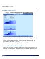
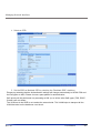
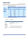
1
WBS-2400 and WBS-2400-SCT
User Manual
SW version 4.0
March 2010
Copyright Notice
©2006, 2007, 2008, 2009 Wavion, Inc. All rights reserved. Wavion is a registered trademark of
Wavion in the United States and certain other jurisdictions. Specifications are subject to change
without notice.
FCC Notice to Users and Operators
This equipment has been tested and found to comply with the limits for a Class B digital device,
pursuant to Part 15 of the FCC Rules. These limits are designed to provide reasonable
protection against harmful interference when the equipment is operated in a commercial
environment. This equipment generates, uses, and can radiate radio frequency energy and, if
not installed and used in accordance with the instruction manual, may cause harmful
interference to radio communications. Operation of this equipment in a residential area is likely
to cause harmful interference, in which case the user will be required to correct the interference
at his own expense. If this equipment does cause interference to radio or television reception,
which can be determined by turning the equipment off and on, the user is encouraged to
correct the interference by using one of the following measures:
• Reorient or relocate the receiving antenna.
• Increase separation between the equipment and receiver.
• Connect the equipment to an outlet on a circuit different from that to which the receiver is
connected.
• Consult the dealer or an experienced radio/TV technician.
This Part 15 radio device operates on a non-interference basis with other devices operating at
this frequency. Any changes or modification to said product not expressly approved by Wavion
could void the user's authority to operate this device.
WARNING: It is illegal to modify the construction of this product. Modifying the
operating frequency or enhancing the transmit output power through the use of
external amplifiers or other equipment is specifically disallowed by the
“Telecommunications Act.”
WARNING: This device is for outdoor use with conditions that no harmful interference
to authorized radio stations results from the operation of this device. This device shall not
influence aircraft security and/or interfere with legal communications as defined in the
“Telecommunications Act.” If this device is found to cause interference, the operator of this
equipment shall cease operating this device immediately until no interference is achieved.
NOTE: This device must be installed by a trained professional, value added reseller or systems
integrator who is familiar with RF planning issues and the regulatory limits in the United States of
America.
Rev 4.0
User Manual
2
READ THIS FIRST!
Important Safety Instructions
CAUTION: The exclamation point within a triangle is intended to alert the user to the
presence of important operating and maintenance (servicing) instructions in the
literature accompanying the product.
WARNING: The lightning flash with an arrowhead symbol within a triangle is intended
to alert the user to the presence of uninsulated dangerous voltage within the
product’s enclosure that may be of sufficient magnitude to constitute a risk of electric
shock to persons.
CAUTION: Read and save these instructions. Heed all warnings. Follow all
instructions.
CAUTION: Do not defeat the safety purpose of the grounding. Only use attachments/
accessories specified by the manufacturer.
CAUTION: Refer all servicing to qualified service personnel. Servicing is required
when the apparatus has been damaged in any way. For example, if the
power-supply cord or plug is damaged, liquid has been spilled on the
apparatus, objects have fallen into the apparatus, the apparatus has been
exposed to rain or moisture, it does not operate normally, or has been
dropped.
WARNING: There is a risk of personal injury or death if the WBS-2400 antennas
come near electric power lines. Carefully read and follow all instructions in this
manual. By nature of the installation, you may be exposed to hazardous
environments and high voltage. Use caution when installing the outdoor system.
WARNING: This apparatus must be connected to earth ground.
WARNING: Do not open the unit. There is a risk of electric shock inside.
CAUTION: You are cautioned that any change or modification not expressly approved
in this manual could void your authority to operate this equipment.
3 Wavion
CAUTION: There are no user-serviceable parts inside. All service must be performed
by qualified personnel.
CAUTION: The RJ45 connectors of your Wavion WBS-2400 may source DC power on
pins 4,5 and 7,8. The IEEE 802.3 standards allow for pins 4,5 and 7,8 to be used for
Power Over Ethernet. Some products may be incompatible with the Wavion Power
Over Ethernet capability. If such problems occur, make sure that the unit is
configured with the Power Over Ethernet capability set to Off (default setting). If
problems persist, use Ethernet cables that have no connections to the unused pins
4,5 and 7,8.
CAUTION: The Wavion WBS-2400 and WBS-2400-SCT can be installed in wet,
outdoor locations. Make sure closure caps are installed and all cable connections are
securely fastened and waterproofed.
CAUTION: The Wavion WBS-2400 can only be used with approved antennas.
Rev 4.0
User Manual
4
About This Manual
The following describes configuration of the WBS-2400 and WBS-2400-SCT. It is intended for
use by network engineers and administrators charged with setting up and administering Wavion
wireless networks. This manual contains the following:
• Chapter 1: Viewing the System Status: Explains the Home page with its summary of the
system status.
• Chapter 2: Managing the System Configuration: Explains how to configure the system,
upgrade the software version and install SDMA feature. Contains detailed information about
the system’s modules.
• Chapter 3: Managing Network Interfaces: Allows configuration of the Ethernet and wireless
interfaces.
• Chapter 4: SSID and VLAN Configuration: Explains how to configure BSSID and VLAN,
contains detailed information and the relationship between them.
• Chapter 5: Viewing Associated Stations: Lists the associated stations and their
configuration into VLAN.
• Chapter 6: Managing System and Station Security: Explains how to configure new users,
passwords, SNMP and HTTPS configuration.
• Chapter 7: Viewing Events: Explains how to view and configure the system event logs.
• Chapter 8: Upgrading the System Software: Provides detailed instructions for upgrading
the system software version.
• Chapter 9: Appendix: Troubleshooting: Provides tips on dealing with possible questions you
may have in working with the WBS-2400 and WBS-2400-SCT.
Related documents
The following titles are Wavion Reference documents:
•
Installation Guide
•
Firmware Upgrade procedure
5 Wavion
Contents
Viewing the System Status .......................................................................... 10
Logging in........................................................................................................................... 10
Logging out ........................................................................................................................ 10
StartUp wizard ................................................................................................................... 10
Viewing the Home Page................................................................................................... 13
To view the Home page ......................................................................................... 13
Chapter 2
Managing the System Configuration .......................................................... 15
Viewing the System Configuration ................................................................................. 15
Saving Changes........................................................................................................ 19
Managing System and Software Configurations .......................................................... 19
Performing Software Upgrades ............................................................................. 19
Managing the System Configuration..................................................................... 21
Exporting the Current Startup Configuration File ............................................... 22
Importing a New System Configuration File........................................................ 23
Restore to the Factory Default Configuration File .............................................. 23
Features Licensing- SDMA...................................................................................... 23
Installing the SDMA feature ................................................................................... 24
Viewing the System Hardware Components................................................................. 26
Debug Interface ................................................................................................................ 27
Chapter 3
Managing Network Interfaces ..................................................................... 30
Viewing the Network Interfaces Summary ................................................................... 30
Managing the Ethernet Interface.................................................................................... 32
Managing the Wireless Interface .................................................................................... 33
Setting the Operational Channel ........................................................................... 36
Setting the Transmission Power............................................................................ 37
Selecting the Interference Handling Mode .......................................................... 37
Saving Changes........................................................................................................ 39
Wireless Activity ....................................................................................................... 39
Automatic Channel Selection ................................................................................. 42
Backhaul ............................................................................................................................. 45
Bridge.................................................................................................................................. 57
Chapter 4
SSID and VLAN configuration...................................................................... 61
IEEE 802.11 and WBS-2400 Security Concepts ........................................................... 61
Security Modes: Authentication and Encryption Methods ................................. 61
Authentication Combinations ................................................................................. 62
Encryption Methods................................................................................................. 62
QoS Packets Priority ......................................................................................................... 63
Configuring WEP Security....................................................................................... 72
Configuring WPA Security....................................................................................... 74
Configuring RADIUS Server Parameters .............................................................. 74
Chapter 1
Configuring WPA2 Security.....................................................................................75
Configuring RADIUS Server Parameters...............................................................75
VLAN Configuration ...........................................................................................................76
Tagging VLAN ...........................................................................................................76
Configuring VLAN .....................................................................................................77
Configuring Multiple VLANS per SSID ...................................................................79
Management VLAN...................................................................................................81
Chapter 5
Viewing Associated Stations.........................................................................82
Viewing Stations .......................................................................................................82
Viewing Associated Stations.............................................................................................83
Viewing Specific Stations ........................................................................................84
MAC Filtering ......................................................................................................................90
Chapter 6
Managing System and Station Security ......................................................92
Viewing the Security Page................................................................................................92
Viewing the Management Configuration Page ..............................................................93
HTTP Configuration..................................................................................................96
Viewing the Authentication Pages...................................................................................96
Chapter 7
Viewing Events ...............................................................................................99
Viewing the Most Recent Events .....................................................................................99
Viewing the Full Event Log .................................................................................. 100
Navigating the Event Log..................................................................................... 101
Configuring Event Logs ........................................................................................ 102
Chapter 8
Upgrading the System Software............................................................... 105
Prerequisites.................................................................................................................... 105
Tools and data required for upgrade:................................................................ 105
Firmware Upgrade Procedure ............................................................................. 106
Roll back procedure .............................................................................................. 111
To return to the system default software version ........................................... 111
Chapter 9
Appendix: Troubleshooting........................................................................ 113
Basic Troubleshooting .......................................................................................... 113
LED Description ..................................................................................................... 114
7 Wavion
Introduction
Wavion is glad to have the opportunity to offer the WBS2400 family of products as the best wireless
coverage solution for your project requirements. Wavion’s next-generation base stations, referred to as
spatially adaptive WiFi Base Stations, are designed specifically to address shortcomings in current outdoor
access points for rural and metro WiFi applications. Wavion’s powerful digital beam-forming and space
division multiple access (SDMA) technologies - the next-generation of multiple-antenna technology - address
limitations in coverage, penetration, and capacity of existing WiFi technology, and provide significant
performance and cost advantages compared to current conventional WiFi solutions.
The WBS2400 and WBS-2400-SCT Base Stations
WBS2400 Key Benefits:
• Exceptional coverage, range, throughput,
network capacity, scalability, and reliability
• Excellent building and wall penetration
• Uniform coverage and enhanced non-lineof-sight operation
• High interference resilience
• Enhanced mobility support
• Simple deployment and low infrastructure
and operating costs
• Full compatibility with standard 802.11b/g
clients
Rev 4.0
User Manual
8
Figure 1.1: Shows the relationship between the WBS-2400 hardware modules.
Figure 1.1
HW Block diagram
RF
Wavion
ASIC
RF
RF
CPU
Wavion
ASIC
RF
RF
RF
•
CPU – Control and synchronize the whole system performance
•
Wavion ASIC - Smart RF technology resides in the ASIC and software
•
WBS-2400- Six RF modules and Antennas - Standard off-the-shelf components and antennas
•
WBS-2400-SCT -Three RF modules and Antennas- Standard off-the-shelf components
•
Wired Data – 10/100 Base-T Ethernet terminals with POE in or optional output.
9 Wavion
Viewing the System Status
Chapter 1
Viewing the System Status
The Home page shows a summary of status data of the system. From within this page, you can
quickly link from fields to other related pages for more information.
Logging in
The default IP address of the unit is IP: 192.168.1.1 and mask: 255.255.255.0.
To log-in, type “admin” in the username field, and “admin” in the password field.
Logging out
Is possible to log-out at any time by pressing the “Logout” button on the upper right-hand side
of the screen.
StartUp wizard
Upon login, the start-up wizard appears. This wizard is composed of 3 pages:
◊
Quick Installation guide
◊
IP Address Configuration
◊
Automatic Channel Selection
Moving to one page to the other is done by pressing the “Next” button. From the “IP setting”
page is possible to skip the Wizard. The wizard stops after the ACS. The page shown is the ACS
results, where is possible to check the status of the spectrum around the WBS area.
The wizard will be activated every login. To deactivate the wizard go to the “System “ menu
page and disable the Wizard through the “Startup Wizard” drop-down list at the bottom of the
page.
Viewing the System Status
Figure 1.2
Quick Installation Guide
Figure 1.3
IP Address Configuration
You can skip the Wizard in this page by pressing the “Skip Wizard” button.
11 Wavion
Viewing the System Status
Figure 1.4
Automatic Channel Selection
After pressing “Start” a channel scanning will be performed.
The last page of the wizard is the ACS results. From this page starts the normal functionality of
the GUI.
Figure 1.5
Rev 4.0
Automatic Channel Selection
User Manual
12
Viewing the System Status
Viewing the Home Page
To view the Home page
• Click Home.
The Summary Status page is displayed.
Figure 1.6
Home: Summary Status Page
The following fields appear on the Summary Status page:
Table 1.1
Home: Summary Status Page
Field
Description
BST Status
Associated Stations
Links to Associated Stations page
Active SSID
Service Set Identifier; links to Editing SSID page
13 Wavion
Viewing the System Status
Table 1.1
Home: Summary Status Page
Field
Description
System Identity
Links to System Configuration page
System Description
Description of the device as written in MIB-II SysDescr
OID
System Up Time
Total time since system was switched on or last reinitialized
System Contact
Administratively-assigned email address of system
operator
System Name
Administratively-assigned name for this managed node;
the node's fully-qualified domain name.
System Location
Administratively-assigned physical location of this node
(e.g. ‘telephone closet, 3rd floor')
System Coordinate
Display the unit’s Latitude and Longitude
Regulatory Domain
Display the unit regulatory domain according to
802.11d
IP Configuration
Links to System Configuration page
IP Address
The current IP address of the unit
Subnet Mask
The current subnet mask used to establish the
broadcast domain.
Default Gateway
The current IP address of the default gateway.
Network Interfaces
Links to Network Interfaces Summary page
Network Interfaces
Links to interfaces configuration page
• Ethernet
• Wireless
Operational Status
Up/down
Transmission Rate
Maximum transmission rate on the interface in Mbps
Self Backhaul
Rev 4.0
BST role
Display current BST self backhaul configuration and link
to the configuration page
Peer BST
Display number of connected peers and link to the
connected BST page
User Manual
14
Managing the System Configuration
Chapter 2
Managing the System Configuration
The System Configuration page displays system identification parameters like, IP information,
system location servers etc. The other system pages allow updating of the software version and
system configuration, and a view of the system components.
Viewing the System Configuration
To view the System Configuration page
• Click the System menu item.
The System Configuration page displays.
Figure 2.1
System Configuration Page
Managing the System Configuration
The following fields appear on the System Configuration page:
Table- 2.1 System Configuration
Field
Description
System Identity
System Description
Description of the device as written in MIB-II SysDescr OID
System Up Time
Total time since system was switched on or last re-initialized
System Contact, Name,
Location, Time Zone,
Coordinates
These parameters are for the user convenience while
observing system status via WEB or NMS
IP Address
Configuration
Configured Boot Protocol
Get Static IP or from DHCP server
Configure IP Address,
Subnet Mask and Default
Gateway
Configure the unit IP parameters
Management VLAN
configuration
Select Management VLAN List of configured VLAN. Select one as the Management VLAN
VLAN External ID
VLAN ID number configured from the VLAN Switch for
Management VLAN traffic.
Ethernet tagging
Enable to VLAN tag all Management traffic
SNTP
Simple Network Time protocol
Time Synchronization
Disable the Time Synchronization or set the Static IP address
of the SNTP server or DHCP
IP address of SNTP
Servers
Enter the IP address of your desired SNTP servers to sync all
system messages to calendar time
Configure TFTP Server
IP Address of TFTP Server The IP address of the default TFTP server; can be overridden
in the Software Upgrade page for a temporary SW download
System Management
Configuration
Rev 4.0
Management from
Wireless
Enable/Disable
Startup Wizard
Enable/Disable the Startup Wizard
User Manual
16
Managing the System Configuration
This page contains basic static information on the system, such as contact details, and IP
addresses. Several changes are recommended on this page.
Setting System Contact Details
In the System Identity area, in the System Contact field, enter the contact email address of the
net owner.
Setting the IP Address Configuration
Change the IP address to allow the full configuration. The Current IP Address Configuration
area lists a default IP address; it is possible to perform initial testing with this address, but it is
highly recommended to change the IP address.
To change the IP address
In the IP Address Configuration section,
1. For a DHCP obtained address, select DHCP. Following a reboot, the WBS-2400 will
automatically obtain and IP address, Subnet mask, and Default Gateway from the DHCP
server.
2 To allow entry of a new IP address, select Static from the Configured Boot Protocol
dropdown list.
3 In the Configured IP Address field, enter the required IP address.
4 In the Configured Subnet Mask, enter a valid network mask.
Note: The system must be rebooted for these changes to take effect.
Setting the Management VLAN configuration
The purpose of the management VLAN is to segment the Management and the Clients data
traffic. It also provides an option for customers to keep an Open SSID for public traffic and
simultaneously manage the WBS-2400 traffic over a separate VLAN (that may be linked to a
secured SSID). The management VLAN can be selected out of the enabled VLAN list.
Note: Only one VLAN can be defined as the Management VLAN in the
WBS-2400 system.
The configuration of the Management VLAN takes effect immediately.
This means that setting the Management VLAN has to be done in 2 steps:
17 Wavion
Managing the System Configuration
1. Applying the VLAN parameters (external VLAN ID and tagging mode) using the
existing management traffic, and selecting the desired VLAN to be the Management
VLAN on the Administration page. After this stage the current wire-line connection
to the system GUI will drop.
2. Saving the parameters – using the new Management VLAN, i.e. over the tagged
VLAN.
To enable VLAN management
1. Apply the VLAN parameters (external VLAN ID and tagging mode) using the existing
management traffic or create a new VLAN ID.
2. Select the desired VLAN ID for the Management VLAN traffic.
3. Click Apply and Save
Note: The configuration of the Management VLAN takes effect
immediately. Therefore setting the Management VLAN is done over the
"old" VLAN (default is VLAN-1 untagged), while saving is done over the
"new" VLAN.
The 3rd step in "To enable VLAN management has to be done over a
different machine/ the new VLAN.
Setting the System Management Configuration
You can decide to allow system management from the Wireless Interface, or to allow
management only from the Ethernet Interface, for security purposes.
To enable or disable system management from the Wireless
Interface
In the System Management Configuration area, in the Management from Wireless field, from
the dropdown list, select enabled to allow system management from the wireless interface, or
Disabled to restrict system management to the Ethernet Interface.
To enable or disable Startup Wizard
From the dropdown list, select “Disabled” to stop performing the Startup Wizard after each
login.
Rev 4.0
User Manual
18
Managing the System Configuration
Saving Changes
Note: After making changes on this page, you must click both Apply and Save,
or the changes do not remain in effect after the next reboot.
1. Click Apply.
2. Click Save.
Managing System and Software Configurations
You can change the system startup configuration, upgrade the software version from the
system software tabs and install the SDMA feature license.
To access the system software tabs
• Click System Software from the menu, as a sub-item of the System menu item.
The system software tabs display, consisting of the Software Upgrade tab for managing the
system software version, the System Configuration tab for managing the system configuration,
and the Features Licensing tab to install/uninstall the SDMA feature.
Performing Software Upgrades
The Software Upgrade tab shows details about the current software version and allows setting
properties required to install a new software version. It is also possible to return to the factory
default software, backup the current version of the software and return to a previously backed
up version of the software.
Figure 2.2
Software Upgrade Tab
Returning to the Default Software Version
You can reinstall the default software version, using one of two options:
19 Wavion
Managing the System Configuration
1. Default Except IP – In this case, the unit will lose its current setting without changing the IP
address. This option is convenient when choosing to return to default from a remote
location.
2. Default – In this case, the unit will lose its current setting and gets system defaults of IP:
192.168.1.1 and mask: 255.255.255.0
To return to the system default software version
1. Click Default or Default Except IP.
2. Click OK
A warning popup displays.
Figure 2.3
Default Popup
The system returns to the default software version and default IP and mask settings.
Note: Is possible to return to factory defaults using the reset pushbutton.
Press the button firmly until the “STATUS” LED blinks fast with red light
(around 40 seconds).
The reset button differs in location according to the WBS HW model:
◊
If your WBS has a connection box, the reset pushbutton is
located in the box.
◊
If your WBS has only ETH and TEST ports, the reset button
is located in the PoE injector next to the PoE output port.
The configuration, SW version, and SDMA license status will revert to
default.
Rev 4.0
User Manual
20
Managing the System Configuration
Upgrading the Software Version
A full description of upgrading the software version is given in upgrading the System Software
section in Chapter 7.
Backing Up the Current Software Version
You can backup the software version currently installed on the system. This can be used before
upgrading to a new version with which you do not have experience.
To back up the current version of the software
• Click Backup.
The current version of the software is saved, and can be restored to the system if necessary.
Restoring the Last Saved Software Version
If you backed up a software version before upgrading to a new one, it is possible to return to
the previous version.
To return to a previous system software version
• Click Restore.
The last backed up version of the system software is restored to the system.
Managing the System Configuration
On the System Configuration tab you can manage current system configuration file name and
the configuration management parameters. You can also restore the factory default
configuration file, export the current system configuration file, or import a new system
configuration file.
Figure 2.4
System Configuration Tab
The following fields appear on the System Configuration tab:
21 Wavion
Managing the System Configuration
Table- 2.2 System Configuration tab
Field
Description
Current
Configuration File
Current Startup
Configuration File
File currently used to configure system on startup. This field is
also used to export the current configuration file. Rightclicking on the file name allows you to save the current
Startup Configuration File on you local disk. See Exporting the
Current startup Configuration File.
Import New
Configuration File
To import a saved configuration file
Import Protocol
TFTP/HTTP
Configuration file can be imported using either TFTP or HTTP
protocols
TFTP Server - IP
Address...
IP address of the TFTP server, if, for the current downloading,
it is not the same as the default TFTP Server. Setting the
value here is only relevant for this download and does not
hold across a Reboot.
The Default TFTP Server is set in the System Configuration
page. See Viewing the system Configuration
New Startup
Configuration File
Path including the .swcc file being HTTP downloaded; select
path using the Browse button which is activated if HTTP is
selected as the import protocol
Factory Defaults
Used to restore the factory default startup configuration.
Clicking here erases the configuration file that contains all the
changes you made to the unit except the unit's IP address.
See Restore the Factory defaults
Import System
Configuration
Used to import a new startup configuration from a previously
saved file.
See Importing a New System Configuration file
You have the option of exporting the current startup configuration, importing a new startup
configuration or of restoring the factory default configuration file.
Exporting the Current Startup Configuration File
To export the current system configuration
1. Click on the name of the current software configuration.
A File Download dialog box will appear listing the Name, Type, and From IP address.
A File Download dialog box will appear listing the Name, Type, and From IP address.
Rev 4.0
User Manual
22
Managing the System Configuration
A Save As dialog box will appear.
5 Choose the save in folder, create the correct File name, and click on the Save button.
Importing a New System Configuration File
To import a new system configuration
Select the import protocol to be used, either TFTP or HTTP.
If TFTP is selected, enter the IP address of the TFTP server to be used for the download, if it is
not the default server.
In the New Startup Configuration File, click Browse and select the file location.
Click Import Startup Configuration.
Note: Do not click Save.
Reboot the system to apply the new configuration.
The new configuration files take effect.
Restore to the Factory Default Configuration File
To restore the factory default configuration file
Click Factory Defaults.
Note: This procedure erases the configuration file that contains all the
changes you made to the unit except the IP address.
Note: Do not click Save.
Reboot the system to apply the factory default configuration.
Features Licensing- SDMA
On the Features Licensing tab you can manage the installation of the SDMA feature. This
feature is managed through a one time license installation. This license is issued on a unit by
unit basis. That means that a license issued will work only with the unit the license was issued
for.
In order to get a license, please send the Tech Support Report and your company details to:
[email protected]
23 Wavion
Managing the System Configuration
For help creating the Tech Support Report, please refer to Debug Interface section. Please send
one Tech Support Report per each WBS-2400 where you want to enable the SDMA feature.
Figure 2.5
Features Licensing Tab
Installing the SDMA feature
Upon reception of the license key, type it in the “Key” field of the “License Featuring” tab.
Click on the “Install” button. A pop-up window will appears.
Figure 2.6
Features Licensing Tab- SDMA Installation
After acceptance, the feature will be installed but not active
Figure 2.7
SDMA after Installation
For SDMA activation, the system configuration must be saved and the unit must be rebooted.
Rev 4.0
User Manual
24
Managing the System Configuration
Figure 2.8
SDMA Installed and Active
Note: Although the feature is installed, you can enable and disable it
through the Wireless tab in Network-> Wireless menu.
25 Wavion
Managing the System Configuration
Viewing the System Hardware Components
The System Hardware page lists the components of the system.
Figure 2.9
System Hardware Page-WBS-2400
Figure 2.10
System Hardware Page-WBS-2400-SCT
The following information is displayed on the System Hardware page for each component.
Rev 4.0
User Manual
26
Managing the System Configuration
Table- 2.3 System Hardware page
Field
Description
Product
Number
An internal ID which identifies the components of the system.
There are no field replaceable units. This information may be
used to identify the hardware components.
Serial
Number
An internal ID which identifies the date of manufacture,
production lot, and individual component. There are no field
replaceable units. This information along with the product
number may be used to identify the specific hardware
component.
Antenna Type
The Antenna Type indicates the default antenna type that is
installed in the unit.
Although WBS-2400 antennas can be detached from the unit,
they should be considered as integral part of the WBS-2400. The
beamforming capability takes into account the specific attributes
of the antennas. Replacement of antenna should never be done
without official instructions from Wavion Technical Support
person
Debug Interface
The Debug interface page allows Wavion's technical support team to get critical information
about the status of your system Software and Hardware.
In case of faulty system behavior you may be asked by a Wavion technical support member to
save the file listed in the Debug Interface page, or to enter a code that will generate special file
for engineer's inspection.
27 Wavion
Managing the System Configuration
Figure 2.11
Debug Interface Page
Table- 2.4 Debug Interface page
Field
Description
Common Debug
Interface File Upload
In rare cases you will be asked by Wavion technical person to upload
a file into the system to help critical issue debugging.
Module Control
ID/Args
These codes will be given by Wavion Technical support person to
load to the system in order to get help with critical debugging.
Tech. support
button
This button creates a Tech Support Report file with all the unit’s
configuration and other information needed by Wavion Tech Support
Department in order to debug a problem.
File List
This list contains debugging files that helps Wavion technical support
to define HW or SW problems in field.
Please send this file to Wavion technical support for analyzing your
system conditions.
ARP PING
This tool test the connectivity of the WBS by sending a L2 PING
towards a device in a specific broadcast domain
Source IP address
IP address to be set as SENDER in the ARP message. This IP should
be an available address and must lay on the same subnet as the
destination IP address
Destination IP address
IP address to be set as TARGET in the ARP message. This IP address
must lay on the same subnet as the source IP address
Rev 4.0
User Manual
28
Managing the System Configuration
VLAN
Select the VLAN (broadcast domain) where the IP addresses should
be valid
Optional Parameters
Leave it blank for a repetition of 5 PING. Select “–t” for a non-stop
PING stream.
29 Wavion
Managing Network Interfaces
Chapter 3
Managing Network Interfaces
You can view the status of the network interfaces. There is a summary page and a separate
page where each interface can be managed.
Viewing the Network Interfaces Summary
To view the Network Interfaces Summary page
• Click Network Interfaces in the menu.
Depending on whether the base station has an embedded Ethernet Switch or not the view of
the Network Interface Summary page will be different
Figure 3.1 Network Interfaces Summary for a system without embedded switch
You can click Ethernet or Wireless on either the page or the menu bar to view the Ethernet or
Wireless Interface pages.
Managing Network Interfaces
Figure 3.2 Network Interfaces Summary for units with embedded Ethernet Switch
You can click ETH A, ETH B, ETH C or Wireless in the page to view the Ethernet or Wireless
Interface pages. Alternatively, you can click Ethernet or Wireless in the menu bar to view
corresponding interface pages
The following fields appear on the Network Interfaces Summary page:
Table- 3.1 Network Interfaces Summary page
Field
Description
Interface Name
List of network interfaces
Speed
Maximum transmission rate on the interface in Mbps
Status
Indicates whether interface is up or down
Transmission
(bytes)
Current total transmission in bytes through the interface
Reception (bytes)
Current total reception in bytes through the interface
Bridge
Configuration
Shows whether the data or multicast peer-to-peer traffic is
allowed or blocked
Multicast Traffic
Policing
Shows the maximal traffic allowed for Multicast/Broadcast
data in each interface in Kbps and the dropped packets as
en effect of that.
Options
31 Wavion
Apply
Click to have your changes take effect temporarily
Save
Click to have your changes remain in effect after a reboot
Cancel
Click to clear your changes; this is only possible if Apply or
Save were not clicked
Managing Network Interfaces
Managing the Ethernet Interface
The Ethernet page displays status and configuration parameters, and statistics information for
the Ethernet interface.
To view the Ethernet interface parameters and statistics.
• Click Ethernet either from the Network Interfaces Summary or as a sub-item of the Network
Interfaces menu item.
Figure 3.3 Ethernet Page for systems without embedded switch
Table- 3.2 Ethernet page ( no embedded switch)
Field
Description
Status and
Configuration
Interface
Up/Down
Link Speed
10/100
Duplex
Indicates whether transmission through the interface is
full duplex or half duplex
Default VLAN
Default VLAN of this interface, when working in VLAN
mode
Options
Rev 4.0
Negotiation
Auto/Manual
Link Speed
10/100
Duplex
Full/Half
User Manual
32
Managing Network Interfaces
Figure 3.4 Ethernet Page for systems with embedded switch
Table- 3.3 Ethernet page ( embedded switch)
Field
Description
Configuration
for each Ethernet port: ETH A, ETH B, ETH C
Port
Enable/Disable of the port
Negotiation
Auto/Manual
Speed
Link Speed [Mbps]-Options: 10/100
Duplex
Indicates whether transmission through the interface is
full duplex or half duplex-Options: Full/Half
POE
This parameter will appear only if the unit is powered
from AC
Option for POE output from Ethernet port B (ETH B).
Options: OFF/ON (POE output)
Input Power Source
POE Connector – the units is powered from POE injector
AC Power Connector – the unit is AC powered
Statistics
Link
Status of the link (Up or Down)
Rx (packets)
Total number of received packets from Ethernet
Tx (packets)
Total number of transmitted packets towards Ethernet
Managing the Wireless Interface
The Wireless menu displays three pages and one sub-menu:
33 Wavion
Managing Network Interfaces
•
•
Wireless pages:
o
Wireless (configurable): Status and Configuration details, Interference Handling
Mode, Frequency Planning Consideration, Traffic Optimization.
o
Wireless Activity: Statistics, RF Channel Parameters, SDMA parameters.
o
ACS (Automatic Channel Selection)
SSID-VLAN submenu: For details on this sub-menu please refer to Managing SSID
To view the Wireless interface parameters and statistics.
• Click Wireless either from Home Summary Status or Wireless as a sub-item of the Network
Interfaces menu item.
The Wireless page displays.
Figure 3.5 Wireless Page
The following fields appear on the Wireless page:
Table- 3.4 Wireless page
Field
Description
Status and
Configuration
Rev 4.0
User Manual
34
Managing Network Interfaces
Table- 3.4 Wireless page
Field
Description
Operational Status
Up/Down
BSSID
Identifier MAC address of the BST
Operational Channel
The wireless channel used by the unit. See Setting the
Operational Channel
Transmission Power
Default Max=1 for maximum Tx Power and Min=6 for lowest Tx
Power. It's a 3dB steps. Should be set to maximum for most
applications.
Beacon Period (Kusec)
Amount of time between beacons in kilomicroseconds. One Kusec
equals 1,024 microseconds, which is close to 1 millisecond.
Default is 100ms. Not configurable.
DTIM Period (Beacon
intervals)
Determines how often the beacon contains a Delivery Traffic
Indication Message (DTIM). This message “wakes up” any CPE in
power-save mode. Not configurable
Range
Sets the maximal distance for an associated CPE based on radio
propagation delay. Values: 2.8,5,10 and 15Km
Association aging
timeout
The amount of time after which an inactive CPE (a CPE that
neither received nor transmitted data) is disassociated from the
BST. The minimum value is 5 minutes, maximum is 30 minutes.
The default value is 15 minutes.
Selects the way the system handles the interferences. It can be
set to any of the following four modes:
Interference
Handling Mode
•
Interferences Mode
•
Moderate Interferences Mode
•
High Interferences Mode
The recommended mode is Interferences mode
Frequency Planning
Consideration
•
Standard: System works in standard (20MHz) channel
separation
•
Overlapping: System is optimized for 15MHz channel
separation
Note: Enabling the Overlapping mode will decrease the Tx power
by about 3dB.
Traffic Optimization
35 Wavion
Managing Network Interfaces
Table- 3.4 Wireless page
Field
Description
•
•
•
Capacity optimization (802.11g only): CPE wishing
to associate to the BST must support 802.11g protocol.
Legacy mode (802.11b/g): This mode allows 802.11b
CPE to associate.
QoS Optimization: System is optimized for VoIP
deployments. CPE wishing to associate to the BST must
support 802.11g protocol. The CPE should support
working with multicast/broadcast data at 12Mbps.
Configure Packet priorization for QoS (per BSSID/SSID)
is a shortcut to the SSID-VLAN/BSSID list where the QoS
configuration is performed on BSSID/SSID basis.
SDMA mode
Enables or disables the use of SDMA. The feature must be
installed before usage. Please refer to Installing the SDMA
Feature
Options
Apply
Click to have your changes take effect temporarily
Save (from the menu
bar)
Click to have your changes remain in effect after a reboot
Cancel
Click to clear your changes; this is only possible if Apply or Save
were not clicked
On this page you can configure the wireless interface. There are several recommendations for
this page.
Setting the Operational Channel
The wireless activity in a channel is an important factor in network performance. Channel
activity is indicated by the Idle Time; low values indicate high activity in the channel.
High numbers in “Other WiFi activity” means interference from a co-located channel system.
“Interferences” activity represents adjacent channel systems.
Note: Measurements made to select a channel are best performed when
there is limited or no traffic to WBS-2400.
Rev 4.0
User Manual
36
Managing Network Interfaces
To set the Operational Channel
In the Status and Configuration area, from the dropdown list in the Operational Channel field,
select the channel on which the system runs. Default is Channel 6: 2437 MHz.
Setting the Transmission Power
Be sure the Transmission Power is set to the maximum; the radio button in this field should be
set on the setting closest to the word Max.
Selecting the Interference Handling Mode
The default Interference Handing Mode is Interferences Mode. This mode adaptively
changes the system sensitivity according to the interference conditions in the environment. In
some cases, using the other modes may result in better performance than Interferences
Mode due to limitations with tracking the exact interference. For the identification of the
different cases the “Channel Parameters” section in the “Wireless Activity” Page must be
consulted.
As a rule of thumb, when the sum of “Other WiFi activity” and “Interferences” activity
percentages is more than half the percentage of “Idle Time”, changing the interference
handling mode to the next mode may help to improve the overall performance of the system.
◊
From “Interferences Mode” change to “Moderate Interferences Mode”.
◊
From “Moderate Interferences Mode change” to “High Interferences Mode”.
After changes please allow 10 minutes for the interference mitigation algorithm to reach steady
state. Check the performance of the system before you change to the next mode.
Frequency Planning Consideration
When high-density deployments are needed, one of the main issues is the frequency planning
and re-use. IEEE 802.11 define 20MHz channels that overlap. In 802.11b/g there are only 3
channels that do not overlap. These channels are channel 1 (2412MHz), channel 6 (2437MHz)
and channel 11 (2462MHz).
The Wavion base station is capable of working in 15MHz channel separation, while having
minimum overlapping effect on neighboring (15MHz) channels. At 2.4GHz band (802.11b/g), that
means that there can be 4 non-overlapped channels: Channel 1 (2412MHz), channel 4
(2427MHz), channel 8 (2447MHz), and channel 11 (2.462MHz). Despite this, any standard
802.11 CPE will be able to work with the WBS without throughput degradation.
The WBS-2400 also reduces the Tx power automatically when in Overlapping mode to allow
better signal quality in sites where several base-stations are co-located. However, a slightly larger
BST separation of 2 meters between units must be kept.
37 Wavion
Managing Network Interfaces
Selecting the Traffic Optimization
The WBS-2400 and WBS-2400-SCT is set by default to “Capacity optimization”. This mode
supports only CPE that can work in 802.11g protocol. This mode is optimized to achieve a higher
capacity when compared to 802.11b systems.
When older, 802.11b CPE are present in the covered area, is possible to allow their association to
the base station. In order to do that, please set the base station to work in “Legacy mode”.
Legacy mode allows the connection of 802.11b and 802.11g CPE.
Wavion base station supports QoS applications, specifically, VoIP and Video. When “QOS
optimization” mode is enabled, the system allows only 802.11g CPE to connect. QoS Optimization
adds another level of data handling. Data is prioritized by its QoS settings, several other
parameters in the system are set automatically to give VoIP the best conditions to work.
In order to better support real-time applications, the minimum rate used by the system is
12Mbps. Please check the CPE you are using supports multicast/broadcast data sent at this rate.
This mode has best results using an outdoor CPE, like Ubiquiti’s NS2, when connected in good
SNR (greater than 15dB).
QoS support is done by prioritization. The packets prioritization over WiFi is based on 4 Access
Categories defined by the WMM standard:
◊
Voice traffic
◊
Video traffic
◊
Best effort traffic
◊
Background traffic
A packet arriving at the Ethernet interface of the base station will be classified to one of the
Access categories. The classification can be done using ToS, DSCP or VLAN Priority. For
classification configuration please refer to paragraph QoS Packets Priority.
Note: For two way QoS priorization ( for example in VoIP application), a
WMM supporting CPE must be used for uplink QoS classification. Failing to
do so will cause a bad functionality of priorization in the system.
A maximum of 20 concurrent calls with high quality (MOS > 3.8) and high TCP traffic, or 15
video concurrent streams (of 1Mbps each) are achieved when "QoS Optimization" is selected on
the WBS management interface and an NS2 is used as CPE.
Rev 4.0
User Manual
38
Managing Network Interfaces
SDMA mode
Wavion’s SDMA technology sends two concurrent data streams from the base station to two
different users. This doubles the downlink capacity of each base station. The feature must be
installed prior to enabling it. Please refer to Installing the SDMA Feature.
SDMA will work with CPE that are connected to the WBS with an SNR higher than 15dB, and
when the CPE Downlink modulation is above 5.5Mbps in 802.11b mode or 54Mbps when working
in 802.11g protocol.
When two WBS are connected through Self-backhaul, the SDMA feature will work only towards
the access part and not on the Self-Backhaul link itself.
The feature has limitations which justifies the ability to enable and disable the feature according
to the application:
◊
◊
Long Range links: When the Range parameter in the Status and Configuration
section (in the Wireless tab) is set to a value of 10Km or 15Km, the SDMA feature
is disabled automatically.
VoIP: SDMA doubles the traffic in the downlink direction. When VoIP is the main
application implemented in the system, symmetrical, two-way traffic is needed.
Because of the different mechanisms this feature uses, it is recommended to
disable the feature.
Saving Changes
Click Apply.
Click Save.
Wireless Activity
Figure 3.6 Wireless Activity Page
39 Wavion
Managing Network Interfaces
The following fields appear on the Wireless Activity page:
Table- 3.5 Wireless Activity page
Field
Description
Channel Parameters
Noise Level
The level of the system noise power in dBm. Nominal noise level
without interference is -97 dBm. Higher values indicate higher
noise levels due to interference presence.
Note: Noise level will show N/A after reboot. It will update after
4~6 minutes up time when the Calibration cycle 0 is done.
Beacon Success Ratio
The ratio, in percentage, between the number of beacons that
the BST transmitted and the beacons that the BST should have
transmitted. A low percentage indicates lost beacons probably
due to high activity in the channel (CCA is high) that does not
enable transmission.
Idle Time
The relative amount of time (in percentage from the 100% of the
total time) that the system is neither transmitting nor receiving.
Maximum performance from the unit is achieved when this
number is low. Together with the “Interferences” and “Others”
counters helps to detect high-interfered links. It is affected from
the environment activity of other wireless devices and from its
own activity.
Tx Activity
The relative amount of time (in percentage from the 100% of
the total time) in which Channel was busy transmitting data.
Rx Activity
The relative amount of time (in Percentage from the 100% of the
total time) in which Channel was busy receiving valid data that
was successfully decoded and was aimed to the WBS.
Other WiFi activity
The relative amount of time (in Percentage from the 100% of the
total time) in which Channel was busy receiving valid data not
aimed at the specific WBS (data from other networks).
Interferences
The sum of Invalid CS Packets (reception that failed to be
modulated correctly) and Invalid ED Packets (energy was
detected but no valid carrier was found) activities (in Percentage
from the 100% of the total time).
SDMA Parameters
SDMA activity
Rev 4.0
The percentage of packets that were transmitted using SDMA
from the total amount of packets transmitted.
User Manual
40
Managing Network Interfaces
Table- 3.5 Wireless Activity page
Field
Description
Total Tx capacity
The calculated average throughput that was achieved (in Kbps)
since the last screen refresh.
The estimated available throughput based on parameters of last
transmissions, SDMA activity and channel parameters. When the
Estimated WBS capacity throughput in last transmission and SDMA activity is near zero ,
the field shows the maximum available throughput :
available
◊ When SDMA is disabled: 29593 kbps.
◊ When SDMA is enabled: 51200 kbps
Statistics
Total amount in Transmission and Reception of the following
parameters
Bits
The number of bits transmitted/received.
Bytes
The number of bytes transmitted/received.
Unicast Packets
The number of Unicast Packets transmitted/received.
Non-Unicast Packets
The number of Non-Unicast Packets transmitted/received.
Errors
The number of errors that occurred during
transmission/reception.
Discarded
The number of discards that occurred during
transmission/reception.
Reset Counters Button
Resets the counters. In order to see new numbers refresh the
page.
Options
41 Wavion
Apply
Click to have your changes take effect temporarily
Save (from the menu
bar)
Click to have your changes remain in effect after a reboot
Cancel
Click to clear your changes; this is only possible if Apply or Save
were not clicked
Managing Network Interfaces
Automatic Channel Selection
Figure 3.7 Automatic Channel Selection Page in Standalone Mode
The Automatic Channel Selection (ACS) is a tool for automatic scanning the frequency channels,
and selecting the best channel based on the activity and the interference level of each channel.
It is useful for both standalone deployment and in assisting tool for multi-BST deployment.
The ACS scans the selected channels list, displays the scanned results to the user, and
recommends the best channel for operation.
The scanning activation and results retrieval are available by SNMP to enable centralized
operation of the channel scanning and selection.
How to initiate Scan in Standalone Mode:
Pressing scan button in the ACS page will initiate the scan process. During the process, the
system will reboot to Scan Mode, perform the scan and afterwards will automatically reboot
back to Operational Mode.
Rev 4.0
User Manual
42
Managing Network Interfaces
Note: During scan mode the system will not be operational, i.e. clients
will not be able to associate, although beacons will continue to be
transmitted.
How to return to Operational Mode:
The system will automatically return to operational mode with the recommended channel
selected by the ACS algorithm unless the “Automatic set to recommended channel and reboot”
checkbox is not checked. In this case the system will return to the previous selected channel
after the scanning.
During any time in which the system is not in operational mode, selecting a channel from
"Operational channel" list-box and pressing reboot will return the system to operational mode
with the selected channel. The list-box appears during the scan.
The following fields appear in the Automatic Channel Selection page:
Table- 3.6
Field
Automatic set to
recommended channel
and reboot
Scan results
43 Wavion
Automatic Channel Selection page
Description
• Enabled - After completion of the frequency
scan, the unit will choose the best fit
frequency and automatically reboot the
system.
• Disabled - The user has to choose a channel
from Channel Selection and reboot to return
unit in Operation.
Managing Network Interfaces
Table- 3.6
Automatic Channel Selection page
Field
Description
Scan Status
Status of the system mode.
• Not in ACS mode - is shown during
operational mode
• Scanning - is shown during scan
Recommended channel The best channel that was chosen based on scan results. It
selects the best channel from channels selected in the
"available channel" list. The recommended channel is selected
based both on noise level and channel activity.
Rev 4.0
Total CCA activity
Total activity in the selected channel in percentage
Noise level
Level of the noise as measured by the BST
TX failure rate
Percentage of the times that the system failed to transmit due
to the channel’s activity
User Manual
44
Managing Network Interfaces
Backhaul
The WBS-2400 and WBS-2400-SCT have two important features to help the operator to deploy
the systems more efficiently.
Those features are:
◊
Backhaul CPE
◊
Self-Backhaul (SBH)
Figure 3.8 Connected Backhauls page
Table- 3.7
Connected Backhauls
Field
Description
Backhaul BST Link
Information
Link #
Index of the Self-backhaul link
MAC Address
MAC Address of the peer BST.
Link Status
Status of the SBH link:
◊ Up: Link is working
◊ Unidirectional.: Link is not working, configuration
problems
◊ Down: Link is not working
Link Quality
Quality of the SBH link:
◊ Excellent
◊ Good
◊ Fair
◊ Poor
45 Wavion
Managing Network Interfaces
Field
Description
Operational Rate
The rate of the data transmitted to Peer BST on the SBH link.
Rx Rate
The rate of the data received from Peer BST on the SBH link.
Tx Bytes
Amount of bytes transmitted
Rx Bytes
Amount of bytes received
RSSI
The symmetrical Rx Signal Level of the link
Details
Details of the Connected BST
Backhaul CPE Link
information
Station's MAC Address
MAC (Media Access Control) address of the associated station
Power Save State
Value of Doze in this field indicates that the associated station is in
power save mode
WMM support
Value of 'yes' in this field indicates that the associated station
supports the WMM protocol. . For more information about working
with QoS please refer to “QoS Packet Priority”
WDS
For this feature the CPE should support WDS. “Yes” will indicate
WDS support
The supported CPE are Ubiquity NS2/PS2 running version 3.2.2, and
Ruckus running version 4.4.2.0.28.
Rev 4.0
Tx Rate [Mbps]
PHY Rate (modulation) at which the base station currently transmits
to the associated station
Rx Rate [Mbps]
PHY Rate (modulation) at which the associated station currently
transmits to the base station
SSID
SSID to which the associated station is associated (should be the
'backhaul SSID')
VLAN
VLAN name to which the station is bound. (should be the VLAN of
the 'backhaul SSID')
UL Quality
Quality of the Up Link: Reported by WBS.
◊ Good
◊ Poor
DL Quality
Quality of the Down Link: Reported by CPE
◊ Good
◊ Poor
Tx[Bytes]
Number of bytes transmitted by BST to the station
Rx[Bytes]
Number of bytes received by the BST from the station
RSSI[dBm]
The Received Signal Strength Indicator power received by the BST
from the associated station.
User Manual
46
Managing Network Interfaces
Field
Description
State
State of which the station is connected
Backhaul CPE
The Backhaul CPE feature allows to create an SSID that together with the CPE associated to it
creates a trunking interface. This interface is capable of tunneling tagged VLAN between the
two ends (CPE and BST).
Only one SSID can be configured as backhaul SSID. The number of VLAN capable to be trunked
is the number of available VLAN in the system (15 in SSID-VLAN mode, 5 in BSSID mode).
It is highly recommended to connect no more than 20 CPE to the backhaul SSID to avoid
bandwidth stagnation.
This feature works only with specific CPE models, as it uses the WDS feature.
The supported CPE are Ubiquity NS2/PS2 running version 3.2.2 and up, and Ruckus running
version 4.4.2.0.28.
Figure 3.9 Backhaul CPE Configuration
How to create a Backhaul SSID:
The backhaul SSID is created through the VLAN-SSID menu. Please refer to SSID-VLAN page
for a detailed description of the SSID-VLAN mechanism.
The steps in order to set the SSID as backhaul are identical whether you are in SSID-VLAN
mode or in BSSID mode.
These steps are shown below in SSID-VLAN mode. In BSSID mode, only some names are
different.
47 Wavion
Managing Network Interfaces
1. Select an SSID
2. Set the SSID as Backhaul SSID by checking the “Backhaul SSID” checkbox.
Please pay attention that the Authentication settings will change automatically to WPA2 PSK and
the Encryption to AES. Please choose a pass phrase for authentication.
QoS priority will be performed only according to 802.1p, so all the other QoS types (TOS, DSCP,
Custom) are not shown.
The VLAN set in the SSID is not used at the network side. This VLAN helps to transport all the
VLAN that exist on the backbone over the air.
Rev 4.0
User Manual
48
Managing Network Interfaces
3. Create the trunked VLAN on disabled SSID.
The VLAN appearing at the CPE side should be configured to appear at the WBS side. The way
of doing that is by creating a new SSID with the required VLAN without enabling the SSID (the
VLAN must be enabled). In this way, the VLAN will exist in the Ethernet interface of the WBS,
but not in the air interface.
4. Connect CPE
Set the CPE to work as WDS station. All the VLAN frames at the CPE side will be encapsulated
and transmitted to the WBS side. There they are de-capsulated and sent through the specific
VLAN.
5. Check Status
The Backhaul CPE status can be checked through the “Connected Backhauls” page. Detailed
information is displayed when the underlined values are selected. The details are identical as an
associated CPE. Please refer to Viewing Associated Stations section for more information
49 Wavion
Managing Network Interfaces
Self-Backhaul (SBH)
To reduce backhaul cost, Wavion's software feature allows operating a radio link between WBS2400 units with up to 3 units per cluster: one central and up to 2 remote. This feature is based
on in-band wireless backhaul connectivity with the link gain of 156dB for 6Mbps and 136dB for
54Mbps allowing to create links of up to 20Km distance in Line of Sight (LOS).
Wavion’s spatially adaptive beamforming applied on the backhaul links
Supports high capacity connections – up to 30Mbps per link
Beamforming works at both ends
Provides PtP performance with simple installation
No alignment needed
Self backhaul links utilizes the same 2.4GHz frequency in both the Central and Remote BST.
The Self Backhaul page displays
Figure 3.10 Self Backhaul Configuration page
The following fields appear in the Self Backhaul page.
Rev 4.0
User Manual
50
Managing Network Interfaces
Table- 3.8
Field
Self Backhaul page
Description
Self Backhaul
Base Station Role
List of BST Role
• Standalone - Not in Self Backhaul mode
• Central - Is the HUB unit that interconnects between all
the units. The central base station can be connected to
up to 2 Remote base stations
• Remote - The satellite BST that connects wirelessly to
the central.
Beamforming Backhaul configuration
The Wavion Self backhaul:
Support for up to 2 Self Backhaul links between 2 Remote BST and central BST.
Deployment support tools for minimal field configuration of Self backhaul links through wireless
media "scan" for peer BST in both remote BST and central BST.
A reliable bidirectional Self backhaul link validation mechanism and link quality indication exists.
Figure 3.11 Self Backhaul Configuration
51 Wavion
Managing Network Interfaces
Remote and Central Scan feature
To supports deployment of Remote BST. WBS-2400 have a tool that enables scanning for
presence of BST in all the channels by the Remote (Remote-scan) and in the operative channel
by the central BST (Central-scan). It gives the user the ability to select one of the BST as peer
BST for Self Backhaul link and automatically adopt its configuration for establishment of
Backhaul link.
Remote-Scan
Remote-Scan will use ACS mode and go over all channels. During Remote-Scan, only reception
of beacons will be enabled (to avoid STA association).
In each channel, the list of candidates BST will be prepared and the SNR of each candidate will
be measured (RSSI and noise level)
Remote-Scan will be activated only when the system is in operational mode
Remote-Scan will be activated only when the BST is configured as Remote
As in ACS in SBH, after the termination of the scan, the system will return to operational mode
with the previously used channel.
Note: Only Wavion BST that configured to Central mode will be
displayed in remote-scan. A list of all the BST found in the scan
regardless of their vendor or mode appears in the Beacon detection
results file in the Debug Interface.
Note: During remote-scan, the access to the remote unit is not
possible. (unless there is a cable connection).
Scan in Central (Central-Scan)
Central-Scan will help user select Remote units per Central. A configuration update of the C-BST
should be done by adding the new remote MAC address in order to enable Self Backhaul link
with it. In order to ease this process and avoid MAC address typing error, the ability to adopt
the MAC address from a list of BST that the C-BST detects in its channel is added.
Scanning for BST in the operational channel will be done when the BST is in operational mode.
The Central-scan will be triggered by the user by pressing a button in Self Backhaul page.
Every beacon from new BST that will be received during the scan period will be added to the
list.
Rev 4.0
User Manual
52
Managing Network Interfaces
Cluster deployment in steps:
Step 1:
Configure the same passphrase to all Cluster BST- Please refer to the configuration steps
(pages 41-44).
Step 2:
Install Central BST
Run ACS on Central BST to select the best channel
Set Channel
Step 3:
Install Remote-BST
Run Remote-Scan
Select the desired Central BST by click on entry in table.
Remote 1 will reboot in the desired channel with proper configuration
Step 4:
Execute Central-Scan and add Remote units to Central-BST
Central Configuration
1. Set the BST role to Central
2. The page will change automatically to Central BST configuration page.
3. Configure the Network parameters
4. Logical network ID
5. Cluster ID
6. Configure the Remote base stations
7. Enter passphrase.
8. Set the Operational channel
9. Set the Range between BST or between the farthest client and the BST.
53 Wavion
Managing Network Interfaces
Figure 3.12 Self Backhaul Configuration page - Central
1. Apply and save changes
2. Reboot the system.
Table- 3.9
Self Backhaul configuration - Central
Field
Description
Logical Network ID
A name that describe the network name
(Suggestion: Enter the name of your company or ISP )
Cluster ID
A name that describes the cluster of BST.
(Suggestion :Enter the name of the Central BST, or the BST that is
connected to the GW of the network)
PtMP SBH Operation
The default mode is Auto
Normal mode is to fine-tuning Point-to-Point Backhaul
Aggressive mode is to fine-tuning Point-to-MultiPoint Backhaul
After you perform all of the above steps the BST should be connected wirelessly via the Wavion
Self-Backhaul link.
Rev 4.0
User Manual
54
Managing Network Interfaces
Remote Configuration
1. Set the BST role to Remote
The page will change automatically to Remote BST configuration page.
2. Configure the Network BST name (for identifying the BST in the central link stations list)
2.1. Logical network ID
3. Configure the Central BST to connect with:
3.1. Manually – insert the MAC address of central BST and push the Scan button
3.2. Automatically - run the Remote-Scan
Figure 3.13 Self Backhaul Configuration page - Remote
To verify the connection qualities go to page:
Network Interfaces
Self Backhaul
Connected BST
The connection between the BST should be good or better.
55 Wavion
Managing Network Interfaces
Figure 3.14 Backhaul BST Link Information page
Note: To avoid Network loops, make sure there is no wired Ethernet
connectivity to the remote BST that closes a loop with the Ethernet
connectivity to the Central BST.
Note: All BST in the same cluster must be configured to the same
channel.
Note: Range in all cluster should be the same
WARNING: Do not connect between two Central BST; this may lead to loose the
connection between units.
How to initiate Channel Scan in Self Backhaul Mode:
Pressing scan button in the ACS page will initiate the scan process. During the process, the
system will reboot to Scan Mode, perform the scan and afterwards will automatically reboot
back to Operational Mode.
During scan mode the system will not be in operation, i.e. client will not be able to associate,
although beacons will continue to be transmitted.
How to return to Operational Mode:
The system will automatically return to operational mode with the previous selected channel
after the scanning.
During any time in which the system is not in operational mode, selecting channel from
"Operational channel" list-box and pressing reboot will return the system to operational mode
with the selected channel. Note that such operation is possible only on the Central BST (that
still has Ethernet backhaul. However, if the operational channel of the central BST changes,
make sure the same channel is selected on the remote BST (can be done if you wirelessly
connect to the remote BST).
Rev 4.0
User Manual
56
Managing Network Interfaces
Bridge
Traffic Policing
The system has a mechanism that allows the user to set the maximum bandwidth used by
broadcast and multicast messages. The policing of traffic also allows blocking any kind of peerto-peer data transaction, unicast or multicast.
Figure 3.15 Traffic Policing page
Field
Description
Multicast Traffic Policing
•
Wireless multicast rate limitation
•
•
Ethernet multicast rate limitation
•
Disable: No limitation on the bandwidth allowed
for multicast/broadcast messages in the wireless
interface
Enable: The bandwidth allowed for
multicast/broadcast messages in the wireless
interface is limited to the rate stated in the field
“Rate”
Disable: No limitation on the bandwidth allowed
for multicast/broadcast messages in the Ethernet
interface
Enable: The bandwidth allowed for
multicast/broadcast messages in the Ethernet
interface is limited to the rate stated in the field
“Rate”
Peer Traffic Policing
Peer to peer communication
57 Wavion
•
•
Allow: peer-to-peer traffic is enable
Block excluding Management VLAN: peer-to-peer
data traffic is blocked on all VLAN but the
Managing Network Interfaces
Field
Description
Management VLAN (active when more than one
VLAN is configured).
When only a single VLAN is configured Peer-toPeer traffic is allowed.
•
Multicast peer to peer communication
•
Allow: multicast/broadcast peer-to-peer traffic is
enable
Block: multicast/broadcast peer-to-peer traffic is
blocked. Unicast peer-to-peer traffic is permitted.
Allow DHCP server on wireless
interface
DHCP server (default gateway) in the wireless interface
(not SBH) is valid. By default, this is not allowed.
Default gateway configuration
Active only when peer-to-peer traffic is blocked
Backhaul interface detection
Detection of DHCP server (default gateway)
• Auto: Detection is done automatically (by looking
for the DHCP Server / Default GW)..
• Manual: Must specify manually on which interface
resides the default gateway, and for nonmulticast traffic, if it performs proxy ARP and its
MAC address.
Multicast Traffic Policing
WBS has the ability to limit the rate of multicast (including broadcast) packets that are
forwarded between interfaces. This feature is applicable to all multicast and broadcast packets.
WBS multicast policing is done on the ingress interface. Since it affects packets forwarded to
the egress interface, the GUI configuration is indicated for the egress interface.
Specifically, if the network operator wishes to limit the amount of multicast packets that are
flooded from the wireless access network into the Ethernet backhaul network, the policing
should be marked on the Ethernet field, on all WBS in the cluster.
If the operator wished to limit the amount of multicast packets that are flooded from the
Ethernet backhaul to the wireless, the configuration should be done on the Wireless field. In
both cases the limit is determined by Kbps (kilobits per second).
WARNING: if the multicast limit is very low, i.e. most of broadcast and multicast
packets are dropped, including ARP and DHCP. This may result in difficulties to
establish any type of connection.
Rev 4.0
User Manual
58
Managing Network Interfaces
Figure 3.16 Limiting the multicast rate
Peer traffic policing
When peer-2-peer communication is blocked, all wireless clients are expected to communicate
only with the Default GW. There may be cases in which the network operator wishes to allow
peer-2-peer communication that goes through a specific router in the backhaul network, for
monitoring and accounting. This option is possible by applying the Proxy ARP feature.
When peer-2-peer communication is blocked, WBS software sends wireless traffic only to the
backhaul interface; including ARP and Gratuitous ARP packets. In layer-2 networks Gratuitous
ARP serve as enablers for detecting duplicate IP addresses in the network. Since WBS doesn't
send the Gratuitous ARP back to the wireless network, the network devices will not be able to
detect Duplicate IP.
Figure 3.17 Blocking peer-to-peer traffic
LLC Encapsulation
All frames transmitted through the 802.11 interface must have an LLC header. For frames
received at the WBS side of the link without an LLC header (mainly frames with EtherTypes
59 Wavion
Managing Network Interfaces
>1563) a substitute header should be added. This substitute header is set using an LLC header
described in RFC 1042 (default option). This option can be overridden by using the header used
in 802.1H protocol. The list of EtherTypes which are going to use the 802.1H header should be
set in the LLC Encapsulation page.
This override option should be used when the WBS is used in non-802.3 Ethernet networks
(FDDI, Token Ring, etc.)
The list of EtherTypes is used also to recover the frames in the uplink, as they are received with
an LLC header from the 802.11 link.
LLC encapsulation
For each EtherType that is valid in this table, the
802.1H bridge tunnel encapsulation format is used.
Otherwise, RFC1042 applies.
Figure 3.18 LLC Encapsulation
Rev 4.0
User Manual
60
SSID and VLAN configuration
Chapter 4
SSID and VLAN configuration
IEEE 802.11 and WBS-2400 Security Concepts
IEEE 802.11 security is supported by the WBS-2400.
Security Modes: Authentication and Encryption Methods
The following are the different combinations of security modes.
Table- 4.1
Security
Mode
Authentication and Encryption Methods
Authentication Mode
Encryption Mode
None
• Open system
WEP
• Open system
• Shared key
• Open system + Shared key
• WEP/40
• WEP/104
WPA
• PSK (Pre-shared key)
• Radius
• TKIP
• TKIP+WEP/40
• TKIP+WEP/104
WPA2
•
•
•
•
•
61 Wavion
PSK (Pre-shared key)
Radius
Mixed mode PSK
Mixed mode Radius
Mixed mode PSK + Radius
• None
• AES
• AES + TKIP
SSID and VLAN configuration
Authentication Combinations
WBS-2400 allows authentication of various types and in various combinations.
• The basic 802.11 authentications are Open (none) and Shared Key. In Shared Key
Authentication, the WEP key is used as the shared key.
If the SSID is configured to Open + Shared Key, this means that both types of clients can
associate to the BST. This can be useful when the IT has another mechanism to determine
the authentication of users in terms of his overall network, e.g. Capture Portal. There may be
legacy clients that try to authenticate with Shared Key while others try to authenticate with
Open. It is assumed that the encryption in this case is WEP but the WBS-2400 does not force
this.
• In WPA, it is assumed that the basic 802.11 authentication is Open. WPA defines advanced
authentications, either PSK (Pre-Shared Key) or RADIUS. In both cases, the initial keys (for
broadcast and for unicast traffic) are determined during the last phase of the WPA
authentication.
When RADIUS Authentication is used, the RADIUS server can determine, in addition to the
broadcast and unicast keys, the VLAN for the user belongs to (WBS-2400 supports multiple
VLAN per SSID).
• The WBS-2400 has the capability to have an SSID that supports both RADIUS and PSK
authentication. The exact method is decided according to the packet that comes from the
client. If multiple VLAN are defined over such an SSID, a client that is authenticated using
PSK gets assigned to the default VLAN, while the clients that authenticate using RADIUS
have their VLAN determined by the RADIUS.
• Each SSID can have a different RADIUS server configured. This allows for the transportation
of several networks over the same infrastructure of WBS-2400
Encryption Methods
Legacy 802.11 clients may connect Open (no encryption), or WEP.
In WEP, the encryption key can be either 40bit or 104bit.
In WPA, WBS-2400 supports TKIP encryption.
Since some clients may be legacy (supporting only WEP), WBS-2400 has the capability to have
SSID that support both WEP and TKIP clients. In this case, the broadcast key is WEP, while the
unicast key is either TKIP or WEP, depending on the way the client connected to the system.
This mode is called TSN (Transient Security Network). ..
Note: When you configure a TSN SSID, configure the WEP key as key
#2, since key #1 is used by TKIP.
Rev 4.0
User Manual
62
SSID and VLAN configuration
QoS Packets Priority
Wireless Multimedia Extensions (WME), also known as WiFi MultiMedia (WMM), provides basic
Quality of service (QoS) features to IEEE 802.11 networks. WMM prioritizes traffic according to
four Access Categories (AC):
•
Voice
•
Video
•
Best Effort
•
Background
The four access categories and the implementation defined by WMM standard provide traffic
prioritization. It is suitable for applications that require QoS over WiFi, such as Voice over IP
(VoIP)
In order to allow QoS through the WBS-2400, both ends of the network (CPE on the wireless
side and the switch/router on the Ethernet side) should support priority tagging. This permits
the marking of a specific packet with a specific priority.
Downlink, a packet from the wire-line network is received at the WBS. Its priority is detected
(base on the table below) and it will be prioritized over the air according to WMM AC
prioritization. When the packet reaches the CPE, the CPE passes it to its LAN interface
according to its definition.
Uplink, the CPE will detect the priority (as defined at the CPE) and will pass the frame with the
correct WMM AC characteristics, thus providing the priority classification on the wireless side,.
63 Wavion
SSID and VLAN configuration
Figure 3.19 VLAN Tag (802.1p) Priority Marking Table
Note: WBS should be set to work with tagged VLAN in order to support 802.1p QoS.
Figure 3.20 DSCP (RFC4594) Priority Marking Table
Rev 4.0
User Manual
64
SSID and VLAN configuration
Figure 3.21 TOS (IP Precedence) Priority Marking Table
Figure 3.22 DSCP (User Defined) Priority Marking Table
Select two values (the range is 0 to 63) for each one of the AC. When getting DSCP equals to
value1 or to value2, the map to the specified Access Category applies. Remaining values will be
mapped to “Best Effort” AC.
65 Wavion
SSID and VLAN configuration
The SSID-VLAN pages
SSID-VLAN is a sub-menu under the Wireless page in Network menu.
This page allows management of the security configuration. It is recommended to rename the
SSID. The SSID is case sensitive and shorter than 32 characters.
There are two operation modes:
• Single Broadcast SSID with multiple hidden SSID: (Default) All the SSID share the
same BST MAC address. Only SSID #1 is broadcasted. This SSID cannot be
disabled.
• Multiple broadcast SSID: Up to six broadcasted SSID (BSSID). Each SSID has a
different BST MAC address. When this mode is enabled, the SSID-VLAN menu
name is changed to BSSID. The fact that each additional BSSID causes more
beacons to be transmitted over the air may cause a degradation of the system’s
capacity.
Each SSID has independent security credentials: Authentication method, RADIUS settings ,
encryption keys and QoS settings. The SSID handles the encryption used in both Unicast and
Broadcast transmissions according to the keys.
The SSID are identified at the Ethernet side by a unique VLAN ID. In the event that multiple
VLAN are on a single SSID (which can only be assigned by a RADIUS server), the SSID uses the
appropriate VLAN key when communicating to a particular associated station. This insures that
both unicast and broadcast transmissions are VLAN specific.
Rev 4.0
User Manual
66
SSID and VLAN configuration
Figure 4.1
SSID Table Page-Default mode
The following information is displayed on the SSID Table.
Table- 4.2
SSID Table
Field
Description
#
SSID index number
Enabled
Indicates whether the SSID is enabled or not
SSID Name
The full SSID string
Security
Parameters
Authentication
The specific Authentication method as defined for the SSID
Encryption
The specific Encryption method as defined for the SSID.
Number of Related
VLAN
The number of VLAN that are related to the specific SSID.
67 Wavion
SSID and VLAN configuration
Figure 4.2
SSID Table Page-BSSID mode
The following information is displayed on the BSSID Table.
Table- 4.3
BSSID Table
Field
Description
#
SSID index number
Enabled
Indicates whether the SSID is enabled or not
SSID Name
The full SSID string
MAC Address
The address to fill the BSSID field in the beacon of the specific
broadcasted SSID
Security
Parameters
Rev 4.0
Authentication
The specific Authentication method as defined for the SSID
Encryption
The specific Encryption method as defined for the SSID.
Number of Related
VLAN
The number of VLAN that are related to the specific SSID.
User Manual
68
SSID and VLAN configuration
Note: Each enabled BSSID causes more beacons to be broadcasted over
the air. This may cause degradation of the system’s capacity.
Editing SSID/BSSID
Figure 4.3
69 Wavion
Editing SSID Page- default mode
SSID and VLAN configuration
Figure 4.4
Editing BSSID Page- BSSID mode
The following fields appear on the Editing SSID/BSSID page. For more information about
Security and QoS Configurations, see also Security Modes: Authentication and Encryption
Methods and QoS packets priority
Rev 4.0
User Manual
70
SSID and VLAN configuration
Table- 4.4
Editing SSID Page
Field
Description
Identity
Rename SSID/BSSID
'Wavion' is the default SSID. Set new name for the SSID; the
SSID is case-sensitive, and shorter than 32 characters
SSID/BSSID Index
It's a chronological numbering for the SSID Table
BSSID
MAC address attached to the SSID (only in BSSID mode)
SSID/BSSID Enabled
SSID #1 is always Enabled. SSID that are not enabled cannot be
accessed from the wireless interface.
Backhaul SSID/BSSID
Check to enable the SSID/BSSID as a backhaul SSID. The VLAN
configured won’t be used at the Ethernet side.
Trunked VLAN must be configured in different SSID/BSSID that
won’t be enabled (the VLAN must be enabled).
Security Configuration
Authentication
Open System
Shared Key
Open System + Shared Key
WPA PSK
WPA Radius
WPA2-PSK
WPA2-Radius
WPA2 mixed mode PSK
WPA2 mixed mode Radius
WPA2 mixed mode PSK + Radius
Encryption
None
WEP/40
WEP/104
TKIP
TKIP+WEP/40
TKIP+WEP/104
AES
AES + TKIP
Exclude Unencrypted
When this checkbox is marked, the BST drops incoming packets
that are unencrypted.
QoS Packets Priority
71 Wavion
Choose the type of marking to be used when prioritizing data.
• VLAN: Uses 802.1p priority tag.
SSID and VLAN configuration
Table- 4.4
Editing SSID Page
Field
Description
• DSCP: Uses RFC4594
• TOS: Uses IP precedence
Custom: User configuration of the DSCP field
Related VLAN
VLAN: VLAN0_Name_External-ID-1
Default VLAN name
Rename VLAN
Option to rename VLAN name for identification.
VLAN External ID
Configured VLAN number as configured on the backhaul LAN
switch
VLAN Enabled
Enabled for the Primary SSID. Configurable for additional VLAN
and SSID
Ethernet Tagging Enabled
Indicates whether 802.1q tagging is applied for this VLAN when
used on the Ethernet interface.
Default for SSID/BSSID
In case there are few VLAN per SSID (applicable when the SSID
is RADIUS Authenticated, and the RADIUS can determine which
VLAN a client belong to), this marks which VLAN is the default
VLAN for the SSID.
Options
Apply
Click to have your changes take effect temporarily
Save (from the menu)
Click to have your changes remain in effect after a reboot
Cancel
Click to clear your changes; this is only possible if Apply or Save
were not clicked
Security Configuration
After editing the SSID, the security must be set. The following pages describe the process to set
several security configurations. Pictures and indications refer to SSID mode. The process in
BSSID mode is the same.
Configuring WEP Security
To configure WEP Security pages
Rev 4.0
User Manual
72
SSID and VLAN configuration
• Click the Encryption drop down menu and select WEP in the Editing SSID page (See figure
below).
• Select from the Authentication choices either Open or Shared Key. Shared Key is
recommended.
• Select either WEP/40 or WEP/104 from the Encryption choice.
• Enter up to 4 WEP keys. Their length is dependent upon the choice selected in the step
above; WEP/40 is 10 hex characters and WPE/104 is 26 characters.
Figure 4.5
WEP Encryption
The following fields appear on the Editing SSID WEP page:
Table- 4.5
Editing SSID WEP Page
Field
Description
Security Configuration
WEP Key #
The key # (1-4) indicates the index of the WEP Key.
The Key value is the hexadecimal value of the WEP key as
stored in HW. For the WEP/40 this key holds 10 hexadecimal
characters, for WEP/104 this key holds 26 hexadecimal
characters.
Options
Apply
Click to have changes take effect temporarily
Save (from the Menu)
Click to have changes remain in effect after a reboot
Cancel
Click to clear your changes; this is only possible if Apply or
Save were not clicked
73 Wavion
SSID and VLAN configuration
Configuring WPA Security
To configure WPA Security
• From the Authentication drop down menu, select either WPA PSK or WPA RADIUS.
• Select TKIP, TKIP + WEP/40 or TKIP + WEP/104 from the Encryption choice.
• For the Security Keys, select either by Value or by Pass Phrase and enter the appropriate
value
Figure 4.6
WPA Security Mode
Configuring RADIUS Server Parameters
• In case RADIUS Authentication is required choose WPA Radius from the Authentication drop
down menu to open the Radius Servers configuration.
• Each SSID can be configured with its own RADIUS server
Figure 4.7
Rev 4.0
WPA Radius Servers Configuration
User Manual
74
SSID and VLAN configuration
Table- 4.6
RADIUS Servers Configuration
Field
Description
RADIUS Server IP
Address
IP Address of the RADIUS Server. If more than 1 address appears
in the list, the following RADIUS Servers are used as backup (only
if the previous RADIUS Servers cannot be reached).
Shared Secret
The Shared Secret is a secret that the unit shares with the RADIUS
server. This way, both ends know they are "certified".
Options
Apply
Click to have your changes take effect temporarily
Save (from the menu)
Click to have your changes remain in effect after a reboot
Cancel
Click to clear your changes; this is only possible if Apply or Save
were not clicked
Configuring WPA2 Security
To configure WPA2 Security
• Click on the SSID-VLAN Menu (See figure below).
• From the Authentication drop down menu, select either WPA2 PSK or WPA2 RADIUS.
• Select AES from the Encryption choice.
• For the Security Keys, select either by Value or by Pass Phrase and enter the appropriate
value
Figure 4.8
WPA2 Security Mode
Configuring RADIUS Server Parameters
• In case RADIUS Authentication is required choose WPA2 Radius from the Authentication
drop down menu to open the Radius Servers configuration.
• Each SSID can be configured with its own RADIUS server
75 Wavion
SSID and VLAN configuration
Figure 4.9
WPA2 Radius Servers Configuration
Table- 4.7
RADIUS Servers Configuration
Field
Description
RADIUS Server IP
Address
IP Address of the RADIUS Server. If more than 1 address appears
in the list, the following RADIUS Servers are used as backup (only
if the previous RADIUS Servers cannot be reached).
Shared Secret
The Shared Secret is a secret that the unit shares with the RADIUS
server. This way, both ends know they are "certified".
Options
Apply
Click to have your changes take effect temporarily
Save (from the menu)
Click to have your changes remain in effect after a reboot
Cancel
Click to clear your changes; this is only possible if Apply or Save
were not clicked
VLAN Configuration
Tagging VLAN
It is possible to create several networks working in parallel on the same WBS-2400. This is
performed creating several SSID mapped to several VLAN. Each SSID will represent a different
broadcast domain, isolated from other SSID using different broadcast keys. On the Ethernet
side the broadcast domains are separated by VLAN.
When configuring more than one SSID per WBS unit, VLAN must be created. Each VLAN should
be tagged with a different VLAN ID so the networks can be identified at the backbone entry.
Rev 4.0
User Manual
76
SSID and VLAN configuration
The default VLAN has the VLAN ID equal to 1, but by default the tagging is disabled leaving the
data untagged.
By default, all management traffic to and from WBS-2400 is on VLAN ID 1. It is a good practice
to create a VLAN dedicated to the management of the unit. See Management VLAN section for
more information.
The following pages describe the process to set VLAN. Pictures and indications refer to SSID
mode. The process in BSSID mode is the same.
Configuring VLAN
To configure a VLAN
From the main SSID-VLAN Select an SSID name to edit its parameters (e.g. TechS-2) to
edit its parameters.
Figure 4.10
1.
Editing SSID Page with Related VLAN Section
Click Add VLAN at the bottom right of the window to configure the VLAN Parameters. The
Related VLAN section of the page is displayed.
77 Wavion
SSID and VLAN configuration
2.
In the Rename SSID field, enter an SSID Name to be used.
3.
Check the SSID Enabled checkbox. This enables the SSID.
4.
Check whether this SSID is a Backhaul SSID ( See Backhaul CPE)
5.
Configure all security parameters: Authentication, and Encryption as required (See Security
Configurations).
6.
Configure the QoS Priorization (See QoS Priorization Settings)
7.
Within the Related VLAN edit the VLAN Name
8.
Select a VLAN ID. This ID should be unique and must be supported by the backbone
equipment that is connected to the WBS through the Ethernet port.
9.
Ensure the Ethernet Tagging Enable is checked.
10. Make sure the VLAN and SSID are enabled by marking the VLAN Enabled and SSID enabled
checkbox respectively.
11. Click Apply.
Rev 4.0
User Manual
78
SSID and VLAN configuration
Configuring Multiple VLANS per SSID
The SSID acts as a "security template" - it determines the general security mode (WPA, WEP,
etc.). The Security details (the keys themselves) are linked to the VLAN. Therefore, there is an
option to assign multiple VLAN to the same "security template" which is the SSID.
This option is applicable only when another authority (i.e. RADIUS Server that supports VLAN
assignment) is involved in the Authentication process. The RADIUS can determine the exact
VLAN that the connecting client is bound to after the Authentication process is completed.
Perform steps 1-10 in Configuring VLAN above.
In the Security Configuration, under Authentication, if you select WPA RADIUS you enable
RADIUS authentication. In this case, there is an option to edit multiple VLAN, one after the
other. You can add VLAN by pressing the “Add VLAN” button. There can be up to 16 VLAN in
the overall system in SSID-VLAN, and up to 6 in BSSID mode.
79 Wavion
SSID and VLAN configuration
Figure 4.11
Editing SSID with RADIUS -- Multiple VLAN
Only one VLAN has the Default for SSID checkbox marked. This indicates to the WBS-2400
which is the default VLAN when authentication on the SSID is performed and the RADIUS does
not provide the assignment to VLAN (this is to avoid possible configuration problems in the
RADIUS).
Make sure you configure the RADIUS server to handle clients on multiple VLAN.
Rev 4.0
User Manual
80
SSID and VLAN configuration
Make sure that access to the RADIUS Server, including the Shared Secret, is configured
correctly.
Management VLAN
The purpose of the management VLAN is to segment the Management and the Clients data
traffic. It also provides an option for customers to keep an Open SSID for public traffic and
simultaneously manage the WBS-2400 traffic over a separate VLAN (that may be linked to a
secured SSID). The management VLAN can be selected out of the enabled VLAN list.
Note: Only one VLAN can be defined as the Management VLAN in the
WBS-2400 system.
The configuration of the Management VLAN takes effect immediately.
This means that setting the Management VLAN has to be done in 2 steps:
4. Applying the VLAN parameters (external VLAN ID and tagging mode) using the
existing management traffic, and selecting the desired VLAN to be the Management
VLAN on the Administration page. After this stage the current wire-line connection
to the system GUI will drop.
5. Saving the parameters – using the new Management VLAN, i.e. over the tagged
VLAN.
To enable VLAN management
6. Apply the VLAN parameters (external VLAN ID and tagging mode) using the existing
management traffic or create a new VLAN ID.
7. Select the desired VLAN ID for the Management VLAN traffic.
8. Click Apply and Save
Note: The configuration of the Management VLAN takes effect
immediately. Therefore setting the Management VLAN is done over the
"old" VLAN (default is VLAN-1 untagged), while saving is done over the
"new" VLAN.
Step 8 has to be done over a different machine over the new VLAN.
81 Wavion
Viewing Associated Stations
Chapter 5
Viewing Associated Stations
The Association menu item allows you to view parameters of stations associated to the system.
Viewing Stations
To view a summary of associated stations
• Click the Association menu item.
The following summary chart appears if there are associated stations in the system.
Figure 5.1
Association Statistics
The following fields appear on the Association Statistics page:
Table- 5.1
Rev 4.0
Associated Stations page
Field
Description
Associated Stations
Links to list of Associated Stations and number of
associated stations
MAC Filtering
Status
User Manual
82
Viewing Associated Stations
Viewing Associated Stations
You can view a summary list of associated stations and their parameters
To view a summary list of stations and parameters
1.1. Click Association on the menu.
Click Associated Stations on the menu bar or on the summary screen
The Associated Stations page is displayed.
Figure 5.2
Associated Stations Page
The following fields appear on the Associated Stations page:
Table- 5.2
Field
Associated Stations of VLAN page
Description
Title
Station's MAC Address
MAC (Media Access Control) address of the associated station
Power Save State
Value of Doze in this field indicates that the associated station
is in power save mode
WMM support
Value of 'yes' in this field indicates that the associated station
supports the WMM protocol. . For more information about
working with QoS please refer to “QoS Packet Priority”
WDS
WDS enables preserving MAC addresses of client packets
across the wireless links.
Value of ‘yes’ in this field means the CPE supports WDS
protocol.
The supported CPE are Ubiquity NS2/PS2/NS5/PS5 running
83 Wavion
Viewing Associated Stations
version 3.2.2, and Ruckus running version 4.4.2.0.28.
Tx Rate [Mbps]
PHY Rate (modulation) at which the base station currently
transmits to the associated station
Rx Rate [Mbps]
PHY Rate (modulation) at which the associated station
currently transmits to the base station
SSID
SSID to which the associated station is associated
VLAN
VLAN name to which the station is bound.
Tx[Bytes]
Number of bytes transmitted by BST to the station
Rx[Bytes]
Number of bytes received by the BST from the station
RSSI[dBm]
The Received Signal Strength Indicator power received by the
BST from the associated station.
State
State of which the station is connected
Reset Counters
Reset the Tx and Rx bytes counters
Add to white list
When MAC filtering is active, adds the specific station to a list
of accepted clients.
Viewing Specific Stations
You can view detailed information about a specific station.
To view detailed information about a specific station
• In the Associated Stations summary page, click the Station’s MAC Address for the specific
station.
The Station Information tab is displayed for the associated station.
Figure 5.3
Station Information tab
The following information is displayed under the Station Information tab:
Rev 4.0
User Manual
84
Viewing Associated Stations
Table- 5.3
Field
Station Information tab
Description
Station Properties
MAC Address
MAC (Media Access Control) address of the associated station
Power Save State
Value of Doze in this field indicates that the associated station is in
power save mode
Station dot11 Type
Indicates whether the station is 802.11g or 802.11b.
WMM Support
Value of 'yes' in this field indicates that the associated station supports
the WMM protocol- . For more information about working with QoS
please refer to “QoS in WBS-2400”
WDS
Value of ‘yes’ in this field means the CPE supports WDS protocol.
The supported CPE are Ubiquity NS2/PS2/NS5/PS5 running version
3.2.2, and Ruckus running version 4.4.2.0.28.
Supported Rates [Mbps]
PHY Rates (modulation) at which the associated station can
communicate
Preamble Type
The preamble types may be Short or Long
Short Slot - Time
This field indicates whether the client supports Short Slot Time
Encryption Used
The type of encryption used to communicate with this client.
BST/Station
Communication
Counters
Transmission Counter
Total transmission to the station shown in number of packets and
number of bytes
Reception Counter
Total reception from the station shown in number of packets and
number of bytes
You can select the Station Detailed Information tab to view more details about the same
station. This page is long, having a plus sign to click for more information. The page is
shown here in two separate figures.
85 Wavion
Viewing Associated Stations
Figure 5.4
Station Detailed Information tab part 1
In the above screen, the top of the tab is shown. RF Switching Related Information page is
shown when the plus [+] sign is clicked.
The Rx Rates are shown in the same way:
Rev 4.0
User Manual
86
Viewing Associated Stations
Figure 5.5
Station Detailed Information tab part 2
And the RF Switching Related Statistics:
Figure 5.6
Station Detailed Information tab part 3
The following information is displayed in the Station Detailed Information tab.
87 Wavion
Viewing Associated Stations
Table- 5.4
Station Detailed Information tab
Field
Description
Station Identity
Station Association ID
The Association ID (AID) that the client got when its association to
the BST was completed.
Station MAC Address
MAC (Media Access Control) address of the associated station.
Station's Detailed
Information
Retry Limit Reached Counter
This counter increment every time the Retry Counter (below)
reaches its limit (64).
Retry Counter
A counter of the retransmissions to this associated station.
Station's Listen Interval
The listen interval of the client specified during association to the
BST.
Time since first packet is
If station is in Power Save mode, the amount of time for which the
pending if station is in Doze
first packet received is waiting to be delivered
mode
Last Activity
Number of minutes since the station was last active.
Inactivity Timeout
If a station is not active for this number of minutes, the BST will
de-authenticate it due to inactivity.
RF Switching Related
Information
Click + sign to display this information/ click - sign to hide
RX Rate
PHY Rate (modulation) at which the associated station currently
transmits to the base station
Rate being used in RTS
Transmission
The PHY rate (modulation) that the BST uses for transmission of
Self-CTS and RTS transmissions to the client.
Beamforming Transmission
related parameters:
Rev 4.0
Transmission Rate[Mbps]
The PHY rate (modulation) that is used in Beamforming
transmission to this client.
RSSI[dBm]
RSSI -- Received Signal Strength Indication as the client is received
by the BST.
SNR[dB]
SNR -- Signal to Noise Ratio (dB) as the client is received by the
BST.
BRE parameters:
Transmission Rate
BRE - Broadcast Range Enhancement. The PHY rate (modulation)
in which the BST broadcasts are being transmitted.
User Manual
88
Viewing Associated Stations
RX Rates
Number of packets received in each one of the operational rates –
The dispersion of the rates of the packets received shows if there is
any significant interference
RF Switching Related
Statistics
Click + sign to display this information/ click - sign to hide
• Negotiation
• BRE
Type of Transmission of the
•
Single beam (beamforming)
Station
For each of the BST transmission types to the station, the following
transmission statistics are displayed:
Failure (packets)
Number of packets that failed to be transmitted. This number only
applies to Negotiation and Single Beam (beamforming)
transmissions and indicates packets which did not receive an ACK
response.
Success (packets)
Number of packets transmitted successfully. This count is
applicable to Negotiation and Single beam (Beamforming)
transmissions and indicates those that received an
Acknowledgement (ACK).
Failure [Bytes]
Number of bytes that failed to be transmitted. This is only
applicable to single beam (Beamforming) transmissions as they are
the only variable length transmissions that receive ACKs.
Success [Bytes]
Number of bytes that were transmitted successfully. This is only
applicable to single beam (Beamforming) transmissions as they are
the only variable length transmissions that receive ACKs.
HW Retries
Number of hardware retries that were used for the specific
transmission type. Negotiation packets are not automatically retried
by the hardware, therefore, this count only applies to BRE and
Single beam.
Station Counters
• Retry Limited reached -- Number of undelivered packets that
were
discarded following maximum number of transmission retries
Total Packets Discarded due
to
• Aging -- Number of undelivered packets that were discarded
because aging-timeout is exceeded
Total Successful
Transmissions
• Total successful transmissions delivered to the client [packets]
• Total successful transmissions delivered to the client [bytes]
Total Successful Receptions
• Total successful transmissions received from the client [packets]
• Total successful transmissions received from the client [bytes]
89 Wavion
Viewing Associated Stations
MAC Filtering
MAC filtering is a feature that enables the user to limit the maximal number of stations to be
associated to the WBS-2400. It also allows the creation of “white” or “black” lists to control the
identity of the stations to be associated.
Figure 5.7
MAC Filtering main page
When MAC filtering is enabled, the following fields appear:
Figure 5.8
MAC Filtering options
Field
Description
Generic rules
Max number of stations
Maximal number of stations allowed to connect. Any
connection request after the maximal number of
connections is reached will be refused. The value
range is from 0 to 238.
Access control list
•
Access list policy
Rev 4.0
•
Reject: a connection request from the MAC
addresses listed will be rejected (“black list”)
Accept: only connection requests from the
MAC addresses listed will be accepted (“white
User Manual
90
Viewing Associated Stations
Field
Description
list”)
Upload list
Upload a list of MAC addresses. The file type should
be .CSV . This is helpful to import lists from other BST
or systems.
•
To create an entry in the MAC list
Type: MAC or OUI (the first 3 bytes of the
MAC address)
MAC address: MAC address or OUI
Description
•
•
Press “Add”
A maximum of 1000 entries can be added.
After all the entries are created, press “Apply” and “Save”
Maintenance buttons
91 Wavion
Export List
The list can be exported to a .CSV file named
“mac_filtering.csv” for backup.
Check/Uncheck all
Selects/deselects all the entries in the list for easy
deletion
Apply
Applies the changes
Managing System and Station Security
Chapter 6
Managing System and Station Security
You can manage system users and their passwords, as well as system security parameters. This
chapter covers the following main areas:
• Administration
• Authentication
Viewing the Security Page
The Security page displays a summary of the different types of security information:
administration, authentication, and SSID/VLAN data.
To view the Security page
• Click Security in the menu.
The Security page displays.
Figure 6.1
Security Page
The following fields appear on the Security page:
Rev 4.0
User Manual
92
Managing System and Station Security
Table- 6.1
Security Page
Field
Description
Administration
links to the Management Configuration page
User Name
User name of current user
User Type
The security level of the current user: Administrator/Viewer
SSID
The list of active SSID
Active SSID
Identifier name of each active SSID
Active VLAN
List of Active VLAN
Viewing the Management Configuration Page
The Management Configuration page is used for overall system user and configuration
management. You can add new users, change passwords, and update the SNMP. Each section
is separate, and has its own Apply and Cancel buttons.
To view the Management Configuration page
• Click Administration, either from the Security page, or from the menu bar, as a sub-menu
under the Security item.
The Management Configuration page displays.
Figure 6.2
Management Configuration Page
The following fields appear on the Management Configuration page:
93 Wavion
Managing System and Station Security
Table- 6.2
Management Configuration page
Field
Description
HTTP/CLI Users
Use to change password or add new users to manage the unit; see
below
User Name
When registering a new user, enter user name; user name is case
sensitive
User Type
User type is selected when registering a new user
Administrator/Viewer
New Password
Use this field to insert new user's password or to change existing
password
Confirm Password
When registering a new user, or changing a password, re-enter the
above password to verify that the password is correct.
Options
Click buttons in this section with respect to new and current users
Apply
Click to have changes take effect temporarily
Save (on menu bar)
Click to have changes made on this page remain even after a
reboot
Cancel
Click to clear changes made; Cancel only works on changes where
neither Save or Apply was clicked
SNMP Configuration
SNMP Enabled
If checkbox is marked, indicates that SNMP is enabled
SNMP Version (V2 or V3)
Lists SNMP version
SNMP Read Community
SNMP Read and Write community strings authenticate access to
MIB objects and function as embedded passwords
SNMP Write Community
Rev 4.0
Options
Click buttons in this section with respect to changes made in the
SNMP section
Apply
Click to have changes take effect temporarily
Save (on menu bar)
Click to have changes made on this page remain even after a
reboot
Cancel
Click to clear changes made; Cancel only works on changes where
neither Save or Apply was clicked
User Manual
94
Managing System and Station Security
Table- 6.2
Management Configuration page
Field
Description
HTTP Configuration
Use this section to enable secure browsing by creating an SSL
certificate
See below
Enable Secure Browsing
(SSL only)
If the checkbox is marked, it indicates Secure Browsing (SSL) is
enabled, and non-secured browsing is disabled.
Create new SSL certificate
If the checkbox is marked a new SSL certificate will be created
(using the following
using the following identifiers:
identifiers
System Name
An administratively-assigned name for this managed node
Domain Name
An administratively-assigned node's domain name
Options
Click buttons in this section with respect to changes made in the
HTTP Configuration section
Apply
Click to have changes take effect temporarily
Save (on menu bar)
Click to have changes made on this page remain even after a
reboot.
Cancel
Click to clear changes made; Cancel only works on changes where
neither Save or Apply was clicked
To change a password
In the HTTP/CLI Users section, select the user name for which you want to change the
password in the username dropdown box.
Enter a new password in the New Password field. A password contains at least 6 characters.
Re-enter the new password in the Confirm Password field.
Click Apply.
Confirmation pop-up box is displayed.
Click OK.
Click Save for the password change to remain after a reboot.
To add a new user to the system
In the HTTP/CLI Users section, select (new) from the User Name dropdown list.
A New User field appears.
Enter a new user name in the field.
95 Wavion
Managing System and Station Security
Select a user type from the user type dropdown list, either Administrator or Viewer.
Enter a password in the Password field. A password must contain at least 6 characters.
Re-enter the password in the Confirm Password field.
Click Apply.
Click Save to retain the new user after a reboot.
HTTP Configuration
To enable secure browsing/create an SSL certificate
In the HTTP Configuration section, select Enable Secure Browsing.
Select Create new SSL certificate.
Enter the system name.
Enter the domain name.
Click Apply.
A popup asks if you want to enable only SSL browsing (HTTPS).
Click OK.
Viewing the Authentication Pages
The Authentication pages allow you to configure authentication parameters.
To view the Authentication pages
• Click Authentication, either from the Security page, or from the menu bar, as a sub-menu
under the Security item.
The Authentication pages display.
Rev 4.0
User Manual
96
Managing System and Station Security
Figure 6.3
Authentication Tab
The following fields appear on the Authentication tab.
Table- 6.3
Authentication tab
Field
Description
Re-Authentication
interval and Caching
Parameters
Re-Authentication Threshold It indicates the threshold in time after which the reauthentication will occur. By default, after 70% of 43200 seconds
which is 8.4hours, each client will have to pass re-authentication.
Pairwise master Key (PMK)
Lifetime
The pairwise master key lifetime indicates the time in seconds
that the pairwise key (the key used for encrypting unicast traffic)
is valid in the WBS-2400 cache. PML default value is 43200
seconds or 12 hours.
Re-Authentication
Enable Re-Authentication Indicates whether periodic EAP re-authentication process occurs.
The intervals in which re-authentication shall occur can be
specified on the RADIUS server. Alternatively, default values for
re-authentication intervals are specified as WBS-2400 parameters
(the first two fields on this page).
Re-Keying Group Key
Re-Keying Method
97 Wavion
For WPA SSID, the administrator determines if and how often rekeying of broadcast keys occurs.
Managing System and Station Security
Table- 6.3
Authentication tab
Field
Description
• Disabled - no re-keying
• Time Based - re-keying after a certain time
• Packet Counter Based - re-keying when group
(broadcast) packet counter reaches a certain
level
(modifiable field)
Timeout (seconds)
After this timeout, re-keying occurs if re-keying method is 'Time
Based'
(modifiable field)
Packet Threshold
Group broadcast packets' threshold after which re-keying occurs
if the method is 'Packet Counter Based'; the value is inserted as
multiplication of 1000 packets
Re-Keying on membership
termination
Indicates whether a group key re-keying occurs when a client is
disassociated from the group.
Options
Apply
Click to have changes take effect temporarily
Save (from the menu)
Click to have changes made on this page remain even after a
reboot.
Cancel
Click to clear changes made; Cancel only works on changes
where neither Save or Apply was clicked
Modifiable fields on this page are indicated in the table.
Rev 4.0
User Manual
98
Viewing Events
Chapter 7
Viewing Events
You can view and configure logs of system events.
Viewing the Most Recent Events
The Event Log page displays the systems most recent events.
To display the event log
• Click Event Log in the menu.
The log of most recent system events displays.
Figure 8.1
Event Log
The following fields appear on the Event Log page:
Table- 7.1
Event Log page
Field
Description
Time Since Uptime
The time the event occurred. The time of 0 is the time the system was last
rebooted. This time will be synchronized with the NTP server data .
99 Wavion
Viewing Events
Table- 7.1
Event Log page
Field
Description
Severity
The severity of the event showing how serious event is: Information,
Connection Flow, Warning, Critical, or the event type (e.g. Connection Flow)
Source
System module reporting the event
Description
Complete description of circumstances of event
Viewing the Full Event Log
Clicking the Full Event Log menu item displays the Full Event Log page. This page displays all
the events in the internal log file since the system was rebooted or since the file was
overwritten. At the top of the page are controls allowing you to navigate through the pages,
and select how many events are shown per page.
Figure 8.2
Full Event Log Page
The following fields appear on the Full Event Log page:
Rev 4.0
User Manual
100
Viewing Events
Table- 7.2
Full Event Log page
Field
Description
Total Events
Number of total events in log
Events per page
Number of events shown per page; modifiable
Page navigator
Allows paging through log
Time Since Uptime
The time the event occurred. A time of 0 is the time the
system was last rebooted
Severity
The severity of the event, showing how serious event is:
Information, Warning, Critical, or the event type (e.g.
Connection Flow)
Source
The system module reporting the event
Description
Complete description of circumstances of event
Navigating the Event Log
The following is the description of the buttons used to navigate the event log.
The description of the keys controlling the Full Event Log page:
Table- 7.3
Viewing the Full Event Log page
Key
Description
Page#
Indicated the number of the page that is currently
viewed. The user may type the desired page # directly
without the need to scroll through all pages.
Arrow in square mark
is an Enter button. It is used to effect the change of the
page number entered by the user.
Arrows to the Left or Right
are used as scrolling buttons. An arrow to the right is
forward (older), and an arrow to the left is
backwards(newer). Note that the going forward in the
file means that old events are displayed. One arrow
indicates simple forward or backward. Two arrows jump
directly to the first or last page.
Event Count
indicates the total number of events that are in the
internal file
Events per page
The number of events shown on a page. The user my
change this value and hit the Arrow-in-a-square to
activate the change. By default, there are 15 events per
101 Wavion
Viewing Events
Table- 7.3
Viewing the Full Event Log page
Key
Description
page.
Configuring Event Logs
You can configure what appears in the event log, and what is sent to the external logs, such as
SYSLOG and SNMP Trap Manager, through the Event Log Control page. On this page, you can
control parameters relating to the event log, such as what types of events included in the log,
and what method is used to collect the events.
To configure event logs
1.1. Click Event Log and then Event Log Control in the menu.
The Event Log Control page displays.
Figure 8.3
Event Log Control Page
The following fields appear on the Event Log Control page.
Table- 7.4
Event Log Control page
Field
Description
Action
Select the severity levels/types of events logged by each type
of event information collection mechanism
Log to buffer
Events marked in this row are logged to the internal buffer
Rev 4.0
User Manual
102
Viewing Events
Table- 7.4
Event Log Control page
Field
Description
Send SNMP trap
Events marked in this row are sent to the SNMP trap manager
Send SysLog
Events marked in this row are sent to the SysLog server
Severity Level Events
Select the types of events to be saved to each log
Critical Errors
Warning Events
Information Events
Type Events
Connection Flow Events
Indicates whether connection flow events are saved to a log
or sent to a remote server.
Version 4.0 presents better reporting of connection flow,
which improves understanding of clients' connectivity by
System operator.
Each event is accompanied by the associated client' MAC
Address and connection SNR. These parameters help
understanding the quality of the connection.
Event Log Buffer Size[Kbytes]
Maximum size of the internal log; events reaching log when
the buffer is full overwrites over the oldest events
IP Address of SNMP Trap
Destination (NMS)
The IP Address of the SNMP Server. When the unit is
discovered by a WavioNet NMS server the IP is automatically
changed to point to the specific NMS server.
IP Address of Syslog Server
The IP Address of the SYSLOG Server to which SYSLOG events
are to be sent.
Options
Apply
Click to have your changes take effect temporarily
Save
Click to have your changes remain in effect after a reboot
Cancel
Click to clear your changes; this is only possible if Apply or
Save were not clicked
You can modify selections on this page.
Click Apply to save changes temporarily.
Click Apply and Save to have changes remain in effect after a reboot.
103 Wavion
Viewing Events
Rev 4.0
User Manual
104
Upgrading the System Software
Chapter 8
Upgrading the System Software
This chapter describes the Wavion WBS-2400 firmware upgrade procedure, using the internal
web management tool (CMT) application or TFTP commands.
Prior to upgrading, it is essential to backup your Base station configuration (refer to the
relevant section in the User Manual document).
Note: In order to perform a successful upgrade session it is recommended to perform the
upgrade at a time when the system is not fully utilized (e.g. at late night hours when traffic is
low). This will ensure minimal interference with customer traffic and flawless firmware
download performance.
Prerequisites
It is immanent that the user performing the upgrade/downgrade procedure is familiar with
Wavion WBS-2400 system prior to reading and implementing the instructions in this document.
Information of the system and its operation is found in the updated manuals of the version.
As this document refers to these manuals it is highly recommended that the installer shall have
the mentioned manuals at hand when performing the upgrade/downgrade procedure.
Tools and data required for upgrade:
1. Portable PC with an Ethernet port or wireless port
2. Administrator password of the unit that is to be upgraded. Default user string leaving
Wavion facility is User: admin Pass: admin
3. IP address of unit. Default address of each unit leaving Wavion facility is 192.168.1.1/24
(or mask 255.255.255.0)
4. Firmware files: See table 8.1 for details
5. Unit to be upgraded
105 Wavion
Upgrading the System Software
Firmware Upgrade Procedure
Note: To better reflect the value of Wavion products we are changing the
name of our product family from Access Points (AP) to Wireless Base
Stations (WBS), consequently the existing WS-410 product name will be
changed to Wavion WBS-2400.
The new product name emphasizes the difference in architecture
(Multiple Radio system) and the value to customer, superiority in
performance (coverage, capacity, indoor penetration and immunity to
interference) of Wavion WiFi base station over any other standard
outdoor WiFi access point products available in the market.
.
Note: All references in Wavion's documentation to WS-410 refer also to
the WBS-2400, and vice versa. Both products are exactly the same
except for the name change
Firmware upgrade can be performed using a HTTP web browser or TFTP application. Before
performing the upgrade procedure, make sure you have the appropriate files on your computer,
as listed in the next table:
Table- 8.1
Unit name
WBS-2400 Firmware Files
Firmware Filename
WBS-2400
W2400_T_v_4_0_1_rev_7.wj
WBS-2400-SCT
W2400_SCT_T_v_4_0_1_rev_7.wj
Rev 4.0
User Manual
106
Upgrading the System Software
Verify IP connectivity to the management IP.
In order to verify the connection, PING the unit's IP address and verify that PING replies are
being received.
Note: Management traffic may be VLAN tagged.
It is recommended to perform prior to upgrading procedure, software verification and to verify
that we have the appropriate file with extension *.wj on your computer.
It is recommended to save unit configuration file prior to upgrading (see user manual for
details).
Upload firmware file
•
Verify IP connectivity to the management IP
•
Verify that the IP address of the unit is known. The default IP address of a unit leaving
Wavion facility is 192.168.1.1/24 with user name: admin pass: admin
•
Change the IP address of the PC to be in the same subnet as the unit. For example if the
units IP address is 192.168.1.1 the IP address of the PC may be 192.168.1.10
•
Connect the PC Ethernet port to the WBS-2400 Unit Ethernet port using a straight or
cross Ethernet cable).
•
Use any Web Browser and type unit IP address (Default: http://192.168.1.1 )
•
•
Access the System upgrade area.
Select the Unit that needs to be upgraded and choose “System Software” menu under
“System” menu.
107 Wavion
Upgrading the System Software
•
The system software tabs display, consisting of the Software Upgrade tab for managing
the system software version, and the System Configuration tab for managing the system
configuration.
Figure 8.1
System Software page
Performing Software Upgrades using HTTP
The Software Upgrade option shows details about the current software version, and allows you
to set properties required to install a new software version.
Other options:
1. Return to the factory default software
2. Backup the current version of the software
3. Return to a previously backed up version of the software.
Step 1: Set the Upgrade properties
Select the HTTP on the Software upgrade protocol.
Browse to the location of the firmware file.
Step 2: Upload the new firmware file
Press the Upgrade button.
Confirm the operation and wait for Web page to change to “Reboot the system" option.
Step 3: Reboot the system
The system will come up with the new SW version.
Rev 4.0
User Manual
108
Upgrading the System Software
Figure 8.2
BST new version been uploaded successfully
Step 4: verify a new version is running
When the upload has completed successfully and after the Reboot complete, the WEB GUI
automatically refreshes the page back to SW Upgrade.
Figure 8.3
The new software version is shown
Note: When using Microsoft Explorer browser, restart the browser in order
to clear the program’s cache.
109 Wavion
Upgrading the System Software
Performing Software Upgrades using TFTP
The Software Upgrade option shows details about the current software version, and allows you
to set properties required to install a new software version.
Other options:
1. Return to the factory default software
2. Backup the current version of the software
3. Return to a previously backed up version of the software.
Step 1: Set the Upgrade properties
Select TFTP option on the Software upgrade protocol.
Write the IP address of the TFTP server.
Write path/name of new Firmware file in the available box (TFTP Download).
Step 2: Upload the new firmware file
Press the Upgrade button
Confirm the operation
Wait for Web page to change to "Reboot the system"
Note: It is mandatory to have a TFTP server available on the same subnet
with the WBS-2400.
Step 3: Reboot the system
The system will come up with the new SW version.
Figure 8.4
Reboot Window
Rev 4.0
User Manual
110
Upgrading the System Software
Step 4: verify a new version is running
After Reboot is complete, the WEB GUI automatically refresh back to SW Upgrade tab.
Figure 8.5
The new software version is shown
Note: When using Microsoft Explorer browser, restart the browser in order
to clear the program’s cache.
Roll back procedure
Note: You can roll back to Backup version only if you saved a backup
version before
To return to the system default software version
1. Click Default or Default except IP. A warning popup displays will show up.
111 Wavion
Upgrading the System Software
Figure 8.6
Default Popup
2. Click OK, the system returns to the default software version, and default IP and mask
settings (which are: 192.168.1.1 255.255.255.0).
Backing Up the Current Software Version
You can backup the software version currently installed on the system. The backup version is
kept on a separate flash area on the unit itself. This can be used before upgrading to a new
version with which you do not have experience.
To back up the current version of the software
• Click Backup.
The current version of the software is saved, and can be restored to the system if necessary.
Restoring the Last Saved Software Version
If you backed up a software version before upgrading to a new one, it is possible to return to
the previous version.
To return to a previous system software version
• Click Restore.
The last backed up version of the system software is restored to the system.
Rev 4.0
User Manual
112
Appendix: Troubleshooting
Chapter 9
Appendix: Troubleshooting
We hope your experience with the WBS-2400 is as smooth as possible. In this section we
provide tips to solve some common problems.
Basic Troubleshooting
Problem
Solution
Default user and password
User: admin
Password: admin
Unable to Ping or HTTP the New Unit
• Check the Power
• Is the BST Operational? Check the LED, make
sure it showing Green on the Status
• WBS-2400 default IP Address is 192.168.1.1 /24
mask
Client unable to acquire an IP Address from
DHCP Server
• Is the BST Operational?
• Check the DHCP Server. Use Static IP to test the
DHCP configuration
• Check for Interference. Noise level should be
between -97dBm to -82dBm
Clients experiencing low throughput
• Check the Network Interfaces, 802.11b/g for Wifi
activity and try to select a better channel using
the Automatic Channel Selection (ACS).
• Check for Interference. Noise level should be
around -97dBm to -82dBm
• Check the client’s modulation rate e.g. 54Mbps,
48Mbps, 11Mbps....
Self Backhaul
Link Down
• Check that both BST configured to the same
Operational channel
• Check that Peer BST MAC address are set to the
correct value
Link is Poor
• Check that range is set to the correct value on
both BST
• Check that beacon period is the same for both
113 Wavion
Appendix: Troubleshooting
Problem
Solution
BST
• Check for Line of Sight
Link is Good but no data traffic
• Check that Passphrase is the same for both BST
in case of problems raising cluster
links due to low SNR of the SBH links
(from the sub-scan)
Try to set a different channel of the Central-BST
LED Description
AE Models
LED name
ETH A
ETH B
STATUS
Status
Description
OFF
No Ethernet Activity on port A
BLINK
Ethernet Activity on port A
OFF
No Ethernet Activity on port B
BLINK
Ethernet Activity on port B
GREEN, SLOW_BLINK
Initialization state
RED,STEADY
Critical alert
GREEN, SLOW_BLINK
Operational without connected stations
GREEN, STEADY
Operational with connected stations
AMBER, FAST_BLINK
Operational GENERAL_WARNING
AMBER, SLOW_BLINK
Software RESET
AMBER,STEADY
Hardware RESET
Rev 4.0
User Manual
114
Appendix: Troubleshooting
LED name
RADIO
Status
Description
RED, SLOW_BLINK
Factory default but IP
RED, FAST_BLINK
Factory default
GREEN, SLOW_BLINK
Initialization state
RED, STEADY
Critical alert
GREEN, SLOW_BLINK
Operational without connected stations
GREEN, STEADY
Operational with connected stations
AMBER, FAST_BLINK
Operational GENERAL_WARNING
AF Models
LED name
Ethernet Link-(L)
STATUS-(S)
115 Wavion
Status
Description
OFF
No Ethernet Activity
BLINK
Ethernet Activity
GREEN, SLOW_BLINK
Initialization state
RED,STEADY
Critical alert
GREEN, SLOW_BLINK
Operational without connected stations
GREEN, STEADY
Operational with connected stations
AMBER, FAST_BLINK
Operational GENERAL_WARNING
AMBER, SLOW_BLINK
Software RESET
AMBER,STEADY
Hardware RESET
RED, SLOW_BLINK
Factory default but IP
RED, FAST_BLINK
Factory default
Appendix: Troubleshooting
LED name
RADIO- (R)
Status
Description
GREEN, SLOW_BLINK
Initialization state
RED, STEADY
Critical alert
GREEN, SLOW_BLINK
Operational without connected stations
GREEN, STEADY
Operational with connected stations
AMBER, FAST_BLINK
Operational GENERAL_WARNING
Rev 4.0
User Manual
116