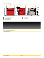
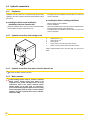
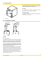
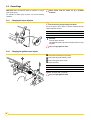
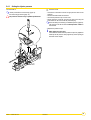
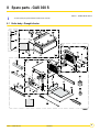
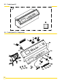
1
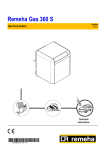
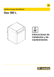
EN Gas-fired boilers GAS 360 S Installation and Service Manual 300005180-001-C Declaration of conformity 1 Declaration of conformity A.R. 8/1/2004 - BE Manufacturer Remeha B. V. Postbus 32 7300 AA APELDOORN * +31 55 5496969 + +31 55 5496969 Issued by See end of notice We hereby certify that the range of equipment specified below is in accordance with the format stated in the EC declaration of comformity, that it is manufactured and distributed in accordance with the regulations and requirements in european directives and with the regulations and requirements defined in the Royal Decree dated 8th January 2004.: Product type Floor-standing gas boiler GAS 360 S Models 8 - 10 - 12 - 14 sections Standard applied - Royal Decree dated 8th January 2004 - 90/396/EEC Gas Appliance Directive Reference Standard: EN 297 ; EN 656 ; EN 437 - 2006/95/EC Low Voltage Directive Reference Standard: EN 60.335.1 - 2004/108/EC Electromagnetic Compatibility Directive Reference Standard: EN 50.081.1 ; EN 50.082.1 ; EN 55.014 - 92/42/EEC Efficiency Directive 1 Low temperature gas boiler Inspecting organisation GWI (D-Essen) Measured values NOx: < 200 mg/kWh CO: < 15 mg/kWh Date: Signature Technical Director Mr. Bertrand Schaff 2 GAS 360 S 04/01/11 - 300005180-001-C Contents 1 Introduction . . . . . . . . . . . . . . . . . . . . . . . . . . . . . . . . . . . . . . . . . . . . . . . . . . . . . . . . . . . . . . . . . . . . . . . . . . . . .5 1.1 1.2 1.3 2 Safety instructions and recommendations. . . . . . . . . . . . . . . . . . . . . . . . . . . . . . . . . . . . . . . . . . . . . . . . . . . .6 2.1 2.2 3 Safety instructions . . . . . . . . . . . . . . . . . . . . . . . . . . . . . . . . . . . . . . . . . . . . . . . . . . . . . . . . . . . . . . . . . . . . . . . . . . . . . . . . . . . . . . .6 Recommendations . . . . . . . . . . . . . . . . . . . . . . . . . . . . . . . . . . . . . . . . . . . . . . . . . . . . . . . . . . . . . . . . . . . . . . . . . . . . . . . . . . . . . . .6 Technical description . . . . . . . . . . . . . . . . . . . . . . . . . . . . . . . . . . . . . . . . . . . . . . . . . . . . . . . . . . . . . . . . . . . . .7 3.1 3.2 3.3 3.4 4 Used symbols . . . . . . . . . . . . . . . . . . . . . . . . . . . . . . . . . . . . . . . . . . . . . . . . . . . . . . . . . . . . . . . . . . . . . . . . . . . . . . . . . . . . . . . . . . .5 General. . . . . . . . . . . . . . . . . . . . . . . . . . . . . . . . . . . . . . . . . . . . . . . . . . . . . . . . . . . . . . . . . . . . . . . . . . . . . . . . . . . . . . . . . . . . . . . .5 Homologations . . . . . . . . . . . . . . . . . . . . . . . . . . . . . . . . . . . . . . . . . . . . . . . . . . . . . . . . . . . . . . . . . . . . . . . . . . . . . . . . . . . . . . . . . .5 1.3.1 User country. . . . . . . . . . . . . . . . . . . . . . . . . . . . . . . . . . . . . . . . . . . . . . . . . . . . . . . . . . . . . . . . . . . . . . . . . . . . . . . . . . . . . .5 1.3.2 Directive 97/23/EC . . . . . . . . . . . . . . . . . . . . . . . . . . . . . . . . . . . . . . . . . . . . . . . . . . . . . . . . . . . . . . . . . . . . . . . . . . . . . . . . .5 General description . . . . . . . . . . . . . . . . . . . . . . . . . . . . . . . . . . . . . . . . . . . . . . . . . . . . . . . . . . . . . . . . . . . . . . . . . . . . . . . . . . . . . .7 Technical characteristics . . . . . . . . . . . . . . . . . . . . . . . . . . . . . . . . . . . . . . . . . . . . . . . . . . . . . . . . . . . . . . . . . . . . . . . . . . . . . . . . . .8 Main parts. . . . . . . . . . . . . . . . . . . . . . . . . . . . . . . . . . . . . . . . . . . . . . . . . . . . . . . . . . . . . . . . . . . . . . . . . . . . . . . . . . . . . . . . . . . . . .9 Operating principle . . . . . . . . . . . . . . . . . . . . . . . . . . . . . . . . . . . . . . . . . . . . . . . . . . . . . . . . . . . . . . . . . . . . . . . . . . . . . . . . . . . . . .10 Installation . . . . . . . . . . . . . . . . . . . . . . . . . . . . . . . . . . . . . . . . . . . . . . . . . . . . . . . . . . . . . . . . . . . . . . . . . . . . .12 4.1 Regulations governing installation . . . . . . . . . . . . . . . . . . . . . . . . . . . . . . . . . . . . . . . . . . . . . . . . . . . . . . . . . . . . . . . . . . . . . . . . . .12 4.1.1 France . . . . . . . . . . . . . . . . . . . . . . . . . . . . . . . . . . . . . . . . . . . . . . . . . . . . . . . . . . . . . . . . . . . . . . . . . . . . . . . . . . . . . . . . .12 4.1.2 Other countries. . . . . . . . . . . . . . . . . . . . . . . . . . . . . . . . . . . . . . . . . . . . . . . . . . . . . . . . . . . . . . . . . . . . . . . . . . . . . . . . . . .12 4.2 Package list . . . . . . . . . . . . . . . . . . . . . . . . . . . . . . . . . . . . . . . . . . . . . . . . . . . . . . . . . . . . . . . . . . . . . . . . . . . . . . . . . . . . . . . . . . .12 4.3 Mounting. . . . . . . . . . . . . . . . . . . . . . . . . . . . . . . . . . . . . . . . . . . . . . . . . . . . . . . . . . . . . . . . . . . . . . . . . . . . . . . . . . . . . . . . . . . . . .13 4.3.1 Position of the boiler. . . . . . . . . . . . . . . . . . . . . . . . . . . . . . . . . . . . . . . . . . . . . . . . . . . . . . . . . . . . . . . . . . . . . . . . . . . . . . .13 4.3.2 Ventilation . . . . . . . . . . . . . . . . . . . . . . . . . . . . . . . . . . . . . . . . . . . . . . . . . . . . . . . . . . . . . . . . . . . . . . . . . . . . . . . . . . . . . .14 4.3.3 Main dimensions . . . . . . . . . . . . . . . . . . . . . . . . . . . . . . . . . . . . . . . . . . . . . . . . . . . . . . . . . . . . . . . . . . . . . . . . . . . . . . . . .15 4.3.4 Assembling the appliance . . . . . . . . . . . . . . . . . . . . . . . . . . . . . . . . . . . . . . . . . . . . . . . . . . . . . . . . . . . . . . . . . . . . . . . . . .15 4.4 Hydraulic connections . . . . . . . . . . . . . . . . . . . . . . . . . . . . . . . . . . . . . . . . . . . . . . . . . . . . . . . . . . . . . . . . . . . . . . . . . . . . . . . . . . .16 4.4.1 Regulations . . . . . . . . . . . . . . . . . . . . . . . . . . . . . . . . . . . . . . . . . . . . . . . . . . . . . . . . . . . . . . . . . . . . . . . . . . . . . . . . . . . . .16 4.4.2 Hydraulic connection of the heating circuit. . . . . . . . . . . . . . . . . . . . . . . . . . . . . . . . . . . . . . . . . . . . . . . . . . . . . . . . . . . . . .16 4.4.3 Hydraulic connection of the water circuit for domestic use . . . . . . . . . . . . . . . . . . . . . . . . . . . . . . . . . . . . . . . . . . . . . . . . .16 4.4.4 Water treatment . . . . . . . . . . . . . . . . . . . . . . . . . . . . . . . . . . . . . . . . . . . . . . . . . . . . . . . . . . . . . . . . . . . . . . . . . . . . . . . . . .16 4.5 Gas connection. . . . . . . . . . . . . . . . . . . . . . . . . . . . . . . . . . . . . . . . . . . . . . . . . . . . . . . . . . . . . . . . . . . . . . . . . . . . . . . . . . . . . . . . .17 4.6 Connection to a chimney . . . . . . . . . . . . . . . . . . . . . . . . . . . . . . . . . . . . . . . . . . . . . . . . . . . . . . . . . . . . . . . . . . . . . . . . . . . . . . . . .17 4.7 Electrical connections. . . . . . . . . . . . . . . . . . . . . . . . . . . . . . . . . . . . . . . . . . . . . . . . . . . . . . . . . . . . . . . . . . . . . . . . . . . . . . . . . . . .18 4.8 Skeleton Diagrams . . . . . . . . . . . . . . . . . . . . . . . . . . . . . . . . . . . . . . . . . . . . . . . . . . . . . . . . . . . . . . . . . . . . . . . . . . . . . . . . . . . . . .18 5 Start-up. . . . . . . . . . . . . . . . . . . . . . . . . . . . . . . . . . . . . . . . . . . . . . . . . . . . . . . . . . . . . . . . . . . . . . . . . . . . . . . .19 5.1 5.2 5.3 5.4 Control panel . . . . . . . . . . . . . . . . . . . . . . . . . . . . . . . . . . . . . . . . . . . . . . . . . . . . . . . . . . . . . . . . . . . . . . . . . . . . . . . . . . . . . . . . . .19 Check points before commissioning. . . . . . . . . . . . . . . . . . . . . . . . . . . . . . . . . . . . . . . . . . . . . . . . . . . . . . . . . . . . . . . . . . . . . . . . .19 Commissioning procedure . . . . . . . . . . . . . . . . . . . . . . . . . . . . . . . . . . . . . . . . . . . . . . . . . . . . . . . . . . . . . . . . . . . . . . . . . . . . . . . .19 Gas settings . . . . . . . . . . . . . . . . . . . . . . . . . . . . . . . . . . . . . . . . . . . . . . . . . . . . . . . . . . . . . . . . . . . . . . . . . . . . . . . . . . . . . . . . . . .20 5.4.1 Changing the burner injectors . . . . . . . . . . . . . . . . . . . . . . . . . . . . . . . . . . . . . . . . . . . . . . . . . . . . . . . . . . . . . . . . . . . . . . .20 5.4.2 Changing the ignition burner injector . . . . . . . . . . . . . . . . . . . . . . . . . . . . . . . . . . . . . . . . . . . . . . . . . . . . . . . . . . . . . . . . . .20 5.4.3 Setting the injector pressure . . . . . . . . . . . . . . . . . . . . . . . . . . . . . . . . . . . . . . . . . . . . . . . . . . . . . . . . . . . . . . . . . . . . . . . .21 5.4.4 Setting the start up pressure . . . . . . . . . . . . . . . . . . . . . . . . . . . . . . . . . . . . . . . . . . . . . . . . . . . . . . . . . . . . . . . . . . . . . . . .22 5.4.5 Attaching the label . . . . . . . . . . . . . . . . . . . . . . . . . . . . . . . . . . . . . . . . . . . . . . . . . . . . . . . . . . . . . . . . . . . . . . . . . . . . . . . .22 5.4.6 Pressure setting and marking of calibrated injectors . . . . . . . . . . . . . . . . . . . . . . . . . . . . . . . . . . . . . . . . . . . . . . . . . . . . . .23 5.5 Checks and adjustments after commissioning . . . . . . . . . . . . . . . . . . . . . . . . . . . . . . . . . . . . . . . . . . . . . . . . . . . . . . . . . . . . . . . . .23 5.6 Changing the settings. . . . . . . . . . . . . . . . . . . . . . . . . . . . . . . . . . . . . . . . . . . . . . . . . . . . . . . . . . . . . . . . . . . . . . . . . . . . . . . . . . . .23 6 Stopping the boiler . . . . . . . . . . . . . . . . . . . . . . . . . . . . . . . . . . . . . . . . . . . . . . . . . . . . . . . . . . . . . . . . . . . . . .24 6.1 6.2 Precautions to take if there is a danger of frost . . . . . . . . . . . . . . . . . . . . . . . . . . . . . . . . . . . . . . . . . . . . . . . . . . . . . . . . . . . . . . . .24 Precautions to take in the event of prolonged shutdown (one year or more) . . . . . . . . . . . . . . . . . . . . . . . . . . . . . . . . . . . . . . . . . .24 04/01/11 - 300005180-001-C GAS 360 S 3 7 Checking and maintenance . . . . . . . . . . . . . . . . . . . . . . . . . . . . . . . . . . . . . . . . . . . . . . . . . . . . . . . . . . . . . . .25 7.1 Checks . . . . . . . . . . . . . . . . . . . . . . . . . . . . . . . . . . . . . . . . . . . . . . . . . . . . . . . . . . . . . . . . . . . . . . . . . . . . . . . . . . . . . . . . . . . . . . .25 7.1.1 Checking the ignition burner . . . . . . . . . . . . . . . . . . . . . . . . . . . . . . . . . . . . . . . . . . . . . . . . . . . . . . . . . . . . . . . . . . . . . . . .25 7.1.2 Safety devices . . . . . . . . . . . . . . . . . . . . . . . . . . . . . . . . . . . . . . . . . . . . . . . . . . . . . . . . . . . . . . . . . . . . . . . . . . . . . . . . . . .25 7.1.3 Water level . . . . . . . . . . . . . . . . . . . . . . . . . . . . . . . . . . . . . . . . . . . . . . . . . . . . . . . . . . . . . . . . . . . . . . . . . . . . . . . . . . . . . .25 7.1.4 Checking burner safety . . . . . . . . . . . . . . . . . . . . . . . . . . . . . . . . . . . . . . . . . . . . . . . . . . . . . . . . . . . . . . . . . . . . . . . . . . . .26 7.1.5 Checking the safety thermostat . . . . . . . . . . . . . . . . . . . . . . . . . . . . . . . . . . . . . . . . . . . . . . . . . . . . . . . . . . . . . . . . . . . . . .26 7.1.6 Checking the downdraught thermostat . . . . . . . . . . . . . . . . . . . . . . . . . . . . . . . . . . . . . . . . . . . . . . . . . . . . . . . . . . . . . . . .26 7.2 Maintenance . . . . . . . . . . . . . . . . . . . . . . . . . . . . . . . . . . . . . . . . . . . . . . . . . . . . . . . . . . . . . . . . . . . . . . . . . . . . . . . . . . . . . . . . . . .27 7.2.1 Cleaning main burner and ignition burner . . . . . . . . . . . . . . . . . . . . . . . . . . . . . . . . . . . . . . . . . . . . . . . . . . . . . . . . . . . . . .27 7.2.2 Cleaning of the heating body . . . . . . . . . . . . . . . . . . . . . . . . . . . . . . . . . . . . . . . . . . . . . . . . . . . . . . . . . . . . . . . . . . . . . . . .28 7.2.3 Cleaning painted surfaces . . . . . . . . . . . . . . . . . . . . . . . . . . . . . . . . . . . . . . . . . . . . . . . . . . . . . . . . . . . . . . . . . . . . . . . . . .28 7.3 Troubleshooting . . . . . . . . . . . . . . . . . . . . . . . . . . . . . . . . . . . . . . . . . . . . . . . . . . . . . . . . . . . . . . . . . . . . . . . . . . . . . . . . . . . . . . . .29 7.3.1 Error messages . . . . . . . . . . . . . . . . . . . . . . . . . . . . . . . . . . . . . . . . . . . . . . . . . . . . . . . . . . . . . . . . . . . . . . . . . . . . . . . . . .29 7.3.2 Incidents and solutions. . . . . . . . . . . . . . . . . . . . . . . . . . . . . . . . . . . . . . . . . . . . . . . . . . . . . . . . . . . . . . . . . . . . . . . . . . . . .29 8 Spare parts - GAS 360 S . . . . . . . . . . . . . . . . . . . . . . . . . . . . . . . . . . . . . . . . . . . . . . . . . . . . . . . . . . . . . . . . . .31 8.1 8.2 Boiler body + Draught diverter . . . . . . . . . . . . . . . . . . . . . . . . . . . . . . . . . . . . . . . . . . . . . . . . . . . . . . . . . . . . . . . . . . . . . . . . . . . . .31 Gas line . . . . . . . . . . . . . . . . . . . . . . . . . . . . . . . . . . . . . . . . . . . . . . . . . . . . . . . . . . . . . . . . . . . . . . . . . . . . . . . . . . . . . . . . . . . . . .32 8.2.1 8-10-12 sections. . . . . . . . . . . . . . . . . . . . . . . . . . . . . . . . . . . . . . . . . . . . . . . . . . . . . . . . . . . . . . . . . . . . . . . . . . . . . . . . . .32 8.2.2 14 sections . . . . . . . . . . . . . . . . . . . . . . . . . . . . . . . . . . . . . . . . . . . . . . . . . . . . . . . . . . . . . . . . . . . . . . . . . . . . . . . . . . . . . .33 8.3 Control panel K. . . . . . . . . . . . . . . . . . . . . . . . . . . . . . . . . . . . . . . . . . . . . . . . . . . . . . . . . . . . . . . . . . . . . . . . . . . . . . . . . . . . . . . . .34 8.4 Control panel K + Components . . . . . . . . . . . . . . . . . . . . . . . . . . . . . . . . . . . . . . . . . . . . . . . . . . . . . . . . . . . . . . . . . . . . . . . . . . . .34 8.5 Metal casing for control panel K . . . . . . . . . . . . . . . . . . . . . . . . . . . . . . . . . . . . . . . . . . . . . . . . . . . . . . . . . . . . . . . . . . . . . . . . . . . .35 8.6 Boiler body insulation . . . . . . . . . . . . . . . . . . . . . . . . . . . . . . . . . . . . . . . . . . . . . . . . . . . . . . . . . . . . . . . . . . . . . . . . . . . . . . . . . . . .35 8.7 Casing . . . . . . . . . . . . . . . . . . . . . . . . . . . . . . . . . . . . . . . . . . . . . . . . . . . . . . . . . . . . . . . . . . . . . . . . . . . . . . . . . . . . . . . . . . . . . . .36 4 GAS 360 S 04/01/11 - 300005180-001-C 1 Introduction 1.1 Used symbols Caution danger Reference Risk ZRefer of injury and damage to equipment. Attention must be to another manual or other pages in this instruction paid to the warnings on safety of persons and equipment. manual. DHW: Domestic hot water Specific information Information must be kept in mind to maintain comfort. 1.2 General Congratulations on your choice of a high quality product. We strongly advise you to read the following instructions in order to guarantee the optimal operation of your appliance. We are sure that it will be entirely to your satisfaction and will meet with all of your expectations. ` Keep these instructions in a safe place close to the appliance. ` For a proper operating of the boiler, follow carefully the instructions. ` The manufacturer is not liable for any improper use of the appliance or failure to maintain or install the unit correctly (the user shall take care to ensure that the system is installed by a qualified engineer). ` In the interest of customers, De Dietrich Thermique SAS are continuously endeavouring to make improvements in product quality. All the specifications stated in this document are therefore subject to change without notice. 1.3 Homologations CE identification no: CE-0085AU0115 France: Performance class III boiler according to ATG B 84 recommendations. 8 sections: Type B11BS boiler 10-14 sections: Type B11 boiler 1.3.1 User country User country ES, GB HU 1.3.2 Gas category II2H3P II2H3P Gas type Connection pressure (mbar) G20 20 G31 37 G20 25 G31 50 Remeha Gas 360 S boilers are delivered preset for operation on group H natural gases. For operation on another gas group, see the chapter "Gas Zsettings" (Page: 20). Directive 97/23/EC Gas and oil boilers with a maximum operating temperature of 110°C and hot water tanks with a maximum operating pressure of 10 bar pertain to article 3.3 of the directive, and therefore, cannot be CEmarked to certify compliance with the directive 97/23 EC. Compliance of Remeha boilers and DHW tanks with the codes of practice, required by article 3.3 of directive 97/23/EEC, is certified by the CE marking relative to directives 90/396/EEC, 92/42/EEC, 2006/ 95/EC and 2004/108/EC. 04/01/11 - 300005180-001-C GAS 360 S 5 2 Safety instructions and recommendations 2.1 Safety instructions Fire hazard Risk of being burnt Do not stock products of an inflammable nature close to the Avoid direct contact with the flame viewport. appliance. Depending on the settings of the appliance: If you smell gas, do not use a naked flame, do not smoke, do not operate electrical contacts or switches (doorbell, - The temperature of the flue gas conduits may exceed 60°C - The temperature of the radiators may reach 95°C - The temperature of the domestic hot water may reach 65°C lights, motor, lift, etc.). 1.Isolate the gas supply 2.Open the windows 3.Extinguish all flames 4.Evacuate the premises 5.Contact a qualified professional 6.Inform the gas supplier Risk of damage Do not stock chloride or fluoride compounds close to the appliance. Install the appliance in frost-free premises. Risk of intoxication Do not obstruct the air inlets in the room (even partially). If you smell flue gases 1.Switch the appliance off Do not neglect to service the appliance: Contact a qualified professional or take out a maintenance contract for the annual servicing of the appliance. 2.Open the windows 3.Evacuate the premises 4.Contact a qualified professional 2.2 Recommendations Only qualified professionals are authorised to work on the appliance and the instalation. Before any work, switch off the mains supply to the appliance. Check regularly that the installation contains water and is pressurised. Keep the appliance accessible at all times. Avoid draining the installation. The appliance should be on Summer or Antrifreeze mode rather than switched off to guarantee the following functions: - Frost protection - Protection against corrosion on domestic hot water tanks fitted with a titanium anode 6 GAS 360 S 04/01/11 - 300005180-001-C 3 Technical description 3.1 General description Boilers in the GAS 360 S range have the following characteristics: - Cast iron floor-standing gas boiler. Connecting to a chimney. Atmospheric burner (2 stages). Heating body in cast iron with overlapping studs making it possible to obtain extremely high efficiency. Also, the baffling in the smoke circuits limits the natural chimney effect and gives high performance yields. - Efficient insulation of the entire boiler unit for very low losses to the ambient air. The figure given after Remeha Gas 360 S indicates the number of sections which make up the boiler. For example: Remeha Gas 360 S/8: 8 section boilers 04/01/11 - 300005180-001-C GAS 360 S 7 3.2 Technical characteristics Models Gas 360 S/ Useful output Power input 8 Smoke temperature 14 kW 36 45 54 54 Stage2 kW 63 81 99 117 Stage1 kW 39.4 49.1 58.8 58.8 Stage2 kW 68.9 88.4 107.8 127.2 8 10 12 14 Stage1 Kg/h 140 166 199 199 Stage2 Kg/h 138 177 216 255 °C 135 135 135 135 % 7.4 7.4 7.4 7.4 µA 3 3 3 3 0.04 0.04 0.04 0.04 (1) (2) CO2 (Natural gas H) (1) Ionization current 12 Stage1 Number of sections Mass flue gas flow rate (1) (2) 10 (1) Required depressurisation at the nozzle (1) mbar Minimum output temperature °C 30 30 30 30 Maximum output temperature °C 90 90 90 90 Maximum operating pressure bar 6 6 6 6 Electrical connection V/Hz 230/50 230/50 230/50 230/50 Electrical power (1) (3) W 25 25 25 25 Gas connection inch R1 R1 R1 R1 Heating connection inch R1 1/2 R1 1/2 R1 1/2 R1 1/2 Internal diameter flue gas nozzle mm 180 200 200 225 ∆T= 10K mbar 56 120 216 320 ∆T= 15K mbar 25 53 96 142 ∆T= 20K mbar 14 30 54 80 Loss of load hydraulic circuit (1) Water content l 32.6 39.8 47 54.2 Net weight (without water) kg 257 305 357 408 (1) (2) (3) At nominal output (Stage2) Boiler temperature: 80 °C Electrical power of the boiler only with no accessories Conditions of use: - 8 Max. safety temperature: 110 °C Max. operating pressure: 6 bar Thermostat adjustable from 30 to 90°C Safety thermostat: 110 °C GAS 360 S 04/01/11 - 300005180-001-C 3.3 Main parts 8 sections 10-14 sections 2 7 8 9 10 11 1 6 3a 3b 4b 8502N169A 4a 5a 5b 11. Factory fitted bridge Connection for cyclical tightness controller (Option - Package RD18) 1. Control panel The control panel gives priority to producing domestic hot water 2. Factory fitted bridge Connection for gas pressure switch Natural gas: 12.5 mbar Propane: 20 mbar 3. a: Gas valve - Stage1 - Type VK4100C1026 b: Gas valve - Stage2 - Type VK4105C1066 (8-12 sections) Type VR4605CB1033 (14 sections) 4. a: Flame inspection window - Stage1 b: Flame inspection window - Stage2 5. Complete ignition burner a: Ignition electrode: This ensures ignition burner ignition using a high voltage spark. b: Ionization probe: This detects the presence of a burner ignition flame through ionization. 6. Safety box: The safety control box manages and checks the boiler's ignition, operating and shutdown sequences. Type Honeywell S 4565 BF 1161. After resetting, the safety control box remains on standby for around 1 minute. 7. Valve connector - Stage2 8. Safety control box and valve connector - Stage1 9. Downdraught thermostat: The downdraught thermostat located in the draught diverter cuts off the gas supply and puts the boiler into safety shutdown in the event of flue gas blow back 8 sections: Supplied 10-14 sections: Option (Factory fitted bridge) - Package RD19 10. Factory fitted bridge: Not used 04/01/11 - 300005180-001-C GAS 360 S 9 3.4 Operating principle S4565 BF 1161 safety box The ignition and burner surveillance sequences are ensured by the safety box. Normal operating cycle If heating is required, the boiler thermostat TCH 1 closes the contact. The ignition transformer TA integrated into the safety control box and the safety flap on the gas valve (supplying the ignition burner) are switched on. Gas from the ignition burner is ignited by the ignition electrode and within the time interval ts; a minimum current of 0.9 µA appears on the ionization sensor SF and the gas valve regulation flap (supplying the principal burner) opens. If, moreover, TCH2 is required, the 2nd stage valve VP2 opens. Operating cycle on safety (start up without flame signal) - If the flame is not detected before the end of the safety time ts, the safety control box goes into safety lockout and the safety lockout warning light comes on. To restart the heater, press the reset button on the safety box. - If there is a loss of flame in normal operation, the box automatically repeats the start up sequence. - If a flame is present before start-up, the safety control box remains on standby. 10 GAS 360 S 04/01/11 - 300005180-001-C Resetting The box is reset after going into safety by pressing the reset button. If the reset button does not work, wait at least 15 seconds before trying a second time. After activating the reset button, the warning light goes out and the safety control box restarts after a waiting time of around 1 minute. Legend A Heat demand - 1st/2nd stage B Formation of flame in ignition burner C Heat demand - 1st stage D On safety through absence of flame signal Press the reset button The box may be on safety on its first start up: press the reset button to release it. E If the reset button is pressed in normal operation, the gas valves close and the box starts a new ignition sequence. TA Ignition transformer SF Burner flame signal TCH1Stage 1 boiler thermostat TCH2Stage 2 boiler thermostat VA Safety lockout warning light VBa Ignition burner valve VP1 Main burner valve - 1st stage VP2 Main burner valve - 2nd stage t3n Flame stabilisation time: Wait 3 seconds tr Restart waiting time: 1 minutes ts Safety time: 55 s max tva Alarm time: 15 seconds 04/01/11 - 300005180-001-C tw Waiting time: 0 seconds tc Auto-control time: 1.5 seconds Box output signals GAS 360 S Required input signals 11 4 Installation 4.1 Regulations governing installation 4.1.1 France Residential buildings For all appliances: Statutory terms and conditions of installation and maintenance: The installation and maintenance of the appliance must be carried out by a qualified professional in compliance with the statutory texts of the codes of conduct in force, particularly: - Order of 27 April 2009 amending the Order of 2 August 1977 Technical and safety rules applicable to combustible gas and liquefied hydrocarbon installations situated inside residential buildings and their annexes. - NF P 45-204 standards Gas installation, (formerly DTU 61-1, gas installations: April 1982, addendum no 1: July 1984). - Local Sanitary Regulations For appliances connected to the electricity network: - NF C 15-100 standards Low voltage electrical installation - Rules.. - Articles GZ - Installations operating on combustible gases and liquefied hydrocarbons. Then, depending on use: - Articles CH-Heating, ventilation, refrigeration, air conditioning and production of steam and domestic hot water. b. Instructions specific to each type of establishment open to the public (hospitals, stores, etc.). Certificate of compliance In application of Article 25 of the Order of 27 April 2009 amending the Order of 2 August 1977 amended and Article 1 of the amended Order of 05/02/1999, the installer is required to draw up certificates of conformity approved by the Ministers responsible for construction and gas safety: - Different forms (forms 1, 2 or 3) for a new gas installation. - "Model 4" in particular after replacing a furnace with a new one. Establishments open to the public Statutory terms and conditions of installation: The installation and maintenance of the appliance must be carried out in compliance with the statutory texts and rules of the codes of conduct in force, particularly: - Safety regulations against fire and panic in establishments open to the public: a. General regulations 4.1.2 Other countries Installation and maintenance of the boiler must be carried out by a qualified professional in compliance with prevailing local and national regulations. 4.2 Package list ZAssembly Instructions 12 GAS 360 S 04/01/11 - 300005180-001-C 4.3 Mounting 4.3.1 Position of the boiler - The dimensions (in mm) correspond to the minimum recommended dimensions needed to ensure adequate accessibility around the boiler. - Dimensions a and b correspond to the dimensions to be respected to ensure clearance of the assembly tool (simplified JD or JD-TE Plus) - delivery body not assembled. if a = 1400 mm ; b = 500 mm 930 b 50 0 if a = 500 mm ; b = 1400 mm to store inflammable products and materials inIt istheforbidden boiler room or close to the boiler, even temporarily. A safety distance of at least 2 metres should be respected. A B 70 0 Gas 360 S/ a 8 10 12 14 A (mm) 846 1113 1280 1447 B (mm) 952 1007 1007 1007 04/01/11 - 300005180-001-C GAS 360 S 13 4.3.2 Ventilation Caution: In order to avoid damage to the boiler, it is necessary to prevent the contamination of combustion air by chlorine and/or fluoride compounds, which are particularly corrosive. These compounds are present, for example, in aerosol sprays, paints, solvents, cleaning products, washing products, detergents, glues, snow clearing salts, etc. Therefore: - Do not pull in air evacuated from premises using such products: hairdressing salons, dry cleaners, industrial premises (solvents), premises containing refrigeration systems (risk of refrigerant leakage), etc. - Do not stock such products close to the boilers. If the boiler and/or peripheral equipment are corroded by such chloride or fluoride compounds, the contractual guarantee cannot be applied. France Direct air inlet: • • Boiler with nominal output between 25 and 70 kW in accordance with DTU 61.1 (NF P 45-204). In the case of a direct air inlet, the compulsory cross section of the air vent must be of a minimum surface area of 70 cm2. Boiler with nominal output greater than 70 kW in accordance with DTU 65.4 (NF P 52-221). Upper and lower air vents compulsory. - Upper air vents: Cross section equal to half the total cross section of the flue gas pipes with a minimum of 2.5 dm2. - Lower air vents: ,86PDirect air inlet: S ( dm 2 ) ≥ 0------------P = Installed power in kW 20 A The combustive air must reach the burner from the front. The location of air inlets in relation to the high ventilation openings shall ensure that the air is renewed in the entire volume of the boiler room. Please refer to the prevailing regulations in your country. 14 GAS 360 S 04/01/11 - 300005180-001-C 4.3.3 Main dimensions Connection for safety valves Rp 1 Heating outlet R 1 1/2 Draining Rp 3/4 Gas inlet R 1 Heating return R 1 1/2 DTG 230-... S 8 10 12 14 A 946 1113 1280 1447 B 952 1007 1007 1007 C 102 124 124 124 E 75 75 75 75 F 494 578 661 745 ØG 180 200 200 225 R: Tapped connection 4.3.4 Rp: Thread Assembling the appliance ZAssembly Instructions 04/01/11 - 300005180-001-C GAS 360 S 15 4.4 Hydraulic connections 4.4.1 Regulations Installation must be carried out in accordance with the prevailing regulations, the codes of practice and the recommendations in these instructions. Installing the boiler in new installations (installations less than 6 months old) - Clean the installation with a universal cleaner to eliminate debris from the appliance (copper, flaxen thread, flux). 4.4.2 - Thoroughly flush the installation until the water runs clear and shows no impurities. Installing the boiler in existing installations - Remove sludge from the installation. - Flush the installation. - Clean the installation with a universal cleaner to eliminate debris from the appliance (copper, flaxen thread, flux). - Thoroughly flush the installation until the water runs clear and shows no impurities. Hydraulic connection of the heating circuit H I K L Heating outlet R1 1/2 (1) Heating return R1 1/2 (1) Draining Rp 3/4 Auxiliary outlet or connection of the safety valve Rp1 (1) Welded connection possible after sawing off the threading. Install a sludge decanting pot on the return pipe, very close to the boiler. A0 4.4.3 50 00 2 Hydraulic connection of the water circuit for domestic use ZDomestic hot water calorifier instructions 4.4.4 Water treatment Central heating systems must be cleaned to eliminate debris (copper, strands, brazing flux) linked to the installation of the system and deposits that can cause malfunctions (noise in the system, chemical reaction between metals). On the other hand, it is important to protect central heating systems against corrosion, scaling and microbiological growth by using a corrosion inhibitor adapted to all types of systems (steel, cast iron radiators, heated floor, PER) 16 GAS 360 S 04/01/11 - 300005180-001-C 4.5 Gas connection It is necessary to abide by the prevailing instructions and regulations. Each time, a blocking tap will be located as near as possible to the heater. A gas filter must be fitted to the boiler inlet. France Pipe diameters must be defined in accordance with ATG's (Association Technique de Gaz) B171 specifications. Other countries The diameters of the pipes must be defined in accordance with the standards in force in your country. A0 J 50 00 3 Gas inlet R1 4.6 Connection to a chimney A 1 Good A 40 mm (minimum) 2 Poor The appliance must be installed in accordance with the Codes of Practice using a leak proof pipe made of a material capable of withstanding hot combustion gases and any acidic condensation. The pipe must be laid out to allow any likely condensation to drain. It must be in accordance with existing regulations for pipes used for this purpose. Standard meshed connection pipes are to be avoided. The pipe connecting the outlet conduit must also be as short as possible and without a reduced diameter. The vertical section of the draught diverter outlet must be a minimum length 3x the diameter of the nozzle before an elbow joint is fitted. The pipe must have a diameter not less than the heater's nozzle diameter along its whole length. This pipe must be able to be easily disassembled and must not have a sudden change in diameter. The outlet conduit must be maintained in a good condition, checked and cleaned at least once a year. 04/01/11 - 300005180-001-C GAS 360 S 17 4.7 Electrical connections Only qualified professionnals may carry out electrical connections, always with the power off. Rules to be respected Make the electrical connections of the appliance according to: - Power the appliance via a circuit which includes a remote omnipolar switch with a gap of more than 3 mm. - Connect all of the cables to the terminal blocks in the control panel. - the instructions of the prevailing standards, - the instructions on the circuit diagrams provided with the appliance, - the recommendations in the instructions. The available output per outlet is 450 W (2 A, with cos ϕ = 0.7) and the inrush current must be lower than 16 A. Do not modify the connections inside the control panel. Keep to the polarity shown on the terminals: phase (L), neutral (N) and earth 4. If the charge exceeds one of these values, relay the command using a contactor (fitted outside the control panel). Standards to be respected France: Electrical connections must be in compliance with the NF C 15.100 standard. Other countries: The electrical connections shall comply with standards in force. Separate the sensor cables from the 230 V cables. Outside the boiler : Use 2 pipes or cable guides at least 10 cm apart. For the 230 V electrical connections, use 3-wire cables with a crosssection of 0.75 mm². For other electrical connections, use the 3 wire cable with a diameter of 0.75 mm². Make the electrical connections: ZControl panel instructions. ZOptions brochure. 4.8 Skeleton Diagrams Z Control panel instructions 18 GAS 360 S 04/01/11 - 300005180-001-C 5 Start-up Initial commissioning professional. must be done by a qualified 5.1 Control panel ZControl panel instructions 5.2 Check points before commissioning Hydraulic circuit - Check that the installation and boiler are adequately filled with water and correctly irrigated and bled. - Check that there are no leaks on the hydraulic connections. Gas circuit - Check that the appliance is properly set for the type of gas used. If this is not the case: Gas settings (Page: 20) Z - Check the supply pressure. - Check the nozzle pressure and the start-up pressure. Pressure setting and marking of calibrated injectors (page: 23) Z - If necessary, adjust the pressures Setting the injector pressure (page: 21) Setting the start up pressure (page: 22) Z Electrical connectors - Check that the connectors under the control panel are correctly fitted. 5.3 Commissioning procedure Initial commissioning professional. must be done by a qualified 4. Turn the burner switch to 2 (2 stage version) 1. Check the water pressure in the installation several times a year. Top up with more water if necessary. 5. Check that the safety thermostat has not triggered. Remove the safety thermostat hood and press the reset button with a screwdriver. 2. Open the gas valve. 6. Set the On/Off switch to 1. 3. Make the settings on the control panel. 04/01/11 - 300005180-001-C GAS 360 S 19 5.4 Gas settings GAS 360 S boilers are delivered preset for operation on natural gases of H/E groups. These actions technician. must be carried out by a qualified For operation on another group of gases, carry out the following operations. 5.4.1 Changing the burner injectors Cut the electricity and gas supply to the boiler. Lift out the injector with a number 12 spanner assemble the new injectors with their new joint. Nozzle marking Natural gas H 257B Propane 160B Assembly: Correctly replace the seals. First tighten the injectors by hand and carefully lock them using a spanner. Carry out a gas tightness check. 5.4.2 Changing the ignition burner injector Unscrew the connecting nut (14 spanner) Pull the gas supply pipe towards yourself Take out the ignition burner nozzle Fit the new nozzle 4 Nozzle marking 3 Natural gas H 40 Propane 30 Re-attach the supply tube (14 spanner) Carry out a gas tightness check. 1 20 GAS 360 S 04/01/11 - 300005180-001-C 5.4.3 Setting the injector pressure Turn the boiler on. .Check points before commissioning (page: 19) ZCommissioning procedure (page: 19) The pressure must be set by a qualified professional. Pressure socket - Connect the manometer to the left or right pressure outlet on the manifold. - Set the boiler thermostats to maximum. - Unscrew the protection cap on each valve. - Set the pressure on the left valve and the right valve using the screw which can be found under the protective plug. Pressure setting and marking of calibrated injectors (page:23) The pressure must be the same on both pressure outlets on the manifold. Z - Replace the protection caps. When replacing a gas valve: Check that the screw under the protection cap is fully tightened. Carefully set the pressure and progressivity at the opening as described in this chapter. 04/01/11 - 300005180-001-C GAS 360 S 21 5.4.4 Setting the start up pressure Right valve Left valve The progressivity of the left valve (2nd stage) is always set to "Minimum" (8-12 sections). No setting is needed on the left valve on a 14-element boiler. Operation of the progressivity screw setting 1 2 1/4 turn Natural gas Propane If necessary, the start-up pressure can be set on the right valve (1st stage) using a flat screwdriver. In the factory, it is set to maximum. To modify this setting, it necessary first to remove the protection using a screwdriver (1/4 turn). Natural gas H Propane 5.4.5 Start-up pressure Recommended position 11 mbar max 10 mbar C (1/4 turn) 8502N211 Pressure (mbar) Time (s) Attaching the label Affix the label which indicates for which type of gas the boiler is fitted and set. 22 GAS 360 S 04/01/11 - 300005180-001-C 5.4.6 Pressure setting and marking of calibrated injectors Boilers Gas 360 S/ 8 10 12 14 Nozzle pressure (1st stage + 2nd stage) Natural gas H mbar 14 14 14 14 Propane mbar 36 36 36 36 Natural gas H mbar 11 11 11 11 Propane mbar 10 10 10 10 Start-up pressure Nozzle Number of nozzles 7 9 11 13 Natural gas H/E 257B 257B 257B 257B Propane 160B 160B 160B 160B m3/h(1) 7.29 9.35 11.41 13.46 Kg/h 5.35 6.87 8.37 9.88 Gas flow rate - Stage2 Natural gas H Propane (1) 15 °C - 1013 mbar 5.5 Checks and adjustments after commissioning Carry out all the checks mentioned in the chapter "Checking Zand maintenance" (Page: 25). 5.6 Changing the settings Z Control panel instructions 04/01/11 - 300005180-001-C GAS 360 S 23 6 Stopping the boiler Set the On/Off switch to 7. 6.1 Precautions to take if there is a danger of frost Heating circuit: Use a correctly dosed antifreeze to prevent the heating water freezing. If this cannot be done, drain the system completely. In all cases, consult the fitter. Domestic hot water circuit: Drain the domestic water tank and pipes. 6.2 Precautions to take in the event of prolonged shutdown (one year or more) - Close the gas valve - The boiler and the chimney must be swept carefully. - Close the door of the boiler to prevent the internal circulation of air. 24 GAS 360 S 04/01/11 - 300005180-001-C 7 Checking and maintenance 7.1 Checks Make the following checks at least 1 time a year: - Checking the ignition burner Safety devices Water level Checking burner safety Checking the safety thermostat Checking the downdraught thermostat 7.1.1 Checking the ignition burner Check the position of the ionization probe 1, the ignition electrode gap 2 and the position of the flame diffuser 3 in terms of the sizes indicated on the drawing (required in the event of heater malfunction). 7.1.2 Safety devices Check the safety devices (particularly the valve or safety unit), referring to the instructions provided with these components. 7.1.3 Water level Regularly check the level of water in the installation. Top it up, if need be, avoiding the abrupt input of cold water into the hot boiler. If this operation is repeated several times per season, locate the leak and repair it. Do not drain the installation, except in cases of absolute necessity. For example: Several months' absence with the risk of ice in the building. 04/01/11 - 300005180-001-C GAS 360 S 25 7.1.4 Checking burner safety Close the gas valve. Check the reaction of the safety system. (Safety box on safety because of ionization fault). 7.1.5 Checking the safety thermostat Turn the 3 position switch to TEST STB. The burner starts regardless of the setting. Keep the switch in this position until the safety thermostat cuts (110ºC). To restart the heater, press the safety thermostat reset button and repeat the starting operations. 7.1.6 Checking the downdraught thermostat In the event that flue gases overflow via the draught diverter, the antioverflow safety system cuts off the electricity supply to the valve and the boiler goes into safety shutdown. Check that the anti-overflow system is working correctly on commissioning for the first time and during annual servicing of the boiler. Checking procedure Only a qualified professional may carry out the check. Ensure correct ventilation in the premises during the check. - Turn of the heater and take out the smoke duct linking the heater to the chimney. Block the boiler flue gas nozzle using a metal plate (or other heat-resistant material). - On start up, combustion products are evacuated to the back of the heater by the anti-blowback device opening inside. - The downdraught thermostat is tripped after a few moments and cuts the mains supply to the gas valve. The burner goes out. - After checking, re-assemble the smoke duct connecting the heater to the chimney. Wait for around 5 minutes (thermostat cooling time) and press the reset button on the safety control box. 26 GAS 360 S 04/01/11 - 300005180-001-C 7.2 Maintenance Carry out the following maintenance at least 1 time a year: - Cleaning main burner and ignition burner - Cleaning of the heating body - Cleaning painted surfaces 7.2.1 Cleaning main burner and ignition burner 1 2 Cut the electricity and gas supply to the boiler. Main burner Clean the burner trains (slits) using a soft brush, a shorthandled brush or a vacuum cleaner. Do not use a metal brush. On reassembly, replace the burner earth wire fixed to the right holding nut on the burner drawer. Ignition burner Clean the filter and the ignition burner injector. Remove ionization probe 1 and the earth electrode 2 deposits (for example using sand paper). Carry out a gas tightness check. 04/01/11 - 300005180-001-C GAS 360 S 27 7.2.2 Cleaning of the heating body The extent of clogging on the heating body must be checked once a year. If it is necessary to sweep the boiler, remove the burner drawer to prevent deposits and soot blocking the orifices in the gas trains. With the burner out: - Remove the upper panel from the boiler. Remove the top insulating material. Remove the sweeping hatch from the draught diverter. If necessary, clean the boiler body using the special brush provided. - Clean the combustion chamber using a vacuum cleaner. 7.2.3 Cleaning painted surfaces - Use a soapy solution and a sponge only. - Rinse with clean water. - Dry with a soft cloth or a chamois leather. 28 GAS 360 S 04/01/11 - 300005180-001-C 7.3 Troubleshooting 7.3.1 Error messages Z Control panel instructions 7.3.2 Incidents and solutions Symptoms Probable causes Solution The heater thermostat is requiring heat Create a demand by moving the heater thermostat or the setting level Setting (option) is not requiring (option) The heater does not start and the safety heat box is not affected (red alarm indicator The safety thermostat has been off) Solve the cause of overheating and reset the safety thermostat triggered after overheating The burner does not ignite and the safety box is not affected (red alarm indicator off) No current Set the On/Off switch to 8 On safety because of a lack of gas Purge the gas supply pipe then reset the heater using the panel reset button 1st stage gas valve defective Check the gas valve and replace if necessary No spark from the electrode Check the electric cable connection to the safety box and the electrode Safety shutdown by the downdraught thermostat Check for adequate draw on the chimney connection. Press the reset button on the safety control box No ionization current Check the ionization probe and earth wire connection Check the position of the ionization probe and the flame diffuser in the ignition burner Blocked filter or ignition burner injector Clean the filter and the ignition burner injector Check for adequate draw on the chimney connection. Reset the safety control box. Check that the downdraught thermostat is in good working order. Reset the safety control box. Please note the seriousness of unplanned intervention on the combustion product evacuation checking device: evacuation faults must be solved by improving the draught in the chimney. In the event of a thermostat fault, it must be replaced by a part stated on our "Spare parts list". Its position must not be modified, which is defined by the 2 bosses on the holding bracket which are located in the 2 holes on the draught diverter. The thermostat must not be placed out of service. downdraught thermostat cut. The burner ignites and the safety box is affected (alarm indicator on) The burner ignites but with reduced power Dirty cast iron body (hearth) 04/01/11 - 300005180-001-C Inversion of the phase and neutral wires on the heater's control panel. Connect the phase to terminal 1 and neutral to 2. Upstream pressure too weak Check gas supply Dirty filter Clean the filter Gas valve unit defective Replace the gas valve unit Gas valve defective Check gas valve and replace if necessary Nozzles and/or diaphragms unsuitable Check them Upstream pressure too high Check gas supply Dirty burner Clean the burner Insufficient or incorrectly placed air supply Enlarge air supply, smoothen airation holes Gas valve defective Check gas valve and replace if necessary GAS 360 S 29 Symptoms Noisy heater Heater too hot or too cold for requirements Flame returns Whistling 30 Probable causes Solution Poor purge Purge correctly Body has scale Descale the heating circuit Unsuitable injectors (Whistling) Check injectors 3 position switch on position ! Check the position of the 3 position switch Wrong setting for the heater thermostat Set the heater thermostat if the heater has SV-matic setting or an ambient thermostat Injectors too large Pressure too weak Injectors too small Check pressure injectors Pressure too high GAS 360 S 04/01/11 - 300005180-001-C 8 Spare parts - GAS 360 S 04/01/11 - 300005180-001-002-B To order a spare part, give the reference number shown on the list 8.1 Boiler body + Draught diverter 04/01/11 - 300005180-001-C GAS 360 S 31 8.2 Gas line 8.2.1 32 8-10-12 sections GAS 360 S 04/01/11 - 300005180-001-C 8.2.2 14 sections 04/01/11 - 300005180-001-C GAS 360 S 33 8.3 Control panel K 8.4 Control panel K + Components 34 GAS 360 S 04/01/11 - 300005180-001-C 8.5 Metal casing for control panel K 8.6 Boiler body insulation 04/01/11 - 300005180-001-C GAS 360 S 35 8.7 Casing Markers Code no. Description Boiler body 36 1 8377-8911 Boiler body - 8 sections 1 8377-8913 Boiler body - 10 sections 1 8377-8915 Boiler body - 12 sections 1 8377-8917 Boiler body - 14 sections 2 8377-5500 Lateral section right 3 8377-5501 Lateral section left 4 8377-5502 Intermediate section 5 8377-0547 Painted nipple 6 8377-8920 Complete closing plate 7 8377-5503 Assembly rod M8 - LG580 7 8377-5504 Assembly rod M8 - LG660 7 8377-5505 Assembly rod M8 - LG750 7 8377-5506 Assembly rod M8 - LG830 7 8377-5507 Assembly rod M8 - LG910 7 8377-5508 Assembly rod M8 - LG1000 7 8377-5509 Assembly rod M8 - LG1080 7 8377-5510 Assembly rod M8 - LG1170 GAS 360 S Markers Code no. Description 8 8377-8726 Complete assembly cross-bar 9 9536-5611 Sensor tube 1/2" 10 9536-5613 Contact spring for sensor tube 11 9495-0249 Plug nr.290 1" 1/2 12 9504-6127 Adhesive thermocord Ø10 13 8377-8905 Complete base frame - 8 sections 13 8377-8906 Complete base frame - 10 sections 13 8377-8907 Complete base frame - 12 sections 13 8377-8908 Complete base frame - 14 sections 14 9755-0728 Insulation under burner - 8 sections 14 9755-0730 Insulation under burner - 10 sections 14 9755-0732 Insulation under burner - 12 sections 14 9755-0734 Insulation under burner - 14 sections 15 9755-0718 Rear insulation - 8 sections 15 9755-0720 Rear insulation - 10 sections 15 9755-0722 Rear insulation - 12 sections 15 9755-0724 Rear insulation - 14 sections 16 9754-9668 Water flow pipe 04/01/11 - 300005180-001-C Markers Code no. Description 17 9754-9660 Return pipe - 8 sections 17 9754-9670 Return pipe - 10 sections 17 9754-9671 Return pipe - 12 sections 17 9754-9672 Return pipe - 14 sections 18 9755-0189 Flange gasket 19 8377-4091 Water flow pipe insulation 20 9696-0228 Brush 22 x 11 L500 21 8800-8966 Box of mastic (1 kg) 22 9430-5027 Putty for nipple (300g) 23 9428-5066 Paste PERMABOND A1044 24 8377-5534 Accessories bag Draught diverter Markers Code no. Description 42 8502-5557 FURIGAS interignition burner (under ignition burner) 43 8368-8595 FURIGAS burner 44 9536-0220 Pressure socket 45 8502-5600 Insulation, burner drawer - 8 sections 45 8502-5602 Insulation, burner drawer - 10 sections 45 8502-5604 Insulation, burner drawer - 12 sections 45 8502-5606 Insulation, burner drawer - 14 sections 46 9754-9041 Gas inlet pipe - 8 sections 46 9754-9042 Gas inlet pipe - 10-12 sections 46 9754-9043 Gas inlet pipe - 14 sections 47 9754-9353 Connecting pipe 48 9501-3062 Green joint Ø 30 x 21 x 2 49 8502-4704 Valve 1st stage HONEYWELL CVI 50 9754-9889 Elbow flange LOVATO 51 9502-3306 27.7 x 22.5 x 2.5 O-ring 52 9755-0196 Gasket 27.2 x 16 x 3 53 8502-5578 Safety box HONEYWELL 54 9536-5259 Cover, safety control box 55 8502-4922 Panel circuit - safety control box 56 8502-4705 Valve 2nd stage HONEYWELL CVI - 8-12 sections 57 8502-4923 Electric circuit Valve 2nd stage - 8-12 sections 58 8502-4706 Valve 2nd stage HONEYWELL CVI - 14 sections 59 9754-9839 Elbow flange LOVATO 60 9755-0178 Green joint Ø 30 x 21 x 2 61 9754-9231 Right flange 1/2" 62 9758-0632 25 8502-8640 Draught diverter complete - 8 sections 25 8502-8642 Draught diverter complete - 10 sections 25 8502-8644 Draught diverter complete - 12 sections 25 8502-8646 Draught diverter complete - 14 sections 8502-1558 Painted draught diverter - 8 sections 8502-1560 Painted draught diverter - 10 sections 8502-1562 Painted draught diverter - 12 sections 8502-1564 Painted draught diverter - 14 sections 26 8502-5501 Inspection hatch - 8 sections 26 8502-5503 Inspection hatch - 10 sections 26 8502-5505 Inspection hatch - 12 sections 26 8502-5507 Inspection hatch - 14 sections 27 8377-5533 Plug for draught diverter 28 8377-8708 Screw bag 29 9758-1497 Nozzle Ø 180 29 8116-8076 Nozzle Ø 200 29 8377-8146 Nozzle Ø 225 30 8377-8226 adapter ring Ø225 to 220 63 8502-4901 Electric circuit Valve 2nd stage - 14 sections 31 9536-3357 Limiting thermostat (fitted to 8 section boiler, option RD19 for 10 to 14 sections) 64 8368-4907 Earth wire 32 8375-8077 Mounting square 65 9536-9107 Diaphragm Ø6.5 24.3 x 1 - 8 sections 33 8502-4917 Electric circuit 67 9501-3068 Green joint Ø 24 x 30 x 1.5 68 8502-8719 Complete ignition burner 69 8406-8092 Spacer 70 8502-5579 Ignition burner gas supply pipe 71 9758-0451 Wired ionization sensor with elbow 72 9533-2802 Wired ignition plug 73 9501-3064 Green joint Ø 32 x 44 x 2 74 8502-8108 Flame non-return plate - 8 sections 74 8377-8188 Flame non-return plate - 10 sections 74 8377-8190 Flame non-return plate - 12 sections 74 8377-8192 Flame non-return plate - 14 sections 75 8800-8961 Glue 1000 (100 ml can) 184 Downdraught thermostat Gas line 40 200003830 Complete gas circuit - 8 sections 40 200003831 Complete gas circuit - 10 sections 40 300003832 Complete gas circuit - 12 sections 40 300003833 Complete gas circuit - 14 sections 41 8502-5571 Burner support - 8 sections 41 8502-5573 Burner support - 10 sections 41 8502-5575 Burner support - 12 sections 41 8502-5577 Burner support - 14 sections 04/01/11 - 300005180-001-C GAS 360 S O-ring 37 Markers Code no. 76 8502-5516 77 8502-4925 Description Markers Code no. Screw bag 171 8502-8843 Front plate - 12 sections Earth liaison wire 171 8502-8845 Front plate - 14 sections 172 8502-8836 Complete left panel Conversion set Description 78 100003809 Propane conversion kit 173 8502-8837 Complete right panel 78 100003840 Natural gas conversion kit H 174 8502-0585 8 section cover 174 8502-0586 10 section cover Control panel K 90 8502-8751 Control system 174 8502-0587 12 section cover 92 8502-5519 Fasteners 174 8502-0588 14 section cover 93 200003824 Front panel support + Control panel front cover 175 8502-8029 Upper rear panel, right 176 8502-8031 Upper rear panel, left 94 9421-0705 Control panel front cover K 177 200003526 Complete upper front panel - 8 sections 95 9536-5157 Flat thermometer 177 200003527 Complete upper front panel - 10 sections 96 8500-0002 Thermostat adjustable from 30 to 90°C 177 200003528 Complete upper front panel - 12 sections 97 8500-0032 Safety thermostat 110°C 177 200003529 Complete upper front panel - 14 sections 98 9521-6281 Round green indicator 178 200003534 Complete lower front panel - 8 sections 99 8555-5501 Setting button + Pin 178 200003535 Complete lower front panel - 10 sections 100 9532-5027 Green S/S bipolar switch 178 200003536 Complete lower front panel - 12 sections 101 9532-5102 Reset switch 178 200003537 Complete lower front panel - 14 sections 102 9532-5103 Test Switch STB 180 8502-8014 Support, additional part 103 8500-0034 Bipolar switch 181 8502-0600 Additional part - 8 sections 104 8500-0035 Bipolar switch 181 8502-0601 Additional part - 10 sections 105 9534-0288 4A TS710/4A Circuit-breaker 181 8502-0602 Additional part - 12 sections 106 8502-4921 Control panel harness K 181 8502-0603 Additional part - 14 sections 107 8502-4913 Flue damper connector bridge 182 8377-8173 Lower back panel - 8 sections 108 8377-4917 TAF connector bridge 182 8377-8175 Lower back panel - 10 sections 109 8350-4805 EMI-supressor filter 182 8377-8177 Lower back panel - 12 sections 110 8502-4925 Earth liaison wire 182 8377-8179 Lower back panel - 14 sections 183 8377-8702 Housing screws packet Metal casing for control panel K 145 8502-5558 Protection cap 146 8502-8625 Card supports 147 8502-8778 Control panel bracket 148 8502-5560 Piano hinges (2 items) 149 8387-5556 Flap Boiler body insulation 150 8377-8932 Complete insulation - 8 sections 150 8377-8934 Complete insulation - 10 sections 150 8377-8936 Complete insulation - 12 sections 150 8377-8938 Complete insulation - 14 sections Casing 38 170 200003820 Complete casing - 8 sections 170 200003821 Complete casing - 10 sections 170 200003822 Complete casing - 12 sections 170 200003823 Complete casing - 14 sections 171 8502-8839 Front plate - 8 sections 171 8502-8841 Front plate - 10 sections GAS 360 S 04/01/11 - 300005180-001-C 04/01/11 - 300005180-001-C GAS 360 S 39 © Copyright All technical and technological information contained in these technical instructions, as well as any drawings and technical descriptions supplied, remain our property and shall not be multiplied without our prior consent in writing. Subject to alterations. 04/01/11