1
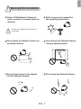
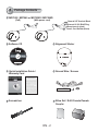
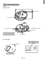
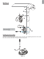
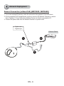
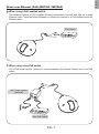
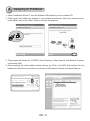
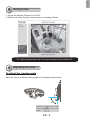
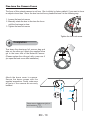
MD7530/7530D
MD7560/7560D
Vandal-proof . Mobile Surveillance
P/N:625011800G Ver1.0
Copyright c 2010 VIVOTEK INC. All rights reserved.
English
Warning Before Installation
Power off the Network Camera as
soon as smoke or unusual odors are
detected.
Refer to your user’s manual for
the operating temperature.
Contact your distributor in the event of
occurrence.
Do not place the Network Camera on
unsteady surfaces.
Do not touch the Network Camera
during a lightning storm.
Do not insert sharp or tiny objects
into the Network Camera.
Do not drop the Network Camera.
EN - 1
1
Package Contents
MD7530 / MD7560 or MD7530D / MD7560D
(PoE)
(With power cord)
General I/O Terminal Block
Ethernet 10/100 RJ45 Plug
Microphone In (pink)
Power Cord Socket (black)
Alignment Sticker
Software CD
510000210G
Quick Installation Guide /
Warranty Card
Ground Wire / Screws
Screwdriver
Silica Gel / RJ45 Female/Female
Coupler
EN - 2
English
2
Physical Description
Inner View
Screw Holes
Lens
Temperature Sensor
MicroSD/SDHC Card Slot
Status LED
The event will be triggered
once the temparature inside the
Network Camera reaches 60°C.
Reset Button
Outer View
Record the MAC address
before installing the camera.
Network Camera
Model No: MD7530
MAC:0002D107258A
V I
RoHS
This device complies with part 15 of the FCC rules. Operation is subject to the following two conditions:
(1)This device may not cause harmful interference, and
(2) this device must accept any interference received, including interference that may cause undesired operation.
Pat. 6,930,709
Waterproof Level: IP67
EN - 3
Made in Taiwan
3
Hardware Installation
First, use the supplied screwdriver to detach the dome cover from the camera base. Insert your
MicroSD/SDHC Card if necessary.
Tamper-proof Screw
Dome Cover
Rubber Stopper
Camera Base
Then, follow the steps below to install the camera to either the ceiling or the wall:
1. Attach the supplied alignment sticker to the ceiling/wall.
2. Using the 3 screw circles on the sticker, drill 3 pilot holes into the ceiling/wall. Then hammer the
plastic anchors into the holes if necessary.
3. This Network Camera can be mounted with the cable routed through the ceiling/wall or from the
side. If you want to feed the cable through the ceiling/wall, drill a cable hole A as shown in the
picture. If the cable goes through the side of the dome cover, please remove the rubber stopper
(B).
4. Through the 3 holes on the camera base, insert the screws to corresponding holes and secure
the camera base with a screwdriver.
Ceiling Mount
A
1
2
3
4
A
B
EN - 4
English
Wall Mount
1
2
B
A
3
Please secure the screws tightly to
avoid moisture.
4
Installing the Ground Wire
As shown in the following figure, please secure one side of the supplied ground wire to the screw
hole, then route the other side of the ground wire to the ground.
EN - 5
4
Network Deployment
General Connection (without PoE) (MD7530D / MD7560D)
1. If you have external DI devices, make the connection from general I/O terminal block.
2. Use the supplied RJ45 female/female coupler to connect the Network Camera to a switch.
Use a Category 5 Cross Cable when Network Camera is directly connected to PC.
3. Connect the power cable from the Network Camera to a power outlet.
+ : Digital input
- : Digital input
Ethernet Switch
POWER
2
1
3
EN - 6
COLLISION
1
2
3
4
5
LINK
RECEIVE
PARTITION
English
Power over Ethernet (PoE) (MD7530 / MD7560)
When using a PoE-enabled switch
This Network Camera is PoE-compliant, allowing transmission of power and data via a single
Ethernet cable. Follow the below illustration to connect the camera to a PoE-enabled switch via
Ethernet cable.
PoE Switch
POWER
COLLISION
1
2
3
4
5
LINK
RECEIVE
PARTITION
When using a non-PoE switch
Use a PoE power injector (optional) to connect between the Network Camera and a non-PoE
switch.
PoE Power Injector
(optional)
POWER
COLLISION
1
2
3
4
5
LINK
RECEIVE
PARTITION
Non-PoE Switch
EN - 7
5
Assigning an IP Address
1. Install “Installation Wizard 2” from the Software Utility directory on the software CD.
2. The program will conduct an analysis of your network environment. After your network is analyzed, please click on the “Next” button to continue the program.
Installation
Wizard 2
3. The program will search for VIVOTEK Video Receivers, Video Servers, and Network Cameras
on the same LAN.
4. After searching, the main installer window will pop up. Click on the MAC that matches the one
labeled on the bottom of your device to connect to the Network Camera via Internet Explorer.
Network Camera
Model No: MD7530
00-02-D1-07-25-8A
MAC:0002D107258A
V I
RoHS
This device complies with part 15 of the FCC rules. Operation is subject to the following two conditions:
(1)This device may not cause harmful interference, and
(2) this device must accept any interference received, including interference that may cause undesired operation.
Pat. 6,930,709
192.168.5.151
0002D107258A
Made in Taiwan
EN - 8
MD7530
English
6
Ready to Use
1. Access the Network Camera on the LAN.
2. Retrieve live video through a web browser or recording software.
For further setup, please refer to the user's manual on the software CD.
7
Adjusting the Lens
To adjust the viewing angle
Adjust the lens to a desired viewing angle as the diagram shown below.
90°
DO NOT over rotate the lens. Doing
so will damage the camera lens
module.
EN - 9
Fine-tune the Camera Focus
The focus of this network camera is set from 1.0m to infinity by factory default. If you want to focus
on objects closer than 1.0m or the lens has lost focus, please fine tune it in the following way.
1. Loosen the lens lock screw.
2. Manually rotate the lens to fine-tune the focus
until the live image is clear.
3. Tighten the lens lock screw.
Tighten the lens lock screw.
8
Completion
Tear down the aluminum foil vacuum bag and
take out the silica gel. Attach the supplied silica
gel to the inner side of the Network Camera.
(Please replace the silica gel with a new one if
you open the back cover after installation.)
Attach the dome cover to camera.
Secure the dome screws with the
supplied screwdriver. Finally, make sure
all parts of the camera are securely
installed.
Please secure the screws tightly to
avoid moisture.
EN - 10
MD7530/7530D
MD7560/7560D
Vandal-proof . Mobile Surveillance
P/N:625011800G Ver1.0
Copyright c 2010 VIVOTEK INC. All rights reserved.


![Cover [FD7132]-outline.ai](http://vs1.manualzilla.com/store/data/006040135_1-f75a148c91b11b3c3e29997e0c59b0c6-150x150.png)