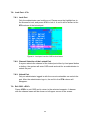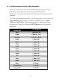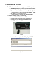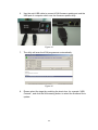
1
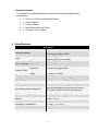
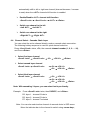
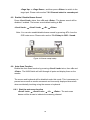
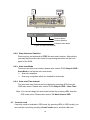
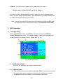
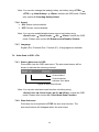
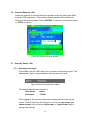
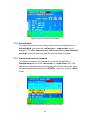
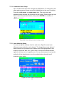
D-Link® KVM-440/KVM-450 8/16 Port Combo KVM Switch User Manual Version 1.00 Index 1. INTRODUCTION ............................................................................................................................ 4 2. SPECIFICATIONS ......................................................................................................................... 5 3. SYSTEM REQUIREMENTS ........................................................................................................... 6 4. INSTALLATION ............................................................................................................................. 6 4.1. FRONT VIEW ............................................................................................................................ 6 4.3. SINGLE STAGE INSTALLATION ................................................................................................... 7 4.3.1. Precautions: ................................................................................................................ 7 4.3.2. Console Connection: .................................................................................................. 8 4.3.3. System Connections: ................................................................................................. 9 4.4. CASCADE CHAINING............................................................................................................... 11 RACK MOUNTING ................................................................................................................................ 14 5. OPERATION ................................................................................................................................ 14 6. HOTKEY OPERATION ................................................................................................................ 15 6.1. CALL OSD MENU .................................................................................................................. 15 6.2. LEADING HOTKEY SELECT ..................................................................................................... 15 6.3. CHANNEL SELECT - SINGLE KVM ........................................................................................... 15 6.3.1. Specific Channel Selection ...................................................................................... 15 6.3.2. Arrow Key Channel Shift Function .......................................................................... 16 6.3.3. <ALT> Channel Shift Function ................................................................................. 16 6.4. CHANNEL SELECT - CASCADE CHAIN LAYER .......................................................................... 17 6.5. ENABLE / DISABLE BUZZER SOUND ........................................................................................ 18 6.6. AUTO-SCAN FUNCTION .......................................................................................................... 18 6.6.1. Start the auto-scan function .................................................................................... 18 6.6.2. Stop Auto-scan Function.......................................................................................... 19 6.6.3. Auto-scan Mode ........................................................................................................ 19 6.6.4. Auto-scan Time Interval ............................................................................................ 19 6.7. 7. CONSOLE LOCK ..................................................................................................................... 19 OSD OPERATION ....................................................................................................................... 20 7.1. OSD MAIN MENU .................................................................................................................. 20 7.1.1. KVM layer Number .................................................................................................... 20 7.1.2. Channel Name ........................................................................................................... 20 7.1.3. Computer & KVM Status .......................................................................................... 21 7.1.4. Current Active Channel Number.............................................................................. 21 7.1.5. Cascade Parent Channel Number ........................................................................... 21 2 7.1.6. Page Up / Down Indicator ......................................................................................... 21 7.1.7. Function Control Menu ............................................................................................. 22 7.2. CHANNEL SELECTION IN OSD ................................................................................................ 22 7.2.1. Channel Select to Computer .................................................................................... 22 7.2.2. Channel Select to Cascade Port .............................................................................. 22 7.2.3. Return from Cascade Port........................................................................................ 23 7.3. SETUP IN OSD: <F1> ............................................................................................................ 23 7.3.1. Scan Mode ................................................................................................................. 23 7.3.2. Scan Time ................................................................................................................... 24 7.3.3. Banner Time ............................................................................................................... 24 7.3.4. Position ...................................................................................................................... 24 7.3.5. Hotkey ........................................................................................................................ 24 7.3.6. Sound ......................................................................................................................... 25 7.3.7. Language ................................................................................................................... 25 7.4. AUTO-SCAN IN OSD: <F2>.................................................................................................... 25 7.4.1. Start to Auto-scan in OSD ........................................................................................ 25 7.4.2. Stop Auto-scan .......................................................................................................... 25 7.4.3. Auto-scan Mode ........................................................................................................ 26 7.4.4. Auto-scan Time Interval ............................................................................................ 26 7.5. CONSOLE LOCK IN OSD: <F3> .............................................................................................. 26 7.6. CHANNEL RENAME: <F4> ...................................................................................................... 27 7.7. SECURITY SETUP: <F5> ........................................................................................................ 27 7.7.1. Security mode login .................................................................................................. 27 7.7.2. Security Mode............................................................................................................ 28 7.7.3. Change Administrator Password............................................................................. 28 7.7.4. Authorized User Setup ............................................................................................. 29 7.7.5. User Authority Setup ................................................................................................ 29 7.8. LOCK PORT: <F6>................................................................................................................. 30 7.8.1. Lock Port .................................................................................................................... 30 7.8.2. Channel Selection of the Locked Port .................................................................... 30 7.8.3. Unlock Port ................................................................................................................ 30 7.9. EXIT OSD: <ESC> ................................................................................................................ 30 8. SUN MICROSYSTEMS FUNCTION KEY EMULATION: ............................................................ 31 9. TROUBLESHOOTING : ............................................................................................................... 32 10. FIRMWARE UPGRADE PROCEDURES .................................................................................... 33 3 1. Introduction Thank you for purchasing a D-Link Combo KVM Switch. You now have a durable, high quality system to control multiple PCs via a single console. z Features 1. Connect your console keyboard/mouse via PS/2 2. Connect computers via PS/2 and/or USB 3. Support for Windows, Linux, Mac OS9/OSX, and Sun Microsystems Operating Systems 4. On-Screen-Display (OSD) & Cascade Chain functions 5. Intuitive on-screen menus for quick and efficient navigation 6. Supports daisy chaining with up to 3 cascade levels. Cascaded units do not require a special configuration. 7. Emulates a PS/2 or USB keyboard on each PC allowing them to boot normally without a keyboard error. 8. Supports hot-plugging: All devices connected to the KVM can be added or removed at any time without shutting down the KVM. 9. Select a PC to switch to using one of 3 interfaces: - Front Panel Button - Hot-Keys on a PS/2 keyboard - OSD Menu (On Screen Display) 10. Supports Auto-Scan function to switch video inputs automatically among computers sequentially at preset intervals via OSD menu 11. Supports LED display for PC and/or server status monitoring 12. Supports monitor resolutions up to 2048 x 1536 13. Supports “beeper” when switching is enabled 14. Fully compliant with USB 1.1/ 2.0 specifications 15. Rack mountable in 19” system rack (1U) 4 Package Contents The product you purchased should contain the following equipment and accessories: 1 x 8-Port or 16-Port Combo KVM Switch 1 x User’s Manual 1 1 4 x Power Adaptor x Rack Mount Bracket Kit Set x Customer 4-in-1 cables 2. Specifications Specification Number of Computers Controlled 8 or 16 Selection Method Push Button and Hot-Key (PS/2 Keyboard) or On-Screen-Display (OSD) LEDs Red for PC Selection Green for PC On-Line ready PC Connectors Console Ports Video 8 / 16 x HDB-15 female (KB/MS) (PS/2 & USB signal combined) Keyboard 1 x 6 pin mini-DIN female Mouse 1 x 6 pin mini-DIN female Video 1 x HDB-15 female Firmware Upgrade Port Mini USB Auto-Scan Interval Adjustable time setting by OSD menu DDC, DDC2 monitor Max. Resolution up to 2048 x1536@65Hz Hot Swappable Yes Operating systems supported Windows 98SE/ME/2000/XP/2003/Vista Server, Linux, Mac OS9/OSX and Sun Microsystems. Power By external power adaptor Dimensions (L X W X H) 44 x 15.7 x 4.5 cm (17.3 x 6.1 x 1.5 inch) Weight 1750g / 1900 g Housing material Metal Operating Temperature 32~122°F Humidity 0%~80% Relative Humidity 5 (0~50°C) Sel ect ed( Red) : Ther edLEDi ndi c at est hatt hec or r es pondi ngPCi ss el ec t ed. OnLi ne( Gr een) : Thegr eenLEDi ndi c at est hatt hec or r es pondi ngPCi sonl i ne. 7 4.3.2. Console Connection: Plug the keyboard, mouse, and monitor into the console ports on the rear panel of the KVM Switch. (Figure 5) Figure 5: Console connection 8 4.3.3. System Connections: Use the custom combo cable to connect your computers. Refer to the figures and instruction shown below for information about connecting the KVM to PCs. Note: Please contact your reseller to purchase the custom combo 4-in-1 cables if needed. Figure 6: Custom combo 4-in-1 cable 9 You can connect the KVM switch to computers using one of the three methods shown below: A. Connect USB, PS/2 (keyboard/mouse) and VGA connectors to computers. We recommend that users connect computers in the manner shown below. (Figure 7) Figure 7: USB & PS/2 (Keyboard & Mouse) and VGA connected B. Connect only PS/2 (keyboard/mouse) and VGA connectors to computers (Figure 8). Figure 8: PS/2 (Keyboard & Mouse) and VGA connected 10 C. Connect only USB and VGA connectors to computers. (Figure 9). Figure 9: USB and VGA video connected 4.4. Cascade Chaining The KVM switch supports cascades of up to 3 levels. Control up to 64/256/4096 PCs from a single console. Cascaded units do not require any special configuration. A cascade configuration expands the system’s capabilities and allows you to select computers connected to the Master or Slave. Once connected, the KVM Switches will automatically configure themselves appropriately as the Master or Slave. To install a cascade chain, please follow the instruction below. A. Power off any attached computers/devices before installing the KVM Switch. B. Use the custom combo cable set (See Figure 6) to connect one or more Slave KVM Switches to any PC port of Master KVM Switch. The KVM to KVM must be connected through a PS/2 connection. (Please refer to Figure 7 & Figure 8). C. Plug in the power adapter of the first level Master KVM Switch and connect Master KVM switch to computers. 11 D. Plug in the power adapter for each level Slave KVM Switch and connect Slave KVM switch to computers. E. The power on sequence should be: 1. Master KVM Switch 2. Second level Slave KVM Switch (connect to Master KVM Switch) if needed. 3. Third level Slave KVM Switch (connect to second level Slave KVM Switch) if needed. 4. All computers connected to the Master/Slave KVM Switch. F. After all KVM Switches are powered by power adaptors, turn on the computers. z Initial Plug-in Process: Please plug in the Master KVM Switch first before turning on any other devices such as monitors or computers. z Hot plugging and hot swapping: The KVM switch supports hot plugging and hot swapping. 12 Figure 10: Cascade chaining 13 6. Hotkey Operation 6.1. Call OSD Menu Press <Scroll Lock> twice and <Enter>, then the OSD “Main Menu” will be displayed on the monitor screen. All of the KVM parameters can be setup in OSD mode. You can also execute some KVM functions in OSD. <Scroll Lock> → <Scroll Lock> → <Enter> 6.2. Leading Hotkey Select The two-step hotkey sequence is used for quick function execution. The leading key is <Scroll Lock> by default. However, you may change the leading hotkey if you want. By pressing <CTRL> twice, <New Hotkey>, then pressing <Enter>, you can change the leading hotkey. The available leading hotkey are <Scroll Lock>, <Num Lock> or <Caps Lock> for option. ¾ Set leading hotkey to <Scroll Lock> <CTRL> → <CTRL> → <Scroll Lock> → <Enter> ¾ Set leading hotkey to <Num Lock> <CTRL> → <CTRL> → <Num Lock> → <Enter> ¾ Set leading hotkey to <Caps Lock> <CTRL> → <CTRL> → <Caps Lock> → <Enter> Note: You can also change leading hotkey by pressing <F1> from the OSD main menu. Please refer section 7.3.5 Setup in OSD – Hotkey. 6.3. Channel Select - Single KVM 6.3.1. Specific Channel Selection You can select the connected computers using the two-step Hotkey sequence. Press <Scroll Lock> key twice (Step 1), then press key (1 to 16) and <Enter> (step 2) to select the computer you want to control. 15 Figure 12: Specific channel selection hotkey or or … … <Scroll Lock> → <Scroll Lock> → <1> → <Enter> <Scroll Lock> → <Scroll Lock> → <2> → <Enter> <Scroll Lock> → <Scroll Lock> → <16> → <Enter> Note: You can also select computers using the OSD menu. Move the indicator bar to the channel to switch using <arrow key>, <Page Up> or <Page Down>, then press <Enter> to select the connected computer. Please refer section 7.2 Channel Selection in OSD. 6.3.2. Arrow Key Channel Shift Function Press <Scroll Lock> twice, and press the <Left Arrow> or <Right Arrow> key to shift left/right one channel. ¾ Switch one channel to the left <Scroll Lock> → <Scroll Lock> → <Left Arrow> ¾ Switch one channel to the right <Scroll Lock> → <Scroll Lock> → <Right Arrow> 6.3.3. <ALT> Channel Shift Function 1. Start <ALT> Channel shift Function <ALT> channel shift function is off by default. You can press the Hot-Key <Scroll Lock> twice, <ALT> and then press <Enter> to turn this function on or off. 2. Switch channels using the <ALT> key Press either the left or right <ALT> key twice, the PC channel will 16 automatically shift to left or right one channel (channel decrease / increase to next) when the <ALT> channel shift function is enabled. ¾ Enable/Disable <ALT> channel shift function <Scroll Lock> → <Scroll Lock> → <ALT> → <Enter> ¾ Switch one channel to the left <Left ALT> → <Left ALT> ¾ Switch one channel to the right <Right ALT> → <Right ALT> 6.4. Channel Select - Cascade Chain Layer You can select the active channel directly under a cascade chain connection. The following hotkey sequence is used for quick channel selection. Press <Scroll Lock> twice, <D>, the cascade channel number (1, 2, 3……16), and Press <Enter>. ¾ Select first layer channel <Scroll Lock> → <Scroll Lock> → <D> → <CH-L1> → <Enter> ¾ Select second layer channel <Scroll Lock> → <Scroll Lock> ¾ Select third layer channel <Scroll Lock> → <Scroll Lock> → <D> → <CH-L1> → <D> → <CH-L2> → <Enter> → <D> → <CH-L1> → <D> → <CH-L2> → <D> → <CH-L3> → <Enter> Note: With cascading 3 layers, you can select last layer directly. Example: Press <Scroll Lock> twice, then D2D5D7, and <Enter>: D2: layer 1 - channel 2 links to D5: layer 2 - channel 5 links to D7: layer 3 - channel 7 selected Note: You can also select active channel of cascade chain in OSD menu. Move the indicator bar to the channel to switch using <arrow key>, 17 <Page Up> or <Page Down>, and then press <Enter> to switch to the target port. Please refer section 7.2.2 Channel select to cascade port. 6.5. Enable / Disable Buzzer Sound Press <Scroll Lock> twice, then <B> and <Enter>. The buzzer sound will be disabled / enabled. The buzzer sound default setting is ON. <Scroll Lock> → <Scroll Lock> → <B> → <Enter> Note: You can also enable/disable buzzer sound by pressing <F1> from the OSD main menu. Please refer section 7.3.6 Setup in OSD - Sound. . Figure 13: Buzzer setup hotkey 6.6. Auto-Scan Function Enable the Auto-Scan function by pressing <Scroll Lock> twice, then <S> and <Enter>. The KVM Switch will shift through all ports and display them on the monitor. The mouse and keyboard will be disabled under this mode. This is necessary to prevent errors such as erratic movement and incorrectly displayed characters when accidentally touching using the mouse or keyboard. 6.6.1. Start the auto-scan function <Scroll Lock> → <Scroll Lock> → <S> → <Enter>. The auto-scan banner will be shown to indicate the scanning channel. 18 Figure 14: Auto-scan hotkey Channel Name Channel Number Indicates Scan Mode Figure 15: Auto-scan Banner 6.6.2. Stop Auto-scan Function Press any key on keyboard to STOP the auto-scan function. Alternatively you may stop the auto-scan function by pressing the button on the front panel of the KVM. 6.6.3. Auto-scan Mode There are two auto-scan modes, please refer section 7.3.1 Setup in OSD – Scan Mode to set up the auto-scan mode. ¾ Scan all computers. ¾ Scan any computers which are marked for auto-scan. 6.6.4. Auto-scan Time Interval The auto-scan time interval can be adjusted by pressing <F1> from the OSD main menu. Please refer section 7.3.1 Setup in OSD – Scan Time. Note: You can also begin the auto-scan function by pressing <F2> from the OSD main menu. Please refer section 7.4 Auto-Scan in OSD. 6.7. Console Lock If security mode is enabled in OSD mode (by pressing <F5> in OSD mode), you can lock the console by pressing <Scroll Lock> twice, and then <H> and 19 <Enter>. The KVM will be locked until an authorized user logs in. <Scroll Lock> → <Scroll Lock> → <H> → <Enter> To unlock console, please press any key according to screen message, then key in the User Name and Password. The KVM switch and console devices will be unlocked and returned to normal status. Note: You can also execute the console lock function by pressing <F3> from the OSD main menu. Please refer section 7.5 Console Lock in OSD. 7. OSD Operation 7.1. OSD Main Menu Press <Scroll Lock> twice and <Enter>, then you will enter to OSD (On Screen Display) main menu. The channel number, names and the status will be displayed on the monitor screen. Please refer fig. 16 Fig. 16: OSD main menu 7.1.1. KVM layer Number 1st, 2nd or 3rd. indicates thescurrent cascade level. s 7.1.2. Channel Name ¾ The channel name can be defined using the F4 key. Channel names help to remind users which computer is connected to a particular channel. ¾ A highlighted pink bar is shown in the selected channel row. 20 ¾ A plus mark (+) showing in the left of channel name indicates that the port that is cascaded. 7.1.3. Computer & KVM Status ¾ KVM buzzer status Buzzer sound on Buzzer sound off ¾ Logged-in User Name The system has one administrator and 3 user accounts for security management. The name of the currently logged-in user is displayed here. ¾ Channel LOCK Indicator (Status STA) L: Indicates that this channel is locked. BLANK: Indicates that this channel is not locked. ¾ Computer power on indicator (Status STA), OSD menu will update the flag automatically if the computer status changes. A: Indicates that this computer is powered on and selectable. BLANK: Indicates that this computer is not connected or powered on. ¾ Channel scan indicator (Status STA) S: This channel is marked for auto-scan if the scan mode is Select type. BLANK: Indicates that this computer is not marked for auto-scan. 7.1.4. Current Active Channel Number This indicates the current active channel number. The channel of the currently selected computer is displayed in the upper-right corner. If the active channel is in 2nd or 3rd cascade layer, the display string will be displayed in the format XX-YY-ZZ. For example, 02-05-07 means the active channel is layer 1 - channel 2 links to layer 2 - channel 5, and layer 3 - channel 7 is selected as the active channel. 7.1.5. Cascade Parent Channel Number This indicates the parent channel of the cascade layer. The number at the upper-left corner below KVM layer number shows the port number for the upper layer (i.e. 8 indicates a link from channel 8 of the upper KVM switch). It is valid only for the 2nd and 3rd cascade layer. The OSD will display a blank for the 1st layer since there is no parent channel. 7.1.6. Page Up / Down Indicator Note: When using a 16-port KVM Switch, the information about ports 1 ~ 8 is displayed on the first page, and information for ports 9 ~ 16 is displayed 21 on the second page. Since the port information is divided onto two pages, the page down / up indicator is a reminder to switch to alternative pages using the <page down> or <page up> key. 7.1.7. Function Control Menu The detail of control functions will be described in later sections. The list of control functions: F1: Set Up: Basic set up menu F2: Scan: Autoscan function F3: Lock: Setup lock/unlock, only available when F5 Security is enabled F4: Rename: Rename selected channel name F5: Security: Security function and user authority settings F6: Lock Port: PC port lock function (for administrator only) 7.2. Channel Selection in OSD 7.2.1. Channel Select to Computer Use the <UP> and <DOWN> arrow keys to highlight a computer and then <ENTER> to select it and leave OSD menu. A banner with the channel name will be shown on left-upper corner of the screen. Channel Name Channel Number Fig. 17: Channel Banner (Single Layer) 7.2.2. Channel Select to Cascade Port A plus mark (+) showing to the left of the channel name indicates that the port is under the cascade channel. Pressing <ENTER> in this channel will enter one level down, and the screen will display a list of the computers connected to the slave KVM. 22 Channel Name Channel Number 2nd Layer Channel Number 1st Layer Channel Number Fig. 18: Channel Banner (Cascade Layer) 7.2.3. Return from Cascade Port After entering cascade port, pressing <R> will return to the upper layer OSD menu. 7.3. Setup in OSD: <F1> Please use the <Up> or <Down> arrow keys to select the item you want to change, and use <Left> or <Right> arrow keys to change the settings. Press <ESC> to exit and save your configuration. Figure 19: OSD Setup 7.3.1. Scan Mode ¾ Select: Scan the selected channels marked with S in the STA column on the OSD main menu. ¾ PC ON: Scan all PC channels which are powered on. 23 7.3.2. Scan Time The default scan time is 5 seconds. Scan time can be increased to up to 90 seconds at 5 second increments. 7.3.3. Banner Time The default banner time is 5 seconds. It can be changed to 10 seconds, 15 seconds, or always on (∞). 7.3.4. Position ¾ Menu: Use four arrow keys to move the OSD main menu to the desired position. Press <ESC> to save the adjusted menu position. Figure 20: Menu Position Setup ¾ Banner: Use four arrow keys to move the channel banner to the desired position. Press <ESC> to save the adjusted banner position. Figure 21: Banner Position Setup 7.3.5. ¾ ¾ ¾ Hotkey Scroll Lock: <Scroll Lock> becomes the hotkey. Num Lock: <Num Lock> becomes the hotkey. Cap Lock: <Cap Lock> becomes the hotkey. 24 Note: You can also change the leading hotkey via hotkey using <CTRL> → <CTRL> → <New Hotkey> → <Enter> outside the OSD mode. Please refer section 6.2 Leading Hotkey Select. 7.3.6. Sound ¾ ON: Buzzer sound enabled. ¾ OFF: Buzzer sound disabled. Note: You can also enable/disable buzzer sound via hotkey using <Scroll Lock> → <Scroll Lock> → <B> → <Enter> outside the OSD mode. Please refer section 6.5 Buzzer sound Disable / Enable. 7.3.7. Language English (En) / Deutsch (De) / Francais (Fr), 3 languages are available. 7.4. Auto-Scan in OSD: <F2> 7.4.1. Start to Auto-scan in OSD Press <F2> from the OSD main menu. The auto-scan banner will be shown to indicate the scanning channel. Channel Name Channel Number Indicates Scan Mode Figure 22: Auto-Scan Banner Note: You can also start auto-scan function via hotkey using <Scroll Lock> → <Scroll Lock> → <S> → <Enter> outside the OSD mode. Please refer section 6.6.1 Start Auto-Scan Function. 7.4.2. Stop Auto-scan Press any key on keyboard to STOP the auto-scan function. The auto-scan banner will disappear when the scan stops. 25 7.4.3. Auto-scan Mode There are two auto-scan modes, please refer section 7.3.1 Setup in OSD – Scan Mode to set up the auto-scan mode. ¾ Scan all computers which are power on. ¾ Scan all computers which are marked for auto-scan. 7.4.4. Auto-scan Time Interval The auto-scan time interval of each port displayed can be adjusted by pressing <F1> from the OSD main menu. Please refer section 7.3.2 Setup in OSD – Scan Time. 7.5. Console Lock in OSD: <F3> If the security mode is enabled in OSD mode (by pressing <F5> in OSD mode, please refer section 7.7 Security Setup in OSD). You can logout to lock the console by pressing <F3> In OSD mode. The Console Lock Banner will be shown on the screen. Figure 23: Console Lock Banner The KVM will be locked until an authorized user logs in. Figure 24: Unlock window Note: When outside of OSD mode you can also log out to lock the console via hotkey using <Scroll Lock> → <Scroll Lock> → <H> → <Enter>. Please refer section 6.7 Console Lock. Note: If you forget the password, the only way to permanently disable the security function is to key in a universal password to unlock the KVM. You need to key in this unlock password to unlock the KVM, and then you can reinitialize the system. Please contact your agency/distributor to obtain the universal password. 26 7.6. Channel Rename: <F4> Select the channel to rename using the up/down arrow key and press <F4> from the OSD main menu. The channel rename window will be shown for setting up the channel name. Press <ENTER> to save the new channel name or <ESC> to cancel. Figure 25: Channel Rename window 7.7. Security Setup: <F5> 7.7.1. Security mode login Press <F5> from the OSD main menu to enter security setup mode. The administrator login is required before entering security mode. Figure 26: Security mode login window The default administrator account is: User Name: Password: admin 123456 After logging in, the security setup main window will be shown on the screen. Please select the security item to set up via <up arrow> and <down arrow> key, and press <left arrow> or <right arrow> key to change the settings. 27 Figure 27: Security setup main window 7.7.2. Security Mode To change the security mode setting, please move the highlight bar to Security Mode, and press the <left arrow> or <right arrow> key to change it. The <F3> Console Lock, <F6> Port Lock and user authority functions cannot be executed until the security mode is enabled. 7.7.3. Change Administrator Password To change the administrator password, move the highlight bar to Admin/password, and press <left arrow> or <right arrow> key. The administrator password setup window will be shown on the screen. Input the new password twice and press <ENTER> to confirm, or press <ESC> to exit. Figure 28: Administrator password setup window 28 7.7.4. Authorized User Setup Up to 3 authorized users can manage the KVM switch. To change the user name and password, please move the highlight bar to the user for editing. Press the <left arrow> or <right arrow> key. The user name and password setup window will be shown on the screen. Please Input the new user’s name and password twice, then press <ENTER> to confirm or <ESC> to cancel. Figure 29: User name password setup window 7.7.5. User Authority Setup You can set up the authority level for each user. Specific users have different access rights for each channel. To change the access rights of each channel for a particular user, please move the highlight bar to the channel, and press <A>, <1>, <2> or <3> to set up the channel access rights for all users or for a specific user. You are not required to set up the authority of the administrator since the administrator already has all channel access rights. Figure 30: User authority setup window 29 7.8. Lock Port: <F6> 7.8.1. Lock Port Only the administrator can lock the port. Please move the highlight bar to the channel to lock, and press <F6> to lock it. A red L will be shown in the STA column of the locked port. Figure 31: Lock port from the OSD main window 7.8.2. Channel Selection of the Locked Port If anyone selects the channel of the locked port either by front panel button or hotkey, the system will enter OSD mode and wait for an administrator to unlock the port. 7.8.3. Unlock Port Only an administrator logged in with the correct credentials can unlock the port. After the administrator logs in, the red L in the STA column will disappear. 7.9. Exit OSD: <ESC> Press <ESC> to exit OSD and to return to the selected computer. A banner with the channel name will be shown on left-upper corner of the screen. 30 8. Sun Microsystems Function Key Emulation: There are 16 special functions on the Sun Microsystems keyboard, Combo KVM Switch can emulate these function keys via PS/2 keyboard. Please refer to the table shown below for Sun Microsystems keyboard special functions. To activate SUN keyboard emulation on the PS/2 keyboard, you must press the <LEFT Window> key first (this key usually is located between the <LEFT CTRL> and <LEFT ALT>). Then press the second key (Sun Microsystems Function Key). Please do not release <LEFT Window> when you press the second key. Sun Microsystems Function Key PS/2 Keyboard Stop L_Win & L_Alt Props L_Win & L_Ctrl Compose L_Win & L_Shift Front L_Win & F1 Open L_Win & F2 Find L_Win & F3 Again L_Win & F4 Undo L_Win & F5 Copy L_Win & F6 Paste L_Win & F7 Cut L_Win & F8 Help L_Win & F11 Power L_Win & F12 Mute L_Win & 1 Volume Down L_Win & 2 Volume UP L_Win & 3 31 9. Troubleshooting : Symptom Possible Cause Recommended Solution Keyboard and/or Mouse not working Keyboard and/or Mouse need to be reset. Unplug the cables from the console port(s), and then plug them back in. Check the cable from the switch to the computer and make sure it is connected properly. Power off all connected devices and then power them up again. Make sure the console of the Slave is connected to the Master’s PC port. Remove any power supplies to the slave (unplug all cables) before connecting it to the Master. Remove any power supplies to the Slave (unplug all cables), before connecting it to the Master. Make sure the cable is connected correctly: Slave console link to Master port. Use <F1>: Set/Position to move OSD menu and banner to the proper position. Failed connection to the computer. KVM Switch needs to be reset. Master/ Slave chaining does not work Incorrect configuration or improper installation procedures. Double OSD images displayed with a cascade configuration Improper slave connection procedure. Failed connection. OSD menu is not displayed in the correct position The OSD menu has fixed resolution and its size varies due to the changes of computer VGA resolution. 32 10.Firmware Upgrade Procedures The KVM switch provides the firmware upgrade for the following functions: USB console: Update for USB console keyboard/mouse compatibility. The firmware filename for USB console is like Dlink_KVM_Vxxx_bx.USB. PS/2 console: Update for PS/2 console keyboard/mouse compatibility. The firmware filename for PS/2 console is like Dlink_KVM_Vxxx_bx.PS2. OSD: Update for on-screen-display functions. The firmware filename for OSD is like Dlink_KVM_Vxxx_bx.OSD. To update the firmware, please do the followings: 1. Disconnect all the KVM cable between KVM and computer. 2. Disconnect all the keyboard and mouse plugged on KVM. 3. Disconnect the VGA cable between KVM and monitor. 4. Apply DC 5V adapter to the KVM. Figure 32 5. Execute the firmware update utility “KVM_utility_V100.EXE”. Figure 33 33 6. Use the mini-USB cable to connect KVM firmware update port and the USB port of computer which runs the firmware update utility. Figure 34 7. The utility will scan the KVM programmer automatically. Figure 35 8. Please select the target by enabling the check box, for example “USB Console”, and click the file browsing button to select the firmware file to update. 34 Figure 36 9. Select the firmware file to update. Figure 37 10. Click the “Program” button to start firmware programming. Figure 38 35 11. A status bar is shown under the panel to indicate the update progress. Figure 39 12. The firmware is updated successfully. Figure 40 13. Unplug the power adapter for a moment, and plug it back in to restart the device. 36 Disclaimer Information in this document is subject to change without notice. The manufacturer does not make any representations or warranties (implied or otherwise) regarding the accuracy and completeness of this document and shall in no event be liable for any loss of profit or any other commercial damage, including but not limited to special, incidental, consequential, or other damages. No part of this document may be reproduced or transmitted in any form by any means, electronic or mechanical, including photocopying, recording or information recording and retrieval systems without the express written permission of the manufacturer. All brand names and product names used in this document are trademarks, or registered trademarks of their respective holders. Federal Communication Commission Interference Statement This equipment has been tested and found to comply with the limits for a Class B digital device, pursuant to Part 15 of the FCC Rules. These limits are designed to provide reasonable protection against harmful interference in a residential installation. This equipment generates, uses, and can radiate radio frequency energy and, if not installed and used in accordance with the instructions, may cause harmful interference to radio communications. not occur in a particular installation. However, there is no guarantee that interference will If this equipment does cause harmful interference to radio or television reception, which can be determined by turning the equipment off and on, the user is encouraged to try to correct the interference by one of the following measures: • Reorient or relocate the receiving antenna. • Increase the separation between the equipment and receiver. • Connect the equipment into an outlet on a circuit different from that to which the receiver is connected. • Consult the dealer or an experienced radio/TV technician for help. FCC Caution: Any changes or modifications not expressly approved by the party responsible for compliance could void the user's authority to operate this equipment. This device complies with Part 15 of the FCC Rules. Operation is subject to the following two conditions: (1) This device may not cause harmful interference, and (2) this device must accept any interference received, including interference that may cause undesired operation. This equipment has been tested and found to comply with the limits for a Class B digital device, pursuant to Part 15 of the FCC Rules. These limits are designed to provide reasonable protection against harmful interference in a residential installation. Industry Canada Statement This Class B digital apparatus complies with Canadian ICES-003. Operation is subject to the following two conditions: (1) this device may not cause interference, and (2) this device must accept any interference, including interference that may cause undesired operation of the device. Cet appareil numérique de la classe B conforme á la norme NMB-003 du Canada. 37