1
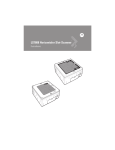
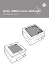
Symbol LS7808
Horizontal Slot Scanner
Product Reference Guide
Symbol LS7808 Horizontal Slot Scanner
Product Reference Guide
72E-73952-03
Revision A
September 2007
ii
Symbol LS7808 Horizontal Slot Scanner Product Reference Guide
© 2007 by Motorola, Inc. All rights reserved.
No part of this publication may be reproduced or used in any form, or by any electrical or mechanical means,
without permission in writing from Motorola. This includes electronic or mechanical means, such as
photocopying, recording, or information storage and retrieval systems. The material in this manual is subject to
change without notice.
The software is provided strictly on an “as is” basis. All software, including firmware, furnished to the user is on
a licensed basis. Motorola grants to the user a non-transferable and non-exclusive license to use each
software or firmware program delivered hereunder (licensed program). Except as noted below, such license
may not be assigned, sublicensed, or otherwise transferred by the user without prior written consent of
Motorola. No right to copy a licensed program in whole or in part is granted, except as permitted under
copyright law. The user shall not modify, merge, or incorporate any form or portion of a licensed program with
other program material, create a derivative work from a licensed program, or use a licensed program in a
network without written permission from Motorola. The user agrees to maintain Motorola’s copyright notice on
the licensed programs delivered hereunder, and to include the same on any authorized copies it makes, in
whole or in part. The user agrees not to decompile, disassemble, decode, or reverse engineer any licensed
program delivered to the user or any portion thereof.
Motorola reserves the right to make changes to any software or product to improve reliability, function, or
design.
Motorola does not assume any product liability arising out of, or in connection with, the application or use of
any product, circuit, or application described herein.
No license is granted, either expressly or by implication, estoppel, or otherwise under any Motorola, Inc.,
intellectual property rights. An implied license only exists for equipment, circuits, and subsystems contained in
Motorola products.
MOTOROLA and the Stylized M Logo and Symbol and the Symbol logo are registered in the US Patent &
Trademark Office. Bluetooth is a registered trademark of Bluetooth SIG. Microsoft, Windows and ActiveSync
are either registered trademarks or trademarks of Microsoft Corporation. All other product or service names
are the property of their respective owners.
Motorola, Inc.
One Motorola Plaza
Holtsville, New York 11742-1300
http://www.symbol.com
iii
Revision History
Changes to the original manual are listed below:
Change
Date
Description
-01 Rev. A
9/2006
Initial release.
-02 Rev. A
2/2007
Update service information, add parameter bar codes for Bookland ISBN, new UPC
supplemental decode options, report software version, report MIMIC version, report
Synapse cable; update LS7808-SR20007TCR installation instructions.
-03 Rev. A
9/2007
Remove information for the LS7808-SR20008SNR, and add information for the
LS7808-SR2X009SCR slot scanners; remove RS-232 No Host programming bar
code.
iv
Symbol LS7808 Horizontal Slot Scanner Product Reference Guide
Table of Contents
About This Guide
Introduction ....................................................................................................................
Chapter Descriptions .....................................................................................................
Notational Conventions..................................................................................................
Related Publications ......................................................................................................
Service Information........................................................................................................
xiii
xiii
xiv
xv
xv
Chapter 1: Getting Started
Introduction ...................................................................................................................
Configurations ...............................................................................................................
Interfaces ......................................................................................................................
Unpacking the Scanner ................................................................................................
Accessories ..................................................................................................................
Views/Parts ...................................................................................................................
Input/Output Ports .........................................................................................................
Setting Up the Scanner .................................................................................................
Power Options ........................................................................................................
Connecting the Host and Peripheral Cables ...........................................................
Routing Cables .............................................................................................................
Removing Cables .........................................................................................................
Configuring the Scanner ...............................................................................................
Synchronization of Settings ....................................................................................
Beeper Tone and Volume .......................................................................................
Installation .....................................................................................................................
Typical Layouts .......................................................................................................
Installing the Symbol LS7808 .................................................................................
Electronic Article Surveillance (EAS) ............................................................................
Checkpoint® EAS Model Compatibility ...................................................................
Deactivation for Sensormatic EAS System .............................................................
Connecting the EAS Antenna .................................................................................
Connecting the EAS Interlock .................................................................................
LS7808 Interlock Cable and EAS ...........................................................................
Connecting Host Interfaces ..........................................................................................
1-1
1-2
1-2
1-3
1-3
1-4
1-5
1-6
1-6
1-6
1-7
1-8
1-9
1-9
1-9
1-10
1-10
1-12
1-14
1-14
1-15
1-15
1-15
1-16
1-16
vi
Symbol LS7808 Horizontal Slot Scanner Product Reference Guide
Chapter 2: Scanning
Introduction ...................................................................................................................
Active Scan Area ..........................................................................................................
Scanning Bar Codes .....................................................................................................
Beeper ..........................................................................................................................
Beeper Definitions ...................................................................................................
Low Power Mode ..........................................................................................................
LED Definitions .............................................................................................................
Decode Distances .........................................................................................................
2-1
2-1
2-2
2-3
2-3
2-4
2-5
2-5
Chapter 3: Maintenance, Troubleshooting & Technical Specifications
Introduction ...................................................................................................................
Maintenance .................................................................................................................
Replacing the Scan Window .........................................................................................
Replacing the Scanner Body ........................................................................................
Troubleshooting ............................................................................................................
Technical Specifications ...............................................................................................
Scanner Signal Descriptions .........................................................................................
3-1
3-1
3-2
3-3
3-4
3-6
3-8
Chapter 4: User Preferences & Miscellaneous Options
Introduction ...................................................................................................................
Scanning Sequence Examples .....................................................................................
Errors While Scanning ..................................................................................................
User Preferences Default Parameters ..........................................................................
User Preferences ..........................................................................................................
Set Default Parameter ............................................................................................
Beeper Tone ...........................................................................................................
Beeper Volume .......................................................................................................
Beep After Good Decode ........................................................................................
Timeout Between Decodes .....................................................................................
Time Delay to Low Power Mode .............................................................................
Linear UPC/EAN Decode ........................................................................................
UPC Half Block Stitching ........................................................................................
EAS Interlock ..........................................................................................................
Miscellaneous Scanner Parameters .............................................................................
Transmit Code ID Character ...................................................................................
Prefix/Suffix Values .................................................................................................
FN1 Substitution Values .........................................................................................
Scan Data Options ..................................................................................................
Report Version ..............................................................................................................
Report MIMIC Version ..................................................................................................
Report Synapse Cable ..................................................................................................
4-1
4-1
4-2
4-2
4-3
4-3
4-3
4-5
4-7
4-8
4-9
4-11
4-12
4-13
4-14
4-14
4-15
4-16
4-17
4-21
4-21
4-22
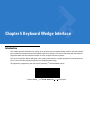
Chapter 5: Keyboard Wedge Interface
Introduction ................................................................................................................... 5-1
Connecting a Keyboard Wedge Interface ..................................................................... 5-2
Keyboard Wedge Default Parameters .......................................................................... 5-4
Table of Contents
Keyboard Wedge Host Types .................................................................................
Keyboard Wedge Country Types (Country Codes) ................................................
Ignore Unknown Characters ...................................................................................
Keystroke Delay ......................................................................................................
Intra-Keystroke Delay .............................................................................................
Alternate Numeric Keypad Emulation .....................................................................
Caps Lock On .........................................................................................................
Caps Lock Override ................................................................................................
Convert Wedge Data ..............................................................................................
Function Key Mapping ............................................................................................
FN1 Substitution .....................................................................................................
Send Make Break ...................................................................................................
Keyboard Maps .......................................................................................................
ASCII Character Set .....................................................................................................
5-5
5-7
5-13
5-14
5-16
5-17
5-18
5-19
5-20
5-22
5-23
5-24
5-25
5-27
Chapter 6: RS-232 Interface
Introduction ...................................................................................................................
Connecting an RS-232 Interface ..................................................................................
RS-232 Default Parameters ..........................................................................................
RS-232 Host Parameters ..............................................................................................
RS-232 Host Types .................................................................................................
Baud Rate ...............................................................................................................
Parity .......................................................................................................................
Check Receive Errors .............................................................................................
Hardware Handshaking ..........................................................................................
Software Handshaking ............................................................................................
Host Serial Response Time-out ..............................................................................
RTS Line State ........................................................................................................
Stop Bit Select ........................................................................................................
Data Bits .................................................................................................................
Beep on <BEL> .......................................................................................................
Intercharacter Delay ................................................................................................
Nixdorf Beep/LED Options ......................................................................................
Ignore Unknown Characters ...................................................................................
6-1
6-2
6-4
6-5
6-7
6-12
6-16
6-19
6-20
6-23
6-27
6-30
6-31
6-32
6-33
6-34
6-36
6-38
Chapter 7: USB Interface
Introduction ...................................................................................................................
Connecting a USB Interface .........................................................................................
USB Default Parameters ..............................................................................................
USB Host Parameters ..................................................................................................
USB Device Type ....................................................................................................
USB Country Keyboard Types (Country Codes) ....................................................
USB Keystroke Delay .............................................................................................
USB CAPS Lock Override ......................................................................................
USB Ignore Unknown Characters ...........................................................................
Emulate Keypad ......................................................................................................
USB Keyboard FN1 Substitution .............................................................................
Function Key Mapping ............................................................................................
7-1
7-2
7-4
7-5
7-5
7-7
7-12
7-14
7-15
7-16
7-17
7-18
vii
viii
Symbol LS7808 Horizontal Slot Scanner Product Reference Guide
Simulated Caps Lock .............................................................................................. 7-19
Convert Case .......................................................................................................... 7-20
ASCII Character Set for USB ........................................................................................ 7-22
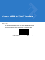
Chapter 8: IBM 468X/469X Interface
Introduction ...................................................................................................................
Connecting to an IBM 468X/469X Host ........................................................................
IBM Default Parameters ...............................................................................................
IBM 468X/469X Host Parameters .................................................................................
Port Address ...........................................................................................................
Convert Unknown to Code 39 .................................................................................
8-1
8-2
8-3
8-4
8-4
8-6
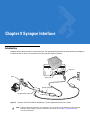
Chapter 9: Synapse Interface
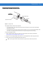
Introduction ...................................................................................................................
Connecting a Synapse Interface Cable ........................................................................
Synapse Interface ...................................................................................................
“Plug and Play” Synapse Connection .....................................................................
9-1
9-3
9-4
9-4
Chapter 10: RS-232 Auxiliary Port
Introduction ...................................................................................................................
Connecting a Device to the RS-232 Auxiliary Port .......................................................
RS-232 Auxiliary Port Default Parameters ...................................................................
RS-232 Auxiliary Port Parameters ................................................................................
Baud Rate ...............................................................................................................
Parity .......................................................................................................................
Check Receive Errors .............................................................................................
Hardware Handshaking ..........................................................................................
Software Handshaking ............................................................................................
Serial Response Time-out ......................................................................................
RTS Line State ........................................................................................................
Stop Bit Select ........................................................................................................
Data Bits .................................................................................................................
10-1
10-2
10-3
10-4
10-4
10-7
10-10
10-11
10-14
10-17
10-20
10-21
10-22
Chapter 11: Hand Held Laser Scanner Port
Introduction ...................................................................................................................
Connecting a Hand-Held Scanner ..........................................................................
Hand-Held Laser Scanner Default Parameters ......................................................
Hand-Held Laser Scanner Options ...............................................................................
Programming Mode ................................................................................................
Beep After Good Decode ........................................................................................
11-1
11-1
11-3
11-4
11-4
11-6
Chapter 12: 123Scan
Introduction ................................................................................................................... 12-1
Setting Up the 123Scan PC-Based Configuration Tool ................................................ 12-1
123Scan Parameter ...................................................................................................... 12-1
Table of Contents
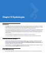
Chapter 13: Symbologies
Introduction ...................................................................................................................
Scanning Sequence Examples .....................................................................................
Errors While Scanning ..................................................................................................
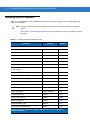
Symbology Default Parameters ....................................................................................
UPC/EAN ......................................................................................................................
Enable/Disable UPC-A/UPC-E ...............................................................................
Enable/Disable UPC-E1 ..........................................................................................
Enable/Disable EAN-13/JAN-13/EAN-8/JAN-8 .......................................................
Enable/Disable Bookland EAN ...............................................................................
Decode UPC/EAN Supplementals ..........................................................................
UPC/EAN Supplemental Redundancy ....................................................................
Transmit UPC-A/UPC-E/UPC-E1 Check Digit ........................................................
UPC-A Preamble ....................................................................................................
UPC-E Preamble ....................................................................................................
UPC-E1 Preamble ..................................................................................................
Convert UPC-E to UPC-A .......................................................................................
Convert UPC-E1 to UPC-A .....................................................................................
EAN Zero Extend ....................................................................................................
Bookland ISBN Format ...........................................................................................
UCC Coupon Extended Code .................................................................................
Code 128 ......................................................................................................................
Enable/Disable Code 128 .......................................................................................
Enable/Disable UCC/EAN-128 ...............................................................................
Enable/Disable ISBT 128 ........................................................................................
Code 128 Decode Performance .............................................................................
Code 128 Decode Performance Level ....................................................................
Code 39 ........................................................................................................................
Enable/Disable Code 39 .........................................................................................
Enable/Disable Trioptic Code 39 ............................................................................
Convert Code 39 to Code 32 ..................................................................................
Code 32 Prefix ........................................................................................................
Set Lengths for Code 39 .........................................................................................
Code 39 Check Digit Verification ............................................................................
Transmit Code 39 Check Digit ................................................................................
Enable/Disable Code 39 Full ASCII ........................................................................
Code 39 Buffering (Scan & Store) ..........................................................................
Code 39 Decode Performance ...............................................................................
Code 39 Decode Performance Level ......................................................................
Code 93 ........................................................................................................................
Enable/Disable Code 93 .........................................................................................
Set Lengths for Code 93 .........................................................................................
Code 11 ........................................................................................................................
Enable/Disable Code 11 .........................................................................................
Set Lengths for Code 11 .........................................................................................
Code 11 Check Digit Verification ............................................................................
Transmit Code 11 Check Digits ..............................................................................
Interleaved 2 of 5 (ITF) .................................................................................................
Enable/Disable Interleaved 2 of 5 ...........................................................................
Set Lengths for Interleaved 2 of 5 ...........................................................................
13-1
13-1
13-1
13-2
13-5
13-5
13-7
13-8
13-10
13-11
13-20
13-21
13-24
13-25
13-27
13-29
13-30
13-31
13-32
13-33
13-34
13-34
13-35
13-36
13-37
13-38
13-40
13-40
13-41
13-42
13-43
13-44
13-46
13-47
13-48
13-49
13-52
13-53
13-55
13-55
13-56
13-58
13-58
13-59
13-61
13-63
13-64
13-64
13-65
ix
x
Symbol LS7808 Horizontal Slot Scanner Product Reference Guide
I 2 of 5 Check Digit Verification ...............................................................................
Transmit I 2 of 5 Check Digit ...................................................................................
Convert I 2 of 5 to EAN-13 ......................................................................................
Discrete 2 of 5 (DTF) ....................................................................................................
Enable/Disable Discrete 2 of 5 ................................................................................
Set Lengths for Discrete 2 of 5 ...............................................................................
Codabar (NW - 7) .........................................................................................................
Enable/Disable Codabar .........................................................................................
Set Lengths for Codabar .........................................................................................
CLSI Editing ............................................................................................................
NOTIS Editing .........................................................................................................
GS1 DataBar (formerly Reduced Space Symbology) ...................................................
GS1 DataBar-14 .....................................................................................................
GS1 DataBar Limited ..............................................................................................
GS1 DataBar Expanded .........................................................................................
Convert GS1 DataBar to UPC/EAN ........................................................................
Symbology - Specific Security Levels ...........................................................................
Redundancy Level ..................................................................................................
Security Level .........................................................................................................
Bi-directional Redundancy ......................................................................................
Symbology - Intercharacter Gap ...................................................................................
13-67
13-69
13-70
13-71
13-71
13-72
13-75
13-75
13-76
13-79
13-80
13-81
13-81
13-82
13-83
13-84
13-85
13-85
13-88
13-90
13-91
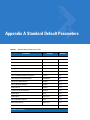
Appendix A: Standard Default Parameters
Appendix B: Programming Reference
Symbol Code Identifiers ................................................................................................ B-1
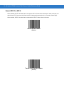
Appendix C: Sample Bar Codes
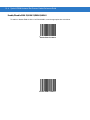
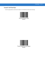
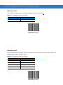
Code 39 ........................................................................................................................
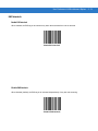
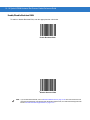
UPC/EAN ......................................................................................................................
UPC-A, 100 % .........................................................................................................
EAN-13, 100 % .......................................................................................................
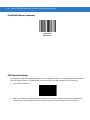
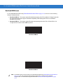
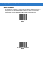
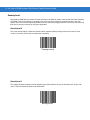
Code 128 ......................................................................................................................
Interleaved 2 of 5 ..........................................................................................................
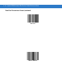
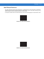
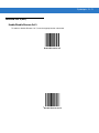
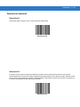
GS1 DataBar ................................................................................................................
GS1 DataBar Expanded .........................................................................................
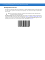
GS1 DataBar Limited ..............................................................................................
GS1 DataBar-14 .....................................................................................................
C-1
C-2
C-2
C-2
C-3
C-3
C-4
C-4
C-5
C-6
Table of Contents
Appendix D: Numeric Bar Codes
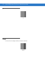
0 ....................................................................................................................................
1 ....................................................................................................................................
2 ....................................................................................................................................
3 ....................................................................................................................................
4 ....................................................................................................................................
5 ....................................................................................................................................
6 ....................................................................................................................................
7 ....................................................................................................................................
8 ....................................................................................................................................
9 ....................................................................................................................................
Cancel ...........................................................................................................................
Glossary
Index
D-1
D-2
D-2
D-3
D-3
D-4
D-4
D-5
D-5
D-6
D-6
xi
Table of Contents
xii
About This Guide
Introduction
The Symbol LS7808 Horizontal Slot Scanner Product Reference Guide provides general instructions for setting up,
operating, maintaining and troubleshooting the Symbol LS7808 scanner.
Chapter Descriptions
• Chapter 1, Getting Started provides a product overview and unpacking instructions.
• Chapter 2, Scanning describes parts of the scanner, beeper and LED definitions and how to use the scanner
in hand-held and hands-free modes.
• Chapter 3, Maintenance, Troubleshooting & Technical Specifications provides information on how to care for
the scanner, troubleshooting and technical specifications.
• Chapter 4, User Preferences & Miscellaneous Options provides the programming bar codes necessary for
selecting user preference features for the scanner.
• Chapter 5, Keyboard Wedge Interface provides information for setting up the scanner for Keyboard Wedge
operation.
• Chapter 6, RS-232 Interface provides information for setting up the scanner for RS-232 operation.
• Chapter 7, USB Interface provides information for setting up the scanner for USB operation.
• Chapter 8, IBM 468X/469X Interface provides information for setting up the scanner with IBM 468X/469X
POS systems.
• Chapter 9, Synapse Interface provides information for expanding the primary scanner’s capabilities by
connecting a (secondary) hand-held scanner using a Synapse adapter at the host port.
• Chapter 10, RS-232 Auxiliary Port provides information for setting up the auxiliary device.
• Chapter 11, Hand Held Laser Scanner Port provides information for expanding the primary scanner’s
capabilities by connecting a (secondary) hand-held scanner at the scanner port.
• Chapter 12, 123Scan describes this PC based scanner configuration tool and provides the bar code that
enables communication with the 123Scan program.
xiv
Symbol LS7808 Horizontal Slot Scanner Product Reference Guide
• Chapter 13, Symbologies describes all symbology features and provides the programming bar codes
necessary for selecting these features for the scanner.
• Appendix A, Standard Default Parameters provides a table of all host devices and miscellaneous scanner
defaults.
• Appendix B, Programming Reference provides a table of AIM code identifiers, ASCII character conversions and
keyboard maps.
• Appendix C, Sample Bar Codes includes sample bar codes.
• Appendix D, Numeric Bar Codes includes the numeric bar codes to scan for parameters requiring specific
numeric values.
Notational Conventions
The following conventions are used in this document:
• “Scanner” refers to the Symbol LS7808 Horizontal Slot.
• Italics are used to highlight chapters and sections in this and related documents.
• Bold text is used to highlight the following:
• key names on a keypad.
• button names on a screen.
• bullets (•) indicate:
• action items.
• lists of alternatives.
• lists of required steps that are not necessarily sequential.
• Sequential lists (e.g., those that describe step-by-step procedures) appear as numbered lists.
• Throughout the programming bar code menus, asterisks (*) are used to denote default parameter settings.
* Indicates Default
*Baud Rate 9600
Feature/Option
About This Guide
xv
Related Publications
• Symbol LS7808 Quick Reference Guide, p/n 72-73950-xx, provides general information to help the user get
started with the scanner. It includes basic set-up and operation instructions.
• Symbol LS7808-SR20007TCR Mounting Instructions and EAS Installation Quick Reference Guide,
p/n 72-95668-xx, provides scanning and mounting information for the Symbol LS7808-SR20007TCR
horizontal slot scanner, and installation instructions for the EAS kit.
• Advanced Data Formatting Programmer Guide, p/n 72-69680-xx, provides bar codes for advanced
programming of a Motorola scanner, and instructions for using them.
For the latest versions of all guides, go to: http://www.symbol.com/manuals.
Service Information
If you have a problem with your equipment, contact Motorola Enterprise Mobility Support for your region. Go to
http://www.symbol.com/contactsupport. If you purchased your Motorola product from a Motorola Business Partner,
contact that Business Partner for service.
Before contacting, have the model number and serial number at hand. If your problem cannot be solved by the
Motorola Enterprise Mobility Support, you may need to return your equipment for servicing and you will be given
specific directions.
Motorola is not responsible for any damages incurred during shipment if the approved shipping container is not
used. Shipping the units improperly can possibly void the warranty.
xvi
Symbol LS7808 Horizontal Slot Scanner Product Reference Guide
Chapter 1 Getting Started
Introduction
The Symbol LS7808 horizontal slot scanner is a high performance, omni-directional scanner that supports high
throughput applications at the point of sale (POS). The scanner reads all retail symbologies and has multi-interface
capability to interface to all popular POS devices. The scanner is designed for horizontal in-counter mounting and
allows slide-through scanning of items enhancing productivity and throughput. The scanner has an integrated radio
frequency-based Electronic Article Surveillance (EAS) system for deactivating tags.
The Symbol LS7808 scanner provides connection for an optional Synapse™ compatible hand-held scanner such
as the Symbol LS1203, LS2208, LS4208 or DS6608. The hand-held scanner allows you to scan heavy items
without lifting them.
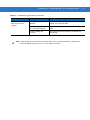
Configurations
Table 1-1 Symbol LS7808 Horizontal Slot Scanner Configurations
Configurations
Features
Symbol LS7808-SR20007TCR
Standard (tin oxide) glass window; twilight black;
Checkpoint® EAS; RoHS compliant
Symbol LS7808-SR20009SCR
Scratch proof (sapphire) glass window; stainless steel bezel top;
Checkpoint® EAS; RoHS compliant.
Symbol LS7808-SR22009SCR
Scratch proof (sapphire) glass window; stainless steel bezel top;
Checkpoint® EAS; RoHS compliant; Remote Scanner Management
(RSM) ready “out of the box.”
All models require a stainless steel in-counter mounting kit (p/n 12-17206-02R). See the
Mounting Instructions and EAS Installation Guide for mounting and installation instructions.
1-2
Symbol LS7808 Horizontal Slot Scanner Product Reference Guide
NOTE
Scanner kit configurations include power cord adapters, host interface cables, product CD and Quick
Reference Guide.
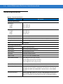
Interfaces
The Symbol LS7808 scanner supports the following interfaces:
• TTL-level RS-232 connection to a host. Set up communication between the scanner and the host either by
scanning bar code menus or using the Windows-based programming tool 123Scan.
• Keyboard Wedge connection to a host. The host interprets scanned data as keystrokes.
International keyboards supported:
• Windows™ environment: North American, German, French, Spanish, Italian, Swedish, UK English,
Brazilian/Portuguese and Japanese.
• Windows XP/2000™ environment: French Canadian
• Windows 95/98 environment: French Canadian
• Connection to IBM 468X/469X hosts. Set up communication between the scanner and the IBM terminal
either by scanning bar code menus or using the Windows-based programming tool 123Scan.
• USB connection to a host. The scanner autodetects a USB host and defaults to the HID keyboard interface
type. To select other USB interface types, scan programming bar code menus or use the Windows-based
programming tool 123Scan.
• International Keyboards supported (for Windows™ environment): North America, German, French,
French International, Spanish, Italian, Swedish, British and Japanese.
• Synapse capability that allows the scanner to connect to a wide variety of host systems using a Synapse and
Synapse adapter cable. The scanner autodetects Synapse.
Getting Started
1-3
Unpacking the Scanner
Remove the scanner from its packing and inspect it for damage. The following items are included in the package:
• Scanner
• Symbol LS7808 Quick Reference Guide (p/n 72-73950-xx)
If any items are missing or damaged, contact the Customer Interaction Center. KEEP THE PACKING. It is the
approved shipping container and should be used if it is ever necessary to return the equipment for servicing.
Accessories
The following accessories are available from Motorola. See your Motorola representative or re-seller for ordering
information.
Required Accessories
• Cables
• Host interface cable
or
• Synapse Adapter and Synapse cable.
• p/n 25-69783-01R
• p/n 25-69784-01R
NOTE
Y cables must be used with peripherals into the scanner’s secondary scanner port or auxiliary port. An
external power supply is required when connecting a secondary scanner.
• Stainless Steel In-counter Mounting Bucket (p/n 12-17206-02R)
Optional Accessories
• Universal Power Supply (110-250V), if required (p/n 50-14000-058R)
Some host terminals (e.g., IBM 46xx Series) supply power to the scanner, so an external power supply is not
required. Contact a Motorola representative for more information.
• U.S. Power Cord adapter for 50-14000-058R (p/n 23844-00-00R)
• EAS Interlock Cable
• P/n 25-88076-01R
or
• Molex p/n
• 51065-0400 (4 conductor housing)
• 50212-8100 (crimp pin)
• 63811-1200 (crimp tool)
• 57105-6000 (pin extraction tool)
• Replacement Glass/Bezel (Standard Tin Oxide Glass) - for LS7808-SR20007TCR (p/n KT-87295-01R)
NOTE
If you are replacing a Symbol LS5800-I200TC or LS5800-I200TN scanner with the Symbol
LS7808-SR20007TCR or LS7808-SR2X009SCR, mounting buckets are interchangeable.
1-4
Symbol LS7808 Horizontal Slot Scanner Product Reference Guide
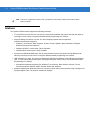
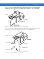
Views/Parts
LED Indicator
Connector Cover
(Connector Ports behind
Connector Cover)
Bucket
Speaker
Figure 1-1 Symbol LS7808 Scanner Views/Parts
Getting Started
1-5
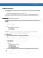
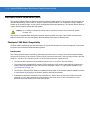
Views/Parts (continued)
Secondary
Scanner Port
Host Port
EAS
Power
Port
EAS Interlock
Port (Behind
Label)
Connector
Cover
RS-232
Auxiliary
Port
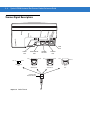
Figure 1-2 Symbol LS7808 Scanner Views/Parts
Input/Output Ports
See Figure 1-2 for port locations.
Power Port. When external power is required, the input to this port is 5V @ 500 mA maximum, 390 mA nominal,
with no peripherals, 5V @ 1.5A maximum with peripherals.
Host Port. A 10-pin modular connector. Plug the host cable, the Synapse Adapter cable, or Synapse Power
Regulator cable into this port.
Secondary (Hand-Held) Scanner Port. A 6-pin modular connector. Plug a Synapse-compatible hand-held laser
scanner, such as the Symbol LS1203, LS2208, LS4208 or DS6608 into this port. This scanner can
program the Symbol LS7808 and adapts to LS7808 decode parameters (i.e., code types, lengths and check digits).
RS-232 Aux Port. A 10-pin modular connector. Use this as an auxiliary port to connect non-STI hand-held
scanners or serial devices such as a scale or magstripe reader. Current draw on this port should not exceed 200
mA. The total current draw on the hand-held port and scanner port should not exceed 700 mA.
NOTE
For detailed connection information, see the applicable host chapter.
1-6
Symbol LS7808 Horizontal Slot Scanner Product Reference Guide
Setting Up the Scanner
Power Options
Depending on the peripherals used, the scanner receives power from one of two sources:
• Via the host through the host cable: If the host can supply 500mA of power, the host cable is less than 8.5’
long and there are no peripheral devices in the configuration.
• Via an external power supply: When the host cannot provide sufficient power, the host cable length is more
than 8.5’ long, or a peripheral device is connected to the hand-held and/or scanner ports. The external supply
connects directly into the DC port or through a host cable with an adapter or Y-connection.
When the scanner receives power, the green LED lights and three short high beeps sound, indicating that the
scanner is operational.
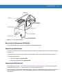
Connecting the Host and Peripheral Cables
Connect the cables in the following order (see Figure 1-3):
CAUTION
The order of cable insertion is extremely important. Ensure the steps below are followed in order. For
a cable with a Y-connector (containing both power and interface connectors), connect the
power and interface cables to the appropriate ports.
1.
Plug the host interface cable modular connector into the host port on the scanner.
2.
Connect peripheral device cables to the correct ports on the scanner and the other end of the cables to the
peripherals.
3.
Connect the external power supply to the host cable, adapter, or power port (if needed, see Power Options).
4.
Connect the host cable to the host.
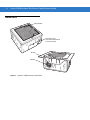
Getting Started
1-7
Secondary
Scanner Port
Host Port
EAS
Power
Port
EAS Interlock
Port (Behind
Label)
Connector
Cover
RS-232
Auxiliary
Port
Figure 1-3 Scanner Connections
NOTE
Different hosts require different cables. The connectors illustrated in each host chapter are examples only.
Connectors may be different from those illustrated, but the steps to connect the scanner are the same.
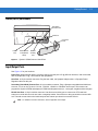
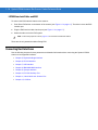
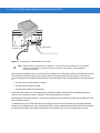
Routing Cables
After placing the cable connectors in the appropriate scanner ports (see Figure 1-3 on page 1-7), reattach the
scanner connector cover. Route the cables through the two openings in the connector cover and tighten the screws
to secure the cover and keep the cables in place.
Cable Routing
Openings
Figure 1-4 Cable Routing
1-8
Symbol LS7808 Horizontal Slot Scanner Product Reference Guide
Removing Cables
To remove the connector cables:
1.
Access the installed scanner connector cover under the counter.
2.
Use a screwdriver or coin to unscrew the connector cover screws.
3.
Remove the connector cover.
4.
Unplug connected cables as follows:
• host cable modular connector - depress the connector clip with the tip of a screwdriver, or a paper clip,
and gently pull back.
• RS-232 auxilliary and scanner cables - depress the connector clip with the tip of a screwdriver, or a paper
clip, and gently pull back.
• power and EAS connectors - gently pull the connectors from the ports.
5.
Follow the steps for Connecting the Host and Peripheral Cables on page 1-6 to connect new cables.
6.
Reattach the scanner connector cover and route the cables through the two openings in the connector cover.
Tighten the screws to secure the cover and keep the cables in place.
Getting Started
1-9
Configuring the Scanner
To configure the scanner, use the bar codes in this guide or use the 123Scan configuration program.
See Chapter 4, User Preferences & Miscellaneous Options for information about programming the scanner using
bar code menus. See Chapter 12, 123Scan to configure the scanner using this configuration program. A help file is
available in the program.
The scanner supports RS-232, IBM 468X/469X, Keyboard Wedge, USB and Synapse to interface with a host
system. Each host-specific chapter describes how to set up each of these connections.
Synchronization of Settings
Host Requested Setting Changes
The IBM 4683, IBM Handheld USB and Synapse hosts can change a limited set of the scanner's settings. The
123Scan host maintains all the Symbol LS7808 scanner's settings. When a handheld scanner is connected, all
setting changes the host requests are processed by both the LS7808 scanner and the handheld scanner. Only a
limited set of handheld scanner settings are updated, including code type enable/disable, code type lengths,
beeper settings, redundancy and security level settings.
For example, if the IBM 4683 host requests to disable the Code 39 symbology, then Code 39 is disabled on both
the Symbol LS7808 scanner and the handheld scanner.
Bar Code Menu Symbols Scanned on the Symbol LS7808 Scanner
A limited set of bar code menu symbols scanned on the Symbol LS7808 scanner are synchronized with the
handheld scanner (if attached). These settings are code type enable/disable, code type lengths, beeper settings,
redundancy and security level settings.
Bar Code Menu Symbols Scanned on the Handheld Scanner
By default, the handheld scanner can program the Symbol LS7808 scanner's settings (primary only mode).
The handheld programming mode setting All Scanners Mode allows programming both the handheld scanner and
the Symbol LS7808 scanner simultaneously. In this mode, scanning Set Defaults returns the LS7808 scanner to
the default mode.
Another setting isolates the handheld scanner so that the bar code menu symbols scanned apply only to the
handheld scanner. To return to the default functionality change the setting on the Symbol LS7808 scanner directly.
Regardless of the handheld scanner mode, all parameter changes requested by the host and via bar code menu
settings on the Symbol LS7808 scanner are synchronized on the handheld scanner for applicable settings.
Beeper Tone and Volume
To change the tone and volume of the scanner beeper, scan the bar codes beginning on page 4-3. See Beeper
Definitions on page 2-3 for more information.
1 - 10 Symbol LS7808 Horizontal Slot Scanner Product Reference Guide
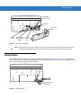
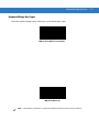
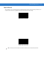
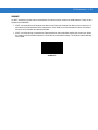
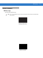
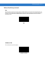
Installation
The Symbol LS7808 is designed to be installed in the counter, with the face of the scanner flush with the counter
top.
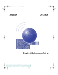
Figure 1-5 shows a typical layout. The dotted area depicts the active scan area and the arrow shows the optimal
direction of product flow. The scanner’s active scan zone extends about 6 in. (15.24 cm) above the window
and is angled at approximately 38° from the counter.
Product Flow
Scanner
Window
Figure 1-5 Active Scan Area
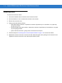
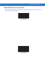
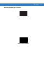
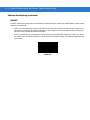
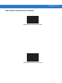
Typical Layouts
Figure 1-6 shows a typical Symbol LS7808 installation without an auxilliary scanner and EAS. For best operating
results, locate the power supply at least 4 in. (10.16 cm) below the scanner chassis or 2 in. (5.08 cm) away
laterally.
Host
Scanner
Synapse Cable
(Optional)
Host Interface Cable
Power Supply (optional)
Figure 1-6 Typical Symbol LS7808 Installation
Getting Started 1 - 11
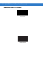
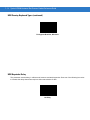
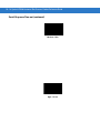
Figure 1-7 shows a typical LS7808 installation with an auxilliary scanner connected. For best operating results,
locate the power supply at least 4 in. (10.16 cm) below the scanner chassis or 2 in. (5.08 cm) away laterally.
Host
Scanner
Synapse Cable
(Optional)
Host Interface Cable
Power Supply
Figure 1-7 Typical Symbol LS7808 Installation with an Auxilliary Scanner
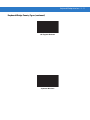
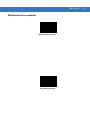
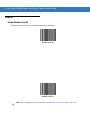
Figure 1-8 shows a typical Symbol LS7808 installation with EAS. For best operating results, locate the power
supply at least 4 in. (10.16 cm) below the scanner chassis or 2 in. (5.08 cm) away laterally.
Host
Scanner
Synapse Cable
(Optional)
EAS Control Cable
Host “Y” Cable
EAS
Antenna Box
Power Cable (optional)
EAS Control Box
Power Supply (optional)
Figure 1-8 Typical Symbol LS7808 Installation with EAS
1 - 12 Symbol LS7808 Horizontal Slot Scanner Product Reference Guide
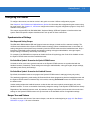
Installing the Symbol LS7808
The Symbol LS7808 requires an in-counter mounting kit. There are two mounting options.
Option A - Resting on the Counter Top
1.
Cut a hole in the counter 6.26 in. (159 mm) square.
Counter Hole
6.26
6.81 in. ±0.06
159
173 mm ±1.5
7.91 in.
201 mm
~3.5 in.
89 mm
Figure 1-9 Symbol LS7808 Option A
2.
Place the bucket into the hole.
3.
Unscrew and remove the scanner connector cover.
4.
Place the scanner on the counter near the bucket.
5.
Route the cables from beneath the hole and attach to the scanner as shown in Typical Layouts on page 1-10.
6.
Reattach the connector cover and tighten the screws.
7.
Lower the scanner into the bucket.
IMPORTANT Always reattach the connector cover and tighten the screws after all cables are connected to the
scanner ports. The connector cover ensures that all cables are properly situated and connections are
secure.
Getting Started 1 - 13
Option B - Flush with the Counter Top
1.
On the counter top, measure two concentric squares: an inside square of 6.81 in. (173 mm) and an outside
square of 7.91 in. (201 mm) (Figure 1-10).
2.
Cut out the 6.81 in. (173 mm) inner square.
3.
With a router set to a depth of .05 in. (1.2 mm), route out the outside square. The corner radius should not
exceed 0.2 in. (5 mm). Ensure the outside square is concentric with the inside square.
R 0.20 in. max
R 5 mm max
Counter Hole
0.39 in min
10 mm min
0.27 in
6.8 mm
0.05 in
1.2 mm
7.91 in.
201 mm
~3.5 in.
89 mm
6.81 in. ±0.06
173 mm ±1.5
7.91 in.
201 mm
0.39 in min
10 mm min
7.91 in. min
201 mm min
~3.5 in.
89 mm
Figure 1-10 Symbol LS7808 Option B
4.
Place the bucket into the hole.
5.
Unscrew and remove the scanner connector cover.
6.
Place the scanner on the counter near the bucket.
7.
Route the cables from beneath the hole and attach to the scanner as shown in Typical Layouts on page 1-10.
8.
Reattach the connector cover and tighten the screws.
IMPORTANT Always reattach the connector cover and tighten the screws after all cables are connected to the
scanner ports. The connector cover ensures that all cables are properly situated and connections are
secure.
9.
Lower the scanner into the bucket.
1 - 14 Symbol LS7808 Horizontal Slot Scanner Product Reference Guide
Electronic Article Surveillance (EAS)
The Symbol LS7808 includes an Electronic Article Surveillance (EAS) antenna. The scanner and EAS system can
operate independently of each other, or using an exclusive interlock feature. The deactivation range is mapped
suitable to the scanning range, so both can be accomplished almost simultaneously. The interlock feature requires
a good decode signal to activate the EAS system.
CAUTION
Do not attempt to activate the interlock feature. Activation instructions are for a Motorola qualified
technician only.
The scanner’s integrated EAS deactivation antenna requires an EAS host cable. This Y-cable connects to the
scanner’s host port at one end and splits to the host and the EAS system at the other end.
Checkpoint® EAS Model Compatibility
The EAS cable is intended for use with Checkpoint CP-VII and CP-IX systems. It does not support CP-IV and other
low-power receiver-based EAS deactivation systems.
Considerations
The Checkpoint EAS system operates by generating a periodic burst of energy which deactivates EAS tags
brought into proximity of the scanner. Unless proper precautions are taken, this field may interfere with the
scanner’s operation.The following criteria must be observed when installing EAS:
• The antenna box must be as far as possible (minimum 6 in. or 15.24 cm) from the scanner.
• The scanner (with integrated EAS antenna), EAS antenna box, EAS control cable and EAS controller box
must be as far as possible from the scanner’s host and power cables. For a typical EAS installation, see
Typical Layouts on page 1-10.
• The counter in which the EAS antenna is installed must be made of non-metallic materials. Metallic counters
or metal objects in proximity to the scanner interfere with EAS deactivation.
• If two antenna boxes are connected to the controller box, each of them must be connected to a scanner
(antenna). If one is left unconnected, communications errors may occur. If only one antenna is in use,
disconnect the other antenna box at the controller box.
Getting Started 1 - 15
Host
Scanner
Synapse Cable
(Optional)
EAS Control Cable
Host “Y” Cable
EAS
Antenna Box
Power Cable (optional)
EAS Control Box
Power Supply (optional)
Figure 1-11 Typical EAS Installation
Deactivation for Sensormatic EAS System
To interface to Sensormatic systems, contact Motorola Product Management.
Connecting the EAS Antenna
A host host interface cable with EAS leads from Motorola is required. The EAS leads are connected by Checkpoint
Systems, Inc.
Contact your local Checkpoint representative to install the EAS cable to the Checkpoint Deactivation System.
To contact a representative:
• In the United States call: 800-257-5540
• Outside the United States call: (609) 848-1800.
Connecting the EAS Interlock
The parameters in Chapter 4, User Preferences & Miscellaneous Options allow you to activate the EAS system
independent of the scanner, or combine the two in an exclusive interlock feature.
The interlock feature discourages “sweetheart shopping.” These are instances where some customers are favored
and not all items are scanned. The interlock prohibits the deactivation of the EAS tag without the item being
scanned first.
1 - 16 Symbol LS7808 Horizontal Slot Scanner Product Reference Guide
LS7808 Interlock Cable and EAS
To connect the EAS interlock feature to the scanner:
1.
Peel off the EAS sticker on the bottom of the scanner (see Figure 1-2 on page 1-5). The sticker covers the EAS
interlock port.
2.
Plug the EAS interlock cable into the port (see Figure 1-3 on page 1-7).
3.
Attach the other end to the EAS system.
NOTE
Ensure the proper bar code on page 4-13 is scanned to activate this feature.
These are the only standard models offering EAS.
Connecting Host Interfaces
See the following chapters for host parameters and detailed information about connecting the Symbol LS7808
scanner to its supported interfaces.
• Chapter 5, Keyboard Wedge Interface
• Chapter 6, RS-232 Interface
• Chapter 7, USB Interface
• Chapter 8, IBM 468X/469X Interface
• Chapter 9, Synapse Interface
• Chapter 10, RS-232 Auxiliary Port
• Chapter 11, Hand Held Laser Scanner Port
• Chapter 12, 123Scan.
Chapter 2 Scanning
Introduction
This chapter covers the techniques involved in scanning bar codes, beeper and LED definitions and general
instructions and tips about scanning. See Chapter 1, Getting Started for information on scanner components and
connecting host cables and the power supply.
Active Scan Area
The active scan area is optimized to scan items as they move in the direction of the scan arrow.
The dotted area in Figure 2-1 depicts the active scan area and the arrow shows the optimal direction of product
flow. The scanner’s active scan zone extends about 6 in. (15.24 cm) above the window and is angled at
approximately 38° from the counter.
Product Flow
Scanner
Window
Figure 2-1 Active Scan Area
2-2
Symbol LS7808 Horizontal Slot Scanner Product Reference Guide
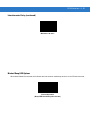
Scanning Bar Codes
Install and program the scanner. (See each host chapter and Chapter 4, User Preferences & Miscellaneous
Options, Chapter 13, Symbologies, and Advanced Data Formatting for instructions on programming the scanner.)
For assistance, contact the local supplier or see Service Information.
For the best scanning performance, the counter top or surface area covered by the active scan area should be a
light, solid color. Avoid designs (e.g., stripes or patterns).
To scan a bar code:
1.
Ensure all cable connections are secure.
2.
Orient the item with the bar code facing the scanner window, or presented vertically and facing forward.
3.
Move the item through the active scan area in the direction of the scan arrow.
Scanner Window
Product Flow
Scan Arrows
Figure 2-2 Scanning a Bar Code
4.
Upon successful decode, the scanner beeps and the green LED flashes.
For more information on beeper definitions, see Table 2-1.
Scanning
2-3
Beeper
The scanner has an internal beeper to signal a good decode or provide other information (see Table 2-1). An
external beeper can also be connected to the RS-232C port. Either or both of these beepers can be enabled or
disabled through the use of bar code menus.
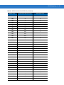
Beeper Definitions
The scanner communicates by emitting different beeper sequences. Table 2-1 defines beeper sequences that
occur during normal scanning and while programming the scanner.
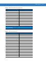
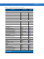
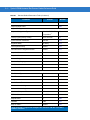
Table 2-1 Standard Beeper Definitions
Beeper Sequence
Indication
Standard Use
3 short high beeps
Power up.
High beep
A bar code was decoded (if decode beeper is enabled).
4 long low beeps
A transmission error was detected in a scanned symbol. The data is
ignored. This occurs if the scanner is not properly configured. Check
option settings.
When scanning bar code menu symbols, indicates the handheld scanner
does not support the setting; use the primary scanner instead.
5 low beeps
Conversion or format error.
High-high-high-low beeps
RS-232 receive error on RS-232 host or RS-232 auxiliary port.
Parameter Menu Scanning
Short high beep
Correct entry scanned or correct menu sequence performed.
Low/high beep
Input error, incorrect bar code or “Cancel” scanned, wrong entry, incorrect
bar code programming sequence; remain in program mode.
High/low beep
Keyboard parameter selected. Enter value using bar code keypad.
High/low/high/low beep
Successful program exit with change in the parameter setting.
Low/high/low/high beep
Out of host parameter storage space. Scan Set Default Parameter on
page 4-3.
Low/low/low/low beep
Unsupported parameter.
Code 39 Buffering
High/low beep
New Code 39 data was entered into the buffer.
3 long high beeps
Code 39 buffer is full.
Low/high/low beep
The Code 39 buffer was erased or there was an attempt to clear or
transmit an empty buffer.
Low/high beep
A successful transmission of buffered data.
2-4
Symbol LS7808 Horizontal Slot Scanner Product Reference Guide
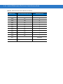
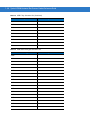
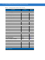
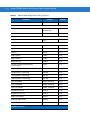
Table 2-1 Standard Beeper Definitions (Continued)
Beeper Sequence
Indication
Host Specific
USB only
4 short high beeps
Scanner has not completed initialization. Wait several seconds and scan
again.
Scanner emits a power-up
beep after scanning a
a USB Device Type.
Communication with the bus must be established before the scanner can
operate at the highest power level.
This power-up beep occurs
more than once.
The USB bus may put the scanner in a state where power to the scanner
is cycled on and off more than once. This is normal and usually happens
when the PC cold boots.
RS-232 Host only
High beep
A <BEL> character is received and Beep on <BEL> is enabled.
RS-232 Auxiliary Port only
High beep
A complete block of data was received and sent to the host, either due to a
carriage return or because the two-second serial response timeout has
elapsed.
4 long low beeps
A data overrun condition has occurred. Do not scan data from other ports
when large amounts of data are sent to the RS-232 auxiliary port.
Low Power Mode
After a period of inactivity, the scanner enters a low power or sleep mode. After ten seconds of inactivity, the laser
pulses at a 50% rate, then drops to 3% after a specified time.
To change the default time of 30 minutes, scan the appropriate bar code on page 4-9 (Time Delay to Low Power
Mode).
Scanning
2-5
LED Definitions
The scanner also communicates via an LED (see Figure 1-2). Table 2-2 defines LED indications that occur during
scanning.
Table 2-2 Standard LED Definitions
LED
Indication
Off
No power is applied to the scanner.
Green
The scanner is on and “ready to scan.”
Momentary flash
A bar code was successfully decoded.
Slow continuous red flashing,
green on
The scanner is in programming mode.
Fast continuous red flashing,
green on
There is an internal problem; the laser is shut off for
regulatory reasons.
Green on (and laser blinking)
Scanner is in low power blink mode.
Red and green on
Scanner is in low power (sleep) mode.
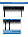
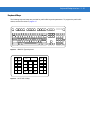
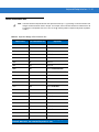
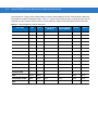
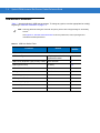
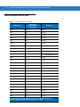
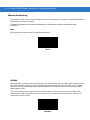
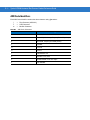
Decode Distances
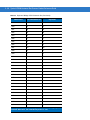
Table 2-3 specifies the distances within which the scanner recognizes bar codes.
Table 2-3
Symbol LS7808 Decode Distances
Symbol Density/
Bar Code Type
Guaranteed Working Ranges
Near
Far
5.0 mil*
Code 39
0.0 in
0.0 cm
0.5 in
1.27 cm
7.8 mil
UPC-A
0.0 in
0.0 cm
4.0 in
10.16 cm
10.4 mil
UPC-A
0.0 in
0.0 cm
5.0 in
12.7 cm
13 mil
UPC-A
0.0 in
0.0 cm
7.0 in
17.78 cm
13 mil, 25% MRD
UPC-A
0.0 in
0.0 cm
7.0 in
17.78 cm
*5.0 mil symbol distance measured in ladder orientation;
other symbols represent picket orientation.
2-6
Symbol LS7808 Horizontal Slot Scanner Product Reference Guide
Chapter 3 Maintenance, Troubleshooting &
Technical Specifications
Introduction
This chapter covers suggested scanner maintenance, troubleshooting, technical specifications and signal
descriptions (pinouts).
Maintenance
Cleaning the exit window is the only maintenance required. A dirty window can affect scanning accuracy.
• Do not allow abrasive material to touch the window.
• Remove dirt particles with a damp cloth.
• Wipe the window using a tissue moistened with ammonia/water.
• Do not spray water or other cleaning liquids directly into the window.
To clean the scan window:
1.
Insert a coin into the large screw heads on the front of the scanner and turn counter-clockwise.
2.
Lift off the window.
3.
Wipe clean the underside of the upper window.
4.
Wipe clean the top surface of the lower window.
5.
Re-install the top cover by tightening the two large screws.
3-2
Symbol LS7808 Horizontal Slot Scanner Product Reference Guide
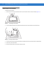
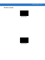
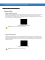
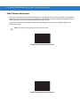
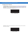
Replacing the Scan Window
To replace the scan window:
1.
Insert a coin into the large screw heads on the front of the scanner and turn counter-clockwise (Figure 3-1).
Figure 3-1 . Unscrewing the Front Panel
2.
Lift off the window using the screw heads and carefully remove the scan window from the window frame.
Figure 3-2 Removing the Window Glass
3.
Lift off the scan window using the screw heads and carefully remove the scan window from the window frame.
4.
Insert a new, clean scan window.
5.
Secure the window frame to the scanner using two screws.
Maintenance, Troubleshooting & Technical Specifications
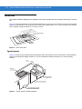
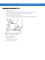
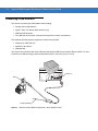
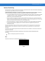
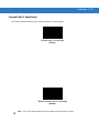
Replacing the Scanner Body
To replace the scanner body:
1.
Remove the scan window by following the steps in Replacing the Scan Window on page 3-2.
2.
Unsrew the screws on the connector cover and remove the connector cover.
3.
Disconnect all cables from the connector ports.
4.
Lift out the scanner body by pulling up on the two lift tabs on either side of the scanner body.
Figure 3-3 Removing the Scanner Body
5.
Insert a new scanner body.
6.
Replace the scan winow.
7.
Reconnect the connector cables.
8.
Reconnect the connector cover.
3-3
3-4
Symbol LS7808 Horizontal Slot Scanner Product Reference Guide
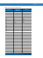
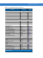
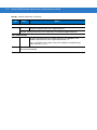
Troubleshooting
Table 3-1 Troubleshooting the Scanner
Problem
Possible Causes
Possible Solutions
No power to the scanner.
Ensure the host has power and is on. If the scanner
uses a separate power supply, ensure it’s connected to
a working AC outlet.
Power-up sequence is incorrect.
Interface cable is not
properly connected.
Check for loose cable connections.
Scanner is not programmed
to read the bar code type.
Ensure scanner is programmed to read the bar code
type you are scanning.
Bar code is damaged.
Try scanning other bar codes of the same bar code
type.
Bar code is too far from
scanner.
Move the bar code closer to the scanner.
The host has disabled
scanning or overridden
parameter settings.
See the technical person in charge of scanning.
Bar code is decoded, but
not transmitted to the host.
Scanner is not programmed
for the correct host type.
Scan the appropriate host type bar code.
Scanned data is
incorrectly displayed on
the host.
Scanner is not programmed
to work with the host. Check
scanner host type
parameters or editing
options.
Ensure proper host is selected.
For RS-232, ensure the scanner’s communication
parameters match the host’s settings.
For keyboard wedge, ensure scanner is programmed
with the correct country code and that the CAPS LOCK
key is off.
Ensure editing options (e.g., UPCE-to-UPCA
Conversion) are properly programmed.
Although the green and
red LEDs are on, the
scanner does not produce
the omni-directional scan
pattern.
Scanner has gone into low
power “Motor Sleep” mode.
Move a bar coded item over the active scan area to
awaken the unit.
USB or Synapse host not
functioning properly.
Scanner does not recognize
host.
Remove and reinsert external power supply to force
cable to autodetect correct host.
An error occurs when
connecting to a USB host.
Cables were installed in the
incorrect order.
See Connecting the Host and Peripheral Cables on
page 1-6 for the correct order of insertion.
Handheld scanner does
not power on.
External power supply is not
attached.
Connect an external power supply directly to the
scanner, not to the host cable.
The omni-line scan pattern
does not display when you
follow the directions for
installing the host cable on
page 1-6.
Scan line(s) display, but
bar code cannot be read.
Maintenance, Troubleshooting & Technical Specifications
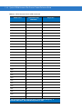
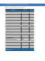
Table 3-1 Troubleshooting the Scanner (Continued)
Problem
Auxiliary RS-232 device
data is not received
properly.
NOTE
Possible Causes
Possible Solutions
External power supply is not
attached.
Connect an external power supply directly to the
scanner, not to the host cable.
Auxiliary device supplies
TTL level RS-232 signals.
Use a device that supports standard RS-232 signal
levels.
Auxiliary settings are
incorrect.
Use auxiliary RS-232 port settings, not the RS-232
host settings.
If after performing these checks the symbol still does not scan, contact the distributor or call Motorola
Enterprise Mobility Support. See page xv for the telephone numbers.
3-5
3-6
Symbol LS7808 Horizontal Slot Scanner Product Reference Guide
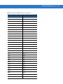
Technical Specifications
Table 3-2 Technical Specifications
Item
Description
Physical Characteristics
Dimensions:
Length
Width
Depth
6.0 in. (15.2 cm)
6.0 in. (15.2 cm)
3.1 in. (7.6 cm)
Bucket Dimensions
Length
Width
Depth
7.87 (19.9 cm)
7.87 (19.9 cm)
3.16 (8.0 cm)
Weight
1.9 lbs. (862 g)
Power Source (nominal)
Power drawn from host terminal or external power supply; depends on host type.
Voltage/Current
5.0 Volts ±5% @ 450mA
Color
Twilight Black
Performance Characteristics
Light Source
670nm visible laser diode
Print Contrast
25% minimum reflective difference
Scan Patterns
18 interlocking scan lines
Scan Rate
1,800 scan lines per second
Depth of Field
0 to 6 in./ 0 to 15cm, UPC/EAN 100%
Typical Working Range
5 mil: (38%) 0 to 0.5 in. (0 to 1.27 cm)
7.8 mil: (60%) 0 to 4.0 in. (0 to 10.16 cm)
10.4 mil: (80%) 0 to 5.0 in. (0 to 12.7 cm)
13 mil: (100%) 0 to 7.0 in. (0 to 17.8 cm)
Minimum Resolution
5 mil
Decode Capability
UPC-A, UPC-E, UPC-E1, EAN 8/13, JAN 8/13, UPC/EAN with Supplementals,
Code 39, Code 39 Full ASCII, Interleaved 2 of 5, Discrete 2 of 5, Code 128,
UCC/EAN 128, ISBT 128, Codabar/NW7, Code 93, Code 11, GS1 DataBar
Variants
Interfaces Supported
RS-232C (Standard, Nixdorf, ICL, & Fujitsu); IBM 468x/469x; Keyboard Wedge;
USB (Standard, IBM SurePOS, Macintosh); Synapse adaptive connectivity
allows for connectivity to all of the above plus many non-standard interfaces.
Maintenance, Troubleshooting & Technical Specifications
Table 3-2 Technical Specifications (Continued)
Item
Description
User Environment
Operating Temperature
32° to 104°F (0° to 40°C)
Storage Temperature
-40° to 140°F (-40° to 60°C)
Humidity
5% to 95% (non-condensing)
Ambient Light Immunity
Immune to normal artificial indoor and natural outdoor (direct sunlight) lighting
conditions.
Fluorescent, Incandescent, Mercury Vapor and Sodium Vapor: up to 450 ft
candles (4,844 Lux)
Sunlight: 8000 Ft Candles (86,111 Lux)
EAS Support
All units support Checkpoint Electronic Article Surveillance Antenna (EAS)
Regulatory
Electrical Safety
UL 60950-1, CSA C22.2 No. 60950-1
EN 60950-1, IEC 60950-1
Laser Safety
21CFR1040.10 Class IIa
EN 60825-1, IEC60825-1 Class 1
EMI/RFI
FCC Part 15 Class B, ICES-003 Class B
EN 55022 Class B, EN 55024
1
Refers to 100% UPC bar code (80% contrast) located 4 in. (10 cm) from the scanner.
3-7
3-8
Symbol LS7808 Horizontal Slot Scanner Product Reference Guide
Scanner Signal Descriptions
EAS
Host
Port
Power
Port
EAS Interlock
Port
Pin 1
Pin 1
Pin 10
Pin 4
EAS Interlock
Port
RS-232
Auxiliary Port
Interface cable
modular connector
Figure 3-4 Cable Pinouts
RS-232
Aux Port
Scanner
Port
Pin 1
Pin 6
Hand-Held
Scanner Port
Pin 1
Pin 10
Host
Port
Maintenance, Troubleshooting & Technical Specifications
The signal descriptions in Table 3-3 apply to the connector on the scanner and are for reference only.
Table 3-3 Scanner/Host Signal Pin-outs
Pin
IBM
Synapse
RS-232
Keyboard Wedge
USB
Download
1
Reserved
SynClock
Reserved
Reserved
Jump to Pin 6
Reserved
2
Power
Power
Power
Power
Power
Power
3
Ground
Ground
Ground
Ground
Ground
Ground
4
IBM_A(+)
Reserved
TxD
KeyClock
Reserved
TxD
5
Reserved
Reserved
RxD
TermData
D+
Reserved
6
IBM_B(-)
SynData
RTS
KeyData
Jump to Pin 1
RxD
7
Reserved
Reserved
CTS
TermClock
D-
Reserved
8
Reserved
Reserved
Reserved
Reserved
Reserved
Download
9
Reserved
Reserved
Reserved
Reserved
Reserved
Reserved
10
Reserved
Reserved
Reserved
Reserved
Reserved
Reserved
Table 3-4 RS-232 Auxiliary Port Pinouts
Pin #
Signal
Unterminated
Wire*
Description
1
-
2
DTR
Brown
Output, Data Terminal Ready
3
RXD
Orange
Input, Received Data
4
VCC
Red
5 volts
5
RTS
Green
Output, Ready to Send
6
GND
Black
Ground
7
CTS
Purple
Input, Clear to Send
8
-
9
TXD
Yellow
Output, Transmitted Data
10
-
*The RS-232 port can power a connected device, such as a scale, magstripe
reader, or hand-held scanner. The device’s mating connector is wired to the
end of an unterminated cable. To build an unterminated cable for this port,
refer to the pinout information in this table. The following table lists
unterminated wires and their functions.
If the device attached to the RS-232 Auxiliary Port is self-powered, do not
connect the red wire (VCC) to the mating connector. This prevents the device
from back-powering the Symbol LS7808.
3-9
3 - 10 Symbol LS7808 Horizontal Slot Scanner Product Reference Guide
Table 3-5 Hand-Held Scanner Port Pinouts
Pin 1
SYNDATA
Pin 2
SYNCLK
Pin 3
VCC
Pin 4
GND
Pin 5
-
Table 3-6 EAS Interlock Port Pinouts
Pin 1
VCC
(5V OUT)
Pin 2
GND
Pin 3
GND
Pin 4
INTERLOCK
Pin 6
-
Chapter 4 User Preferences & Miscellaneous
Options
Introduction
The scanner can be programmed to perform various functions or activate different features. This chapter describes
each user preference feature and provides the programming bar codes necessary for selecting these features for
the scanner. Before programming, follow the instructions in Chapter 1, Getting Started.
The scanner is shipped with the settings shown in the User Preferences Default Table on page 4-2 (also see
Appendix A, Standard Default Parameters for all host device and miscellaneous scanner defaults).
To set feature values scan single bar codes or short bar code sequences. The settings are stored in non-volatile
memory and are preserved even when the scanner is powered down. Scanning parameter setting bar codes with
the primary scanner also changes settings on the auxiliary scanner.
If not using a Synapse or USB cable, select a host type (see the host chapter) after the power-up beeps. This only
needs to be done once upon the first power-up when connected to a new host.
To return all features to their default values, scan the Set All Defaults bar code on page 4-3. Throughout the
programming bar code menus, asterisks (*) indicate default values.
* Indicates Default
*High Beeper Frequency
Feature/Option
Scanning Sequence Examples
In most cases scanning only one bar code sets a specific parameter value. For example, to set the beeper tone to
high, scan the High Frequency (beeper tone) bar code listed under Beeper Tone on page 4-3. The scanner issues
a short high beep and the LED turns green, signifying a successful parameter entry.
Other parameters, such as Serial Response Time-Out or setting Data Transmission Formats, require scanning
several bar codes. See Host Serial Response Time-out on page 6-26 and Scan Data Options on page 4-17 for
descriptions of this procedure.
4-2
Symbol LS7808 Horizontal Slot Scanner Product Reference Guide
Errors While Scanning
Unless otherwise specified, if an error occurs during a scanning sequence, just re-scan the correct parameter.
User Preferences Default Parameters
Table 4-1 lists the defaults for user preferences parameters. To change any option, scan the appropriate bar
code(s) beginning in User Preferences on page 4-3.
NOTE
Scanning parameter setting bar codes with the primary scanner also changes settings on the auxiliary
scanner.
See Appendix A, Standard Default Parameters for all user preferences, hosts, symbologies and
miscellaneous default parameters.
Table 4-1
User Preferences Default Table
Parameter
Default
Page
Number
User Preferences and Miscellaneous Options
Set Default Parameter
All Defaults
4-3
Beeper Tone
High
4-3
Beeper Volume
High
4-5
Beep After Good Decode
Enable
4-7
Time-out Between Same Symbol
0.6 sec
4-8
Time-out Between Different Symbols
0.2 sec
4-8
Time Delay to Low Power Mode
30 Minutes
4-9
Linear UPC/EAN Decode
Disable
4-11
UPC Half Block Stitching
Disable
4-12
EAS Interlock
Disable
4-13
Transmit Code ID Character
Disable
4-14
Prefix Value
None
4-15
Suffix Value
<CR><LF>
4-15
FN1 Substitution Values
7013
4-16
Scan Data Options
Data as is
4-17
Report Version
4-21
Report MIMIC Version
4-21
Report Synapse Cable
4-22
User Preferences & Miscellaneous Options
4-3
User Preferences
NOTE
Scanning parameter setting bar codes with the primary scanner also changes settings on the auxiliary
scanner.
Set Default Parameter
Scanning this bar code returns all parameters to the default values listed in Table A-1 on page A-1.
Set All Defaults
Beeper Tone
To select a decode beep frequency (tone), scan the Low Frequency, Medium Frequency, or High Frequency bar
codes.
Low Frequency
4-4
Symbol LS7808 Horizontal Slot Scanner Product Reference Guide
Beeper Tone (continued)
Medium Frequency
*High Frequency
User Preferences & Miscellaneous Options
Beeper Volume
To select a beeper volume, scan one of the following bar codes.
Low Beeper Volume
Low Beeper Volume
Medium Beeper Volume
Medium Beeper Volume
4-5
4-6
Symbol LS7808 Horizontal Slot Scanner Product Reference Guide
High Beeper Volume
*High Beeper Volume
User Preferences & Miscellaneous Options
4-7
Beep After Good Decode
Scan a bar code below to select whether or not the scanner beeps after a good decode. If Do Not Beep After
Good Decode is selected, the beeper still operates during parameter menu scanning and indicates error
conditions.
*Beep After Good Decode
(Enable)
Do Not Beep After Good Decode
(Disable)
4-8
Symbol LS7808 Horizontal Slot Scanner Product Reference Guide
Timeout Between Decodes
Timeout Between Decodes, Same Symbol
This parameter sets the minimum time between decodes of the same symbol. It is programmable in 0.1-second
increments from 0.0 to 9.9 seconds. Setting this above 0.4 seconds is recommended. The default for this
parameter is 0.6 seconds.
Scan the bar code below to select a new timeout. Next, scan two numeric bar codes beginning in Numeric Bar
Codes on page D-1 that correspond to the desired timeout. Include a leading zero for single digit numbers. For
example, to set a timeout of 0.5 seconds, scan the bar code below, then scan the “0” and “5” bar codes. If an error
occurs, or to change the selection, scan Cancel on page D-6.
Timeout Between Same Symbol
Timeout Between Decodes, Different Symbol
This parameter sets the minimum time between decodes of different symbols. It is programmable in 0.1-second
increments from 0.0 to 9.9 seconds. The default for this parameter is 0.2 seconds.
Scan the bar code below to select a new timeout. Next, scan two numeric bar codes beginning in Numeric Bar
Codes on page D-1 that correspond to the desired timeout. Include a leading zero for single digit numbers. For
example, to set a timeout of 0.5 seconds, scan the bar code below, then scan the “0” and “5” bar codes. If an error
occurs, or to change the selection, scan Cancel on page D-6.
Timeout Between Different Symbol
User Preferences & Miscellaneous Options
4-9
Time Delay to Low Power Mode
This parameter sets the time that the scanner remains active after any scanning activity. Depending on the
selection, the scanner enters a sleep mode 15, 30, 60, or 90 minutes after the last attempted decode. To awaken
the scanner, present a bar code to the scanner.
15 Minutes
*30 Minutes
4 - 10 Symbol LS7808 Horizontal Slot Scanner Product Reference Guide
Time Delay to Low Power Mode (continued)
60 Minutes
90 Minutes
User Preferences & Miscellaneous Options 4 - 11
Linear UPC/EAN Decode
This option applies to code types containing two adjacent blocks (e.g., UPC-A, EAN-8, EAN-13). When enabled, a
bar code is transmitted only when both the left and right blocks are successfully decoded within one laser scan.
Enable this option when bar codes are in proximity to each other.
Enable Linear UPC/EAN Decode
*Disable Linear UPC/EAN Decode
4 - 12 Symbol LS7808 Horizontal Slot Scanner Product Reference Guide
UPC Half Block Stitching
This parameter enables UPC Half Block Stitching for the Symbol LS7808 omnidirectional scanner only.
*Enable UPC Half Block Stitching
Disable UPC Half Block Stitching
User Preferences & Miscellaneous Options 4 - 13
EAS Interlock
Enable EAS Interlock
When enabled, the EAS tag is de-activated only when the associated bar code is decoded.
Enable EAS Interlock
Disable EAS Interlock
When disabled (default), the EAS tag is de-activated independently of any bar code scanning.
*Disable EAS Interlock
4 - 14 Symbol LS7808 Horizontal Slot Scanner Product Reference Guide
Miscellaneous Scanner Parameters
Transmit Code ID Character
A Code ID character identifies the code type of a scanned bar code. This is useful when the scanner is decoding
more than one code type. In addition to any single character prefix already selected, the Code ID character is
inserted between the prefix and the decoded symbol.
Select no Code ID character, a Symbol Code ID character, or an AIM Code ID character. For Code ID Characters,
see Appendix B, Programming Reference.
Symbol Code ID Character
AIM Code ID Character
User Preferences & Miscellaneous Options 4 - 15
Transmit Code ID Character (continued)
*None
Prefix/Suffix Values
A prefix/suffix may be appended to scan data for use in data editing. These values are set by scanning a four-digit
number (i.e., four bar codes) that corresponds to key codes for various terminals. Code 39 Full ASCII to Full ASCII
Correlation is host-dependent and therefore described in the ASCII Character Set table for the appropriate
interface. See Numeric Bar Codes on page D-1 for numeric bar codes. If an error occurs, or to change the
selection, scan Cancel on page D-6.
Scan Prefix
(ADF Value 2)
4 - 16 Symbol LS7808 Horizontal Slot Scanner Product Reference Guide
Prefix/Suffix Values (continued)
Scan Suffix
(ADF Value 1)
FN1 Substitution Values
The Wedge and USB HID Keyboard hosts support a FN1 Substitution feature. If enabled, this feature substitutes
any FN1 character (0x1b) in an EAN128 bar code for this value. This value defaults to 7013 (Enter Key).
1.
Scan the bar code below.
2.
Look up the keystroke for FN1 Substitution in the ASCII Character Set table for the currently installed host
interface. Enter the 4-digit ASCII value by scanning each digit in the Numeric Bar Codes on page D-1.
User Preferences & Miscellaneous Options 4 - 17
Scan Data Options
To change the Scan Data Transmission Format, scan the Scan Options bar code below. Then select one of four
options:
• Data As Is
• <DATA> <SUFFIX>
• <PREFIX> <DATA>
• <PREFIX> <DATA> <SUFFIX>.
After making a selection, scan the Enter bar code on page 4-20. If a mistake occurs, scan the Data Format
Cancel bar code on page 4-20.
To append a carriage return/enter after each bar code scanned, scan the following bar codes in order:
1.
<SCAN OPTIONS>
2.
<DATA> <SUFFIX>
3.
Enter (on page 4-20)
Scan Options
4 - 18 Symbol LS7808 Horizontal Slot Scanner Product Reference Guide
Scan Data Transmission Format (continued)
*Data As Is
<DATA> <SUFFIX>
User Preferences & Miscellaneous Options 4 - 19
Scan Data Transmission Format (continued)
<PREFIX> <DATA>
<PREFIX> <DATA> <SUFFIX>
4 - 20 Symbol LS7808 Horizontal Slot Scanner Product Reference Guide
Scan Data Transmission Format (continued)
Enter
Data Format Cancel
User Preferences & Miscellaneous Options 4 - 21
Report Version
Scan the bar code below to report the software revision installed in the scanner’s primary microprocessor.
Report Software Version
Report MIMIC Version
Scan the bar code below to report the MIMIC software revision installed in the scanner’s secondary
microprocessor. Motorola scanners that do not use MIMIC architecture report nothing.
Report MIMIC Software Version
4 - 22 Symbol LS7808 Horizontal Slot Scanner Product Reference Guide
Report Synapse Cable
Scan the bar code below to report the software revision of the attached Synapse cable. If the scanner does not
detect an attached Synapse cable, it reports Synapse not attached.
Report Synapse Cable
Chapter 5 Keyboard Wedge Interface
Introduction
This chapter provides information for setting up the scanner with a Keyboard Wedge interface. Use this interface
type to attach the scanner between the keyboard and host computer. The scanner translates bar code data into
keystrokes which the host computer accepts as if they originate from the keyboard.
This mode of operation allows adding bar code reading functionality to a system designed for manual keyboard
input. In this mode the keyboard keystrokes are simply passed through.
Throughout the programming bar code menus, asterisks (*) indicate default values.
* Indicates Default
*North American
Feature/Option
5-2
Symbol LS7808 Horizontal Slot Scanner Product Reference Guide
Connecting a Keyboard Wedge Interface
To connect the Keyboard Wedge configuration (see Figure 5-1):
Host Port
Power Port
EAS
Keyboard
Host
Keyboard Port
Figure 5-1 Keyboard Wedge Connection Without Peripherals - Power Supplied Externally
1.
Switch off the host and unplug the keyboard connector.
2.
Attach the modular connector of the Y-cable to the host port on the scanner.
3.
Connect the round male DIN host connector of the Y-cable to the keyboard port on the host.
4.
Connect the round female DIN keyboard connector of the Y-cable to the keyboard connector.
5.
Connect the peripherals, if any, to their respective ports (see Figure 5-2).
6.
Connect the power supply to the scanner’s power port.
7.
Ensure that all connections are secure.
8.
Turn on the host system.
9.
Scan the appropriate bar codes in this chapter or use 123Scan to configure the scanner.
NOTE
Interface cables vary depending on configuration. The connectors may be different from the examples
illustrated, but the steps to connect the scanner are the same. See Chapter 1, Getting Started for
connection information.
Keyboard Wedge Interface
Handheld Scanner
RS-232 Auxiliary Device
Power Port
EAS
Host Port
Keyboard
Power Supply
Host
Figure 5-2 Keyboard Wedge Connection with Peripherals - Power Supplied Externally
5-3
5-4
Symbol LS7808 Horizontal Slot Scanner Product Reference Guide
Keyboard Wedge Default Parameters
Table 5-1 lists the defaults for Keyboard Wedge host parameters. To change any option, scan the appropriate bar
code(s) beginning in Keyboard Wedge Host Types on page 5-5.
NOTE
Scanning parameter setting bar codes with the primary scanner also changes settings on the auxiliary
scanner.
See Appendix A, Standard Default Parameters for all user preferences, hosts, symbologies and
miscellaneous default parameters.
Table 5-1 Keyboard Wedge Host Default Table
Parameter
Default
Page
Number
Keyboard Wedge Host Parameters
Keyboard Wedge Host Type
IBM PC/AT & IBM PC Compatibles1
5-5
Country Types (Country Codes)
North American
5-7
Ignore Unknown Characters
Send Bar Codes
5-13
Keystroke Delay
No Delay
5-14
Intra-Keystroke Delay
Disable
5-16
Alternate Numeric Keypad Emulation
Disable
5-17
Caps Lock On
Disable
5-18
Caps Lock Override
Disable
5-19
Convert Wedge Data
No Convert
5-20
Function Key Mapping
Disable
5-22
FN1 Substitution
Disable
5-23
Send Make Break
Disable
5-24
1User
selection is required to configure this interface and this is the most common selection.
Keyboard Wedge Interface
Keyboard Wedge Host Types
Select the keyboard wedge host by scanning one of the following bar codes.
IBM PC/AT & IBM PC Compatibles1
IBM PS/2 (Model 30)
NOTE
1User
selection is required to configure this interface and this is the most common selection.
5-5
5-6
Symbol LS7808 Horizontal Slot Scanner Product Reference Guide
Keyboard Wedge Host Types (continued)
IBM AT NOTEBOOK
NCR 7052
Keyboard Wedge Interface
5-7
Keyboard Wedge Country Types (Country Codes)
Scan the bar code corresponding to the keyboard type. If the particular keyboard type is not listed, see Alternate
Numeric Keypad Emulation on page 5-17.
*North American
German Windows
5-8
Symbol LS7808 Horizontal Slot Scanner Product Reference Guide
Keyboard Wedge Country Types (continued)
French Windows
French Canadian Win 95/98
Keyboard Wedge Interface
Keyboard Wedge Country Types (continued)
French Canadian Windows XP/2000
Spanish Windows
5-9
5 - 10 Symbol LS7808 Horizontal Slot Scanner Product Reference Guide
Keyboard Wedge Country Types (continued)
Italian Windows
Swedish Windows
Keyboard Wedge Interface 5 - 11
Keyboard Wedge Country Types (continued)
UK English Windows
Japanese Windows
5 - 12 Symbol LS7808 Horizontal Slot Scanner Product Reference Guide
Keyboard Wedge Country Types (continued)
Brazilian/Portuguese Windows
Keyboard Wedge Interface 5 - 13
Ignore Unknown Characters
Unknown characters are characters the host does not recognize. When Send Bar Codes With Unknown
Characters is selected, all bar code data is sent except for unknown characters and no error beeps sound on the
scanner. When Do Not Send Bar Codes With Unknown Characters is selected, bar code data is sent up to the
first unknown character and then four (error) beeps sound on the scanner.
*Send Bar Codes With Unknown Characters
Do Not Send Bar Codes With Unknown Characters
5 - 14 Symbol LS7808 Horizontal Slot Scanner Product Reference Guide
Keystroke Delay
This is the delay in milliseconds between emulated keystrokes. Scan a bar code below to increase the delay when
hosts require a slower transmission of data.
*No Delay
Keyboard Wedge Interface 5 - 15
Keystroke Delay (continued)
Medium Delay (20 msec)
Long Delay (40 msec)
5 - 16 Symbol LS7808 Horizontal Slot Scanner Product Reference Guide
Intra-Keystroke Delay
Enable this to insert an additional delay between each emulated key depression and release. This sets the
Keystroke Delay parameter to a minimum of 5 msec as well.
Enable
*Disable
Keyboard Wedge Interface 5 - 17
Alternate Numeric Keypad Emulation
This allows emulation of most other country keyboard types not listed in Keyboard Wedge Country Types (Country
Codes) on page 5-7 in a Microsoft operating system environment.
Enable Alternate Numeric Keypad
*Disable Alternate Numeric Keypad
5 - 18 Symbol LS7808 Horizontal Slot Scanner Product Reference Guide
Caps Lock On
When enabled, the scanner emulates keystrokes as if the Caps Lock key is always pressed.
Enable Caps Lock On
*Disable Caps Lock On
Keyboard Wedge Interface 5 - 19
Caps Lock Override
When enabled, on AT or AT Notebook hosts, the keyboard ignores the state of the Caps Lock key. Therefore, an ‘A’
in the bar code is sent as an ‘A’ regardless of the state of the keyboard’s Caps Lock key.
Enable Caps Lock Override
*Disable Caps Lock Override
NOTE
If both Caps Lock On and Caps Lock Override are enabled, Caps Lock Override takes precedence.
5 - 20 Symbol LS7808 Horizontal Slot Scanner Product Reference Guide
Convert Wedge Data
When enabled, the scanner converts all bar code data to the selected case.
Convert to Upper Case
Convert to Lower Case
Keyboard Wedge Interface 5 - 21
Convert Wedge Data (continued)
*No Convert
5 - 22 Symbol LS7808 Horizontal Slot Scanner Product Reference Guide
Function Key Mapping
ASCII values under 32 are normally sent as a control-key sequences (see Keyboard Wedge ASCII Character Set
on page 5-27). Enable this parameter to send the keys in bold in place of the standard key mapping. Items that do
not have a bold entry remain the same whether or not this parameter is enabled.
Enable
*Disable
Keyboard Wedge Interface 5 - 23
FN1 Substitution
Enable this to replace any FN1 characters in an EAN 128 bar code with a selected Key Category and Key Value
(see FN1 Substitution Values on page 4-16).
Enable
*Disable
5 - 24 Symbol LS7808 Horizontal Slot Scanner Product Reference Guide
Send Make Break
When enabled, the scan codes for releasing a key are not sent.
*Send Make and Break Scan Codes
Send Make Scan Code Only
Keyboard Wedge Interface 5 - 25
Keyboard Maps
The following keyboard maps are provided for prefix/suffix keystroke parameters. To program the prefix/suffix
values, see the bar codes on page 4-15.
7014
5001
5002
5003
5004
5005
5006
5007
5008
5009
5010
5011
5012
7008
7009
7013
Figure 5-3 IBM PS2 Type Keyboard
5001
5002
1045
5013
5003
5004
5014
5015
5005
5006
1043
5016
5007
5008
5017
5018
5009
5010
7013
5019
5011
1048
5012
(1048 if double key)
Figure 5-4 NCR 7052 32-Key
1046
(7013 if double key)
7011
7012
7003
7002
7004
7005
5 - 26 Symbol LS7808 Horizontal Slot Scanner Product Reference Guide
Keyboard Maps (continued)
1065
1066
1067
1068
1072
1073
1074
1079
1080
1081
5001
5002
5011
5003
1069
1070
1071
1075
1076
1077
1078
1082
1083
1084
1085
1045
5013
1086
5004
5014
5015
1087
5005
5006
1043
5016
1088
5007
5008
5017
5018
1089
5009
5010
7013
5019
1090
1048
5012
(1048 if double key)
Figure 5-5 NCR 7052 58-Key
1046
(1043 if double key)
Keyboard Wedge Interface 5 - 27
ASCII Character Set
NOTE
Code 39 Full ASCII interprets the bar code special character ($ + % /) preceding a Code 39 character and
assigns an ASCII character value to the pair. For example, when Code 39 Full ASCII is enabled and a +B
is scanned, it is interpreted as b,%J as ? and %V as @. Scanning ABC%I outputs the keystroke equivalent
of ABC >.
Table 5-2 Keyboard Wedge ASCII Character Set
ASCII Value
Full ASCII Code 39
Encoded Character
Keystroke
1001
$A
CTRL A
1002
$B
CTRL B
1003
$C
CTRL C
1004
$D
CTRL D
1005
$E
CTRL E
1006
$F
CTRL F
1007
$G
CTRL G
1008
$H
CTRL H/BACKSPACE1
1009
$I
CTRL I/HORIZONTAL TAB1
1010
$J
CTRL J
1011
$K
CTRL K
1012
$L
CTRL L
1013
$M
CTRL M/ENTER1
1014
$N
CTRL N
1015
$O
CTRL O
1016
$P
CTRL P
1017
$Q
CTRL Q
1018
$R
CTRL R
1019
$S
CTRL S
1020
$T
CTRL T
1021
$U
CTRL U
1022
$V
CTRL V
1The
keystroke in bold is sent only if the “Function Key Mapping” is
enabled. Otherwise, the unbolded keystroke is sent.
5 - 28 Symbol LS7808 Horizontal Slot Scanner Product Reference Guide
Table 5-2 Keyboard Wedge ASCII Character Set (Continued)
Full ASCII Code 39
Encoded Character
ASCII Value
Keystroke
1023
$W
CTRL W
1024
$X
CTRL X
1025
$Y
CTRL Y
1026
$Z
CTRL Z
1027
%A
CTRL [ /ESC1
1028
%B
CTRL \
1029
%C
CTRL ]
1030
%D
CTRL 6
1031
%E
CTRL -
1032
Space
Space
1033
/A
!
1034
/B
“
1035
/C
#
1036
/D
$
1037
/E
%
1038
/F
&
1039
/G
‘
1040
/H
(
1041
/I
)
1042
/J
*
1043
/K
+
1044
/L
,
1045
-
-
1046
.
.
1047
/O
/
1048
0
0
1049
1
1
1050
2
2
1
The keystroke in bold is sent only if the “Function Key Mapping” is
enabled. Otherwise, the unbolded keystroke is sent.
Keyboard Wedge Interface 5 - 29
Table 5-2 Keyboard Wedge ASCII Character Set (Continued)
Full ASCII Code 39
Encoded Character
ASCII Value
Keystroke
1051
3
3
1052
4
4
1053
5
5
1054
6
6
1055
7
7
1056
8
8
1057
9
9
1058
/Z
:
1059
%F
;
1060
%G
<
1061
%H
=
1062
%I
>
1063
%J
?
1064
%V
@
1065
A
A
1066
B
B
1067
C
C
1068
D
D
1069
E
E
1070
F
F
1071
G
G
1072
H
H
1073
I
I
1074
J
J
1075
K
K
1076
L
L
1077
M
M
1078
N
N
1The
keystroke in bold is sent only if the “Function Key Mapping” is
enabled. Otherwise, the unbolded keystroke is sent.
5 - 30 Symbol LS7808 Horizontal Slot Scanner Product Reference Guide
Table 5-2 Keyboard Wedge ASCII Character Set (Continued)
ASCII Value
Full ASCII Code 39
Encoded Character
Keystroke
1079
O
O
1080
P
P
1081
Q
Q
1082
R
R
1083
S
S
1084
T
T
1085
U
U
1086
V
V
1087
W
W
1088
X
X
1089
Y
Y
1090
Z
Z
1091
%K
[
1092
%L
\
1093
%M
]
1094
%N
^
1095
%O
_
1096
%W
‘
1097
+A
a
1098
+B
b
1099
+C
c
1100
+D
d
1101
+E
e
1102
+F
f
1103
+G
g
1104
+H
h
1105
+I
i
1106
+J
j
1The
keystroke in bold is sent only if the “Function Key Mapping” is
enabled. Otherwise, the unbolded keystroke is sent.
Keyboard Wedge Interface 5 - 31
Table 5-2 Keyboard Wedge ASCII Character Set (Continued)
ASCII Value
Full ASCII Code 39
Encoded Character
Keystroke
1107
+K
k
1108
+L
l
1109
+M
m
1110
+N
n
1111
+O
o
1112
+P
p
1113
+Q
q
1114
+R
r
1115
+S
s
1116
+T
t
1117
+U
u
1118
+V
v
1119
+W
w
1120
+X
x
1121
+Y
y
1122
+Z
z
1123
%P
{
1124
%Q
|
1125
%R
}
1126
%S
~
1
The keystroke in bold is sent only if the “Function Key Mapping” is
enabled. Otherwise, the unbolded keystroke is sent.
5 - 32 Symbol LS7808 Horizontal Slot Scanner Product Reference Guide
Table 5-3 Keyboard Wedge ALT Key Character Set
ALT Keys
Keystroke
2065
ALT A
2066
ALT B
2067
ALT C
2068
ALT D
2069
ALT E
2070
ALT F
2071
ALT G
2072
ALT H
2073
ALT I
2074
ALT J
2075
ALT K
2076
ALT L
2077
ALT M
2078
ALT N
2079
ALT O
2080
ALT P
2081
ALT Q
2082
ALT R
2083
ALT S
2084
ALT T
2085
ALT U
2086
ALT V
2087
ALT W
2088
ALT X
2089
ALT Y
2090
ALT Z
Keyboard Wedge Interface 5 - 33
Table 5-4 Keyboard Wedge GUI Key Character Set
GUI Keys
Keystrokes
3000
Right Control Key
3048
GUI 0
3049
GUI 1
3050
GUI 2
3051
GUI 3
3052
GUI 4
3053
GUI 5
3054
GUI 6
3055
GUI 7
3056
GUI 8
3057
GUI 9
3065
GUI A
3066
GUI B
3067
GUI C
3068
GUI D
3069
GUI E
3070
GUI F
3071
GUI G
3072
GUI H
3073
GUI I
3074
GUI J
3075
GUI K
3076
GUI L
3077
GUI M
3078
GUI N
3079
GUI O
3080
GUI P
3081
GUI Q
3082
GUI R
5 - 34 Symbol LS7808 Horizontal Slot Scanner Product Reference Guide
Table 5-4 Keyboard Wedge GUI Key Character Set (Continued)
GUI Keys
Keystrokes
3083
GUI S
3084
GUI T
3085
GUI U
3086
GUI V
3087
GUI W
3088
GUI X
3089
GUI Y
3090
GUI Z
Table 5-5 Keyboard Wedge F Key Character Set
F Keys
Keystroke
5001
F1
5002
F2
5003
F3
5004
F4
5005
F5
5006
F6
5007
F7
5008
F8
5009
F9
5010
F10
5011
F11
5012
F12
5013
F13
5014
F14
5015
F15
5016
F16
5017
F17
5018
F18
5019
F19
Keyboard Wedge Interface 5 - 35
Table 5-5 Keyboard Wedge F Key Character Set (Continued)
F Keys
Keystroke
5020
F20
5021
F21
5022
F22
5023
F23
5024
F24
Table 5-6 Keyboard Wedge Numeric Keypad Character Set
Numeric Keypad
Keystroke
6042
*
6043
+
6044
undefined
6045
-
6046
.
6047
/
6048
0
6049
1
6050
2
6051
3
6052
4
6053
5
6054
6
6055
7
6056
8
6057
9
6058
Enter
6059
Num Lock
5 - 36 Symbol LS7808 Horizontal Slot Scanner Product Reference Guide
Table 5-7 Keyboard Wedge Extended Keypad Character Set
Extended Keypad
Keystroke
7001
Break
7002
Delete
7003
Pg Up
7004
End
7005
Pg Dn
7006
Pause
7007
Scroll Lock
7008
Backspace
7009
Tab
7010
Print Screen
7011
Insert
7012
Home
7013
Enter
7014
Escape
7015
Up Arrow
7016
Dn Arrow
7017
Left Arrow
7018
Right Arrow
Chapter 6 RS-232 Interface
Introduction
This chapter provides information for setting up the scanner with an RS-232 host. Use the RS-232 interface to
attach the scanner to point-of-sale devices, host computers, or other devices with an available RS-232 port (e.g.,
com port). This scanner uses TTL RS-232 levels to interface with all PC's without additional hardware.
NOTE
Particularly noisy electrical environments may require a cable with an RS-232 transceiver. To obtain this
cable, contact Motorola Enterprise Mobility Support.
If the particular host is not listed in Table 6-2, set the communication parameters to match the host device. See the
documentation for the host device.
Throughout the programming bar code menus, asterisks (*) indicate default values.
* Indicates Default
*Baud Rate 9600
Feature/Option
6-2
Symbol LS7808 Horizontal Slot Scanner Product Reference Guide
Connecting an RS-232 Interface
There are several possible configurations for connecting to an RS-232 host. The scanner connects directly to the
host computer.
Host Serial Port
Host Port
EAS
To EAS (optional)
Figure 6-1 RS-232 Connection Without Peripherals - Power Supplied Externally
RS-232 Interface
Handheld Scanner
RS-232 Auxiliary Device
Power Port
EAS
Host Port
Host Serial Port
To EAS (optional)
Power Supply
Figure 6-2 RS-232 Connection with Peripherals - Power Supplied Externally
1.
Connect the RS-232 interface cable to the host port of the scanner.
2.
Connect the other end of the interface cable to the serial port on the host.
3.
Connect the peripherals, if any, to their respective ports (see Figure 6-2).
4.
Connect the power supply.
5.
Scan appropriate bar codes in this chapter or use 123Scan to match the host settings.
NOTE
Interface cables vary depending on configuration. The connectors may be different from the examples
illustrated, but the steps to connect the scanner are the same. See Chapter 1, Getting Started for
connection information.
6-3
6-4
Symbol LS7808 Horizontal Slot Scanner Product Reference Guide
RS-232 Default Parameters
Table 6-1 lists the defaults for RS-232 host parameters. To change any option, scan the appropriate bar code(s)
beginning in RS-232 Host Parameters on page 6-5.
NOTE
Scanning parameter setting bar codes with the primary scanner also changes settings on the auxiliary
scanner.
See Appendix A, Standard Default Parameters for all user preferences, hosts, symbologies and
miscellaneous default parameters.
Table 6-1 RS-232 Host Default Table
Parameter
Default
Page
Number
RS-232 Host Parameters
RS-232 Host Types
Standard1
6-7
Baud Rate
9600
6-11
Parity
None
6-15
Check Receive Errors
Enable
6-18
Hardware Handshaking
None
6-19
Software Handshaking
None
6-22
Host Serial Response Time-out
2 Sec
6-26
RTS Line State
Low RTS
6-29
Stop Bit Select
1
6-30
Data Bits
8-Bit
6-31
Beep on <BEL>
Disable
6-32
Intercharacter Delay
0 msec
6-33
Nixdorf Beep/LED Option
Normal Operation
6-35
Ignore Unknown Characters
Send Bar Codes
6-37
1
User selection is required to configure this interface and this is the most common
selection.
RS-232 Interface
6-5
RS-232 Host Parameters
Various RS-232 hosts are set up with their own parameter default settings. Selecting the ICL, Fujitsu,
Wincor-Nixdorf Mode A, Wincor-Nixdorf Mode B, Olivetti, Omron, or terminal sets the defaults listed in Table 6-2.
Table 6-2 Terminal Specific RS-232
Parameter
Standard
(Default)
ICL
Fujitsu
Wincor-Nixdorf
Mode A
Wincor-Nixdorf
Mode B/OPOS
Olivetti
Omron
Transmit Code
ID
No
Yes
Yes
Yes
Yes
Yes
Yes
Data
Transmission
Format
Data as is
Data/Suffix
Data/
Suffix
Data/Suffix
Data/Suffix
Prefix/Data/
Suffix
Data/
Suffix
Suffix
CR/LF
(7013)
CR (1013)
CR
(1013)
CR (1013)
CR (1013)
ETX (1002)
CR (1013)
Baud Rate
9600
9600
9600
9600
9600
9600
9600
Parity
None
Even
None
Odd
Odd
Even
None
Hardware
Handshaking
None
RTS/CTS
Option 3
None
RTS/CTS
Option 3
RTS/CTS
Option 3
None
None
Software
Handshaking
None
None
None
None
None
Ack/Nak
None
Serial
Response
Time-out
2 Sec.
9.9 Sec.
2 Sec.
9.9 Sec.
9.9 Sec.
9.9 Sec.
9.9 Sec.
Stop Bit
Select
One
One
One
One
One
One
One
ASCII Format
8-Bit
8-Bit
8-Bit
8-Bit
8-Bit
7-Bit
8-Bit
Beep On
<BEL>
Disable
Disable
Disable
Disable
Disable
Disable
Disable
RTS Line State
Low
High
Low
Low
Low = No data to
send
Low
High
Prefix
None
None
None
None
None
STX (1003)
None
*In the Nixdorf Mode B, if CTS is Low, scanning is disabled. When CTS is High, the user can scan bar codes.
**If Nixdorf Mode B is scanned without the scanner connected to the proper host, it may appear unable to scan. If this
happens, scan a different RS-232 host type within 5 seconds of cycling power to the scanner.
6-6
Symbol LS7808 Horizontal Slot Scanner Product Reference Guide
Selecting the ICL, Fujitsu, Wincor-Nixdorf Mode A, Wincor-Nixdorf Mode B, OPOS, JPOS terminal enables the
transmission of code ID characters listed in Table 6-3. These code ID characters are not programmable and are
separate from the Transmit Code ID feature. Do not enable the Transmit Code ID feature for these terminals.
Table 6-3 Terminal Specific Code ID Characters
Code Type
ICL
Fujitsu
Wincor-Nixdorf
Mode A
Wincor-Nixdorf
Mode B/OPOS
Olivetti
Omron
UPC-A
A
A
A
A
A
A
UPC-E
E
E
C
C
C
E
EAN-8/JAN-8
FF
FF
B
B
B
FF
EAN-13/JAN-13
F
F
A
A
A
F
Code 39
C <len>
None
M
M
M <len>
C <len>
Codabar
N <len>
None
N
N
N <len>
N <len>
Code 128
L <len>
None
K
K
K <len>
L <len>
I 2 of 5
I <len>
None
I
I
I <len>
I <len>
Code 93
None
None
L
L
L <len>
None
D 2 of 5
H <len>
None
H
H
H <len>
H <len>
UCC/EAN 128
L <len>
None
P
P
P <len>
L <len>
MSI
None
None
O
O
O <len>
None
Bookland EAN
F
F
A
A
A
F
IATA
H<len>
None
H
H
None
None
Unlisted Bar Codes
None
None
None
None
None
None
RSS
RS-232 Interface
RS-232 Host Types
To select an RS-232 host interface, scan one of the following bar codes.
Standard RS-2321
ICL RS-232
NOTE
1User
selection is required to configure this interface and this is the most common selection.
6-7
6-8
Symbol LS7808 Horizontal Slot Scanner Product Reference Guide
RS-232 Host Types (continued)
Wincor-Nixdorf RS-232 Mode A
Wincor-Nixdorf RS-232 Mode B
RS-232 Interface
RS-232 Host Types (continued)
Fujitsu RS-232
Olivetti ORS4500
6-9
6 - 10 Symbol LS7808 Horizontal Slot Scanner Product Reference Guide
RS-232 Host Types (continued)
Omron
OPOS/JPOS
RS-232 Interface 6 - 11
Baud Rate
Baud rate is the number of bits of data transmitted per second. Select the baud rate setting to match the baud rate
setting of the host device. Otherwise, data may not reach the host device or may reach it in distorted form.
Baud Rate 600
Baud Rate 1200
6 - 12 Symbol LS7808 Horizontal Slot Scanner Product Reference Guide
Baud Rate (continued)
Baud Rate 2400
Baud Rate 4800
RS-232 Interface 6 - 13
Baud Rate (continued)
*Baud Rate 9600
Baud Rate 19,200
6 - 14 Symbol LS7808 Horizontal Slot Scanner Product Reference Guide
Baud Rate (continued)
Baud Rate 38,400
RS-232 Interface 6 - 15
Parity
A parity check bit is the most significant bit of each ASCII coded character. Select the parity type according to host
device requirements.
Select Odd parity and the parity bit value is set to 0 or 1, based on data, to ensure that an odd number of 1 bits are
contained in the coded character.
Odd
Select Even parity and the parity bit value is set to 0 or 1, based on data, to ensure that an even number of 1 bits
are contained in the coded character.
Even
6 - 16 Symbol LS7808 Horizontal Slot Scanner Product Reference Guide
Parity (continued)
Select Mark parity and the parity bit is always 1.
Mark
Select Space parity and the parity bit is always 0.
Space
RS-232 Interface 6 - 17
Parity (continued)
Select None when no parity bit is required.
*None
6 - 18 Symbol LS7808 Horizontal Slot Scanner Product Reference Guide
Check Receive Errors
Select whether or not the parity, framing and overrun of received characters are checked. The parity value of
received characters is verified against the parity parameter selected above.
*Check For Received Errors
Do Not Check For Received Errors
RS-232 Interface 6 - 19
Hardware Handshaking
The data interface consists of an RS-232 port designed to operate either with or without the hardware handshaking
lines, Request to Send (RTS) and Clear to Send (CTS).
If Standard RTS/CTS handshaking is not selected, scan data is transmitted as it becomes available. If Standard
RTS/CTS handshaking is selected, scan data is transmitted according to the following sequence:
• The scanner reads the CTS line for activity. If CTS is asserted, the scanner waits up to 2 seconds for the host
to negate the CTS line. If, after 2 seconds (default), the CTS line is still asserted, the scanner sounds a
transmit error and any scanned data is lost.
• When the CTS line is negated, the scanner asserts the RTS line and waits up to 2 seconds for the host to
assert CTS. When the host asserts CTS, data is transmitted. If, after 2 seconds (default), the CTS line is not
asserted, the scanner sounds a transmit error and discards the data.
• When data transmission is complete, the scanner negates RTS 10 msec after sending the last character.
• The host should respond by negating CTS. The scanner checks for a negated CTS upon the next
transmission of data.
During the transmission of data, the CTS line should be asserted. If CTS is deasserted for more than 50 ms
between characters, the transmission is aborted, the scanner sounds a transmission error and the data is
discarded.
If the above communications sequence fails, the scanner issues an error indication. In this case, the data is lost
and must be rescanned.
If Hardware Handshaking and Software Handshaking are both enabled, Hardware Handshaking takes
precedence..
NOTE
1The
DTR signal is jumpered to the active state.
None
Scan the bar code below if no Hardware Handshaking is desired.
*None
6 - 20 Symbol LS7808 Horizontal Slot Scanner Product Reference Guide
Standard RTS/CTS
Scan the bar code below to select Standard RTS/CTS Hardware Handshaking.
Standard RTS/CTS
RTS/CTS Option 1
When RTS/CTS Option 1 is selected, the scanner asserts RTS before transmitting and ignores the state of CTS.
The scanner de-asserts RTS when the transmission is complete.
RTS/CTS Option 1
RS-232 Interface 6 - 21
RTS/CTS Option 2
When Option 2 is selected, RTS is always high or low (user-programmed logic level). However, the scanner waits
for CTS to be asserted before transmitting data. If CTS is not asserted within 2 seconds (default), the scanner
issues an error indication and discards the data.
RTS/CTS Option 2
RTS/CTS Option 3
When Option 3 is selected, the scanner asserts RTS prior to any data transmission, regardless of the state of CTS.
The scanner waits up to 2 seconds (default) for CTS to be asserted. If CTS is not asserted during this time, the
scanner issues an error indication and discards the data. The scanner de-asserts RTS when transmission is
complete.
RTS/CTS Option 3
6 - 22 Symbol LS7808 Horizontal Slot Scanner Product Reference Guide
Software Handshaking
This parameter offers control of the data transmission process in addition to, or instead of, that offered by hardware
handshaking. There are five options.
If Software Handshaking and Hardware Handshaking are both enabled, Hardware Handshaking takes
precedence.
None
When this option is selected, data is transmitted immediately.
*None
RS-232 Interface 6 - 23
ACK/NAK
When this option is selected, after transmitting data, the scanner expects either an ACK or NAK response from the
host. When a NAK is received, the scanner transmits the same data again and waits for either an ACK or NAK.
After three unsuccessful attempts to send data when NAKs are received, the scanner issues an error indication
and discards the data.
The scanner waits up to the programmable Host Serial Response Time-out to receive an ACK or NAK. If the
scanner does not get a response in this time, it issues an error indication and discards the data. There are no
retries when a time-out occurs.
ACK/NAK
6 - 24 Symbol LS7808 Horizontal Slot Scanner Product Reference Guide
ENQ
When this option is selected, the scanner waits for an ENQ character from the host before transmitting data. If an
ENQ is not received within the Host Serial Response Time-out, the scanner issues an error indication and discards
the data. The host must transmit an ENQ character at least every Host Serial Response Time-out to prevent
transmission errors.
ENQ
ACK/NAK with ENQ
This combines the two previous options.
ACK/NAK with ENQ
RS-232 Interface 6 - 25
XON/XOFF
An XOFF character turns the scanner transmission off until the scanner receives an XON character. There are two
situations for XON/XOFF:
• XOFF is received before the scanner has data to send. When the scanner has data to send, it waits up to 2
seconds for an XON character before transmission. If the XON is not received within this time, the scanner
issues an error indication and discards the data.
• XOFF is received during a transmission. Data transmission then stops after sending the current byte. When
the scanner receives an XON character, it sends the rest of the data message. The scanner waits indefinitely
for the XON.
XON/XOFF
6 - 26 Symbol LS7808 Horizontal Slot Scanner Product Reference Guide
Host Serial Response Time-out
This parameter specifies how long the scanner waits for an ACK, NAK, or CTS before determining that a
transmission error has occurred. This only applies when in one of the ACK/NAK Software Handshaking modes, or
RTS/CTS Hardware Handshaking option.
*Minimum: 2 Sec
Low: 2.5 Sec
RS-232 Interface 6 - 27
Host Serial Response Time-out (continued)
Medium: 5 Sec
High: 7.5 Sec
6 - 28 Symbol LS7808 Horizontal Slot Scanner Product Reference Guide
Host Serial Response Time-out (continued)
Maximum: 9.9 Sec
RS-232 Interface 6 - 29
RTS Line State
This parameter sets the idle state of the Serial Host RTS line. Scan a bar code below to select Low RTS or High
RTS line state.
*Host: Low RTS
Host: High RTS
6 - 30 Symbol LS7808 Horizontal Slot Scanner Product Reference Guide
Stop Bit Select
The stop bit(s) at the end of each transmitted character marks the end of transmission of one character and
prepares the receiving device for the next character in the serial data stream. The number of stop bits selected
(one or two) depends on the number the receiving terminal is programmed to accommodate. Set the number of
stop bits to match host device requirements.
*1 Stop Bit
2 Stop Bits
RS-232 Interface 6 - 31
Data Bits
This parameter allows the scanner to interface with devices requiring a 7-bit or 8-bit ASCII protocol.
7-Bit
*8-Bit
6 - 32 Symbol LS7808 Horizontal Slot Scanner Product Reference Guide
Beep on <BEL>
When this parameter is enabled, the scanner issues a beep when a <BEL> character is detected on the RS-232
serial line. <BEL> is issued to gain a user's attention to an illegal entry or other important event.
Beep On <BEL> Character (Enable)
*Do Not Beep On <BEL> Character (Disable)
RS-232 Interface 6 - 33
Intercharacter Delay
This parameter specifies the intercharacter delay inserted between character transmissions.
*Minimum: 0 msec
Low: 25 msec
6 - 34 Symbol LS7808 Horizontal Slot Scanner Product Reference Guide
Intercharacter Delay (continued)
Medium: 50 msec
High: 75 msec
RS-232 Interface 6 - 35
Intercharacter Delay (continued)
Maximum: 99 msec
Nixdorf Beep/LED Options
When Nixdorf Mode B is selected, this indicates when the scanner should beep and turn on its LED after a decode.
*Normal Operation
(Beep/LED immediately after decode)
6 - 36 Symbol LS7808 Horizontal Slot Scanner Product Reference Guide
Nixdorf Beep/LED Options (continued)
Beep/LED After Transmission
Beep/LED After CTS Pulse
RS-232 Interface 6 - 37
Ignore Unknown Characters
Unknown characters are characters the host does not recognize. When Send Bar Codes With Unknown
Characters is selected, all bar code data is send except for unknown characters and no error beeps sound on the
scanner. When Do Not Send Bar Codes With Unknown Characters is selected, bar code data is sent up to the
first unknown character and then four (error) beeps sound on the scanner.
*Send Bar Code
(With Unknown Characters)
Do Not Send Bar Codes
(With Unknown Characters)
6 - 38 Symbol LS7808 Horizontal Slot Scanner Product Reference Guide
ASCII Character Set for RS-232
The values in Table 6-4 can be assigned as prefixes or suffixes for ASCII character data transmission.
Table 6-4 ASCII Character Set for RS-232
ASCII Value
Full ASCII
Code 39 Encode Character
ASCII Character
1000
%U
NUL
1001
$A
SOH
1002
$B
STX
1003
$C
ETX
1004
$D
EOT
1005
$E
ENQ
1006
$F
ACK
1007
$G
BELL
1008
$H
BCKSPC
1009
$I
HORIZ TAB
1010
$J
LF/NW LN
1011
$K
VT
1012
$L
FF
1013
$M
CR/ENTER
1014
$N
SO
1015
$O
SI
1016
$P
DLE
1017
$Q
DC1/XON
1018
$R
DC2
1019
$S
DC3/XOFF
1020
$T
DC4
1021
$U
NAK
1022
$V
SYN
1023
$W
ETB
1024
$X
CAN
1025
$Y
EM
1026
$Z
SUB
RS-232 Interface 6 - 39
Table 6-4 ASCII Character Set for RS-232 (Continued)
ASCII Value
Full ASCII
Code 39 Encode Character
ASCII Character
1027
%A
ESC
1028
%B
FS
1029
%C
GS
1030
%D
RS
1031
%E
US
1032
Space
Space
1033
/A
!
1034
/B
"
1035
/C
#
1036
/D
$
1037
/E
%
1038
/F
&
1039
/G
‘
1040
/H
(
1041
/I
)
1042
/J
*
1043
/K
+
1044
/L
,
1045
-
-
1046
.
.
1047
/O
/
1048
0
0
1049
1
1
1050
2
2
1051
3
3
1052
4
4
1053
5
5
1054
6
6
1057
7
7
1056
8
8
6 - 40 Symbol LS7808 Horizontal Slot Scanner Product Reference Guide
Table 6-4 ASCII Character Set for RS-232 (Continued)
ASCII Value
Full ASCII
Code 39 Encode Character
ASCII Character
1057
9
9
1058
/Z
:
1059
%F
;
1060
%G
<
1061
%H
=
1062
%I
>
1063
%J
?
1064
%V
@
1065
A
A
1066
B
B
1067
C
C
1068
D
D
1069
E
E
1070
F
F
1071
G
G
1072
H
H
1073
I
I
1074
J
J
1075
K
K
1076
L
L
1077
M
M
1078
N
N
1079
O
O
1080
P
P
1081
Q
Q
1082
R
R
1083
S
S
1084
T
T
1085
U
U
1086
V
V
RS-232 Interface 6 - 41
Table 6-4 ASCII Character Set for RS-232 (Continued)
ASCII Value
Full ASCII
Code 39 Encode Character
ASCII Character
1087
W
W
1088
X
X
1089
Y
Y
1090
Z
Z
1091
%K
[
1092
%L
\
1093
%M
]
1094
%N
^
1095
%O
_
1096
%W
`
1097
+A
a
1098
+B
b
1099
+C
c
1100
+D
d
1101
+E
e
1102
+F
f
1103
+G
g
1104
+H
h
1105
+I
i
1106
+J
j
1107
+K
k
1108
+L
l
1109
+M
m
1110
+N
n
1111
+O
o
1112
+P
p
1113
+Q
q
1114
+R
r
1115
+S
s
1116
+T
t
6 - 42 Symbol LS7808 Horizontal Slot Scanner Product Reference Guide
Table 6-4 ASCII Character Set for RS-232 (Continued)
ASCII Value
Full ASCII
Code 39 Encode Character
ASCII Character
1117
+U
u
1118
+V
v
1119
+W
w
1120
+X
x
1121
+Y
y
1122
+Z
z
1123
%P
{
1124
%Q
|
1125
%R
}
1126
%S
~
1127
Undefined
7013
ENTER
Chapter 7 USB Interface
Introduction
This chapter provides information on setting up the scanner with a USB host. The scanner attaches directly to a
USB host computer.
If there are no peripherals included in the configuration and the host cable is less than 8.5’ long, the host can power
the scanner through the interface cable. If the configuration includes peripherals and/or the host cable is more than
8.5’ long, an external power supply is necessary.
Throughout the programming bar code menus, asterisks (*) indicate default values.
*North American, Standard USB Keyboard
* Indicates Default
Feature/Option
7-2
Symbol LS7808 Horizontal Slot Scanner Product Reference Guide
Connecting a USB Interface
The scanner connects with USB-capable hosts including:
• Desktop PCs and Notebooks
• Apple™ iMac, G4, iBooks (North America only)
• IBM SurePOS terminals
• Sun, IBM and other network computers that support more than one keyboard.
The following operating systems support the scanner through USB:
• Windows 98, 2000, ME, XP
• MacOS 8.5 and above
• IBM 4690 OS.
The scanner also interfaces with other USB hosts that support USB Human Interface Devices (HID). For more
information on USB technology, hosts and peripheral devices, visit www.symbol.com/usb.
Host Port
Host
EAS
To EAS (optional)
Figure 7-1 USB Connection Without Peripherals - Host Supplies Power
USB Interface
7-3
Handheld Scanner
RS-232 Auxiliary Device
Power Port
EAS
Host Port
Host
Power Supply
To EAS (optional)
Figure 7-2 USB Connection With Peripherals - Power Supplied Externally
To set up the scanner:
1.
Connect the USB interface cable to the host port of the scanner.
2.
Connect the peripherals, if any, to their respective ports.
3.
If connecting to peripherals, connect the power supply to the scanner’s power port.
4.
Plug the series A connector of the USB interface cable into the USB host or hub, or plug the Plus Power
connector of the USB interface cable in an available port of the IBM SurePOS terminal.
5.
Select the USB device type. See USB Device Type on page 7-5.
6.
On first installation when using Windows, the software displays a prompt to select or install the “Human
Interface Device” driver. To install the “Human Interface Device” driver provided by Windows click Next through
all the choices and click Finished on the last choice. The scanner powers up during this installation.
7.
If not using a North American keyboard, scan the appropriate country bar code under USB Country Keyboard
Types (Country Codes) on page 7-7.
NOTE
Interface cables vary depending on configuration. The connectors may be different from the examples
illustrated, but the steps to connect the scanner are the same. See Chapter 1, Getting Started for
connection information.
7-4
Symbol LS7808 Horizontal Slot Scanner Product Reference Guide
USB Default Parameters
Table 7-1 lists the defaults for USB host parameters. To change any option, scan the appropriate bar code(s)
beginning in USB Host Parameters on page 7-5..
NOTE
Scanning parameter setting bar codes with the primary scanner also changes settings on the auxiliary
scanner.
See Appendix A, Standard Default Parameters for all user preferences, hosts, symbologies and
miscellaneous default parameters.
Table 7-1 USB Host Default Table
Parameter
Default
Page
Number
USB Host Parameters
USB Device Type
HID (Human Interface Device)
Keyboard Emulation
7-5
USB Country Keyboard Types (Country Codes)
North American
7-7
USB Keystroke Delay
No Delay
7-12
USB CAPS Lock Override
Disable
7-14
USB Ignore Unknown Characters
Send Bar Codes
7-15
Emulate Keypad
Disable
7-16
USB Keyboard FN1 Substitution
Disable
7-17
Function Key Mapping
Disable
7-18
Simulated Caps Lock
Disable
7-19
Convert Case
Disable
7-20
USB Interface
USB Host Parameters
USB Device Type
Select the desired USB device type.
NOTE
When changing USB Device Types, the scanner automatically restarts and issues the standard startup
beep sequences.
*HID Keyboard Emulation
IBM Table Top USB
7-5
7-6
Symbol LS7808 Horizontal Slot Scanner Product Reference Guide
USB Device Type (continued)
IBM Hand-Held USB
OPOS
USB Interface
USB Country Keyboard Types (Country Codes)
Scan the bar code corresponding to the keyboard type. This setting applies only to the USB HID Keyboard
Emulation device.
NOTE
When changing Country Selection, the scanner automatically restarts and issues the standard startup
beep sequences.
North American, Standard USB Keyboard
French, Windows
7-7
7-8
Symbol LS7808 Horizontal Slot Scanner Product Reference Guide
USB Country Keyboard Types (continued)
German, Windows
French Canadian, Windows
USB Interface
USB Country Keyboard Types (continued)
French Canadian, Windows 2000/XP
Spanish (Traditional), Windows
7-9
7 - 10 Symbol LS7808 Horizontal Slot Scanner Product Reference Guide
USB Country Keyboard Types (continued)
Italian, Windows
Swedish, Windows
USB Interface 7 - 11
USB Country Keyboard Types (continued)
UK English, Windows
Japanese, Windows (ASCII)
7 - 12 Symbol LS7808 Horizontal Slot Scanner Product Reference Guide
USB Country Keyboard Types (continued)
Portuguese-Brazilian, Windows
USB Keystroke Delay
This parameter sets the delay, in milliseconds, between emulated keystrokes. Scan one of the following bar codes
to increase the delay when hosts require a slower transmission of data.
No Delay
USB Interface 7 - 13
USB Keystroke Delay (continued)
Medium Delay (20 msec)
Long Delay (40 msec)
7 - 14 Symbol LS7808 Horizontal Slot Scanner Product Reference Guide
USB CAPS Lock Override
This option applies only to the HID Keyboard Emulation device. When enabled, the case of the data is preserved
regardless of the state of the caps lock key. This setting is always enabled for the Japanese, Windows (ASCII)
keyboard type and can not be disabled.
Override Caps Lock Key
(Enable)
Do Not Override Caps Lock Key
(Disable)
USB Interface 7 - 15
USB Ignore Unknown Characters
This option applies only to the HID Keyboard Emulation device and IBM device. Unknown characters are
characters the host does not recognize. When Send Bar Codes With Unknown Characters is selected, all bar
code data is sent except for unknown characters and no error beeps sound. When Do Not Send Bar Codes With
Unknown Characters is selected, bar codes containing at least one unknown character are not sent to the host
and an error beep sounds.
*Send Bar Codes With Unknown Characters
Do Not Send Bar Codes With Unknown Characters
7 - 16 Symbol LS7808 Horizontal Slot Scanner Product Reference Guide
Emulate Keypad
When enabled, all characters are sent as ASCII sequences over the numeric keypad. For example ASCII A would
be sent as “ALT make” 0 6 5 “ALT Break.”
*Disable Keypad Emulation
Enable Keypad Emulation
USB Interface 7 - 17
USB Keyboard FN1 Substitution
This option applies only to the USB HID Keyboard Emulation device. Enable this to replace any FN1 characters in
an EAN 128 bar code with a selected Key Category and value (see FN1 Substitution Values on page 4-16 to set
the Key Category and Key Value).
Enable
*Disable
7 - 18 Symbol LS7808 Horizontal Slot Scanner Product Reference Guide
Function Key Mapping
ASCII values under 32 are normally sent as a control-key sequences (see Table 7-2 on page 7-22). Enable this
parameter to send the keys in bold in place of the standard key mapping. Items that do not have a bold entry
remain the same whether or not this parameter is enabled.
*Disable Function Key Mapping
Enable Function Key Mapping
USB Interface 7 - 19
Simulated Caps Lock
*Disable Simulated Caps Lock
Enable Simulated Caps Lock
7 - 20 Symbol LS7808 Horizontal Slot Scanner Product Reference Guide
Convert Case
When enabled, the scanner converts all bar code data to the selected case.
*No Case Conversion
Convert All to Upper Case
USB Interface 7 - 21
Convert Case (continued)
Convert All to Lower Case
7 - 22 Symbol LS7808 Horizontal Slot Scanner Product Reference Guide
ASCII Character Set for USB
Table 7-2 ASCII Character Set for USB
Full ASCII
Code 39 Encode
Character
ASCII Value
Keystroke
1000
%U
CTRL 2
1001
$A
CTRL A
1002
$B
CTRL B
1003
$C
CTRL C
1004
$D
CTRL D
1005
$E
CTRL E
1006
$F
CTRL F
1007
$G
CTRL G
1008
$H
CTRL H/BACKSPACE1
1009
$I
CTRL I/HORIZONTAL TAB1
1010
$J
CTRL J
1011
$K
CTRL K
1012
$L
CTRL L
1013
$M
CTRL M/ENTER1
1014
$N
CTRL N
1015
$O
CTRL O
1016
$P
CTRL P
1017
$Q
CTRL Q
1018
$R
CTRL R
1019
$S
CTRL S
1020
$T
CTRL T
1021
$U
CTRL U
1022
$V
CTRL V
1023
$W
CTRL W
1024
$X
CTRL X
1The
keystroke in bold is sent only if the “Function Key Mapping” is
enabled. Otherwise, the unbolded keystroke is sent.
USB Interface 7 - 23
Table 7-2 ASCII Character Set for USB (Continued)
Full ASCII
Code 39 Encode
Character
ASCII Value
Keystroke
1025
$Y
CTRL Y
1026
$Z
CTRL Z
1027
%A
CTRL [/ESC1
1028
%B
CTRL \
1029
%C
CTRL ]
1030
%D
CTRL 6
1031
%E
CTRL -
1032
Space
Space
1033
/A
!
1034
/B
“
1035
/C
#
1036
/D
$
1037
/E
%
1038
/F
&
1039
/G
‘
1040
/H
(
1041
/I
)
1042
/J
*
1043
/K
+
1044
/L
,
1045
-
-
1046
.
.
1047
/O
/
1048
0
0
1049
1
1
1050
2
2
1051
3
3
1052
4
4
1The
keystroke in bold is sent only if the “Function Key Mapping” is
enabled. Otherwise, the unbolded keystroke is sent.
7 - 24 Symbol LS7808 Horizontal Slot Scanner Product Reference Guide
Table 7-2 ASCII Character Set for USB (Continued)
Full ASCII
Code 39 Encode
Character
ASCII Value
Keystroke
1053
5
5
1054
6
6
1055
7
7
1056
8
8
1057
9
9
1058
/Z
:
1059
%F
;
1060
%G
<
1061
%H
=
1062
%I
>
1063
%J
?
1064
%V
@
1065
A
A
1066
B
B
1067
C
C
1068
D
D
1069
E
E
1070
F
F
1071
G
G
1072
H
H
1073
I
I
1074
J
J
1075
K
K
1076
L
L
1077
M
M
1078
N
N
1079
O
O
1080
P
P
1
The keystroke in bold is sent only if the “Function Key Mapping” is
enabled. Otherwise, the unbolded keystroke is sent.
USB Interface 7 - 25
Table 7-2 ASCII Character Set for USB (Continued)
Full ASCII
Code 39 Encode
Character
ASCII Value
Keystroke
1081
Q
Q
1082
R
R
1083
S
S
1084
T
T
1085
U
U
1086
V
V
1087
W
W
1088
X
X
1089
Y
Y
1090
Z
Z
1091
%K
[
1092
%L
\
1093
%M
]
1094
%N
^
1095
%O
_
1096
%W
`
1097
+A
a
1098
+B
b
1099
+C
c
1100
+D
d
1101
+E
e
1102
+F
f
1103
+G
g
1104
+H
h
1105
+I
i
1106
+J
j
1107
+K
k
1108
+L
l
1
The keystroke in bold is sent only if the “Function Key Mapping” is
enabled. Otherwise, the unbolded keystroke is sent.
7 - 26 Symbol LS7808 Horizontal Slot Scanner Product Reference Guide
Table 7-2 ASCII Character Set for USB (Continued)
Full ASCII
Code 39 Encode
Character
ASCII Value
Keystroke
1109
+M
m
1110
+N
n
1111
+O
o
1112
+P
p
1113
+Q
q
1114
+R
r
1115
+S
s
1116
+T
t
1117
+U
u
1118
+V
v
1119
+W
w
1120
+X
x
1121
+Y
y
1122
+Z
z
1123
%P
{
1124
%Q
|
1125
%R
}
1126
%S
~
1
The keystroke in bold is sent only if the “Function Key Mapping” is
enabled. Otherwise, the unbolded keystroke is sent.
USB Interface 7 - 27
Table 7-3 USB ALT Key Character Set
ALT Keys
Keystroke
2064
ALT 2
2065
ALT A
2066
ALT B
2067
ALT C
2068
ALT D
2069
ALT E
2070
ALT F
2071
ALT G
2072
ALT H
2073
ALT I
2074
ALT J
2075
ALT K
2076
ALT L
2077
ALT M
2078
ALT N
2079
ALT O
2080
ALT P
2081
ALT Q
2082
ALT R
2083
ALT S
2084
ALT T
2085
ALT U
2086
ALT V
2087
ALT W
2088
ALT X
2089
ALT Y
2090
ALT Z
7 - 28 Symbol LS7808 Horizontal Slot Scanner Product Reference Guide
Table 7-4 USB GUI Key Character Set
GUI Key
Keystroke
3000
Right Control Key
3048
GUI 0
3049
GUI 1
3050
GUI 2
3051
GUI 3
3052
GUI 4
3053
GUI 5
3054
GUI 6
3055
GUI 7
3056
GUI 8
3057
GUI 9
3065
GUI A
3066
GUI B
3067
GUI C
3068
GUI D
3069
GUI E
3070
GUI F
3071
GUI G
3072
GUI H
3073
GUI I
3074
GUI J
3075
GUI K
3076
GUI L
3077
GUI M
3078
GUI N
3079
GUI O
3080
GUI P
Note: GUI Shift Keys - The Apple™ iMac keyboard has an apple key on either side of the
space bar. Windows-based systems have a GUI key to the left of the left ALT key, and to the
right of the right ALT key.
USB Interface 7 - 29
Table 7-4 USB GUI Key Character Set (Continued)
GUI Key
Keystroke
3081
GUI Q
3082
GUI R
3083
GUI S
3084
GUI T
3085
GUI U
3086
GUI V
3087
GUI W
3088
GUI X
3089
GUI Y
3090
GUI Z
Note: GUI Shift Keys - The Apple™ iMac keyboard has an apple key on either side of the
space bar. Windows-based systems have a GUI key to the left of the left ALT key, and to the
right of the right ALT key.
Table 7-5 USB F Key Character Set
F Keys
Keystroke
5001
F1
5002
F2
5003
F3
5004
F4
5005
F5
5006
F6
5007
F7
5008
F8
5009
F9
5010
F10
5011
F11
5012
F12
5013
F13
5014
F14
5015
F15
7 - 30 Symbol LS7808 Horizontal Slot Scanner Product Reference Guide
Table 7-5 USB F Key Character Set (Continued)
F Keys
Keystroke
5016
F16
5017
F17
5018
F18
5019
F19
5020
F20
5021
F21
5022
F22
5023
F23
5024
F24
Table 7-6 USB Numeric Keypad Character Set
Numeric Keypad
Keystroke
6042
*
6043
+
6044
undefined
6045
-
6046
.
6047
/
6048
0
6049
1
6050
2
6051
3
6052
4
6053
5
6054
6
6055
7
6056
8
6057
9
6058
Enter
6059
Num Lock
USB Interface 7 - 31
Table 7-7 USB Extended Keypad Character Set
Extended Keypad
Keystroke
7001
Break
7002
Delete
7003
PgUp
7004
End
7005
Pg Dn
7006
Pause
7007
Scroll Lock
7008
Backspace
7009
Tab
7010
Print Screen
7011
Insert
7012
Home
7013
Enter
7014
Escape
7015
Up Arrow
7016
Down Arrow
7017
Left Arrow
7018
Right Arrow
7 - 32 Symbol LS7808 Horizontal Slot Scanner Product Reference Guide
Chapter 8 IBM 468X/469X Interface
Introduction
This chapter provides information on setting up the scanner with an IBM 468X/469X host.
Throughout the programming bar code menus, asterisks (*) indicate default values.
* Indicates Default
*Disable Convert
Unknown to Code 39
Feature/Option
8-2
Symbol LS7808 Horizontal Slot Scanner Product Reference Guide
Connecting to an IBM 468X/469X Host
The scanner connects directly to an IBM host interface. This configuration requires an external power supply
regardless of whether peripherals are attached.
Hand-Held Scanner
RS-232 Auxiliary Device
Power Port
EAS
Host Port
Host
Power Supply
To EAS (optional)
Figure 8-1 IBM Connection - Power Supplied Externally, with or without Peripherals
1.
Connect the interface cable to the host port of the scanner.
2.
Connect the other end of the interface cable to the appropriate port on the host (typically, Port 9).
3.
Connect the peripherals, if any, to their respective ports (see Figure 8-1).
4.
Connect the power supply to the scanner’s power port.
5.
Scan the appropriate bar codes in this chapter or use 123Scan to configure the scanner.
NOTE
Interface cables vary depending on configuration. The connectors may be different from the examples
illustrated, but the steps to connect the scanner are the same. See Chapter 1, Getting Started for
connection information.
The only required configuration is the port number. The host system controls most other scanner
parameters.
IBM 468X/469X Interface
IBM Default Parameters
Table 8-1 lists the defaults for IBM host parameters. To change any option, scan the appropriate bar code(s)
beginning in IBM 468X/469X Host Parameters on page 8-4..
NOTE
Scanning parameter setting bar codes with the primary scanner also changes settings on the auxiliary
scanner.
See Appendix A, Standard Default Parameters for all user preferences, hosts, symbologies and
miscellaneous default parameters.
Table 8-1 IBM Host Default Table
Parameter
Default
Page
Number
IBM 468X/469X Host Parameters
Port Address
None Selected1
8-4
Convert Unknown to Code 39
Disable
8-6
1
User selection is required to configure this interface and this is the most common
selection.
8-3
8-4
Symbol LS7808 Horizontal Slot Scanner Product Reference Guide
IBM 468X/469X Host Parameters
Port Address
This parameter sets the IBM 468X/469X port used.
NOTE
Scanning one of these bar codes enables the RS-485 interface on the scanner.
* None Selected
Hand-held Scanner Emulation (Port 9B)1
NOTE
1User
selection is required to configure this interface and this is the most common selection..
IBM 468X/469X Interface
Port Address (continued)
Hand-Held Scanner Emulation (Port 5B)
Table-top Scanner Emulation (Port 17)
8-5
8-6
Symbol LS7808 Horizontal Slot Scanner Product Reference Guide
Convert Unknown to Code 39
Scan a bar code below to enable or disable the conversion of unknown bar code type data to Code 39.
Enable Convert Unknown to Code 39
Disable Convert Unknown to Code 39
Chapter 9 Synapse Interface
Introduction
Synapse Smart cables interface to a variety of hosts. The appropriate Synapse Smart cable has built-in intelligence
to detect the host to which it is connected. An external power supply is required.
Host Port
EAS
Host
Power Port
To EAS (optional)
Synapse Smart Cable
Figure 9-1 Synapse Connection Without Peripherals - Power Supplied Externally via Y-Cable
NOTE
Interface cables vary depending on configuration. The connectors may be different from the examples
illustrated, but the steps to connect the scanner are the same. See Chapter 1, Getting Started for
connection information.
9-2
Symbol LS7808 Horizontal Slot Scanner Product Reference Guide
Hand-Held Scanner
Power Port
RS-232 Auxiliary Device
EAS
Host Port
Host
Synapse Smart Cable
To EAS (optional)
Figure 9-2 Synapse Connection With Peripherals - Power Supplied Externally via Y-Cable
NOTE
See Figure 1-4 on page 1-7 for correct cable routing options when using a Y-connector cable.
Synapse Interface
9-3
Connecting a Synapse Interface Cable
To host
Synapse adapter cable
To scanner
Synapse Smart Cable
Figure 9-3 Synapse Cable Connection
The Synapse interface consists of two components:
• The Synapse adapter cable, which connects to the scanner’s host port on one end, and to the Synapse
Smart cable on the other.
• The Synapse Smart cable, which connects to the host computer on one end, and the Synapse adapter cable
on the other. The Synapse Smart cable detects the host type and programs itself accordingly.
To connect the Synapse interface:
1.
Plug the Synapse adapter cable (p/n 25-32463-xx) into the host port of the scanner, as described in
Connecting the Host and Peripheral Cables on page 1-6.
2.
Align the ‘S’ on the Synapse adapter cable with the ‘S’ on the Synapse Smart cable and plug the cable in.
3.
Connect the other end of the Synapse Smart cable to the host.
NOTE
See the Synapse Interface Guide provided with the Synapse cable for detailed setup instructions.
9-4
Symbol LS7808 Horizontal Slot Scanner Product Reference Guide
Synapse Interface
The auto-detection of a Synapse cable varies in duration depending on the type of Synapse connection.
To disconnect and reconnect the scanner from a Synapse cable that is connected to a live host, use the “Plug and
Play” setting. Do not change this setting from the default if an on-board wedge host is enabled.
*Standard Synapse Connection
“Plug and Play” Synapse Connection
“Plug and Play” Synapse Connection
Chapter 10 RS-232 Auxiliary Port
Introduction
This chapter describes how to set up the RS-232 auxiliary port. This port is used to connect the Symbol LS7808 to
a variety of peripherals, such as scales, magnetic stripe readers, and other devices.
NOTE
The RS-232 auxiliary port interprets a two-second timeout in data transmission as a signal that a complete
block of data has been received. Sending a carriage return also signals a complete block of data, and
allows the user to continue scanning more quickly.
Data overrun occurs when data is received at the RS-232 auxiliary port faster than the host can transmit it.
The primary scanner and auxiliary hand-held scanner ports take precedence over the RS-232 port. If large
amounts of data are sent to the RS-232 auxiliary port, abstain from scanning data on the other ports.
Asterisks (*) indicate default values for programming bar code menus.
* Indicates Default
*Baud Rate 9600
Feature/Option
10 - 2 Symbol LS7808 Horizontal Slot Scanner Product Reference Guide
Connecting a Device to the RS-232 Auxiliary Port
The RS-232 auxiliary port is used to connect to a peripheral device such as a scale or magstripe reader. When an
RS-232 device is connected to the scanner, an external power supply is necessary.
EAS
RS-232 Aux Port
Power Port
Figure 10-1 RS-232 Auxiliary Port Connection
To connect an auxiliary device to the RS-232 auxiliary port:
1.
Connect the RS-232 interface cable to the auxiliary port of the scanner.
2.
Connect the other end of the RS-232 cable to the serial port on the auxiliary device.
3.
Connect the power supply.
4.
Scan appropriate bar codes in this chapter to match the auxiliary device settings..
NOTE
Interface cables vary depending on configuration. The connectors may be different from the examples
illustrated, but the steps to connect the scanner are the same. See Chapter 1, Getting Started for
connection information.
RS-232 Auxiliary Port 10 - 3
RS-232 Auxiliary Port Default Parameters
Table 10-1 lists the defaults for RS-232 auxiliary parameters. To change any option, scan the appropriate bar
code(s) beginning in RS-232 Auxiliary Port Parameters on page 10-4.
Table 10-1 RS-232 Auxiliary Port Default Parameters
Parameter
Default
Page
Number
Baud Rate
9600
10-4
Parity
None
10-7
Check Receive Errors
Enable
10-10
Hardware Handshaking
None
10-11
Software Handshaking
None
10-14
Serial Response Time-out
2 Sec
10-17
RTS Line State
Low RTS
10-20
Stop Bit Select
1
10-21
Data Bits
8-Bit
10-22
.
NOTE
See Appendix A, Standard Default Parameters for all user preferences, hosts, symbologies, and
miscellaneous default parameters.
10 - 4 Symbol LS7808 Horizontal Slot Scanner Product Reference Guide
RS-232 Auxiliary Port Parameters
Baud Rate
Baud rate is the number of bits of data transmitted per second. Select a baud rate to match the baud rate setting of
the host device. Otherwise, data may not reach the host device or may reach it in distorted form.
Baud Rate 1200
Baud Rate 2400
RS-232 Auxiliary Port 10 - 5
Baud Rate (continued)
Baud Rate 4800
*Baud Rate 9600
10 - 6 Symbol LS7808 Horizontal Slot Scanner Product Reference Guide
Baud Rate (continued)
Baud Rate 19,200
Baud Rate 38,400
RS-232 Auxiliary Port 10 - 7
Parity
A parity check bit is the most significant bit of each ASCII coded character. Select the parity type according to host
device requirements.
Select Odd parity and the parity bit value is set to 0 or 1, based on data, to ensure that an odd number of 1 bits are
contained in the coded character.
Odd
Select Even parity and the parity bit value is set to 0 or 1, based on data, to ensure that an even number of 1 bits
are contained in the coded character.
Even
10 - 8 Symbol LS7808 Horizontal Slot Scanner Product Reference Guide
Parity (continued)
Select Mark parity and the parity bit is always 1.
Mark
Select Space parity and the parity bit is always 0.
Space
RS-232 Auxiliary Port 10 - 9
Parity (continued)
Select None when no parity bit is required.
*None
10 - 10 Symbol LS7808 Horizontal Slot Scanner Product Reference Guide
Check Receive Errors
Select whether or not the parity, framing, and overrun of received characters are checked. The parity value of
received characters is verified against the parity parameter selected above.
*Check For Received Errors
Do Not Check For Received Errors
RS-232 Auxiliary Port 10 - 11
Hardware Handshaking
The data interface consists of an RS-232 port designed to operate either with or without the hardware handshaking
lines, Request to Send (RTS), and Clear to Send (CTS).
If Standard RTS/CTS handshaking is not selected, scan data is transmitted as it becomes available. If Standard
RTS/CTS handshaking is selected, scan data is transmitted according to the following sequence:
• The scanner reads the CTS line for activity. If CTS is asserted, the scanner waits up to 2 seconds for the host
to negate the CTS line. If, after 2 seconds (default), the CTS line is still asserted, the scanner sounds a
transmit error, and any scanned data is lost.
• When the CTS line is negated, the scanner asserts the RTS line and waits up to 2 seconds for the host to
assert CTS. When the host asserts CTS, data is transmitted. If, after 2 seconds (default), the CTS line is not
asserted, the scanner sounds a transmit error, and discards the data.
• When data transmission is complete, the scanner negates RTS 10 msec after sending the last character.
• The host should respond by negating CTS. The scanner checks for a negated CTS upon the next
transmission of data.
During the transmission of data, the CTS line should be asserted. If CTS is deasserted for more than 50 ms
between characters, the transmission is aborted, the scanner sounds a transmission error, and the data is
discarded.
If the above communications sequence fails, the scanner issues an error indication. In this case, the data is lost
and must be rescanned.
If Hardware Handshaking and Software Handshaking are both enabled, Hardware Handshaking takes
precedence..
NOTE
The DTR signal is jumpered to the active state.
None
Scan the bar code below if no Hardware Handshaking is desired.
*None
10 - 12 Symbol LS7808 Horizontal Slot Scanner Product Reference Guide
Standard RTS/CTS
Scan the bar code below to select Standard RTS/CTS Hardware Handshaking.
Standard RTS/CTS
RTS/CTS Option 1
When RTS/CTS Option 1 is selected, the scanner asserts RTS before transmitting and ignores the state of CTS.
The scanner de-asserts RTS when the transmission is complete.
RTS/CTS Option 1
RS-232 Auxiliary Port 10 - 13
RTS/CTS Option 2
When Option 2 is selected, RTS is always high or low (user-programmed logic level). However, the scanner waits
for CTS to be asserted before transmitting data. If CTS is not asserted within 2 seconds (default), the scanner
issues an error indication and discards the data.
RTS/CTS Option 2
RTS/CTS Option 3
When Option 3 is selected, the scanner asserts RTS prior to any data transmission, regardless of the state of CTS.
The scanner waits up to 2 seconds (default) for CTS to be asserted. If CTS is not asserted during this time, the
scanner issues an error indication and discards the data. The scanner de-asserts RTS when transmission is
complete.
RTS/CTS Option 3
10 - 14 Symbol LS7808 Horizontal Slot Scanner Product Reference Guide
Software Handshaking
This parameter offers control of the data transmission process in addition to, or instead of, that offered by hardware
handshaking. There are five options.
If Software Handshaking and Hardware Handshaking are both enabled, Hardware Handshaking takes
precedence.
None
When this option is selected, data is transmitted immediately.
*None
ACK/NAK
When this option is selected, after transmitting data, the scanner expects either an ACK or NAK response from the
host. When a NAK is received, the scanner transmits the same data again and waits for either an ACK or NAK.
After three unsuccessful attempts to send data when NAKs are received, the scanner issues an error indication
and discards the data.
The scanner waits up to the programmable Host Serial Response Time-out to receive an ACK or NAK. If the
scanner does not get a response in this time, it issues an error indication and discards the data. There are no
retries when a time-out occurs.
ACK/NAK
RS-232 Auxiliary Port 10 - 15
Software Handshaking (continued)
ENQ
When this option is selected, the scanner waits for an ENQ character from the host before transmitting data. If an
ENQ is not received within the Host Serial Response Time-out, the scanner issues an error indication and discards
the data. The host must transmit an ENQ character at least every Host Serial Response Time-out to prevent
transmission errors.
ENQ
ACK/NAK with ENQ
This combines the two previous options.
ACK/NAK with ENQ
10 - 16 Symbol LS7808 Horizontal Slot Scanner Product Reference Guide
Software Handshaking (continued)
XON/XOFF
An XOFF character turns the scanner transmission off until the scanner receives an XON character. There are two
situations for XON/XOFF:
• XOFF is received before the scanner has data to send. When the scanner has data to send, it waits up to 2
seconds for an XON character before transmission. If the XON is not received within this time, the scanner
issues an error indication and discards the data.
• XOFF is received during a transmission. Data transmission then stops after sending the current byte. When
the scanner receives an XON character, it sends the rest of the data message. The scanner waits indefinitely
for the XON.
XON/XOFF
RS-232 Auxiliary Port 10 - 17
Serial Response Time-out
This parameter specifies how long the scanner waits for an ACK, NAK, or CTS before determining that a
transmission error has occurred. This only applies when in one of the ACK/NAK Software Handshaking modes, or
RTS/CTS Hardware Handshaking option.
*Minimum: 2 Sec
Low: 2.5 Sec
10 - 18 Symbol LS7808 Horizontal Slot Scanner Product Reference Guide
Serial Response Time-out (continued)
Medium: 5 Sec
High: 7.5 Sec
RS-232 Auxiliary Port 10 - 19
Serial Response Time-out (continued)
Maximum: 9.9 Sec
10 - 20 Symbol LS7808 Horizontal Slot Scanner Product Reference Guide
RTS Line State
This parameter sets the idle state of the Serial Host RTS line. Scan a bar code below to select Low RTS or High
RTS line state.
*Host: Low RTS
Host: High RTS
RS-232 Auxiliary Port 10 - 21
Stop Bit Select
The stop bit(s) at the end of each transmitted character marks the end of transmission of one character and
prepares the receiving device for the next character in the serial data stream. The number of stop bits selected
(one or two) depends on the number the receiving terminal is programmed to accommodate. Set the number of
stop bits to match host device requirements.
*1 Stop Bit
2 Stop Bits
10 - 22 Symbol LS7808 Horizontal Slot Scanner Product Reference Guide
Data Bits
This parameter allows the scanner to interface with devices requiring a 7-bit or 8-bit ASCII protocol.
7-Bit
*8-Bit
Chapter 11 Hand Held Laser Scanner Port
Introduction
Connecting a Hand-Held Scanner
Connect the hand-held scanner’s Synapse Adapter cable to the Scanner port of the Symbol LS7808. In most
cases, the hand-held laser scanner configures itself.
NOTE
When using the hand-held scanner port, connect an external power supply to the power port.
11 - 2 Symbol LS7808 Horizontal Slot Scanner Product Reference Guide
EAS
Scanner Port
Power Port
Figure 11-1 Connecting to a Hand-Held Laser Scanner
NOTE
Interface cables vary depending on configuration. The connectors may be different from the examples
illustrated, but the steps to connect the scanner are the same. See Chapter 1, Getting Started for
connection information.
When the hand-held laser scanner is connected to the Scanner port of the primary scanner, the hand-held scanner
auto-configures and inherits some of the primary scanner’s decode parameters. Any changes to the primary
scanner’s settings are automatically reflected back to the hand-held scanner. Programming bar codes are provided
to:
• program only the hand-held laser scanner
• program only the Symbol LS7808
• program both scanners simultaneously.
Some hand-held scanners do not support these programming modes. Parameter bar codes affect only these
scanners, not the primary scanner, regardless of the programming mode selected.
When this type of hand-held scanner is connected, program the primary scanner by scanning parameter bar codes
with the primary scanner.
To determine the type of hand-held scanner used, plug the scanner into the Scanner port. Using the hand-held
scanner, scan a parameter bar code. If the primary scanner issues a warble beep, the hand-held scanner supports
the programming modes. If the hand-held scanner issues a warble beep, it does not support these modes.
Hand Held Laser Scanner Port 11 - 3
Hand-Held Laser Scanner Default Parameters
Table 11-1 lists the defaults for Hand-Held Laser Scanner Port parameters. To change any option, using the
primary scanner only, scan the appropriate bar code(s) beginning in Hand-Held Laser Scanner Options on page
11-4.
Table 11-1 Hand-Held Lase Scanner Default Parameters
Parameter
Default
Page
Number
Programming Mode
Program Primary Scanner Only
11-4
Beep After Good Decode
Disable
11-6
11 - 4 Symbol LS7808 Horizontal Slot Scanner Product Reference Guide
Hand-Held Laser Scanner Options
Programming Mode
Program Hand-Held Scanner Only
If enabled, scanning parameter bar codes changes the settings on the hand-held laser scanner only, and does not
affect the Symbol LS7808 (primary scanner). The primary scanner does not recognize changes made to the
decode parameters (i.e., code types, lengths, or check digits). However, changing these parameters on the primary
scanner overrides the hand-held scanner settings.
Program Hand-Held Scanner Only
IMPORTANT Use the primary scanner to scan this bar code.
Program Primary Scanner Only
If enabled, scanning parameter bar codes only changes the settings on the primary scanner (LS7808) and does
not affect the hand-held laser scanner. Any changes made to the decode parameters (i.e., code types, lengths or
check digits) also apply to the hand-held scanner. This mode is useful for programming the primary scanner using
the hand-held scanner.
Program Primary Scanner Only
IMPORTANT Use the primary scanner to scan this bar code.
Hand Held Laser Scanner Port 11 - 5
Program All Scanners
When this mode is enabled, scanning parameter bar codes changes the settings on the primary scanner (LS7808)
and the hand-held scanner. If either scanner does not recognize a particular parameter bar code (the parameter
was not meant for that scanner), that scanner emits an error beep. The other scanner emits a warble tone.
Program All Scanners
IMPORTANT Use the primary scanner to scan this bar code.
11 - 6 Symbol LS7808 Horizontal Slot Scanner Product Reference Guide
Beep After Good Decode
This parameter affects the hand-held scanner only. When enabled, the scanner connects to the Scanner port
beeps after a successful decode.
Beep After Good Decode
This parameter affects the hand-held scanner only. When disabled, the scanner connected to the Scanner port
does not beep after a successful decode. Beeps for parameter menu scanning and serial communications are not
affected.
Do Not Beep After Good Decode
Chapter 12 123Scan
Introduction
123Scan is a Windows® based utility that programs the scanner with all parameters including Advanced Data
Formatting (ADF) Rules. An ADF rule modifies bar code data before it is sent to the host. This ensures
compatibility between bar coded data and the host application; the scanner is programmed rather than modifying
the host software. Scanners can be programmed via PC download or by scanning a sheet of bar codes generated
by the utility. Scanner programming is saved in a file that can be distributed electronically by e-mail. A help file is
built into the 123Scan program.
Setting Up the 123Scan PC-Based Configuration Tool
To communicate with the 123Scan program, load 123Scan onto a Windows PC, then use an RS-232 cable to
connect the scanner to the PC (see Connecting an RS-232 Interface on page 6-2).
123Scan Parameter
To enable the 123Scan interface on the scanner, scan the bar code below. See 123Scan instructions for
programming the scanner.
123Scan Configuration
12 - 2 Symbol LS7808 Horizontal Slot Scanner Product Reference Guide
Chapter 13 Symbologies
Introduction
This chapter describes all symbology features and provides the programming bar codes necessary for selecting
these features for the Symbol LS7808 scanner. Before programming, follow the instructions in Chapter 1, Getting
Started. Throughout the programming bar code menus, asterisks (*) indicate default values.
The scanner is shipped with the settings shown in Appendix A, Standard Default Parameters. If the default values
suit the requirements, programming is not necessary. To set feature values, scan single bar codes or short bar
code sequences. Scanning parameter setting bar codes with the primary scanner also changes settings on the
auxiliary scanner.
To return all features to their default values, scan the Set All Defaults bar code on page 4-3.
If not using a Synapse or USB cable, select a host type. See each host chapter for specific host information.
Scanning Sequence Examples
In most cases scanning one bar code sets a specific parameter value. For example, to transmit bar code data
without the UPC-A check digit, simply scan the Do Not Transmit UPC-A Check Digit bar code listed under
Transmit UPC-A/UPC-E/UPC-E1 Check Digit on page 13-21. The scanner issues a short high beep and the LED
turns green, signifying a successful parameter entry.
Other parameters, such as Set Length(s) for D 2 of 5 require scanning several bar codes in sequence. See the
individual parameter, like Set Length(s) for D 2 of 5, for this procedure.
Errors While Scanning
Unless otherwise specified, if an error occurs during a scanning sequence, just re-scan the correct parameter.
13 - 2 Symbol LS7808 Horizontal Slot Scanner Product Reference Guide
Symbology Default Parameters
Table 13-1 lists the defaults for all symbologies parameters. To change any option, scan the appropriate bar
code(s) in this chapter.
NOTE
Scanning parameter setting bar codes with the primary scanner also changes settings on the auxiliary
scanner.
See Appendix A, Standard Default Parameters for all user preferences, hosts, and miscellaneous default
parameters.
Table 13-1 Symbology Default Parameters Table
Parameter
Default
Page
Number
UPC/EAN
UPC-A
Enable
13-5
UPC-E
Enable
13-5
UPC-E1
Disable
13-7
EAN-8/JAN-8
Enable
13-8
EAN-13/JAN-13
Enable
13-8
Bookland EAN
Disable
13-10
Decode UPC/EAN Supplementals
(2 and 5 digits)
Ignore
13-11
Decode UPC/EAN Supplemental Redundancy
20
13-20
Transmit UPC-A Check Digit
Transmit
13-21
Transmit UPC-E Check Digit
Transmit
13-21
Transmit UPC-E1 Check Digit
Transmit
13-21
UPC-A Preamble
System Character
13-24
UPC-E Preamble
System Character
13-25
UPC-E1 Preamble
System Character
13-27
Convert UPC-E to A
Disable
13-30
Convert UPC-E1 to A
Disable
13-30
EAN-8 Zero Extend
Disable
13-31
Bookland ISBN Format
ISBN-10
13-32
UCC Coupon Extended Code
Disable
13-33
1User
selection is required to configure this interface and this is the most
common selection.
Symbologies 13 - 3
Table 13-1 Symbology Default Parameters Table (Continued)
Parameter
Default
Page
Number
Code 128
Code 128
Enable
13-34
UCC/EAN-128
Enable
13-35
ISBT 128 (non-concatenated)
Enable
13-36
Code 128 Decode Performance
Enable
13-37
Code 128 Decode Performance Level
Level 3
13-38
Code 39
Enable
13-40
Trioptic Code 39
Disable
13-41
Convert Code 39 to Code 32
(Italian Farmer Code)
Disable
13-42
Code 32 Prefix
Disable
13-43
Set Length(s) for Code 39
2 to 55
13-44
Code 39 Check Digit Verification
Disable
13-46
Transmit Code 39 Check Digit
Do Not Transmit
13-47
Code 39 Full ASCII Conversion
Disable
13-48
Buffer Code 39
Disable
13-49
Code 39 Decode Performance
Enable
13-52
Code 39 Decode Performance Level
Level 3
13-53
Code 93
Disable
13-55
Set Length(s) for Code 93
4 to 55
13-56
Code 11
Disable
13-58
Set Lengths for Code 11
4 to 55
13-59
Code 11 Check Digit Verification
Disable
13-61
Transmit Code 11 Check Digit
Do Not Transmit
13-61
Code 39
Code 93
Code 11
1User
selection is required to configure this interface and this is the most
common selection.
13 - 4 Symbol LS7808 Horizontal Slot Scanner Product Reference Guide
Table 13-1 Symbology Default Parameters Table (Continued)
Parameter
Default
Page
Number
Interleaved 2 of 5 (ITF)
Interleaved 2 of 5 (ITF)
Disable
13-64
Set Length(s) for I 2 of 5
14
13-65
I 2 of 5 Check Digit Verification
Disable
13-67
Transmit I 2 of 5 Check Digit
Do Not Transmit
13-69
Convert I 2 of 5 to EAN 13
Disable
13-70
Discrete 2 of 5
Disable
13-71
Set Length(s) for D 2 of 5
12
13-72
Codabar
Disable
13-75
Set Lengths for Codabar
5 to 55
13-76
CLSI Editing
Disable
13-79
NOTIS Editing
Disable
13-80
GS1 DataBar-14
Enable
13-81
GS1 DataBar Limited
Disable
13-82
GS1 DataBar Expanded
Enable
13-83
Convert GS1 DataBar to UPC/EAN
Disable
13-84
Redundancy Security Levels
1
13-85
Security Level
1
13-88
Bi-directional Redundancy
Disable
13-90
Intercharacter Gaps
Normal
13-91
Discrete 2 of 5 (DTF)
Codabar (NW - 7)
GS1 DataBar
Symbology - Specific Security Levels
1User
selection is required to configure this interface and this is the most
common selection.
Symbologies 13 - 5
UPC/EAN
Enable/Disable UPC-A/UPC-E
To enable or disable UPC-A or UPC-E, scan the appropriate bar code below.
*Enable UPC-A
Disable UPC-A
13 - 6 Symbol LS7808 Horizontal Slot Scanner Product Reference Guide
Enable/Disable UPC-A/UPC-E (continued)
*Enable UPC-E
Disable UPC-E
Symbologies 13 - 7
Enable/Disable UPC-E1
To enable or disable UPC-E1, scan the appropriate bar code below.
NOTE
UPC-E1 is not a UCC (Uniform Code Council) approved symbology.
Enable UPC-E1
*Disable UPC-E1
13 - 8 Symbol LS7808 Horizontal Slot Scanner Product Reference Guide
Enable/Disable EAN-13/JAN-13/EAN-8/JAN-8
To enable or disable EAN-13/JAN-13 or EAN-8/JAN-8, scan the appropriate bar code below.
*Enable EAN-13/JAN-13
Disable EAN-13/JAN-13
Symbologies 13 - 9
Enable/Disable EAN-13/JAN-13/EAN-8/JAN-8 (continued)
*Enable EAN-8/JAN-8
Disable EAN-8/JAN-8
13 - 10 Symbol LS7808 Horizontal Slot Scanner Product Reference Guide
Enable/Disable Bookland EAN
To enable or disable Bookland EAN, scan the appropriate bar code below.
Enable Bookland EAN
*Disable Bookland EAN
NOTE
If you enable Bookland EAN, select a Bookland ISBN Format on page 13-32. Also select either Decode
UPC/EAN Supplementals, Autodiscriminate UPC/EAN Supplementals, or Enable 978/979 Supplemental
Mode in Decode UPC/EAN Supplementals on page 13-11.
Symbologies 13 - 11
Decode UPC/EAN Supplementals
Supplementals are bar codes appended according to specific format conventions (e.g., UPC-A+2, UPC-E+2, EAN
13+2). The following options are available:
• If you select Ignore UPC/EAN with Supplementals, and the scanner is presented with a UPC/EAN plus
supplemental symbol, the scanner decodes UPC/EAN and ignores the supplemental characters.
• If you select Decode UPC/EAN with Supplementals, the scanner only decodes UPC/EAN symbols with
supplemental characters, and ignores symbols without supplementals.
• If you select Autodiscriminate UPC/EAN Supplementals, the scanner decodes UPC/EAN symbols with
supplemental characters immediately. If the symbol does not have a supplemental, the scanner must decode
the bar code the number of times set via UPC/EAN Supplemental Redundancy on page 13-20 before
transmitting its data to confirm that there is no supplemental.
• If you select one of the following Supplemental Mode options, the scanner immediately transmits EAN-13
bar codes starting with that prefix that have supplemental characters. If the symbol does not have a
supplemental, the scanner must decode the bar code the number of times set via UPC/EAN Supplemental
Redundancy on page 13-20 before transmitting its data to confirm that there is no supplemental. The scanner
transmits UPC/EAN bar codes that do not have that prefix immediately.
• Enable 378/379 Supplemental Mode
• Enable 978/979 Supplemental Mode
NOTE
If you select 978/979 Supplemental Mode and are scanning Bookland EAN bar codes, see Enable/Disable
Bookland EAN on page 13-10 to enable Bookland EAN, and select a format using Bookland ISBN Format
on page 13-32.
• Enable 977 Supplemental Mode
• Enable 414/419/434/439 Supplemental Mode
• Enable 491 Supplemental Mode
• Enable Smart Supplemental Mode - applies to EAN-13 bar codes starting with any prefix listed
previously.
• Supplemental User-Programmable Type 1 - applies to EAN-13 bar codes starting with a 3-digit
user-defined prefix. Set this 3-digit prefix using Supplemental User-Programmable 1.
• Supplemental User-Programmable Type 1 and 2 - applies to EAN-13 bar codes starting with either of
two 3-digit user-defined prefixes. Set the 3-digit prefixes using Supplemental User-Programmable 1 and
Supplemental User-Programmable 2.
• Smart Supplemental Plus User-Programmable 1 - applies to EAN-13 bar codes starting with any prefix
listed previously or the user-defined prefix set using Supplemental User-Programmable 1.
• Smart Supplemental Plus User-Programmable 1 and 2 - applies to EAN-13 bar codes starting with any
prefix listed previously or one of the two user-defined prefixes set using Supplemental
User-Programmable 1 and Supplemental User-Programmable 2.
• Select Supplemental User-Programmable 1 to set a 3-digit prefix. Then select the 3 digits using the
numeric bar codes beginning on page D-1.
• Select Supplemental User-Programmable 2 to set a second 3-digit prefix. Then select the 3 digits using the
numeric bar codes beginning on page D-1.
NOTE
In order to minimize the risk of invalid data transmission, it is recommended to select either to decode or
ignore supplemental characters.
13 - 12 Symbol LS7808 Horizontal Slot Scanner Product Reference Guide
Decode UPC/EAN Supplementals (continued)
*Ignore UPC/EAN With Supplementals
Decode UPC/EAN Only With Supplementals
Symbologies 13 - 13
Decode UPC/EAN Supplementals (continued)
Autodiscriminate UPC/EAN Supplementals
Enable 378/379 Supplemental Mode
13 - 14 Symbol LS7808 Horizontal Slot Scanner Product Reference Guide
Decode UPC/EAN Supplementals (continued)
Enable 978/979 Supplemental Mode
Enable 977 Supplemental Mode
Symbologies 13 - 15
Decode UPC/EAN Supplementals (continued)
Enable 414/419/434/439 Supplemental Mode
Enable 491 Supplemental Mode
13 - 16 Symbol LS7808 Horizontal Slot Scanner Product Reference Guide
Decode UPC/EAN Supplementals (continued)
Enable Smart Supplemental Mode
Symbologies 13 - 17
Decode UPC/EAN Supplementals (continued)
Supplemental User-Programmable Type 1
Supplemental User-Programmable Type 1 and 2
13 - 18 Symbol LS7808 Horizontal Slot Scanner Product Reference Guide
Decode UPC/EAN Supplementals (continued)
Smart Supplemental Plus User-Programmable 1
Smart Supplemental Plus User-Programmable 1 and 2
Symbologies 13 - 19
Decode UPC/EAN Supplementals (continued)
Supplemental User-Programmable 1
Supplemental User-Programmable 2
13 - 20 Symbol LS7808 Horizontal Slot Scanner Product Reference Guide
UPC/EAN Supplemental Redundancy
With Autodiscriminate UPC/EAN Supplementals or one of the supplemental modes selected, this option adjusts
the number of times a symbol without supplementals is decoded before transmission. The range is from two to
thirty times. Five or above is recommended when decoding a mix of UPC/EAN symbols with and without
supplementals and the autodiscriminate option is selected. The default is set at 20.
Scan the bar code below to set a decode redundancy value. Next, scan two numeric bar codes beginning on page
D-1 in Appendix D, Numeric Bar Codes. Single digit numbers must have a leading zero. If an error occurs, or to
change the selection, scan Cancel on page D-6.
UPC/EAN Supplemental Redundancy
Symbologies 13 - 21
Transmit UPC-A/UPC-E/UPC-E1 Check Digit
The check digit is the last character of the symbol used to verify the integrity of the data. Scan the appropriate bar
code below to transmit the bar code data with or without the UPC-A, UPC-E or UPC-E1 check digit. It is always
verified to guarantee the integrity of the data.
*Transmit UPC-A Check Digit
Do Not Transmit UPC-A Check Digit
13 - 22 Symbol LS7808 Horizontal Slot Scanner Product Reference Guide
Transmit UPC-A/UPC-E/UPC-E1 Check Digit (continued)
*Transmit UPC-E Check Digit
Do Not Transmit UPC-E Check Digit
Symbologies 13 - 23
Transmit UPC-A/UPC-E/UPC-E1 Check Digit (continued)
*Transmit UPC-E1 Check Digit
Do Not Transmit UPC-E1 Check Digit
13 - 24 Symbol LS7808 Horizontal Slot Scanner Product Reference Guide
UPC-A Preamble
Preamble characters are part of the UPC symbol consisting of Country Code and System Character. Three options
are given for transmitting UPC-A preamble to the host device: transmit System Character only, transmit System
Character and Country Code (“0” for USA) and no preamble transmitted. Select the appropriate option to match the
host system.
No Preamble
(<DATA>)
*System Character
(<SYSTEM CHARACTER> <DATA>)
Symbologies 13 - 25
UPC-A Preamble (continued)
System Character & Country Code
(< COUNTRY CODE> <SYSTEM CHARACTER> <DATA>)
UPC-E Preamble
Preamble characters are part of the UPC symbol consisting of Country Code and System Character. Three options
are given for transmitting UPC-E preamble to the host device: transmit System Character only, transmit System
Character and Country Code (“0” for USA) and no preamble transmitted. Select the appropriate option to match the
host system.
No Preamble
(<DATA>)
13 - 26 Symbol LS7808 Horizontal Slot Scanner Product Reference Guide
UPC-E Preamble (continued)
*System Character
(<SYSTEM CHARACTER> <DATA>)
System Character & Country Code
(< COUNTRY CODE> <SYSTEM CHARACTER> <DATA>)
Symbologies 13 - 27
UPC-E1 Preamble
Preamble characters are part of the UPC symbol consisting of Country Code and System Character. Three options
are given for transmitting UPC-E1 preamble to the host device: transmit System Character only, transmit System
Character and Country Code (“0” for USA) and no preamble transmitted. Select the appropriate option to match the
host system.
No Preamble
(<DATA>)
*System Character
(<SYSTEM CHARACTER> <DATA>)
13 - 28 Symbol LS7808 Horizontal Slot Scanner Product Reference Guide
UPC-E1 Preamble (continued)
System Character & Country Code
(< COUNTRY CODE> <SYSTEM CHARACTER> <DATA>)
Symbologies 13 - 29
Convert UPC-E to UPC-A
When enabled, UPC-E (zero suppressed) decoded data is converted to UPC-A format before transmission. After
conversion, the data follows UPC-A format and is affected by UPC-A programming selections (e.g., Preamble,
Check Digit).
When disabled, UPC-E decoded data is transmitted as UPC-E data, without conversion.
Convert UPC-E to UPC-A
(Enable)
*Do Not Convert UPC-E to UPC-A
(Disable)
13 - 30 Symbol LS7808 Horizontal Slot Scanner Product Reference Guide
Convert UPC-E1 to UPC-A
When enabled, UPC-E1 decoded data is converted to UPC-A format before transmission. After conversion, the
data follows UPC-A format and is affected by UPC-A programming selections (e.g., Preamble, Check Digit).
When disabled, UPC-E1 decoded data is transmitted as UPC-E1 data, without conversion.
Convert UPC-E1 to UPC-A
(Enable)
*Do Not Convert UPC-E1 to UPC-A
(Disable)
Symbologies 13 - 31
EAN Zero Extend
When enabled, this parameter adds five leading zeros to decoded EAN-8 symbols to make them compatible in
format to EAN-13 symbols.
When disabled, EAN-8 symbols are transmitted as is.
Enable EAN Zero Extend
*Disable EAN Zero Extend
13 - 32 Symbol LS7808 Horizontal Slot Scanner Product Reference Guide
Bookland ISBN Format
If you enabled Bookland EAN using Enable/Disable Bookland EAN on page 13-10, select one of the following
formats for Bookland data:
• Bookland ISBN-10 - The scanner reports Bookland data starting with 978 in traditional 10-digit format with
the special Bookland check digit for backward-compatibility. Data starting with 979 is not considered
Bookland in this mode.
• Bookland ISBN-13 - The scanner reports Bookland data (starting with either 978 or 979) as EAN-13 in
13-digit format to meet the 2007 ISBN-13 protocol.
*Bookland ISBN-10
Bookland ISBN-13
NOTE
For Bookland EAN to function properly, first enable Bookland EAN using Enable/Disable Bookland EAN on
page 13-10, then select either Decode UPC/EAN Supplementals, Autodiscriminate UPC/EAN
Supplementals, or Enable 978/979 Supplemental Mode in Decode UPC/EAN Supplementals on page
13-11.
Symbologies 13 - 33
UCC Coupon Extended Code
The UCC Coupon Extended Code is an additional bar code adjacent to a UCC Coupon Code. To enable or disable
UCC Coupon Extended Code, scan the appropriate bar code below.
Enable UCC Coupon Extended Code
*Disable UCC Coupon Extended Code
13 - 34 Symbol LS7808 Horizontal Slot Scanner Product Reference Guide
Code 128
Enable/Disable Code 128
To enable or disable Code 128, scan the appropriate bar code below.
*Enable Code 128
Disable Code 128
Symbologies 13 - 35
Enable/Disable UCC/EAN-128
To enable or disable UCC/EAN-128, scan the appropriate bar code below.
*Enable UCC/EAN-128
Disable UCC/EAN-128
13 - 36 Symbol LS7808 Horizontal Slot Scanner Product Reference Guide
Enable/Disable ISBT 128
ISBT 128 is a variant of Code 128 used in the blood banking industry. To enable or disable ISBT 128, scan the
appropriate bar code below. Concatenation of the ISBT data, if required, must be performed in the host.
*Enable ISBT 128
Disable ISBT 128
Symbologies 13 - 37
Code 128 Decode Performance
This option offers three levels of decode performance or “aggressiveness” for Code 128 symbols. Increasing the
performance level reduces the amount of required bar code orientation, which is useful when scanning very long
and/or truncated bar codes. Increased levels reduce decode security.
If this option is enabled, select a Decode Performance level from the following pages to suit performance needs.
*Enable Code 128 Decode Performance
Disable Code 128 Decode Performance
13 - 38 Symbol LS7808 Horizontal Slot Scanner Product Reference Guide
Code 128 Decode Performance Level
This option offers three levels of decode performance or “aggressiveness” for Code 128 symbols. Increasing the
performance level reduces the need for precise bar code orientation, useful when scanning very long and/or
truncated bar codes. However, increasing the level also reduces decode security.
To use this option, Code 128 Decode Performance must be enabled.
Code 128 Decode Performance Level 1
Symbologies 13 - 39
Code 128 Decode Performance Level (continued)
Code 128 Decode Performance Level 2
*Code 128 Decode Performance Level 3
13 - 40 Symbol LS7808 Horizontal Slot Scanner Product Reference Guide
Code 39
Enable/Disable Code 39
To enable or disable Code 39, scan the appropriate bar code below.
*Enable Code 39
Disable Code 39
NOTE
When a large gap bar code is encountered, see Symbology - Intercharacter Gap on page 13-91.
Symbologies 13 - 41
Enable/Disable Trioptic Code 39
Trioptic Code 39 is a variant of Code 39 used in the marking of computer tape cartridges. Trioptic Code 39 symbols
always contain six characters. To enable or disable Trioptic Code 39, scan the appropriate bar code below.
Enable Trioptic Code 39
*Disable Trioptic Code 39
NOTE
Trioptic Code 39 and Code 39 Full ASCII should not be enabled simultaneously.
13 - 42 Symbol LS7808 Horizontal Slot Scanner Product Reference Guide
Convert Code 39 to Code 32
Code 32 is a variant of Code 39 used by the Italian pharmaceutical industry. Scan the appropriate bar code below
to enable or disable converting Code 39 to Code 32.
NOTE
Code 39 must be enabled in order for this parameter to function.
Enable Convert Code 39 to Code 32
*Disable Convert Code 39 to Code 32
Symbologies 13 - 43
Code 32 Prefix
Scan the appropriate bar code below to enable or disable adding the prefix character “A” to all Code 32 bar codes.
NOTE
Convert Code 39 to Code 32 must be enabled for this parameter to function.
Enable Code 32 Prefix
*Disable Code 32 Prefix
13 - 44 Symbol LS7808 Horizontal Slot Scanner Product Reference Guide
Set Lengths for Code 39
The length of a code refers to the number of characters (i.e., human readable characters), including check digit(s)
the code contains. Lengths for Code 39 may be set for any length, one or two discrete lengths, or lengths within a
specific range. If Code 39 Full ASCII is enabled, Length Within a Range or Any Length are the preferred options.
NOTE
When setting lengths for different bar code types by scanning single digit numbers, single digit numbers
must always be preceded by a leading zero.
One Discrete Length - This option allows decoding of only those Code 39 symbols containing a selected length.
Lengths are selected from the numeric bar codes beginning on page D-1 in Appendix D, Numeric Bar Codes. For
example, to decode only Code 39 symbols with 14 characters, scan Code 39 - One Discrete Length, then scan 1
followed by 4. If an error occurs, or to change the selection, scan Cancel on page D-6.
Code 39 - One Discrete Length
Two Discrete Lengths - This option allows decoding of only those Code 39 symbols containing either of two
selected lengths. Lengths are selected from the numeric bar codes beginning on page D-1 in Appendix D,
Numeric Bar Codes. For example, to decode only those Code 39 symbols containing either 2 or 14 characters,
select Code 39 - Two Discrete Lengths, then scan 0, 2, 1 and then 4. If an error occurs, or to change the
selection, scan Cancel on page D-6.
Code 39 - Two Discrete Lengths
Symbologies 13 - 45
Set Lengths for Code 39 (continued)
Length Within Range - This option allows decoding of a Code 39 symbol with a specific length range. The
length range is selected from numeric bar codes beginning on page D-1 in Appendix D, Numeric Bar Codes.
For example, to decode Code 39 symbols containing between 4 and 12 characters, first scan Code 39 - Length
Within Range. Then scan 0, 4, 1 and 2 (single digit numbers must always be preceded by a leading zero). If an
error occurs, or to change the selection, scan Cancel on page D-6.
Code 39 - Length Within Range
Any Length - Scanning this option allows decoding of Code 39 symbols containing any number of characters
within the scanner capability.
Code 39 - Any Length
13 - 46 Symbol LS7808 Horizontal Slot Scanner Product Reference Guide
Code 39 Check Digit Verification
When this feature is enabled, the scanner checks the integrity of all Code 39 symbols to verify that the data
complies with specified check digit algorithm. Only those Code 39 symbols which include a modulo 43 check digit
are decoded when this feature is enabled. This feature should only be enabled if the code 39 symbols contain a
module 43 check digit.
Enable Code 39 Check Digit
*Disable Code 39 Check Digit
Symbologies 13 - 47
Transmit Code 39 Check Digit
Scan a bar code below to transmit Code 39 data with or without the check digit.
Transmit Code 39 Check Digit
(Enable)
*Do Not Transmit Code 39 Check Digit
(Disable)
NOTE
Code 39 Check Digit Verification must be enabled for this parameter to function.
13 - 48 Symbol LS7808 Horizontal Slot Scanner Product Reference Guide
Enable/Disable Code 39 Full ASCII
Code 39 Full ASCII is a variant of Code 39 which pairs characters to encode the full ASCII character set. To enable
or disable Code 39 Full ASCII, scan the appropriate bar code below.
Code 39 Full ASCII to Full ASCII Correlation is host-dependent and therefore described in the “ASCII Character
Set” Table for the appropriate interface.
Enable Code 39 Full ASCII
*Disable Code 39 Full ASCII
NOTE
Trioptic Code 39 and Code 39 Full ASCII should not be enabled simultaneously.
Symbologies 13 - 49
Code 39 Buffering (Scan & Store)
This feature allows the scanner to accumulate data from multiple Code 39 symbols.
When the Scan and Store option (Buffer Code 39) is selected, all Code 39 symbols having a leading space as a
first character are temporarily buffered in the unit to be transmitted later. The leading space is not buffered.
Decode of a valid Code 39 symbol with no leading space causes transmission in sequence of all buffered data in a
first-in first-out format, plus transmission of the “triggering” symbol. See the following pages for further details.
When the Do Not Buffer Code 39 option is selected, all decoded Code 39 symbols are transmitted immediately
without being stored in the buffer.
This feature affects Code 39 only. If Buffer Code 39 is selected, Motorola recommends configuring the scanner to
decode Code 39 symbology only.
Buffer Code 39
(Enable)
*Do Not Buffer Code 39
While there is data in the transmission buffer, selecting Do Not Buffer Code 39 is not allowed. The buffer holds
200 bytes of information.
13 - 50 Symbol LS7808 Horizontal Slot Scanner Product Reference Guide
To disable Code 39 buffering when there is data in the transmission buffer, first force the buffer transmission (see
Transmit Buffer on page 13-51) or clear the buffer.
Buffer Data
To buffer data, Code 39 buffering must be enabled and a Code 39 symbol must be read with a space immediately
following the start pattern.
• Unless the data overflows the transmission buffer, the scanner issues a lo/hi beep to indicate successful
decode and buffering. (For overflow conditions, see Overfilling Transmission Buffer.)
• The scanner adds the decoded data excluding the leading space to the transmission buffer.
• No transmission occurs.
Clear Transmission Buffer
To clear the transmission buffer, scan the Clear Buffer bar code below, which contains only a start character, a
dash (minus) and a stop character.
• The scanner issues a short hi/lo/hi beep.
• The scanner erases the transmission buffer.
• No transmission occurs.
Clear Buffer
NOTE
The Clear Buffer contains only the dash (minus) character. In order to scan this command, ensure Code
39 length is set to include length 1.
Symbologies 13 - 51
Transmit Buffer
There are two methods to transmit the Code 39 buffer.
1.Scan the Transmit Buffer bar code below. Only a start character, a plus (+) and a stop character.
• The scanner transmits and clears the buffer.
• The scanner issues a lo/hi beep.
Transmit Buffer
2.Scan a Code 39 bar code with a leading character other than a space.
• The scanner issues a hi/lo beep to indicate a good decode and that buffering of the decode data has
occurred.
• The scanner transmits and clears the buffer.
• The scanner signals that the buffer was transmitted with a lo/hi beep.
NOTE
The Transmit Buffer contains only a plus (+) character. In order to scan this command, ensure Code 39
length is set to include length 1.
Overfilling Transmission Buffer
The Code 39 buffer holds 200 characters. If the symbol just read results in an overflow of the transmission buffer:
• The scanner indicates that the symbol was rejected by issuing three long, high beeps.
• No transmission occurs. The data in the buffer is not affected.
Attempt to Transmit an Empty Buffer
If the symbol just read was the Transmit Buffer symbol and the Code 39 buffer is empty:
• A short lo/hi/lo beep signals that the buffer is empty.
• No transmission occurs.
• The buffer remains empty.
13 - 52 Symbol LS7808 Horizontal Slot Scanner Product Reference Guide
Code 39 Decode Performance
This option offers three levels of decode performance or “aggressiveness” for Code 39 symbols. Increasing the
performance level reduces the amount of required bar code orientation, which is useful when scanning very long
and/or truncated bar codes. Increased levels reduce decode security.
If this option is enabled, it is possible to select a Decode Performance level from the following pages to suit
performance needs.
NOTE
This option only works with Code 39 One Discrete Length.
*Enable Code 39 Decode Performance
Disable Code 39 Decode Performance
Symbologies 13 - 53
Code 39 Decode Performance Level
This option offers three levels of decode performance or “aggressiveness” for Code 39 symbols. Increasing the
performance level reduces the amount of required bar code orientation, which is useful when scanning very long
and/or truncated bar codes. Increased levels reduce decode security.
This option must be enabled (see Code 39 Decode Performance).
Code 39 Decode Performance Level 1
Code 39 Decode Performance Level 2
13 - 54 Symbol LS7808 Horizontal Slot Scanner Product Reference Guide
Code 39 Decode Performance Level (continued)
*Code 39 Decode Performance Level 3
Symbologies 13 - 55
Code 93
Enable/Disable Code 93
To enable or disable Code 93, scan the appropriate bar code below.
Enable Code 93
*Disable Code 93
13 - 56 Symbol LS7808 Horizontal Slot Scanner Product Reference Guide
Set Lengths for Code 93
The length of a code refers to the number of characters (i.e., human readable characters), including check digit(s)
the code contains. Lengths for Code 93 may be set for any length, one or two discrete lengths, or lengths within a
specific range. discrete lengths, or lengths within a specific range.
NOTE
When setting lengths for different bar code types by scanning single digit numbers, single digit numbers
must always be preceded by a leading zero.
One Discrete Length - This option allows decoding of only those Code 93 symbols containing a selected length.
Lengths are selected from the numeric bar codes beginning on page D-1 in Appendix D, Numeric Bar Codes. For
example, to decode only Code 93 symbols with 14 characters, scan Code 93 - One Discrete Length, then scan 1
followed by 4. If an error occurs, or to change the selection, scan Cancel on page D-6.
Code 93 - One Discrete Length
Two Discrete Lengths - This option allows decoding of only those Code 93 symbols containing either of two
selected lengths. Lengths are selected from the numeric bar codes beginning on page D-1 in Appendix D,
Numeric Bar Codes. For example, to decode only those Code 93 symbols containing either 2 or 14 characters,
select Code 93 - Two Discrete Lengths, then scan 0, 2, 1 and then 4. If an error occurs, or to change the
selection, scan Cancel on page D-6.
Code 93 - Two Discrete Lengths
Symbologies 13 - 57
Set Lengths for Code 93 (continued)
Length Within Range - This option allows decoding of a Code 93 symbol with a specific length range. The
length range is selected from numeric bar codes beginning on page D-1 in Appendix D, Numeric Bar Codes.
For example, to decode Code 93 symbols containing between 4 and 12 characters, first scan Code 93 - Length
Within Range. Then scan 0, 4, 1 and 2 (single digit numbers must always be preceded by a leading zero). If an
error occurs, or to change the selection, scan Cancel on page D-6.
Code 93 - Length Within Range
Any Length - Scanning this option allows decoding of Code 93 symbols containing any number of characters
within the scanner’s capability.
Code 93 - Any Length
13 - 58 Symbol LS7808 Horizontal Slot Scanner Product Reference Guide
Code 11
Enable/Disable Code 11
To enable or disable Code 11, scan the appropriate bar code below.
Enable Code 11
*Disable Code 11
Symbologies 13 - 59
Set Lengths for Code 11
The length of a code refers to the number of characters (i.e., human readable characters), including check digit(s)
the code contains. Lengths for Code 11 may be set for any length, one or two discrete lengths, or lengths within a
specific range. discrete lengths, or lengths within a specific range.
NOTE
When setting lengths for different bar code types by scanning single digit numbers, single digit numbers
must always be preceded by a leading zero.
One Discrete Length - This option allows decoding of only those Code 11 symbols containing a selected length.
Lengths are selected from the numeric bar codes beginning on page D-1 in Appendix D, Numeric Bar Codes. For
example, to decode only Code 11 symbols with 14 characters, scan Code 11 - One Discrete Length, then scan 1
followed by 4. If an error occurs, or to change the selection, scan Cancel on page D-6.
Code 11 - One Discrete Length
Two Discrete Lengths - This option allows decoding of only those Code 11 symbols containing either of two
selected lengths. Lengths are selected from the numeric bar codes beginning on page D-1 in Appendix D,
Numeric Bar Codes. For example, to decode only those Code 11 symbols containing either 2 or 14 characters,
select Code 11 - Two Discrete Lengths, then scan 0, 2, 1 and then 4. If an error occurs, or to change the
selection, scan Cancel on page D-6.
Code 11 - Two Discrete Lengths
13 - 60 Symbol LS7808 Horizontal Slot Scanner Product Reference Guide
Set Lengths for Code 11 (Continued)
Length Within Range - This option allows decoding of a Code 11 symbol with a specific length range. The
length range is selected from numeric bar codes beginning on page D-1 in Appendix D, Numeric Bar Codes.
For example, to decode Code 11 symbols containing between 4 and 12 characters, first scan Code 11 - Length
Within Range. Then scan 0, 4, 1 and 2 (single digit numbers must always be preceded by a leading zero). If an
error occurs, or to change the selection, scan Cancel on page D-6.
Code 11 - Length Within Range
Any Length - Scanning this option allows decoding of Code 11 symbols containing any number of characters
within the scanner capability.
Code 11 - Any Length
Symbologies 13 - 61
Code 11 Check Digit Verification
This feature allows the scanner to check the integrity of all Code 11 symbols to verify that the data complies with
the specified check digit algorithm. This selects the check digit mechanism for the decoded Code 11 bar code. The
options are to check for one check digit, check for two check digits, or disable the feature.
To enable this feature, scan the bar code below corresponding to the number of check digits encoded in the Code
11 symbols.
*Disable
One Check Digit
13 - 62 Symbol LS7808 Horizontal Slot Scanner Product Reference Guide
Code 11 Check Digit Verification (continued)
Two Check Digits
Symbologies 13 - 63
Transmit Code 11 Check Digits
This feature selects whether or not to transmit the Code 11 check digit(s).
Transmit Code 11 Check Digit
(Enable)
*Do Not Transmit Code 11 Check Digit
(Disable)
NOTE
Code 11 Check Digit Verification must be enabled for this parameter to function.
13 - 64 Symbol LS7808 Horizontal Slot Scanner Product Reference Guide
Interleaved 2 of 5 (ITF)
Enable/Disable Interleaved 2 of 5
To enable or disable Interleaved 2 of 5, scan the appropriate bar code below and select an Interleaved 2 of 5 length
from the following pages.
Enable Interleaved 2 of 5
*Disable Interleaved 2 of 5
Symbologies 13 - 65
Set Lengths for Interleaved 2 of 5
The length of a code refers to the number of characters (i.e., human readable characters), including check digit(s)
the code contains. Lengths for I 2 of 5 may be set for any length, one or two discrete lengths, or lengths within a
specific range.
NOTE
When setting lengths for different bar code types by scanning single digit numbers, single digit numbers
must always be preceded by a leading zero.
One Discrete Length - This option allows decoding of only those I 2 of 5 symbols containing a selected length.
Lengths are selected from the numeric bar codes beginning on page D-1 in Appendix D, Numeric Bar Codes. For
example, to decode only I 2 of 5 symbols with 14 characters, scan I 2 of 5 - One Discrete Length, then scan 1
followed by 4. If an error occurs, or to change the selection, scan Cancel on page D-6.
I 2 of 5 - One Discrete Length
Two Discrete Lengths - This option allows decoding of only those I 2 of 5 symbols containing either of two
selected lengths. Lengths are selected from the numeric bar codes beginning on page D-1 in Appendix D,
Numeric Bar Codes. For example, to decode only those I 2 of 5 symbols containing either 2 or 14 characters,
select I 2 of 5 - Two Discrete Lengths, then scan 0, 2, 1 and then 4. If an error occurs, or to change the
selection, scan Cancel on page D-6.
I 2 of 5 - Two Discrete Lengths
13 - 66 Symbol LS7808 Horizontal Slot Scanner Product Reference Guide
Set Lengths for Interleaved 2 of 5 (continued)
Length Within Range - This option allows decoding of an I 2 of 5 symbol with a specific length range. The
length range is selected from numeric bar codes beginning on page D-1 in Appendix D, Numeric Bar Codes.
For example, to decode I 2 of 5 symbols containing between 4 and 12 characters, first scan I 2 of 5 - Length
Within Range. Then scan 0, 4, 1 and 2 (single digit numbers must always be preceded by a leading zero). If an
error occurs, or to change the selection, scan Cancel on page D-6.
I 2 of 5 - Length Within Range
Symbologies 13 - 67
I 2 of 5 Check Digit Verification
When this feature is enabled, the scanner checks the integrity of all I 2 of 5 symbols to verify the data complies with
either the specified Uniform Symbology Specification (USS), or the Optical Product Code Council (OPCC) check
digit algorithm.
*Disable
USS Check Digit
13 - 68 Symbol LS7808 Horizontal Slot Scanner Product Reference Guide
I 2 of 5 Check Digit Verification (continued)
OPCC Check Digit
Symbologies 13 - 69
Transmit I 2 of 5 Check Digit
Scan the appropriate bar code below to transmit I 2 of 5 data with or without the check digit.
Transmit I 2 of 5 Check Digit
(Enable)
*Do Not Transmit I 2 of 5 Check Digit
(Disable)
13 - 70 Symbol LS7808 Horizontal Slot Scanner Product Reference Guide
Convert I 2 of 5 to EAN-13
This parameter converts a 14 character I 2 of 5 code into EAN-13 and transmits to the host as EAN-13. In order to
accomplish this, the I 2 of 5 code must be enabled and the code must have a leading zero and a valid EAN-13
check digit.
Scanning a single bar code below, Convert I 2 of 5 to EAN-13 (Enable), accomplishes this function.
Convert I 2 of 5 to EAN-13
(Enable)
*Do Not Convert I 2 of 5 to EAN-13
(Disable)
Symbologies 13 - 71
Discrete 2 of 5 (DTF)
Enable/Disable Discrete 2 of 5
To enable or disable Discrete 2 of 5, scan the appropriate bar code below.
Enable Discrete 2 of 5
*Disable Discrete 2 of 5
13 - 72 Symbol LS7808 Horizontal Slot Scanner Product Reference Guide
Set Lengths for Discrete 2 of 5
The length of a code refers to the number of characters (i.e., human readable characters), including check digit(s)
the code contains. Lengths for D 2 of 5 may be set for any length, one or two discrete lengths, or lengths within a
specific range.
NOTE
When setting lengths for different bar code types by scanning single digit numbers, single digit numbers
must always be preceded by a leading zero.
One Discrete Length - This option allows decoding of only those D 2 of 5 symbols containing a selected length.
Lengths are selected from the numeric bar codes beginning on page D-1 in Appendix D, Numeric Bar Codes. For
example, to decode only D 2 of 5 symbols with 14 characters, scan D 2 of 5 - One Discrete Length, then scan 1
followed by 4. If an error occurs, or to change the selection, scan Cancel on page D-6.
D 2 of 5 - One Discrete Length
Symbologies 13 - 73
Set Lengths for Discrete 2 of 5 (continued)
Two Discrete Lengths - This option allows decoding of only those D 2 of 5 symbols containing either of two
selected lengths. Lengths are selected from the numeric bar codes beginning on page D-1 in Appendix D,
Numeric Bar Codes. For example, to decode only those D 2 of 5 symbols containing either 2 or 14 characters,
select D 2 of 5 - Two Discrete Lengths, then scan 0, 2, 1 and then 4. If an error occurs, or to change the
selection, scan Cancel on page D-6.
D 2 of 5 - Two Discrete Lengths
Length Within Range - This option allows decoding of a D 2 of 5 symbol with a specific length range. The
length range is selected from numeric bar codes beginning on page D-1 in Appendix D, Numeric Bar Codes.
For example, to decode D 2 of 5 symbols containing between 4 and 12 characters, first scan D 2 of 5 - Length
Within Range. Then scan 0, 4, 1 and 2 (single digit numbers must always be preceded by a leading zero). If an
error occurs, or to change the selection, scan Cancel on page D-6.
D 2 of 5 - Length Within Range
13 - 74 Symbol LS7808 Horizontal Slot Scanner Product Reference Guide
Set Lengths for Discrete 2 of 5 (continued)
Any Length - Scanning this option allows decoding of D 2 of 5 symbols containing any number of characters within
the scanner capability.
NOTE
Due to the construction of the D 2 of 5 symbology, it is possible for a scan line covering only a portion of
the code to be interpreted as a complete scan, yielding less data than is actually encoded in the bar code.
To prevent this from happening, it is strongly recommended that specific lengths (D 2 of 5 - One Discrete
Length - Two Discrete Lengths) be selected for D 2 of 5 applications.
D 2 of 5 - Any Length
Symbologies 13 - 75
Codabar (NW - 7)
Enable/Disable Codabar
To enable or disable Codabar, scan the appropriate bar code below.
Enable Codabar
*Disable Codabar.
NOTE
When a large gap bar code is encountered, see Symbology - Intercharacter Gap on page 13-91.
13 - 76 Symbol LS7808 Horizontal Slot Scanner Product Reference Guide
Set Lengths for Codabar
The length of a code refers to the number of characters (i.e., human readable characters), including check digit(s)
the code contains. Lengths for Codabar may be set for any length, one or two discrete lengths, or lengths within a
specific range..
NOTE
When setting lengths for different bar code types by scanning single digit numbers, single digit numbers
must always be preceded by a leading zero.
One Discrete Length - This option allows decoding of only those Codabar symbols containing a selected length.
Lengths are selected from the numeric bar codes beginning on page D-1 in Appendix D, Numeric Bar Codes. For
example, to decode only Codabar symbols with 14 characters, scan Codabar - One Discrete Length, then scan 1
followed by 4. If an error occurs, or to change the selection, scan Cancel on page D-6.
Codabar - One Discrete Length
Symbologies 13 - 77
Set Lengths for Codabar (continued)
Two Discrete Lengths - This option allows decoding of only those Codabar symbols containing either of two
selected lengths. Lengths are selected from the numeric bar codes beginning on page D-1 in Appendix D,
Numeric Bar Codes. For example, to decode only those Codabar symbols containing either 2 or 14 characters,
select Codabar - Two Discrete Lengths, then scan 0, 2, 1 and then 4. If an error occurs, or to change the
selection, scan Cancel on page D-6.
Codabar - Two Discrete Lengths
Length Within Range - This option allows decoding of a Codabar symbol with a specific length range. The
length range is selected from numeric bar codes beginning on page D-1 in Appendix D, Numeric Bar Codes.
For example, to decode Codabar symbols containing between 4 and 12 characters, first scan Codabar Length Within Range. Then scan 0, 4, 1 and 2 (single digit numbers must always be preceded by a leading zero).
If an error occurs, or to change the selection, scan Cancel on page D-6.
Codabar - Length Within Range
13 - 78 Symbol LS7808 Horizontal Slot Scanner Product Reference Guide
Set Lengths for Codabar (continued)
Any Length - Scanning this option allows decoding of Codabar symbols containing any number of characters
within the scanner capability.
Codabar - Any Length
Symbologies 13 - 79
CLSI Editing
When enabled, this parameter strips the start and stop characters and inserts a space after the first, fifth and tenth
characters of a 14-character Codabar symbol. Enable this feature if the host system requires this data format..
NOTE
Symbol length does not include start and stop characters.
Enable CLSI Editing
*Disable CLSI Editing
13 - 80 Symbol LS7808 Horizontal Slot Scanner Product Reference Guide
NOTIS Editing
When enabled, this parameter strips the start and stop characters from a decoded Codabar symbol. Enable this
feature if the host system requires this data format.
Enable NOTIS Editing
*Disable NOTIS Editing
Symbologies 13 - 81
GS1 DataBar (formerly Reduced Space Symbology)
The variants of GS1 DataBar are GS1 DataBar-14, DataBar Expanded, and DataBar Limited. The limited and
expanded versions have stacked variants. Scan the appropriate bar code below to enable or disable each variant
of GS1 DataBar.
GS1 DataBar-14
*Enable GS1 DataBar-14
Disable GS1 DataBar-14
13 - 82 Symbol LS7808 Horizontal Slot Scanner Product Reference Guide
GS1 DataBar Limited
Enable GS1 DataBar Limited
*Disable GS1 DataBar Limited
Symbologies 13 - 83
GS1 DataBar Expanded
*Enable GS1 DataBar Expanded
Disable GS1 DataBar Expanded
13 - 84 Symbol LS7808 Horizontal Slot Scanner Product Reference Guide
Convert GS1 DataBar to UPC/EAN
This parameter only applies to GS1 DataBar-14 and GS1 DataBar Limited symbols not decoded as part of a
Composite symbol. When this conversion is enabled, GS1 DataBar-14 and GS1 DataBar Limited symbols
encoding a single zero as the first digit have the leading '010' stripped and the bar code reported as EAN-13.
Bar codes beginning with two or more zeros but not six zeros have the leading '0100' stripped and the bar code
reported as UPC-A. The UPC-A Preamble parameter to transmit the system character and country code applies to
converted bar codes. Note that neither the system character nor the check digit can be stripped.
Enable Convert GS1 DataBar to UPC/EAN
*Disable Convert GS1 DataBar to UPC/EAN
Symbologies 13 - 85
Symbology - Specific Security Levels
Redundancy Level
The Symbol LS7808 offer four levels of decode redundancy. Higher redundancy levels are selected for decreasing
levels of bar code quality. As redundancy levels increase, the scanner’s aggressiveness decreases.
Select the redundancy level appropriate for the bar code quality.
Redundancy Level 1
The following code types must be successfully read twice before being decoded:
Table 13-2 Redundancy Level 1 Code Types
Code Type
Length
Codabar
8 characters or less
MSI
4 characters or less
D 2 of 5
8 characters or less
I 2 of 5
8 characters or less
*Redundancy Level 1
13 - 86 Symbol LS7808 Horizontal Slot Scanner Product Reference Guide
Redundancy Level 2
The following code types must be successfully read twice before being decoded:
Table 13-3 Redundancy Level 2 Code Types
Code Type
All
Length
All
Redundancy Level 2
Redundancy Level 3
Level 3 ensures that the enabled linear bar code types are read twice before reporting a good decode. The
following codes must be read three times:
Table 13-4 Redundancy Level 3 Code Types
Code Type
Length
MSI
4 characters or less
D 2 of 5
8 characters or less
I 2 of 5
8 characters or less
Codabar
8 characters or less
Redundancy Level 3
Symbologies 13 - 87
Redundancy Level 4
The following code types must be successfully read three times before being decoded:
Table 13-5 Redundancy Level 4 Code Types
Code Type
All
Length
All
Redundancy Level 4
13 - 88 Symbol LS7808 Horizontal Slot Scanner Product Reference Guide
Security Level
The Symbol LS7808 offer four levels of decode security for the delta bar codes. These include the Code 128 family,
UPC/EAN, Code 93 and Scanlet. Increasing levels of security are provided for decreasing levels of bar code
quality. There is an inverse relationship between security and scanner aggressiveness, so be sure to choose only
that level of security necessary for any given application.
Security Level 0
This is the default setting. It allows the fastest scanner operation while providing minimum security for most
“in-spec” bar codes. Some level of misdecodes is expected.
* Security Level 0
Security Level 1
This setting allows the optimum scanner speed that provides sufficient security in decoding most “in-spec” bar
codes. This level should eliminate most misdecodes.
Security Level 1
Symbologies 13 - 89
Security Level (continued)
Security Level 2
Choose this option if Security Level 1 fails to eliminate misdecodes.
Security Level 2
Security Level 3
If Security Level 2 has been tried and misdecodes are still occurring, select this security level. Be advised,
selecting this option is an extreme measure against misdecoding severely out of spec bar codes. Selection of this
level of security may significantly impair the decoding ability of the scanner. If this level of security is necessary, try
to improve the quality of the bar codes being scanned.
Security Level 3
13 - 90 Symbol LS7808 Horizontal Slot Scanner Product Reference Guide
Bi-directional Redundancy
Bi-Directional Redundancy is used for added security to linear code type security levels. When enabled, a bar code
must be successfully scanned in both directions (forward and reverse) before reporting a good decode.
Enable Bi-directional Redundancy
*Disable Bi-directional Redundancy
Symbologies 13 - 91
Symbology - Intercharacter Gap
The Code 39 and Codabar symbologies have an intercharacter gap that is customarily quite small. Due to various
bar code-printing technologies, this gap may grow larger than the maximum size allowed, causing the scanner to
be unable to decode the symbol. If this problem is encountered, then the “Large Intercharacter Gaps” parameter
should be scanned, to tolerate these out-of-specification barcodes.
*Normal Intercharacter Gaps
Large Intercharacter Gaps
13 - 92 Symbol LS7808 Horizontal Slot Scanner Product Reference Guide
Appendix A Standard Default Parameters
Table A-1
Standard Default Parameters Table
Parameter
Default
Page
Number
User Preferences
Set Default Parameter
All Defaults
4-3
Beeper Tone
High
4-3
Beeper Volume
High
4-5
Beep After Good Decode
Enable
4-7
Time-out Between Same Symbol
0.6 sec
4-8
Time-out Between Different Symbols
0.2 sec
4-8
Time Delay to Low Power Mode
30 Minutes
4-9
Linear UPC/EAN Decode
Disable
4-11
UPC Half Block Stitching
Enable
4-12
EAS Interlock
Disable
4-13
Transmit Code ID Character
Disable
4-14
Prefix Value
None
4-15
Suffix Value
<CR><LF>
4-15
FN1 Substitution Values
7013
4-16
Scan Data Options
Data “as is”
4-17
Report Version
1
4-21
User selection is required to configure this interface and this is the most
common selection.
A-2
Symbol LS7808 Horizontal Slot Scanner Product Reference Guide
Table A-1
Standard Default Parameters Table (Continued)
Parameter
Default
Page
Number
Report MIMIC Version
4-21
Report Synapse Cable
4-22
Keyboard Wedge Host Parameters
Keyboard Wedge Host Type
IBM PC/AT& IBM PC
Compatibles1
5-5
Country Types (Country Codes)
North American
5-7
Ignore Unknown Characters
Transmit
5-13
Keystroke Delay
No Delay
5-14
Inter-Keystroke Delay
Disable
5-16
Alternate Numeric Keypad Emulation
Disable
5-17
Caps Lock On
Disable
5-18
Caps Lock Override
Disable
5-19
Convert Wedge Data
No Convert
5-20
Function Key Mapping
Disable
5-22
FN1 Substitution
Disable
5-23
Send Make Break
Disable
5-24
RS-232 Host Types
Standard1
6-7
Baud Rate
9600
6-11
Parity
None
6-15
Check Receive Errors
Enable
6-18
Hardware Handshaking
None
6-19
Software Handshaking
None
6-22
Host Serial Response Time-out
2 Sec
6-26
RTS Line State
Low RTS
6-29
Stop Bit Select
1
6-30
Data Bits
8-Bit
6-31
Beep on <BEL>
Disable
6-32
RS-232 Host Parameters
1
User selection is required to configure this interface and this is the most
common selection.
Standard Default Parameters
Table A-1
Standard Default Parameters Table (Continued)
Parameter
Default
Page
Number
Intercharacter Delay
0 msec
6-33
Nixdorf Beep/LED Options
Normal Operation
6-35
Ignore Unknown Characters
Send Bar Codes
6-37
USB Device Type
HID (Human Interface
Device) Keyboard
Emulation
7-5
USB Country Keyboard Types (Country Codes)
North American
7-7
USB Keystroke Delay
No Delay
7-12
USB CAPS Lock Override
Disable
7-14
USB Ignore Unknown Characters
Send Bar Codes
7-15
Emulate Keypad
Disable
7-16
USB Keyboard FN1 Substitution
Disable
7-17
Function Key Mapping
Disable
7-18
Simulated Caps Lock
Disable
7-19
Convert Case
Disable
7-20
Port Address
None Selected1
8-4
Convert Unknown Bar Code 39
Disable
8-6
Baud Rate
9600
10-4
Parity
None
10-7
Check Receive Errors
Enable
10-10
Hardware Handshaking
None
10-11
Software Handshaking
None
10-14
Serial Response Time-out
2 sec
10-17
RTS Line State
Low RTS
10-20
Stop Bit Select
1
10-21
USB Host Parameters
IBM 468X/469X Host Parameters
RS-232 Auxiliary Port Parameters
1
User selection is required to configure this interface and this is the most
common selection.
A-3
A-4
Symbol LS7808 Horizontal Slot Scanner Product Reference Guide
Table A-1
Standard Default Parameters Table (Continued)
Parameter
Data Bits
Default
Page
Number
8-Bit
10-22
Programming Mode
Program Primary
Scanner Only
11-4
Beep After Good Decode
Disable
11-6
None1
12-1
UPC-A
Enable
13-5
UPC-E
Enable
13-5
UPC-E1
Disable
13-7
EAN-8/JAN-8
Enable
13-8
EAN-13/JAN-13
Enable
13-8
Bookland EAN
Disable
13-10
Decode UPC/EAN Supplementals
(2 and 5 digits)
Ignore
13-11
Decode UPC/EAN Supplemental Redundancy
20
13-20
Transmit UPC-A Check Digit
Transmit
13-21
Transmit UPC-E Check Digit
Transmit
13-21
Transmit UPC-E1 Check Digit
Transmit
13-21
UPC-A Preamble
System Character
13-24
UPC-E Preamble
System Character
13-25
UPC-E1 Preamble
System Character
13-27
Convert UPC-E to A
Disable
13-30
Convert UPC-E1 to A
Disable
13-30
EAN-8 Zero Extend
Disable
13-31
Bookland ISBN Format
ISBN-10
13-32
UCC Coupon Extended Code
Disable
13-33
Hand-Held Laser Scanner Parameters
123Scan Configuration Tool
123Scan
UPC/EAN
1
User selection is required to configure this interface and this is the most
common selection.
Standard Default Parameters
Table A-1
Standard Default Parameters Table (Continued)
Parameter
Default
Page
Number
Code 128
Code 128
Enable
13-34
UCC/EAN-128
Enable
13-35
ISBT 128 (non-concatenated)
Enable
13-36
Code 128 Decode Performance
Enable
13-37
Code 128 Decode Performance Level
Level 3
13-38
Code 39
Enable
13-40
Trioptic Code 39
Disable
13-41
Convert Code 39 to Code 32
(Italian Farmer Code)
Disable
13-42
Code 32 Prefix
Disable
13-43
Set Length(s) for Code 39
2 to 55
13-44
Code 39 Check Digit Verification
Disable
13-46
Transmit Code 39 Check Digit
Do Not Transmit
13-47
Code 39 Full ASCII Conversion
Disable
13-48
Buffer Code 39
Disable
13-49
Code 39 Decode Performance
Enable
13-52
Code 39 Decode Performance Level
Level 3
13-53
Code 93
Disable
13-55
Set Length(s) for Code 93
4 to 55
13-56
Code 11
Disable
13-58
Set Lengths for Code 11
4 to 55
13-59
Code 11 Check Digit Verification
Disable
13-61
Transmit Code 11 Check Digit
Do Not Transmit
13-61
Code 39
Code 93
Code 11
1User
selection is required to configure this interface and this is the most
common selection.
A-5
A-6
Symbol LS7808 Horizontal Slot Scanner Product Reference Guide
Table A-1
Standard Default Parameters Table (Continued)
Parameter
Default
Page
Number
Interleaved 2 of 5 (ITF)
Interleaved 2 of 5 (ITF)
Disable
13-64
Set Length(s) for I 2 of 5
14
13-65
I 2 of 5 Check Digit Verification
Disable
13-67
Transmit I 2 of 5 Check Digit
Do Not Transmit
13-69
Convert I 2 of 5 to EAN 13
Disable
13-70
Discrete 2 of 5
Disable
13-71
Set Length(s) for D 2 of 5
12
13-72
Codabar
Disable
13-75
Set Lengths for Codabar
5 to 55
13-76
CLSI Editing
Disable
13-79
NOTIS Editing
Disable
13-80
GS1 DataBar-14
Enable
13-81
GS1 DataBar Limited
Disable
13-82
GS1 DataBar Expanded
Enable
13-83
Convert GS1 DataBar to UPC/EAN
Disable
13-84
Redundancy Security Levels
1
13-85
Security Level
1
13-88
Bi-directional Redundancy
Disable
13-90
Intercharacter Gaps
Normal
13-91
Discrete 2 of 5 (DTF)
Codabar (NW - 7)
GS1 DataBar
Symbology - Specific Security Levels
1User
selection is required to configure this interface and this is the most
common selection.
Appendix B Programming Reference
Symbol Code Identifiers
Table B-1
Code Characters
Code Character
Code Type
A
UPC/EAN
B
Code 39, Code 39 Full ASCII, Code 32
C
Codabar
D
Code 128, ISBT 128
E
Code 93
F
Interleaved 2 of 5
G
Discrete 2 of 5, IATA
H
Code 11
K
UCC/EAN-128
L
Bookland EAN
M
Code 39 Trioptic
N
Coupon Code
R
GS1 DataBar
B-2
Symbol LS7808 Horizontal Slot Scanner Product Reference Guide
AIM Code Identifiers
Each AIM Code Identifier contains the three-character string ]cm where:
]
c
m
Table B-2
=
=
=
Flag Character (ASCII 93)
Code Character
Modifier Character
AIM Code Characters
Code Character
Code Type
A
Code 39, Code 39 Full ASCII, Code 32
C
Code 128 (all variants), Coupon (Code 128 portion)
E
UPC/EAN, Coupon (UPC/EAN portion)
F
Codabar
G
Code 93
H
Code 11
I
Interleaved 2 of 5
S
Discrete 2 of 5, IATA
X
Bookland EAN, Code 39 Trioptic
e
GS1 DataBar
Programming Reference
The modifier character is the sum of the applicable option values based on Table B-3.
Table B-3 Modifier Characters
Code
Type
Option
Value
Option
Code 39
0
No Check character.
1
Reader has checked one check character.
3
Reader has checked and stripped check character.
4
Reader has performed Full ASCII character conversion.
5
Reader has performed Full ASCII character conversion and checked one check
character.
7
Reader has performed Full ASCII character conversion and checked and
stripped check character.
Example: A Full ASCII bar code with check character W, A+I+MI+DW, is transmitted as
]A7AimId where 7 = (3+4).
Trioptic Code 39
0
No option specified at this time. Always transmit 0.
Example: A Trioptic bar code 412356 is transmitted as ]X0412356
B-3
B-4
Symbol LS7808 Horizontal Slot Scanner Product Reference Guide
Table B-3 Modifier Characters (Continued)
Code
Type
Option
Value
Option
Code 128
0
Standard data packet, No Function code 1 in first symbol position.
1
Function code 1 in first symbol character position.
2
Function code 1 in second symbol character position.
Example: A Code (EAN) 128 bar code with Function 1 character in the first position, FNC1 Aim
Id is transmitted as ]C1AimId
I 2 of 5
0
No check digit processing.
1
Reader has validated check digit.
3
Reader has validated and stripped check digit.
Example: An I 2 of 5 bar code without check digit, 4123, is transmitted as ]I04123
Codabar
0
Standard Codabar
1
ABC Codabar
Example: A standard Codabar bar code, 4123, is transmitted as ]F04123
Code 93
0
No options specified at this time. Always transmit 0.
Example: A Code 93 bar code 012345678905 is transmitted as ]G0012345678905
D 2 of 5
0
No options specified at this time. Always transmit 0.
Example: A D 2 of 5 bar code 4123, is transmitted as ]S04123
Programming Reference
Table B-3 Modifier Characters (Continued)
Code
Type
Option
Value
Option
I 2 of 5
0
No check digit processing.
1
Reader has validated check digit.
3
Reader has validated and stripped check digit.
Example: An I 2 of 5 bar code without check digit, 4123, is transmitted as ]I04123
Codabar
0
Standard Codabar
1
ABC Codabar
Example: A standard Codabar bar code, 4123, is transmitted as ]F04123
Code 93
0
No options specified at this time. Always transmit 0.
Example: A Code 93 bar code 012345678905 is transmitted as ]G0012345678905
D 2 of 5
0
No options specified at this time. Always transmit 0.
Example: A D 2 of 5 bar code 4123, is transmitted as ]S04123
UPC/EAN
0
Standard packet in full EAN country code format, which is 13 digits for UPC-A,
UPC-E, and EAN-13 (not including supplemental data).
1
Two digit supplement data only.
2
Five digit supplement data only.
3
Combined data packet comprising 13 digits from a UPC-A, UPC-E, or EAN-13
symbol and 2 or 5 digits from a supplemental symbol.
4
EAN-8 data packet.
Example: A UPCA bar code 012345678905 is transmitted as ]E00012345678905
B-5
B-6
Symbol LS7808 Horizontal Slot Scanner Product Reference Guide
Table B-3 Modifier Characters (Continued)
Code
Type
Option
Value
Option
Bookland EAN
0
No options specified at this time. Always transmit 0.
Example: A Bookland EAN bar code 123456789X is transmitted as ]X0123456789X
GS1 DataBar Family
No option specified at this time. Always transmit 0. GS1 DataBar-14 and
DataBar Limited transmit with an Application Identifier “01”.
Note: In UCC/EAN-128 emulation mode, GS1 DataBar is transmitted using
Code 128 rules (i.e., ]C1).
Example: An GS1 DataBar-14 bar code 100123456788902 is transmitted as
]e001100123456788902.
Appendix C Sample Bar Codes
Code 39
123ABC
C-2
Symbol LS7808 Horizontal Slot Scanner Product Reference Guide
UPC/EAN
UPC-A, 100 %
0
12345 67890
EAN-13, 100 %
3 456789 012340
5
Sample Bar Codes
Code 128
12345678901234567890123456789012345678901234
Interleaved 2 of 5
12345678901231
C-3
C-4
Symbol LS7808 Horizontal Slot Scanner Product Reference Guide
GS1 DataBar
NOTE
GS1 DataBar variants must be enabled to read the bar codes below (see GS1 DataBar bar codes
beginning on page 13-81).
GS1 DataBar Expanded
10293847560192837465019283746029478450366523
(GS1 DataBar Expanded Stacked)
1234890hjio9900mnb
(GS1 DataBar Expanded)
Sample Bar Codes
GS1 DataBar Limited
08672345650916
(GS1 DataBar Limited)
C-5
C-6
Symbol LS7808 Horizontal Slot Scanner Product Reference Guide
GS1 DataBar-14
55432198673467
(GS1 DataBar-14 Truncated)
90876523412674
(GS1 DataBar-14 Stacked)
Sample Bar Codes
GS1 DataBar-14 (continued)
78123465709811
(GS1 DataBar-14 Stacked Omni-Directional)
7612341562341
C-7
C-8
Symbol LS7808 Horizontal Slot Scanner Product Reference Guide
Appendix D Numeric Bar Codes
For parameters requiring specific numeric values, scan the appropriately numbered bar code(s).
0
0
D-2
Symbol LS7808 Horizontal Slot Scanner Product Reference Guide
1
1
2
2
Numeric Bar Codes
3
3
4
4
D-3
D-4
Symbol LS7808 Horizontal Slot Scanner Product Reference Guide
5
5
6
6
Numeric Bar Codes
7
7
8
8
D-5
D-6
Symbol LS7808 Horizontal Slot Scanner Product Reference Guide
9
9
Cancel
If an error occurs or to change a selection, scan the bar code below.
Cancel
Glossary
A
ANSI Terminal. A display terminal that follows commands in the ANSI standard terminal language. For example, it uses
escape sequences to control the cursor, clear the screen and set colors. Communications programs support the ANSI
terminal mode and often default to this terminal emulation for dial-up connections to online services.
Aperture. The opening in an optical system defined by a lens or baffle that establishes the field of view.
API. An interface by means of which one software component communicates with or controls another. Usually used to refer
to services provided by one software component to another, usually via software interrupts or function calls
Application Programming Interface. See API.
ASCII. American Standard Code for Information Interchange. A 7 bit-plus-parity code representing 128 letters, numerals,
punctuation marks and control characters. It is a standard data transmission code in the U.S.
Autodiscrimination. The ability of an interface controller to determine the code type of a scanned bar code. After this
determination is made, the information content is decoded.
B
Bar. The dark element in a printed bar code symbol.
Bar Code. A pattern of variable-width bars and spaces which represents numeric or alphanumeric data in machine-readable
form. The general format of a bar code symbol consists of a leading margin, start character, data or message character,
check character (if any), stop character and trailing margin. Within this framework, each recognizable symbology uses
its own unique format. See Symbology.
Bar Code Density. The number of characters represented per unit of measurement (e.g., characters per inch).
Bar Height. The dimension of a bar measured perpendicular to the bar width.
Glossary - 2
Symbol LS7808 Horizontal Slot Scanner Product Reference Guide
Bar Width. Thickness of a bar measured from the edge closest to the symbol start character to the trailing edge of the same
bar.
BIOS. Basic Input Output System. A collection of ROM-based code with a standard API used to interface with standard PC
hardware.
Bit. Binary digit. One bit is the basic unit of binary information. Generally, eight consecutive bits compose one byte of data.
The pattern of 0 and 1 values within the byte determines its meaning.
Bits per Second (bps). Bits transmitted or received.
Boot or Boot-up. The process a computer goes through when it starts. During boot-up, the computer can run
self-diagnostic tests and configure hardware and software.
BOOTP. A protocol for remote booting of diskless devices. Assigns an IP address to a machine and may specify a boot file.
The client sends a bootp request as a broadcast to the bootp server port (67) and the bootp server responds using the
bootp client port (68). The bootp server must have a table of all devices, associated MAC addresses and IP addresses.
bps. See Bits Per Second.
Byte. On an addressable boundary, eight adjacent binary digits (0 and 1) combined in a pattern to represent a specific
character or numeric value. Bits are numbered from the right, 0 through 7, with bit 0 the low-order bit. One byte in
memory is used to store one ASCII character.
C
CDRH. Center for Devices and Radiological Health. A federal agency responsible for regulating laser product safety. This
agency specifies various laser operation classes based on power output during operation.
CDRH Class 1. This is the lowest power CDRH laser classification. This class is considered intrinsically safe, even if all laser
output were directed into the eye's pupil. There are no special operating procedures for this class.
CDRH Class 2. No additional software mechanisms are needed to conform to this limit. Laser operation in this class poses
no danger for unintentional direct human exposure.
Character. A pattern of bars and spaces which either directly represents data or indicates a control function, such as a
number, letter, punctuation mark, or communications control contained in a message.
Character Set. Those characters available for encoding in a particular bar code symbology.
Check Digit. A digit used to verify a correct symbol decode. The scanner inserts the decoded data into an arithmetic formula
and checks that the resulting number matches the encoded check digit. Check digits are required for UPC but are
optional for other symbologies. Using check digits decreases the chance of substitution errors when a symbol is
decoded.
Codabar. A discrete self-checking code with a character set consisting of digits 0 to 9 and six additional characters: ( - $ : /
, +).
Code 128. A high density symbology which allows the controller to encode all 128 ASCII characters without adding extra
symbol elements.
Glossary - 3
Code 3 of 9 (Code 39). A versatile and widely used alphanumeric bar code symbology with a set of 43 character types,
including all uppercase letters, numerals from 0 to 9 and 7 special characters (- . / + % $ and space). The code name is
derived from the fact that 3 of 9 elements representing a character are wide, while the remaining 6 are narrow.
Code 93. An industrial symbology compatible with Code 39 but offering a full character ASCII set and a higher coding
density than Code 39.
Code Length. Number of data characters in a bar code between the start and stop characters, not including those
characters.
Cold Boot. A cold boot restarts the mobile computer and erases all user stored records and entries.
COM port. Communication port; ports are identified by number, e.g., COM1, COM2.
Continuous Code. A bar code or symbol in which all spaces within the symbol are parts of characters. There are no
intercharacter gaps in a continuous code. The absence of gaps allows for greater information density.
Cradle. A cradle is used for charging the terminal battery and for communicating with a host computer and provides a
storage place for the terminal when not in use.
D
Data Communications Equipment (DCE). A device (such as a modem) which is designed to attach directly to a DTE (Data
Terminal Equipment) device.
DCE. See Data Communications Equipment.
DCP. See Device Configuration Package.
Dead Zone. An area within a scanner's field of view, in which specular reflection may prevent a successful decode.
Decode. To recognize a bar code symbology (e.g., UPC/EAN) and then analyze the content of the specific bar code
scanned.
Decode Algorithm. A decoding scheme that converts pulse widths into data representation of the letters or numbers
encoded within a bar code symbol.
Decryption. Decryption is the decoding and unscrambling of received encrypted data. Also see, Encryption and Key.
Depth of Field. The range between minimum and maximum distances at which a scanner can read a symbol with a certain
minimum element width.
Device Configuration Package. The Symbol Device Configuration Package provides the Product Reference Guide (PRG),
flash partitions, Terminal Configuration Manager (TCM) and the associated TCM scripts. With this package hex images
that represent flash partitions can be created and downloaded to the mobile computer.
Discrete 2 of 5. A binary bar code symbology representing each character by a group of five bars, two of which are wide.
The location of wide bars in the group determines which character is encoded; spaces are insignificant. Only numeric
characters (0 to 9) and START/STOP characters may be encoded.
Discrete Code. A bar code or symbol in which the spaces between characters (intercharacter gaps) are not part of the code.
Glossary - 4
Symbol LS7808 Horizontal Slot Scanner Product Reference Guide
DRAM. Dynamic random access memory.
DTE. See Data Terminal Equipment.
E
EAN. European Article Number. This European/International version of the UPC provides its own coding format and
symbology standards. Element dimensions are specified metrically. EAN is used primarily in retail.
Element. Generic term for a bar or space.
Encoded Area. Total linear dimension occupied by all characters of a code pattern, including start/stop characters and data.
ENQ (RS-232). ENQ software handshaking is also supported for the data sent to the host.
ESD. Electro-Static Discharge
F
File Transfer Protocol (FTP). A TCP/IP application protocol governing file transfer via network or telephone lines. See
TCP/IP.
Flash Disk. An additional megabyte of non-volatile memory for storing application and configuration files.
Flash Memory. Flash memory is responsible for storing the system firmware and is non-volatile. If the system power is
interrupted the data is not be lost.
FTP. See File Transfer Protocol.
H
Hard Reset. See Cold Boot.
Host Computer. A computer that serves other terminals in a network, providing such services as computation, database
access, supervisory programs and network control.
Hz. Hertz; A unit of frequency equal to one cycle per second.
I
IDE. Intelligent drive electronics. Refers to the solid-state hard drive type.
Glossary - 5
IEC. International Electrotechnical Commission. This international agency regulates laser safety by specifying various laser
operation classes based on power output during operation.
IEC (825) Class 1. This is the lowest power IEC laser classification. Conformity is ensured through a software restriction of
120 seconds of laser operation within any 1000 second window and an automatic laser shutdown if the scanner's
oscillating mirror fails.
IEEE Address. See MAC Address.
Input/Output Ports. I/O ports are primarily dedicated to passing information into or out of the terminal’s memory. Series
9000 mobile computers include Serial and USB ports.
Intercharacter Gap. The space between two adjacent bar code characters in a discrete code.
Interleaved 2 of 5. A binary bar code symbology representing character pairs in groups of five bars and five interleaved
spaces. Interleaving provides for greater information density. The location of wide elements (bar/spaces) within each
group determines which characters are encoded. This continuous code type uses no intercharacter spaces. Only
numeric (0 to 9) and START/STOP characters may be encoded.
Interleaved Bar Code. A bar code in which characters are paired together, using bars to represent the first character and
the intervening spaces to represent the second.
Internet Protocol Address. See IP.
IOCTL. Input/Output Control.
I/O Ports. interface The connection between two devices, defined by common physical characteristics, signal
characteristics and signal meanings. Types of interfaces include RS-232 and PCMCIA.
IP. Internet Protocol. The IP part of the TCP/IP communications protocol. IP implements the network layer (layer 3) of the
protocol, which contains a network address and is used to route a message to a different network or subnetwork. IP
accepts “packets” from the layer 4 transport protocol (TCP or UDP), adds its own header to it and delivers a “datagram”
to the layer 2 data link protocol. It may also break the packet into fragments to support the maximum transmission unit
(MTU) of the network.
IP Address. (Internet Protocol address) The address of a computer attached to an IP network. Every client and server
station must have a unique IP address. A 32-bit address used by a computer on a IP network. Client workstations have
either a permanent address or one that is dynamically assigned to them each session. IP addresses are written as four
sets of numbers separated by periods; for example, 204.171.64.2.
IPX/SPX. Internet Package Exchange/Sequential Packet Exchange. A communications protocol for Novell. IPX is Novell’s
Layer 3 protocol, similar to XNS and IP and used in NetWare networks. SPX is Novell's version of the Xerox SPP
protocol.
IS-95. Interim Standard 95. The EIA/TIA standard that governs the operation of CDMA cellular service. Versions include
IS-95A and IS-95B. See CDMA.
K
Key. A key is the specific code used by the algorithm to encrypt or decrypt the data. Also see, Encryption and Decrypting.
Glossary - 6
Symbol LS7808 Horizontal Slot Scanner Product Reference Guide
L
LASER. Light Amplification by Stimulated Emission of Radiation.The laser is an intense light source. Light from a laser is
all the same frequency, unlike the output of an incandescent bulb. Laser light is typically coherent and has a high energy
density.
Laser Diode. A gallium-arsenide semiconductor type of laser connected to a power source to generate a laser beam. This
laser type is a compact source of coherent light.
Laser Scanner. A type of bar code reader that uses a beam of laser light.
LCD. See Liquid Crystal Display.
LED Indicator. A semiconductor diode (LED - Light Emitting Diode) used as an indicator, often in digital displays. The
semiconductor uses applied voltage to produce light of a certain frequency determined by the semiconductor's particular
chemical composition.
Light Emitting Diode. See LED.
Liquid Crystal Display (LCD). A display that uses liquid crystal sealed between two glass plates. The crystals are excited
by precise electrical charges, causing them to reflect light outside according to their bias. They use little electricity and
react relatively quickly. They require external light to reflect their information to the user.
M
MDN. Mobile Directory Number. The directory listing telephone number that is dialed (generally using POTS) to reach a
mobile unit. The MDN is usually associated with a MIN in a cellular telephone -- in the US and Canada, the MDN and
MIN are the same value for voice cellular users. International roaming considerations often result in the MDN being
different from the MIN.
MIL. 1 mil = 1 thousandth of an inch.
MIN. Mobile Identification Number. The unique account number associated with a cellular device. It is broadcast by the
cellular device when accessing the cellular system.
Misread (Misdecode). A condition which occurs when the data output of a reader or interface controller does not agree with
the data encoded within a bar code symbol.
Mobile Computer. In this text, mobile computer refers to the Symbol Series 9000 wireless portable computer. It can be set
up to run as a stand-alone device, or it can be set up to communicate with a network, using wireless radio technology.
N
Nominal. The exact (or ideal) intended value for a specified parameter. Tolerances are specified as positive and negative
deviations from this value.
Glossary - 7
Nominal Size. Standard size for a bar code symbol. Most UPC/EAN codes are used over a range of magnifications (e.g.,
from 0.80 to 2.00 of nominal).
NVM. Non-Volatile Memory.
O
ODI. See Open Data-Link Interface.
Open Data-Link Interface (ODI). Novell’s driver specification for an interface between network hardware and higher-level
protocols. It supports multiple protocols on a single NIC (Network Interface Controller). It is capable of understanding
and translating any network information or request sent by any other ODI-compatible protocol into something a NetWare
client can understand and process.
Open System Authentication. Open System authentication is a null authentication algorithm.
P
PAN . Personal area network. Using Bluetooth wireless technology, PANs enable devices to communicate wirelessly.
Generally, a wireless PAN consists of a dynamic group of less than 255 devices that communicate within about a 33-foot
range. Only devices within this limited area typically participate in the network.
Parameter. A variable that can have different values assigned to it.
PC Card. A plug-in expansion card for laptop computers and other devices, also called a PCMCIA card. PC Cards are
85.6mm long x 54 mm wide and have a 68 pin connector. There are several different kinds:
•
Type I; 3.3 mm high; use - RAM or Flash RAM
•
Type II; 5 mm high; use - modems, LAN adaptors
•
Type III; 10.5 high; use - Hard Disks
PCMCIA. Personal Computer Memory Card Interface Association. See PC Card.
Percent Decode. The average probability that a single scan of a bar code would result in a successful decode. In a
well-designed bar code scanning system, that probability should approach near 100%.
PING. (Packet Internet Groper) An Internet utility used to determine whether a particular IP address is online. It is used to
test and debug a network by sending out a packet and waiting for a response.
Print Contrast Signal (PCS). Measurement of the contrast (brightness difference) between the bars and spaces of a
symbol. A minimum PCS value is needed for a bar code symbol to be scannable. PCS = (RL - RD) / RL, where RL is
the reflectance factor of the background and RD the reflectance factor of the dark bars.
Programming Mode. The state in which a scanner is configured for parameter values. See Scanning Mode.
Glossary - 8
Symbol LS7808 Horizontal Slot Scanner Product Reference Guide
Q
Quiet Zone. A clear space, containing no dark marks, which precedes the start character of a bar code symbol and follows
the stop character.
QWERTY. A standard keyboard commonly used on North American and some European PC keyboards. “QWERTY” refers
to the arrangement of keys on the left side of the third row of keys.
R
RAM. Random Access Memory. Data in RAM can be accessed in random order and quickly written and read.
Reflectance. Amount of light returned from an illuminated surface.
Resolution. The narrowest element dimension which is distinguished by a particular reading device or printed with a
particular device or method.
RF. Radio Frequency.
ROM. Read-Only Memory. Data stored in ROM cannot be changed or removed.
RS-232. An Electronic Industries Association (EIA) standard that defines the connector, connector pins and signals used to
transfer data serially from one device to another.
Router. A device that connects networks and supports the required protocols for packet filtering. Routers are typically used
to extend the range of cabling and to organize the topology of a network into subnets. See Subnet.
S
Scan Area. Area intended to contain a symbol.
Scanner. An electronic device used to scan bar code symbols and produce a digitized pattern that corresponds to the bars
and spaces of the symbol. Its three main components are: 1) Light source (laser or photoelectric cell) - illuminates a bar
code,; 2) Photodetector - registers the difference in reflected light (more light reflected from spaces); 3) Signal
conditioning circuit - transforms optical detector output into a digitized bar pattern.
Scanning Mode. The scanner is energized, programmed and ready to read a bar code.
Scanning Sequence. A method of programming or configuring parameters for a bar code reading system by scanning bar
code menus.
SDK. Software Development Kit
Self-Checking Code. A symbology that uses a checking algorithm to detect encoding errors within the characters of a bar
code symbol.
Shared Key. Shared Key authentication is an algorithm where both the AP and the MU share an authentication key.
Glossary - 9
SHIP. Symbol Host Interface Program.
SID. System Identification code. An identifier issued by the FCC for each market. It is also broadcast by the cellular carriers
to allow cellular devices to distinguish between the home and roaming service.
SMDK. Symbol Mobility Developer’s Kit.
Soft Reset. See Warm Boot.
Space. The lighter element of a bar code formed by the background between bars.
Specular Reflection. The mirror-like direct reflection of light from a surface, which can cause difficulty decoding a bar code.
Start/Stop Character. A pattern of bars and spaces that provides the scanner with start and stop reading instructions and
scanning direction. The start and stop characters are normally to the left and right margins of a horizontal code.
Subnet. A subset of nodes on a network that are serviced by the same router. See Router.
Subnet Mask. A 32-bit number used to separate the network and host sections of an IP address. A custom subnet mask
subdivides an IP network into smaller subsections. The mask is a binary pattern that is matched up with the IP address
to turn part of the host ID address field into a field for subnets. Default is often 255.255.255.0.
Substrate. A foundation material on which a substance or image is placed.
SVTP. Symbol Virtual Terminal Program.
Symbol. A scannable unit that encodes data within the conventions of a certain symbology, usually including start/stop
characters, quiet zones, data characters and check characters.
Symbol Aspect Ratio. The ratio of symbol height to symbol width.
Symbol Height. The distance between the outside edges of the quiet zones of the first row and the last row.
Symbol Length. Length of symbol measured from the beginning of the quiet zone (margin) adjacent to the start character
to the end of the quiet zone (margin) adjacent to a stop character.
Symbology. The structural rules and conventions for representing data within a particular bar code type (e.g. UPC/EAN,
Code 39, PDF417, etc.).
T
TCP/IP. (Transmission Control Protocol/Internet Protocol) A communications protocol used to internetwork dissimilar
systems. This standard is the protocol of the Internet and has become the global standard for communications. TCP
provides transport functions, which ensures that the total amount of bytes sent is received correctly at the other end.
UDP is an alternate transport that does not guarantee delivery. It is widely used for real-time voice and video
transmissions where erroneous packets are not retransmitted. IP provides the routing mechanism. TCP/IP is a routable
protocol, which means that all messages contain not only the address of the destination station, but the address of a
destination network. This allows TCP/IP messages to be sent to multiple networks within an organization or around the
world, hence its use in the worldwide Internet. Every client and server in a TCP/IP network requires an IP address, which
is either permanently assigned or dynamically assigned at startup.
Glossary - 10 Symbol LS7808 Horizontal Slot Scanner Product Reference Guide
Telnet. A terminal emulation protocol commonly used on the Internet and TCP/IP-based networks. It allows a user at a
terminal or computer to log onto a remote device and run a program.
Terminal Emulation. A “terminal emulation” emulates a character-based mainframe session on a remote non-mainframe
terminal, including all display features, commands and function keys. The VC5000 Series supports Terminal Emulations
in 3270, 5250 and VT220.
Terminate and Stay Resident (TSR). A program under DOS that ends its foreground execution to remain resident in
memory to service hardware/software interrupts, providing background operation. It remains in memory and may
provide services on behalf of other DOS programs.
TFTP. (Trivial File Transfer Protocol) A version of the TCP/IP FTP (File Transfer Protocol) protocol that has no directory or
password capability. It is the protocol used for upgrading firmware, downloading software and remote booting of diskless
devices.
Tolerance. Allowable deviation from the nominal bar or space width.
Transmission Control Protocol/Internet Protocol. See TCP/IP.
Trivial File Transfer Protocol. See TFTP.
TSR. See Terminate and Stay Resident.
U
UDP. User Datagram Protocol. A protocol within the IP protocol suite that is used in place of TCP when a reliable delivery
is not required. For example, UDP is used for real-time audio and video traffic where lost packets are simply ignored,
because there is no time to retransmit. If UDP is used and a reliable delivery is required, packet sequence checking and
error notification must be written into the applications.
UPC. Universal Product Code. A relatively complex numeric symbology. Each character consists of two bars and two
spaces, each of which is any of four widths. The standard symbology for retail food packages in the United States.
V
Visible Laser Diode (VLD). A solid state device which produces visible laser light.
W
Warm Boot. A warm boot restarts the mobile computer by closing all running programs. All data that is not saved to flash
memory is lost.
Index
Numerics
123Scan parameters . . . . . . . . . . . . . . . . . . . .10-4, 12-1
A
accessories . . . . . . . . . . . . . . . . . . . . . . . . . . . . . . . . 1-3
AIM code identifiers . . . . . . . . . . . . . . . . . . . . . . . . . . B-2
ASCII values . . . . . . . . . . . . . . . . . . . . . . . . . . . . . . 6-39
USB . . . . . . . . . . . . . . . . . . . . . . . . . . . . . . . . . . 7-22
B
bar codes
123Scan . . . . . . . . . . . . . . . . . . . . . . . . . .10-4, 12-1
beep after good decode . . . . . . . . . . . . . . . . . . . 4-7
beeper tone . . . . . . . . . . . . . . . . . . . . . . . . . . . . . 4-3
beeper volume . . . . . . . . . . . . . . . . . . . . . . . . . . 4-5
bidirectional redundancy . . . . . . . . . . . . . . . . . 13-90
bookland EAN . . . . . . . . . . . . . . . . . . . . . . . . . 13-10
bookland ISBN . . . . . . . . . . . . . . . . . . . . . . . . 13-32
buffering . . . . . . . . . . . . . . . . . . . . . . . . . . . . . 13-49
codabar . . . . . . . . . . . . . . . . . . . . . . . . . . . . . . 13-75
codabar CLSI editing . . . . . . . . . . . . . . . . . . . 13-79
codabar lengths . . . . . . . . . . . . . . . . . . . . . . . 13-76
codabar NOTIS editing . . . . . . . . . . . . . . . . . . 13-80
code 11 . . . . . . . . . . . . . . . . . . . . . . . . . . . . . . 13-58
code 11 check digits . . . . . . . . . . . . . . . . . . . . 13-61
code 11 lengths . . . . . . . . . . . . . . . . . . . . . . . . 13-59
code 128 . . . . . . . . . . . . . . . . . . . . . . . . . . . . . 13-34
code 128 decode performance . . . . . . . . . . . . 13-37
code 128 decode performance level . . . . . . . . 13-38
code 32 prefix . . . . . . . . . . . . . . . . . . . . . . . . . 13-43
code 39 . . . . . . . . . . . . . . . . . . . . . . . . . . . . . . 13-40
code 39 check digit verification . . . . . . . . . . . . 13-46
code 39 decode performance . . . . . . . . . . . . . 13-52
code 39 decode performance level . . . . . . . . . 13-53
code 39 full ASCII . . . . . . . . . . . . . . . . . . . . . . 13-48
code 39 lengths . . . . . . . . . . . . . . . . . . . . . . . 13-44
code 39 transmit check digit . . . . . . . . . . . . . . 13-47
code 93 . . . . . . . . . . . . . . . . . . . . . . . . . . . . . . 13-55
code 93 lengths . . . . . . . . . . . . . . . . . . . . . . . 13-56
convert code 39 to code 32 . . . . . . . . . . . . . . 13-42
convert GS1 DataBar to UPC/EAN . . . . . . . . 13-84
convert UPC-E to UPC-A . . . . . . . . . . . . . . . . 13-29
convert UPC-E1 to UPC-A . . . . . . . . . . . . . . . 13-30
data options . . . . . . . . . . . . . . . . . . . . . . . . . . . 4-14
prefix/suffix values ....................................... 4-15
transmit code ID character .......................... 4-14
default table . . . . . . . . . . . . . . . . . . . . . . . . . . . 13-2
discrete 2 of 5 . . . . . . . . . . . . . . . . . . . . . . . . . 13-71
discrete 2 of 5 lengths . . . . . . . . . . . . . . . . . . 13-72
EAN zero extend . . . . . . . . . . . . . . . . . . . . . . 13-31
EAN-13/EAN-8 . . . . . . . . . . . . . . . . . . . . . 13-8, 13-9
GS1 DataBar expanded . . . . . . . . . . . . . . . . . 13-83
GS1 DataBar limited . . . . . . . . . . . . . . . . . . . . 13-82
GS1 DataBar-14 . . . . . . . . . . . . . . . . . . . . . . . 13-81
I 2 of 5 check digit verification . . . . . . . . . . . . 13-67
I 2 of 5 convert to EAN-13 . . . . . . . . . . . . . . . 13-70
I 2 of 5 transmit check digit . . . . . . . . . . . . . . . 13-69
IBM 468X/469X
convert unkown to code 39 ........................... 8-6
default parameters ........................................ 8-3
port address .................................................. 8-4
intercharacter gap . . . . . . . . . . . . . . . . . . . . . . 13-91
interleaved 2 of 5 . . . . . . . . . . . . . . . . . . . . . . 13-64
interleaved 2 of 5 lengths . . . . . . . . . . . . . . . . 13-65
ISBT 128 . . . . . . . . . . . . . . . . . . . . . . . . . . . . . 13-36
keyboard wedge
alternate numeric keypad emulation ........... 5-17
caps lock on ................................................ 5-18
caps lock override ....................................... 5-19
country keyboard types (country codes) ....... 5-7
default table ................................................... 5-4
Index - 2
Symbol LS7808 Horizontal Slot Scanner Product Reference Guide
host types ...............................................5-5, 5-6
ignore unknown characters ......................... 5-13
intra-keystroke delay ................................... 5-16
keystroke delay ............................................ 5-14
miscellaneous
scan data options ........................................ 4-17
numeric bar codes . . . . . . . . . . . . . . . . . . . . . . . D-6
redundancy level . . . . . . . . . . . . . . . . . . . . . . . 13-85
report mimic version . . . . . . . . . . . . . . . . . . . . . 4-21
report synapse cable . . . . . . . . . . . . . . . . . . . . . 4-22
report version . . . . . . . . . . . . . . . . . . . . . . . . . . 4-21
RS-232
ASCII format .....................................6-32, 10-22
baud rate ............................................6-12, 10-4
beep on bel .................................................. 6-33
check receive errors .........................6-19, 10-10
default table ................................................... 6-4
hardware handshaking .....................6-20, 10-11
host serial response time-out ...................... 6-27
host types ..................... 6-7, 6-8, 6-9, 6-10, 6-11
intercharacter delay ..................................... 6-34
parity ...................................................6-16, 10-7
RTS line state ...................................6-30, 10-20
software handshaking .......................6-23, 10-14
stop bit select ....................................6-31, 10-21
scanning . . . . . . . . . . . . . . . . . . . . . . . . . . . . . . . 2-2
security level . . . . . . . . . . . . . . . . . . . . . . . . . . 13-88
set defaults . . . . . . . . . . . . . . . . . . . . . . . . . . . . . 4-3
supplementals . . . . . . . . . . . . . . . . . . . . . . . . . 13-11
time delay to low power mode . . . . . . . . . . . . . . 4-9
timeout between decodes . . . . . . . . . . . . . . . . . . 4-8
trioptic code 39 . . . . . . . . . . . . . . . . . . . . . . . . 13-41
UCC coupon extended code . . . . . . . . . . . . . . 13-33
UCC/EAN-128 . . . . . . . . . . . . . . . . . . . . . . . . . 13-35
UPC/EAN supplemental redundancy . . . . . . . 13-20
UPC-A preamble . . . . . . . . . . . . . . . . . . . . . . . 13-24
UPC-A/E/E1 check digit . . . . . . . . . . . . . . . . . 13-21
UPC-A/UPC-E . . . . . . . . . . . . . . . . . . . . . .13-5, 13-6
UPC-E preamble . . . . . . . . . . . . . . . . . . . . . . . 13-25
UPC-E1 . . . . . . . . . . . . . . . . . . . . . . . . . . . . . . . 13-7
UPC-E1 preamble . . . . . . . . . . . . . . . . . . . . . . 13-27
USB
caps lock override ........................................ 7-14
country keyboard types .................7-7, 7-9, 7-10
default table ................................................... 7-4
device type .............................................7-5, 7-6
keystroke delay ...................................7-12, 7-13
unknown characters .................................... 7-15
beeper . . . . . . . . . . . . . . . . . . . . . . . . . . . . . . . . . . . . 2-3
tone . . . . . . . . . . . . . . . . . . . . . . . . . . . . . . . . . . . 1-9
volume . . . . . . . . . . . . . . . . . . . . . . . . . . . . . . . . 1-9
bullets . . . . . . . . . . . . . . . . . . . . . . . . . . . . . . . . . . . . .xiv
C
cables
installing . . . . . . . . . . . . . . . . . . . . . . . . . . . . . . . 1-6
removing cables . . . . . . . . . . . . . . . . . . . . . . . . . 1-8
routing . . . . . . . . . . . . . . . . . . . . . . . . . . . . . . . . . 1-7
character set . . . . . . . . . . . . . . . . . . . . . . . . . 6-39, 7-22
codabar bar codes . . . . . . . . . . . . . . . . . . . . . . . . . 13-75
CLSI editing . . . . . . . . . . . . . . . . . . . . . . . . . . . 13-79
lengths . . . . . . . . . . . . . . . . . . . . . . . . . . . . . . . 13-76
NOTIS editing . . . . . . . . . . . . . . . . . . . . . . . . . 13-80
code 11 bar codes . . . . . . . . . . . . . . . . . . . . . . . . . 13-58
check digit verification . . . . . . . . . . . . . . . . . . . 13-61
lengths . . . . . . . . . . . . . . . . . . . . . . . . . . . . . . . 13-59
code 128 bar codes
code 128 . . . . . . . . . . . . . . . . . . . . . . . . . . . . . 13-34
decode performance . . . . . . . . . . . . . . . . . . . . 13-37
decode performance level . . . . . . . . . . . . . . . . 13-38
ISBT 128 . . . . . . . . . . . . . . . . . . . . . . . . . . . . . 13-36
UCC/EAN-128 . . . . . . . . . . . . . . . . . . . . . . . . . 13-35
code 39 bar codes . . . . . . . . . . . . . . . . . . . . . . . . . 13-40
buffering . . . . . . . . . . . . . . . . . . . . . . . . . . . . . 13-49
check digit verification . . . . . . . . . . . . . . . . . . . 13-46
code 32 prefix . . . . . . . . . . . . . . . . . . . . . . . . . 13-43
convert to code 32 . . . . . . . . . . . . . . . . . . . . . . 13-42
decode performance . . . . . . . . . . . . . . . . . . . . 13-52
decode performance level . . . . . . . . . . . . . . . . 13-53
full ASCII . . . . . . . . . . . . . . . . . . . . . . . . . . . . . 13-48
lengths . . . . . . . . . . . . . . . . . . . . . . . . . . . . . . . 13-44
transmit check digit . . . . . . . . . . . . . . . . . . . . . 13-47
trioptic . . . . . . . . . . . . . . . . . . . . . . . . . . . . . . . 13-41
code 93 bar codes . . . . . . . . . . . . . . . . . . . . . . . . . 13-55
lengths . . . . . . . . . . . . . . . . . . . . . . . . . . . . . . . 13-56
code ID characters
AIM . . . . . . . . . . . . . . . . . . . . . . . . . . . . . . . . . . . B-2
code identifiers
Symbol code IDs . . . . . . . . . . . . . . . . . . . . . . . . . B-1
customer interaction center . . . . . . . . . . . . . . . . . . . . . xv
D
decode distances . . . . . . . . . . . . . . . . . . . . . . . . . . . . 2-5
decode range . . . . . . . . . . . . . . . . . . . . . . . . . . . . . . . 2-5
default parameters . . . . . . . . . . . . . . . . . . . . . . . . . . . 4-2
IBM 468X/469X . . . . . . . . . . . . . . . . . . . . . . . . . . 8-3
keyboard wedge . . . . . . . . . . . . . . . . . . . . . . . . . 5-4
RS-232 . . . . . . . . . . . . . . . . . . . . . . . . . . . . . . . . 6-4
standard default table . . . . . . . . . . . . . . . . . . . . . A-1
symbologies . . . . . . . . . . . . . . . . . . . . . . . . . . . 13-2
USB . . . . . . . . . . . . . . . . . . . . . . . . . . . . . . . . . . . 7-4
user preferences . . . . . . . . . . . . . . . . . . . . . . . . . 4-2
discrete 2 of 5 bar codes . . . . . . . . . . . . . . . . . . . . 13-71
lengths . . . . . . . . . . . . . . . . . . . . . . . . . . . . . . . 13-72
Index - 3
E
M
EAS . . . . . . . . . . . . . . . . . . . . . . . . . . 1-1, 1-2, 1-3, 1-14
EAS interlock
disable . . . . . . . . . . . . . . . . . . . . . . . . . . . . . . . . 4-13
enable . . . . . . . . . . . . . . . . . . . . . . . . . . . . . . . . 4-13
Electronic Article Surveillance . . . . . . . . . . . . . . . . . 1-14
maintenance . . . . . . . . . . . . . . . . . . . . . . . . . . . . . . . 3-1
G
P
GS1 DataBar
convert to UPC/EAN . . . . . . . . . . . . . . . . . . . .
expanded . . . . . . . . . . . . . . . . . . . . . . . . . . . .
GS1 DataBar-14 . . . . . . . . . . . . . . . . . . . . . . .
limited . . . . . . . . . . . . . . . . . . . . . . . . . . . . . . .
13-84
13-83
13-81
13-82
H
hand-held laser scanner
connecting . . . . . . . . . . . . . . . . . . . . . . . . . . . . . 11-1
options . . . . . . . . . . . . . . . . . . . . . . . . . . . . . . . 11-4
hand-held laser scanner options
beep after good decode . . . . . . . . . . . . . . . . . . 11-6
program all scanners . . . . . . . . . . . . . . . . . . . . 11-5
program hand-held scanner only . . . . . . . . . . . 11-4
program primary scanner only . . . . . . . . . . . . . 11-4
host types
keyboard wedge . . . . . . . . . . . . . . . . . . . . . .5-5, 5-6
RS-232 . . . . . . . . . . . . . . . . 6-7, 6-8, 6-9, 6-10, 6-11
N
notational conventions . . . . . . . . . . . . . . . . . . . . . . . . xiv
parameters
IBM 468X/469X . . . . . . . . . . . . . . . . . . . . . . . . . . 8-4
RS-232 . . . . . . . . . . . . . . . . . . . . . . . . . . . . . . . . 6-5
USB . . . . . . . . . . . . . . . . . . . . . . . . . . . . . . . . . . . 7-5
pinouts
scanner signal descriptions . . . . . . . . . . . . . . . . . 3-8
prefix/suffix values . . . . . . . . . . . . . . . . . . . . . . . . . . 6-39
R
removing cables . . . . . . . . . . . . . . . . . . . . . . . . . . . . . 1-8
replacing the scanner body . . . . . . . . . . . . . . . . . . . . 3-3
replacing the scanner window . . . . . . . . . . . . . . . . . . 3-2
report mimic version . . . . . . . . . . . . . . . . . . . . . . . . . 4-21
report synapse cable . . . . . . . . . . . . . . . . . . . . . . . . 4-22
report version . . . . . . . . . . . . . . . . . . . . . . . . . . . . . . 4-21
routing cables . . . . . . . . . . . . . . . . . . . . . . . . . . . . . . 1-7
RS-232 connection . . . . . . . . . . . . . . . . . . . . . . . . . . 6-2
RS-232 default parameters . . . . . . . . . . . . . . . . . . . . 6-4
RS-232 parameters . . . . . . 6-5, 6-7, 6-8, 6-9, 6-10, 6-11
I
IBM 468X/469X connection . . . . . . . . . . . . . . . . . . . . 8-2
IBM 468X/469X default parameters . . . . . . . . . . . . . 8-3
IBM 468X/469X parameters . . . . . . . . . . . . . . . . . . . 8-4
input/output ports . . . . . . . . . . . . . . . . . . . . . . . . .1-5, 1-6
power-in port . . . . . . . . . . . . . . . . . . . . . . . . . . . . 1-5
installing . . . . . . . . . . . . . . . . . . . . . . . . . . . . . . . . . . 1-12
intercharacter gap . . . . . . . . . . . . . . . . . . . . . . . . . 13-91
interleaved 2 of 5 bar codes . . . . . . . . . . . . . . . . . 13-64
check digit verification . . . . . . . . . . . . . . . . . . . 13-67
convert to EAN-13 . . . . . . . . . . . . . . . . . . . . . . 13-70
lengths . . . . . . . . . . . . . . . . . . . . . . . . . . . . . . 13-65
transmit check digit . . . . . . . . . . . . . . . . . . . . . 13-69
K
keyboard wedge connection . . . . . . . . . . . . . . . . . . . 5-2
keyboard wedge default parameters . . . . . . . . . . . . . 5-4
L
low power mode . . . . . . . . . . . . . . . . . . . . . . . . . . . . 2-4
S
sample bar codes
GS1 DataBar . . . . . . . . . . . . . . . . . . . . . . . . . . . . C-4
scanner defaults . . . . . . . . . . . . . . . . . . . . . . . . . . . . 4-2
scanning . . . . . . . . . . . . . . . . . . . . . . . . . . . . . . . . . . 2-2
decode distances . . . . . . . . . . . . . . . . . . . . . . . . 2-5
decode range . . . . . . . . . . . . . . . . . . . . . . . . . . . 2-5
errors . . . . . . . . . . . . . . . . . . . . . . . . . . . . . 4-2, 13-1
sequence example . . . . . . . . . . . . . . . . . . 4-1, 13-1
security
bidirectional redundancy . . . . . . . . . . . . . . . . . 13-90
redundancy level . . . . . . . . . . . . . . . . . . . . . . . 13-85
security level . . . . . . . . . . . . . . . . . . . . . . . . . . 13-88
service information . . . . . . . . . . . . . . . . . . . . . . . . . . . . xv
setup
connecting a USB interface . . . . . . . . . . . . . . . . . 7-2
connecting an RS-232 interface . . . . . . . . . . . . . 6-2
connecting keyboard wedge interface . . . . . . . . . 5-2
connecting to an IBM 468X/469X host . . . . . . . . 8-2
installing the cable . . . . . . . . . . . . . . . . . . . . . . . . 1-6
unpacking . . . . . . . . . . . . . . . . . . . . . . . . . . . . . . 1-3
signal descriptions . . . . . . . . . . . . . . . . . . . . . . . . . . . 3-8
Index - 4
Symbol LS7808 Horizontal Slot Scanner Product Reference Guide
sleep mode . . . . . . . . . . . . . . . . . . . . . . . . . . . . . . . . 2-4
specifications . . . . . . . . . . . . . . . . . . . . . . . . . . . . . . . 3-6
standard defaults . . . . . . . . . . . . . . . . . . . . . . . . 4-2, A-1
supported devices . . . . . . . . . . . . . . . . . . . . . . . . . . . 1-2
symbology default parameters . . . . . . . . . . . . . . . . 13-2
T
technical specifications . . . . . . . . . . . . . . . . . . . . . . . 3-6
U
unpacking . . . . . . . . . . . . . . . . . . . . . . . . . . . . . .1-3, 1-6
UPC/EAN bar codes
bookland EAN . . . . . . . . . . . . . . . . . . . . . . . . . 13-10
bookland ISBN . . . . . . . . . . . . . . . . . . . . . . . . 13-32
check digit . . . . . . . . . . . . . . . . . . . . . . . . . . . . 13-21
convert UPC-E to UPC-A . . . . . . . . . . . . . . . . 13-29
convert UPC-E1 to UPC-A . . . . . . . . . . . . . . . 13-30
EAN zero extend . . . . . . . . . . . . . . . . . . . . . . . 13-31
EAN-13/EAN-8 . . . . . . . . . . . . . . . . . . . . .13-8, 13-9
supplemental redundancy . . . . . . . . . . . . . . . . 13-20
supplementals . . . . . . . . . . . . . . . . . . . . . . . . . 13-11
UCC coupon extended code . . . . . . . . . . . . . . 13-33
UPC-A preamble . . . . . . . . . . . . . . . . . . . . . . . 13-24
UPC-A/UPC-E . . . . . . . . . . . . . . . . . . . . . .13-5, 13-6
UPC-E preamble . . . . . . . . . . . . . . . . . . . . . . . 13-25
UPC-E1 . . . . . . . . . . . . . . . . . . . . . . . . . . . . . . . 13-7
UPC-E1 preamble . . . . . . . . . . . . . . . . . . . . . . 13-27
USB connection . . . . . . . . . . . . . . . . . . . . . . . . . . . . . 7-2
USB default parameters . . . . . . . . . . . . . . . . . . . . . . 7-4
USB parameters . . . . . . . . . . . . . . . . . . . . . . . . . . . . 7-5
user preferences parameters . . . . . . . . . . . . . . . . . . 4-2
W
waking from low power mode . . . . . . . . . . . . . . . . . . 2-4
Tell Us What You Think...
We’d like to know what you think about this Manual. Please take a moment to fill out this questionnaire and fax this form
to: (631) 738-4618, or mail to:
Motorola, Inc.
One Motorola Plaza M/S B-10
Holtsville, NY 11742-1300
Attention: Technical Publications Manager
Advanced Data Capture Division
IMPORTANT: If you need product support, please call the appropriate customer support number provided. Unfortunately,
we cannot provide customer support at the fax number above.
Manual Title:___________________________________________
(please include revision level)
How familiar were you with this product before using this manual?
Very familiar
Slightly familiar
Not at all familiar
Did this manual meet your needs? If not, please explain.
______________________________________________________________________________________
______________________________________________________________________________________
______________________________________________________________________________________
______________________________________________________________________________________
What topics need to be added to the index, if applicable?
______________________________________________________________________________________
______________________________________________________________________________________
______________________________________________________________________________________
______________________________________________________________________________________
What topics do you feel need to be better discussed? Please be specific.
______________________________________________________________________________________
______________________________________________________________________________________
______________________________________________________________________________________
______________________________________________________________________________________
What can we do to further improve our manuals?
______________________________________________________________________________________
______________________________________________________________________________________
______________________________________________________________________________________
______________________________________________________________________________________
Thank you for your input—We value your comments.
Motorola, Inc.
One Motorola Plaza
Holtsville, New York 11742, USA
1-800-927-9626
http://www.symbol.com
MOTOROLA and the Stylized M Logo and Symbol and the Symbol logo are registered in the U.S. Patent and Trademark Office.
All other product or service names are the property of their respective owners.
© Motorola, Inc. 2007
72E-73952-03 Revision A - September 2007