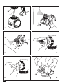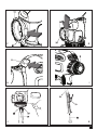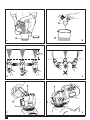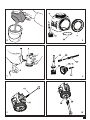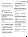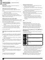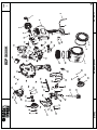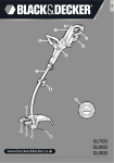
1
BDPS200
BDPS400
BDPS600
2
A
B1
B2
C
D
E
F
G
H
I
J
K
3
L
M
N
O
1
2
P
4
Q
R
S
T
U
V
W
5
X
Z
6
Y
(Original instructions)
Intended use
Your Black & Decker floor based fine spray system is
intended for atomising solvent based and water based paints,
finishes, primers, clear finishes, automotive finishes, staining
sealers, wood sealer-preservatives. The power tool is not
suitable for spraying caustic solutions, acidic coating
materials, coating materials with granules or solids as well as
spray and drip-impeding materials.. This appliance is intended
for consumer use only.
Safety instructions
General power tool safety warnings
@
Warning! Read all safety warnings and all
instructions. Failure to follow the warnings and
instructions listed below may result in electric
shock, fire and/or serious injury.
Save all warnings and instructions for future reference.
The term "power tool" in all of the warnings listed below refers
to your mains operated (corded) power tool or battery operated (cordless) power tool.
1. Work area safety
a. Keep work area clean and well lit. Cluttered or dark
areas invite accidents.
b. Do not operate power tools in explosive atmospheres,
such as in the presence of flammable liquids, gases
or dust. Power tools create sparks which may ignite the
dust or fumes.
c. Keep children and bystanders away while operating a
power tool. Distractions can cause you to lose control.
2. Electrical safety
a. Power tool plugs must match the outlet. Never modify
the plug in any way. Do not use any adapter plugs
with earthed (grounded) power tools. Unmodified plugs
and matching outlets will reduce risk of electric shock.
b. Avoid body contact with earthed or grounded
surfaces such as pipes, radiators, ranges and
refrigerators. There is an increased risk of electric shock
if your body is earthed or grounded.
c. Do not expose power tools to rain or wet conditions.
Water entering a power tool will increase the risk of
electric shock.
d. Do not abuse the cord. Never use the cord for
carrying, pulling or unplugging the power tool. Keep
cord away from heat, oil, sharp edges or moving
parts. Damaged or entangled cords increase the risk of
electric shock.
ENGLISH
e. When operating a power tool outdoors, use an
extension cord suitable for outdoor use. Use of a cord
suitable for outdoor use reduces the risk of electric shock.
f. If operating a power tool in a damp location is
unavoidable, use a residual current device (RCD)
protected supply. Use of an RCD reduces the risk of
electric shock.
3. Personal safety
a. Stay alert, watch what you are doing and use common
sense when operating a power tool. Do not use a
power tool while you are tired or under the influence
of drugs, alcohol or medication. A moment of inattention
while operating power tools may result in serious personal
injury.
b. Use personal protective equipment. Always wear eye
protection. Protective equipment such as dust mask,
non-skid safety shoes, hard hat, or hearing protection
used for appropriate conditions will reduce personal
injuries.
c. Prevent unintentional starting. Ensure the switch is in
the off-position before connecting to power source
and/or battery pack, picking up or carrying the tool.
Carrying power tools with your finger on the switch or
energising power tools that have the switch on invites
accidents.
d. Remove any adjusting key or wrench before turning
the power tool on. A wrench or a key left attached to a
rotating part of the power tool may result in personal injury.
e. Do not overreach. Keep proper footing and balance at
all times. This enables better control of the power tool in
unexpected situations.
f. Dress properly. Do not wear loose clothing or
jewellery. Keep your hair, clothing and gloves away
from moving parts. Loose clothes, jewellery or long hair
can be caught in moving parts.
g. If devices are provided for the connection of dust
extraction and collection facilities, ensure these are
connected and properly used. Use of dust collection can
reduce dust-related hazards.
4. Power tool use and care
a. Do not force the power tool. Use the correct power
tool for your application. The correct power tool will do
the job better and safer at the rate for which it was
designed.
b. Do not use the power tool if the switch does not turn it
on and off. Any power tool that cannot be controlled with
the switch is dangerous and must be repaired.
7
ENGLISH
(Original instructions)
c. Disconnect the plug from the power source and/or the
battery pack from the power tool before making any
adjustments, changing accessories, or storing power
tools. Such preventive safety measures reduce the risk of
starting the power tool accidentally.
d. Store idle power tools out of the reach of children and
do not allow persons unfamiliar with the power tool or
these instructions to operate the power tool. Power
tools are dangerous in the hands of untrained users.
e. Maintain power tools. Check for misalignment or
binding of moving parts, breakage of parts and any
other condition that may affect the power tools
operation. If damaged, have the power tool repaired
before use. Many accidents are caused by poorly
maintained power tools.
f. Keep cutting tools sharp and clean. Properly
maintained cutting tools with sharp cutting edges are less
likely to bind and are easier to control.
g. Use the power tool, accessories and tool bits etc. in
accordance with these instructions, taking into
account the working conditions and the work to be
performed. Use of the power tool for operations different
from those intended could result in a hazardous situation.
5. Service
a. Have your power tool serviced by a qualified repair
person using only identical replacement parts. This
will ensure that the safety of the power tool is maintained.
Additional safety instructions
Warning!
u Read all instructions and safety precautions for equipment
and spray material before operation any equipment.
u Comply with all appropriate local, state and national codes
governing ventilation, fire prevention and operation.
u Keep sprayer out of reach of children.
u Hearing protection is recommended for extended use.
u Use eye protection to keep particles out of eyes.
Hazardous vapours
Insecticides and other materials may be harmful if inhaled
causing severe nausea, fainting or poisoning.
a. Use a respirator or mask whenever there is a chance
that vapours may be inhaled. Read all instructions
with the spray material and mask to ensure that it will
provide the necessary protection against the
inhalation of harmful vapours.
Additional safety instructions for paint sprayers
Warning!
u Before any use, be sure anyone using this sprayer reads
and understands all safety instructions and other information contained in this manual.
8
Do not use caustic (alkali) self heating or corrosive (acid)
liquids in this sprayer as these can corrode metal parts or
weaken hose and seals.
u Do not use hot or boiling liquids in sprayer as this may
weaken tank and hose.
u Do not leave residue or spray material in the tank after
using sprayer.
u Do not smoke while spraying or spray where spark of
flame is present.
u Do thoroughly inspect both inside and outside of sprayer
before each use.
u Do empty, clean and drain both tank and hose after each
use according to directions.
u Do not use guns for spraying flammable materials.
u Do not spray any material where the hazard is not known.
u Use only non-flammable liquids.
u Do not clean guns with flammable materials.
u
Personal safety
a. Additional personal safety equipment such as
appropriate gloves and a respirator or mask must be
used when handling chemicals. Safety equipment used
for appropriate conditions will reduce personal injuries.
b. Do not spray yourself, any person or animal. Keep
hands and other body parts away from the discharge.
In case of skin injection, seek medical attention
immediately. The sprayed material may pierce the skin
and be injected to your body.
c. Do not treat injection as a simple cut. Spray is able to
inject toxins into the body and cause serious bodily injury.
In the event that injection occurs, seek medical attention
immediately.
d. Beware of any hazards presented by the material
being sprayed. Consult the markings on the container
or the information supplied by the manufacturer of the
material to be sprayed, including requirements for the
use of personal protective equipment. Manufacturer's
instructions must be followed to reduce the risk of fire and
personal injury, derived from toxins, carcinogens, etc.
Safety of others
This appliance is not intended for use by persons (including children) with reduced physical, sensory or mental
capabilities, or lack of experience and knowledge, unless
they have been given supervision or instruction concerning the use of the appliance by a person responsible for
their safety.
u Children should be supervised to ensure that they do not
play with the appliance.
u
(Original instructions)
Residual risks.
Additional residual risks may arise when using the tool which
may not be included in the enclosed safety warnings. These
risks can arise from misuse, prolonged use etc.
Even with the application of the relevant safety regulations
and the implementation of safety devices, certain residual
risks can not be avoided. These include:
u Injuries caused by touching any moving parts.
u Injuries caused by touching any hot parts.
u Injuries caused when changing any parts or accessories.
u Injuries caused by prolonged use of the appliance. When
using any appliance for prolonged periods ensure you
take regular breaks.
Vibration
The declared vibration emission values stated in the technical
data and the declaration of conformity have been measured
in accordance with a standard test method provided by
EN 60745 and may be used for comparing one tool with
another. The declared vibration emission value may also be
used in a preliminary assessment of exposure.
Warning! The vibration emission value during actual use of
the power tool can differ from the declared value depending
on the ways in which the tool is used. The vibration level may
increase above the level stated.
When assessing vibration exposure to determine safety
measures required by 2002/44/EC to protect persons regularly
using power tools in employment, an estimation of vibration
exposure should consider, the actual conditions of use and the
way the tool is used, including taking account of all parts of the
operating cycle such as the times when the tool is switched off
and when it is running idle in addition to the trigger time.
Labels on the appliance
The following pictograms are shown on the tool:
:
R
O
Warning! To reduce the risk of injury, the user
must read the instruction manual.
Warning! Do not expose the appliance to rain or
high humidity.
Warning! Keep bystanders away.
6
&
ENGLISH
Warning! Wear a respirator or mask.
Warning! Use only non-flammable liquids.
Electrical safety
@
Warning! This product must be earthed.
Always check that the power supply corresponds to the voltage on the rating plate.
Power plugs must match the outlet. Never modify the plug in
any way. Unmodified plugs and matching outlets will reduce
risk of electric shock.
u If the supply cord is damaged, it must be replaced by
the manufacturer or an authorised Black & Decker
Service Centre in order to avoid a hazard.
Extension cables & Class 1 product
A 3-core cable must be used as your appliance is
earthed and of Class 1 construction.
u Up to 30m (100 ft) can be used without loss of power.
u Electric safety can be further improved by using a highsensitivity 30 mA residual current device (RCD).
u
Features
This appliance includes some or all of the following features.
1. Quick clean lever
2. Spray trigger
3. Sprayer
4. Power unit
5. Quick clean door
6. Side fill canister
7. Lid
8. Flow control knob
9. Speed control switch
10. Green fan spray nozzle (BDPS400 & BDPS600 only)
11. Blue cone nozzle
12. Mixing bucket (BDPS600 only)
13. Viscosity cup
14. Cleaning bush
15. Sprayer release button
16. Quick clean fill cup (BDSP600 only)
17. Paint can clip (BDSP600 only)
18. Direct to tin hose (BDSP600 only)
Warning! Wear safety glasses or goggles when
operating this tool.
9
ENGLISH
(Original instructions)
Assembly
Warning! Before assembly, make sure that the tool is
switched off and unplugged.
Attaching the side fill canister (fig. A)
The side fill canister is designed so it will only fit one way
round.
u Align the side fill canister (6) below the pick up tube (19)
with the lid (7) to the left.
u Push the side fill canister (6) firmly into place.
u Tighten the locking ring (20) by turning it clockwise.
Note: Ensure that the locking ring is tight and that the side fill
canister is firmly secured in place.
Aligning the pickup tube (fig. B1 & B2)
The pickup tube can be aligned in the direction that you will be
doing the most spraying to help minimize the amount of times
that you will have to refill the canister.
u If you are spraying at an upward angle or straight on,
position the pickup tube (fig. B) toward the back of the
canister.
u If you are spraying at a downward angle, position the
pickup tube (fig. C) toward the front of the canister.
This will ensure you spray as much material as possible
before you need to refill.
Attaching and removing the spray nozzels (fig. C
& D)
To attach the green fan spray nozzle: (Where supplied)
u Turn the nozzle (10) clockwise onto the spindle for 6 - 8
full turns.
u Push in the nozzle (10) and continue to turn it clockwise
untill it is fully seated.
Note: Ensure the spray nozzle is completely threaded on by
hand only. If it is not fully seated in can leak or damage the
nozzle.
Filling the canister (fig. E
Check to make sure that the side fill canister (6) is completely screwed onto the sprayer.
u Lay the sprayer on its side with the canister side lid facing
up.
u Pour the properly thinned and strained material to be
sprayed into the side fill canister.
Note : Use a mixing bucket to pour material from the original
material container into the side fill canister.
u Clean any residual liquid from the threads or sides of the
canister and sprayer.
u Starting the threads evenly, screw the lid completely
onto the side fill canister. Check the lid to make sure it is
threaded on squarely and completely before picking up
the sprayer.
u
Use
Switching on and off
The sprayer is turned on and off with the spray trigger.
u To turn the sprayer on, squeeze the spray trigger (2).
u To turn the sprayer off, release the spray trigger (2).
Warning! Never point the sprayer at any part of the body.
Never pull the trigger while adjusting the spray setting.
Selecting the spray pattern (fig. F & G) (BDPS400 &
BDPS600 Only
This sprayer is supplied with 2 nozzles which are capable of
producing 3 spray patterns. .
Green nozzle - Horizontal Flat Jet - Apply up and down
a surface.
Green nozzle - Vertical Flat Jet - Apply side to side.
Blue nozzle - Circular Jet - for corners, edges and narrow
surfaces.
To remove the green fan spray nozzle: (Where supplied)
u Push in the nozzle (10) and turn it anticlockwise.
To attach the blue cone spray nozzle:
u Turn the nozzle (11) clockwise onto the spindle until it is
fully seated.
Note: Ensure the spray nozzle is completely threaded on by
hand only. If it is not fully seated in can leak or damage the
nozzle.
To remove the blue cone spray nozzle:
u Turn the nozzle (11) anticlockwise.
10
To select the cone spray pattern, fit the blue cone nozzle.
To select the horizontal fan spray pattern, fit the green fan
spray nozzle and turn the nozzle so so the jet indicator
tabs (21) are in the vertical position (fig. F).
u To select the Vertical fan spray pattern, fit the green fan
spray nozzle and turn the nozzle so so the jet indicator
tabs (21) are in the horizontal position (fig. G).
Warning! Never point the sprayer at any part of the body.
Never pull the trigger while adjusting the spray setting.
u
u
(Original instructions)
Two speed control switch (fig. H) (BDPS600 only)
Your sprayer has two different speed settings.
u To change speeds, press the speed control switch (9). An
LED indicates setting 1 or 2.
u Set the flow control knob (8) to a lower or medium settting
(1-5) when on speed setting 1.
u Set the flow control knob (8) to medium or higher setting
(5-9) when on speed setting 2.
Use the lower speed setting (Setting 1) to obtain greater control over your spraying project, while the higher speed (Setting
2) allows for greater coverage in a shorter amount of time.
The lower speed level allows you to get closer to your work
with less overspray. Low setting works well with lighter bodied
or more free flowing paints like stains and sealers.
More heavy bodied paints, like water based latex, will need
setting number 2
Use the speed control setting in conjuction with the flow
control knob and test for what works best with your material
being sprayed.
Flow control knob (fig. I)
The flow control knob regulates the amount of liquid that can
be sprayed.
u Turn the flow control knob (8) clockwise to increase the
flow of liquid
u Turn the flow control knob (8) counterclockwise to
decrease the flow of liquid.
Note : Always test the spray pattern on scrap cardboard
or similar material first. Begin with flow control knob on the
highest flow setting. If less flow is desired, dial the flow control
knob in. Heavier, thicker materials should be sprayed with the
higher settings 7 - 9. Thinner materials should be sprayed with
the lower settings 1 -3.
Note : If the flow control setting is set completely to the
minimum side, the trigger will have limited or no travel. Back
the flow control knob off (clockwise) to allow for more trigger
travel.
Direct to tin hose (fig. J & K) (BDPS600 only)
It is possible to use the BDPS600 with out the side fill canister.
When using the supplied 'direct to tin hose' you can take the
paint supply directly from the paint tin.
u Remove the sidefill canister (6), pickup tube (19) and filter
(25).
u Push the suction hose onto the intake (30) and return (29)
ports.
u Pull the hose apart on the opposite end and slide the
larger hose (17) completely through the container clip
(18), then over the barbs (22) of the pickup tube (19).
u Place the suction tube assembly into the material container and attach the container clip securely to the side.
Check to make sure that complete assembly is submerged
in the material container.
ENGLISH
Liquid material preparation (fig. L & M)
Note : Make sure the type of material you use can be cleaned
with either mineral spirits or paint thinner (for oil-based paints)
or a warm water and soap solution (for water soluble paints
like latex). Use drop cloths to protect your floors and anything
else in the spraying area that you wish to remain untouched.
The liquid being sprayed may need to be thinned (diluted)
before staring. When thinning, use the proper liquid thinner
recommended on the container by the material manufacturer.
Warning! Do not use materials with a flashpoint lower than
55°C.
Note : A mixing bucket (12) is provided (BDPS600 only)to use
when transferring spray material from the original container
into the bucket for thinning and measuring purposes (fig. L).
Note : A viscosity cup (13) is provided to determine the
“runout time” of the material being used.
u Before measuring for the proper viscosity, stir the material
thoroughly.
u Dip the viscosity cup (13) into the material being sprayed
and fill the viscosity cup (13) completely.
u With the viscosity cup (13) held over the material container, measure the amount of time it takes for the stream
of material flowing out to “break” or stop being a constant
stream out of the bottom of the viscosity cup (13) (2
minutes or less) (fig. M). This is the “runout time” Refer to
the thinning table for information on the thinning required
for different materials.
u If material needs thinning, add the appropriate liquid thinning material recommended by the manufacturer.
u It is possible to spray latex paint with this unit, however
the paint may require thinning. In some cases the paint
may require thinning beyond the paint manufacturers
recommendations, please consult the paint manufacturers
instructions. If a paint is found to be too thick and will not
spray, thin the paint using the appropriate thinning material. Thinning material should be added at a ratio of 5% of
the volume of paint until the paint flows through the paint
gun providing an even and satisfactory finish.
Thinning table
Spray material
Clear and semi-transparent stains
and sealers
Oil based primers, varnishes and
polyurethane
Runout time
No thinning required
(Less than 2 minute runout)
Solid colour water based stains
May require thinning
Water based or latex paints
(More than 2 minute runout)
Note : Not recommended for textured paint
11
ENGLISH
(Original instructions)
Hints for optimum use
Preparation tips
u Always stir and strain the material thoroughly before use.
u With any spraying job you should always ensure that
you have properly prepared the surface to get the best
finish. That is, all surfaces are free from dust, dirt, rust and
grease. Lightly pressure wash decks or exterior surfaces
and ensure that they are dry before spraying.
u It is recommended that you mask all edges and other
areas and use drop cloths to protect your floors and
anything else in the spraying area that you wish to remain
untouched.
u Skin that forms on the top of paint can clog the sprayer.
Remove skin before mixing. Strain with a funnel with a
filter attached or through hosiery to remove any impurities
that could clog system.
u Before starting have gloves, paper towels, rags etc. available for unexpected spills.
Developing the proper spraying technique (fig. N & O)
u Practice spraying on a piece of scrap material such as
cardboard to test your spray pattern and become familiar
with the flow control feature of the sprayer.
u Ensure surface to be sprayed is free of dust, dirt, and
grease.
u Ensure spray area is clean and free of dust that could be
blown onto newly sprayed surfaces.
u Cover any areas not intended to be sprayed.
u Always spray from a minimum of 25mm to a maximum of
355mm (fig. N).
u A commonly used method for spraying a large surface
is the “crisscross” pattern. This is done by spraying in
horizontal strips and then crossing over these strips with
vertical strips.
u To get an even spray distribution, always keep your arm at
the same distance (fig. N) from the surface you are spraying and avoid moving your wrist (fig. O).
u Maintain smooth and consistent speed which will help
avoid inconsistencies. Begin spraying after the pass has
begun and release trigger before stopping the pass.
u Avoid spraying too heavily in any one area. Several lighter
coats are better than one heavy coat which can lead to
running and dripping. Remember that the flow control
knob regulates the amount of liquid that can be sprayed.
Turning the flow knob clockwise increases the flow of
liquid. Turning the knob counterclockwise decreases the
flow of liquid. If runs or drips do occur, have a dry paint
brush on hand to smooth them out.
u Turn the power unit off and place the sprayer in the built-in
dock of the power unit when not spraying for any length of
time.
12
Maintenance and cleaning
Your Black & Decker corded appliance has been designed to
operate over a long period of time with a minimum of maintenance. Continuous satisfactory operation depends upon
proper appliance care and regular cleaning.
Warning! Be sure to use appropriate personal protective
equipment.
Warning! Before performing any maintenance or cleaning on
corded appliances switch off and unplug the appliance.
Warning! Do not use materials with a flashpoint lower than
55°C. Flashpoint is the temperature that a fluid can produce
enough vapours to ignite (see paint supplier instructions).
Warning! Make sure clean up area is well ventilated and free
of flammable vapours.
Warning! Always spray outdoors when spraying cleaning
solution through sprayer.
Warning! Do not submerse power unit.
Using the quick clean system (fig. P & Q) (BDPS400
& BDPS600 only)
The quick clean system allows for a variety of useful functions.
First, the system can allow you to spray water or a suitable
cleaning liquid while there is still spray material in the main
canister. This is useful when setting up your spray pattern with
the fan nozzle. You can spray water instead of wasting spray
material to view the spray pattern.
Second, the quick clean system allows you to flush the pump
assembly, the piston, the nozzle and the atomizer valve. When
spraying for long periods of time, spray material may build
up causing a deterioration of the spray quality. It is good to
flush this system with water or cleaning liquid after every other
spray material refill. It is also important to flush the system
when the sprayer will sit for more than 15 minutes without use.
Spray material can dry on the nozzle and pump assembly and
would require a thorough cleaning. Always oil piston if sitting
idle for a long period of time. See “Reassembly Section”.
Third, the quick clean system allows for a faster clean-up
when your project is complete. One or two flushes through
the quick clean system gives you a head start on cleaning
the nozzle, the atomizer, the pump and piston. Please follow
recommended cleaning steps in this manual when performing
a final clean of the system.
u Disconnect the sprayer from the power supply.
u Open the quick clean door (5), and pour in the cleaning
solution using the quick clean fill cup (16).
Warning! Do not overfill the reservoir.
u Switch the quick clean lever (1) from paint to clean.
u Spray into a waste container, cardboard box or test
surface to completely flush the sprayer system.
u Repeat until the cleaning solution has returned to its
natural colour.
(Original instructions)
Flushing the sprayer (fig. Q & R)
u Disconnect the sprayer from the power supply.
u Unscrew the lid from the side of the canister and pour any
remaining liquid back into the original container (fig. R).
u Pour a small amount of the appropriate cleaning solution
into the canister.
t Warm soapy water for water based materials.
t Manufacturers recommended cleaning solution for oil
based materials.
u Replace the lid (7) on the canister (6) securely and vigorously shake the sprayer.
u Unscrew the lid (7) from the side of the canister and
properly dispose of cleaning solution.
u Refill the canister with a small amount of new cleaning
solution. Screw lid securely on canister.
u Reattach the sprayer to the motor unit, plug in the cord
and turn on the power unit.
u Switch the quick clean lever (1) from clean to paint. (fig.Q)
u Spray the cleaning solution through the sprayer onto scrap
material for 5 seconds.
Cleaning the sprayer (fig. S - X)
u Disconnect the sprayer from the power supply.
u Remove the side fill canister (6) and unscrew the side lid
(7). Remove the pickup tube (19) and o-ring (23) from the
sprayer. Clean the parts with the cleaning brush (14) in the
appropriate cleaning solution (fig. S).
u Remove the front housing of the sprayer, by pressing
down on the release button (15) and pulling the front
housing off of the sprayer (fig. T).
u Remove the piston (27) and spring (26) (fig. U).
u Remove the spray nozzle (10 / 11), by turning counterclockwise, then remove the atomizer (24) (fig. U).
u Clean the spray nozzle (10 / 11), pickup tube (19) and filter
(25), atomizer (24), piston (27) and spring (26) with the
cleaning brush (14) in the appropriate cleaning solution
(fig. T).
u Thoroughly clean the inside of the piston chamber (28)
with the cleaning brush (14) (fig. V)
Important : Be sure to remove all material from inside
of piston chamber. A small amount of material that is not
removed with the cleaning brush can harden over time and
interfere with the movement of the piston causing damage to
the sprayer.
u Switch the quick clean lever (1) from clean to paint.
u Thoroughly clean the inside of the intake (30) and return
(29) openings with the cleaning brush (fig. W).
Important : Thoroughly clean the smaller vent hole (31), with
a pin or paper clip (fig. X).
u Dry all parts thoroughly.
u Properly dispose of cleaning solution.
u Reassemble sprayer.
ENGLISH
Reassembling the sprayer (fig. Y & Z)
u Slide the spring (26) onto the front of the piston (27).
u Insert the piston and spring into the front housing.
u Pressing down on the release button (15), insert the front
housing with piston, into the sprayer until the release button pops into place.
u Place a few drops of oil through the cylinder opening. Insert the atomizer valve (24) into the front housing. Thread
the spray nozzle (10 / 11) onto the front housing and hand
tighten.
u Using the oil lubricant provided, place a few drops of
oil down the intake (30) and return (29) openings of the
sprayer.
u Rotate the quick clean lever (1) from paint to clean and
back 3 times after oiling.
u Insert the pickup tube (19) into the intake opening (30) on
the sprayer.
u Re-fit the side fill canister.
Cleaning the power unit
u Turn the power unit off, unplug the cord and disconnect
the sprayer from the motor unit.
u Use only mild soap and damp cloth to clean the power
unit.
Warning! Never let any liquid get inside the power unit.
Warning! Never immerse any part of the power unit into a
liquid.
Mains plug replacement (U.K. & Ireland only)
If a new mains plug needs to be fitted:
u Safely dispose of the old plug.
u Connect the brown lead to the live terminal in the new
plug.
u Connect the blue lead to the neutral terminal.
u Connect the green/yellow lead to the earth terminal.
Warning! Follow the fitting instructions supplied with good
quality plugs. Recommended fuse: 13A.
Protecting the environment
Z
Separate collection. This product must not be
disposed of with normal household waste.
Should you find one day that your Black & Decker product
needs replacement, or if it is of no further use to you, do not
dispose of it with household waste. Make this product available for separate collection.
z
Separate collection of used products and packaging
allows materials to be recycled and used again.
Re-use of recycled materials helps prevent environmental pollution and reduces the demand for raw
materials.
13
(Original instructions)
ENGLISH
EC declaration of conformity
Local regulations may provide for separate collection of electrical products from the household, at municipal waste sites or
by the retailer when you purchase a new product.
Black & Decker provides a facility for the collection and
recycling of Black & Decker products once they have reached
the end of their working life. To take advantage of this service
please return your product to any authorised repair agent who
will collect them on our behalf.
You can check the location of your nearest authorised repair
agent by contacting your local Black & Decker office at
the address indicated in this manual. Alternatively, a list of
authorised Black & Decker repair agents and full details of our
after-sales service and contacts are available on the Internet
at: www.2helpU.com
Technical data
Voltage
Vac
Power
W
Tank capacity
l
Weight
kg
BDPS200
BDPS400
BDPS600
(Type 1)
(Type 1)
(Type 1)
230
230
230
120
150
150
1.2
1.2
1.2
2.1
2.2
2.2
Level of sound pressure according to EN 60745:
Sound pressure (LpA) 90 dB(A), uncertainty (K) 3 dB(A)
Sound power (LWA) 103 dB(A), uncertainty (K) 3 dB(A)
Vibration total values (triax vector sum) according to EN 60745:
Vibration emission value (ah, D) 11 m/s2, uncertainty (K) 1.5 m/s2
14
%
MACHINERY DIRECTIVE
BDPS200, BDPS400, BDPS600
Black & Decker declares that these products described under
"technical data" are in compliance with:
2006/42/EC, EN60745
For more information, please contact Black & Decker at the
following address or refer to the back of the manual.
The undersigned is responsible for compilation of the technical
file and makes this declaration on behalf of Black & Decker.
_
Kevin Hewitt
Vice-President Global Engineering
Black & Decker Europe, 210 Bath Road, Slough,
Berkshire, SL1 3YD
United Kingdom
28/09/2011
Guarantee
Black & Decker is confident of the quality of its products and
offers an outstanding guarantee. This guarantee statement is
in addition to and in no way prejudices your statutory rights.
The guarantee is valid within the territories of the Member
States of the European Union and the European Free Trade
Area.
If a Black & Decker product becomes defective due to faulty
materials, workmanship or lack of conformity, within 24
months from the date of purchase, Black & Decker guarantees
to replace defective parts, repair products subjected to fair
wear and tear or replace such products to ensure minimum
inconvenience to the customer unless:
u The product has been used for trade, professional or hire
purposes;
u The product has been subjected to misuse or neglect;
u The product has sustained damage through foreign
objects, substances or accidents;
u Repairs have been attempted by persons other than
authorised repair agents or Black & Decker service staff.
To claim on the guarantee, you will need to submit proof of
purchase to the seller or an authorised repair agent. You can
check the location of your nearest authorised repair agent
by contacting your local Black & Decker office at the address
indicated in this manual. Alternatively, a list of authorised
Black & Decker repair agents and full details of our aftersales service and contacts are available on the Internet at:
www.2helpU.com
Please visit our website www.blackanddecker.co.uk to register
your new Black & Decker product and to be kept up to date
on new products and special offers. Further information on the
Black & Decker brand and our range of products is available
at www.blackanddecker.co.uk
15
25
E16491
33
65
32
31
63
30
61
60
35
20
64
1
39
63
62
45
2
40
www.2helpU.com
38
41
18
17
16
15
44
47
46
43
48
13 12
42
14
BDPS200
3
11
10
5
9
8
6
62
7
09 - 09 - 11
TYP.
1
37
75
E16492
70
45
43
46
71
44
73
27
28
42
26
50
48
51
74
52
25
53
73
24
20
57
21
www.2helpU.com
55
72
15
22
19
17
BDPS400
16
18
62
60
58
13
1
59
56
12
14
2
61
11
63
3
10
9
4
72
7
09 - 09 - 11
5
8
TYP.
1
38
E16482
39
37
40 41
36 35
34
28
43
42
33
27
46
32
26
45
44
52
48
29
51
47
50
31
30
25
69
67
54
53
49
24
1
63
61
15
22
21
www.2helpU.com
68
66
55
23
20
18
13
11
3
62
64
59
57
12
60
58
14
2
56
17 16
19
BDPS600K
10
65
9
8
5
4
09 - 09 - 11
6
7
1
TYP
ENGLISH
Do not forget to register your product!
www.blackanddecker.co.uk/productregistration
Register your product online at www.blackanddecker.co.uk/productregistration or send your name, surname and product
code to Black & Decker in your country.
Australia
Black & Decker (Australia) Pty. Ltd.
20 Fletcher Road, Mooroolbark, Victoria, 3138
New Zealand
Black & Decker
5 Te Apunga Place
Mt Wellington
Auckland 1060
United Kingdom
Black & Decker
210 Bath Road
Slough, Berkshire SL1 3YD
90580717 REV-0
Tel. 03-8720 5100
Fax 03-9727 5940
Tel. +64 9 259 1133
Fax +64 9 259 1122
Tel. 01753 511234
Fax 01753 551155
09/2011