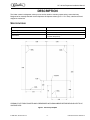
1
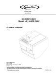
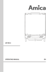
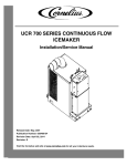
MODEL: UC 150 ICE DISPENSER
Installation Manual
Revision Date: August, 1999
Publication Number: 620917312
Revision Date: August 3, 2010
Revision: C
Visit the IMI Cornelius web site at www.cornelius.com for all your Literature needs.
The products, technical information, and instructions contained in this manual are subject to change without notice.
These instructions are not intended to cover all details or variations of the equipment, nor to provide for every possible contingency in the installation, operation or maintenance of this equipment. This manual assumes that the person(s) working on the equipment have been trained and are skilled in working with electrical, plumbing, pneumatic,
and mechanical equipment. It is assumed that appropriate safety precautions are taken and that all local safety and
construction requirements are being met, in addition to the information contained in this manual.
This Product is warranted only as provided in Cornelius’ Commercial Warrant applicable to this Product and is subject to all of the restrictions and limitations contained in the Commercial Warranty.
Cornelius will not be responsible for any repair, replacement or other service required by or loss or damage resulting
from any of the following occurrences, including but not limited to, (1) other than normal and proper use and normal
service conditions with respect to the Product, (2) improper voltage, (3) inadequate wiring, (4) abuse, (5) accident,
(6) alteration, (7) misuse, (8) neglect, (9) unauthorized repair or the failure to utilize suitably qualified and trained persons to perform service and/or repair of the Product, (10) improper cleaning, (11) failure to follow installation, operating, cleaning or maintenance instructions, (12) use of “non-authorized” parts (i.e., parts that are not 100%
compatible with the Product) which use voids the entire warranty, (13) Product parts in contact with water or the
product dispensed which are adversely impacted by changes in liquid scale or chemical composition.
Contact Information:
To inquire about current revisions of this and other documentation or for assistance with any Cornelius product contact:
www.cornelius.com
800-238-3600
Trademarks and Copyrights:
This document contains proprietary information and it may not be reproduced in any way without permission from
Cornelius.
Printed in U.S.A.
TABLE OF CONTENTS
Safety Instructions. . . . . . . . . . . . . . . . . . . . . . . . . . . . . . . . . . . . . . . . . . . . . . . . . . . . . . . . . . . . . . . . . 1
Read and Follow ALL Safety Instructions . . . . . . . . . . . . . . . . . . . . . . . . . . . . . . . . . . . . . . . . . . . . . 1
Safety Overview . . . . . . . . . . . . . . . . . . . . . . . . . . . . . . . . . . . . . . . . . . . . . . . . . . . . . . . . . . . . . . 1
Recognition . . . . . . . . . . . . . . . . . . . . . . . . . . . . . . . . . . . . . . . . . . . . . . . . . . . . . . . . . . . . . . . . . 1
Different Types of Alerts . . . . . . . . . . . . . . . . . . . . . . . . . . . . . . . . . . . . . . . . . . . . . . . . . . . . . . . . . . 1
Safety Tips . . . . . . . . . . . . . . . . . . . . . . . . . . . . . . . . . . . . . . . . . . . . . . . . . . . . . . . . . . . . . . . . . . . . . 1
Qualified Service Personnel. . . . . . . . . . . . . . . . . . . . . . . . . . . . . . . . . . . . . . . . . . . . . . . . . . . . . . . . 1
Safety Precautions. . . . . . . . . . . . . . . . . . . . . . . . . . . . . . . . . . . . . . . . . . . . . . . . . . . . . . . . . . . . . . . 2
Shipping And Storage . . . . . . . . . . . . . . . . . . . . . . . . . . . . . . . . . . . . . . . . . . . . . . . . . . . . . . . . . . . . 2
CO2 (Carbon Dioxide) Warning . . . . . . . . . . . . . . . . . . . . . . . . . . . . . . . . . . . . . . . . . . . . . . . . . . . . . 2
Mounting in or on a Counter . . . . . . . . . . . . . . . . . . . . . . . . . . . . . . . . . . . . . . . . . . . . . . . . . . . . . . . 2
Description . . . . . . . . . . . . . . . . . . . . . . . . . . . . . . . . . . . . . . . . . . . . . . . . . . . . . . . . . . . . . . . . . . . . . . . 3
Specifications. . . . . . . . . . . . . . . . . . . . . . . . . . . . . . . . . . . . . . . . . . . . . . . . . . . . . . . . . . . . . . . . . . . 3
Installation Instructions . . . . . . . . . . . . . . . . . . . . . . . . . . . . . . . . . . . . . . . . . . . . . . . . . . . . . . . . . . . . 5
Torsion Bar Removal . . . . . . . . . . . . . . . . . . . . . . . . . . . . . . . . . . . . . . . . . . . . . . . . . . . . . . . . . . . . . 5
UC 150 Ice Dispenser Installation Manual
SAFETY INSTRUCTIONS
READ AND FOLLOW ALL SAFETY INSTRUCTIONS
Safety Overview
•
Read and follow ALL SAFETY INSTRUCTIONS in this manual and any warning/caution labels on the unit (decals, labels or
laminated cards).
•
Read and understand ALL applicable OSHA (Occupational Safety and Health Administration) safety regulations before
operating this unit.
Recognition
Recognize Safety Alerts
!
This is the safety alert symbol. When you see it in this manual or on the unit,
be alert to the potential of personal injury or damage to the unit.
DIFFERENT TYPES OF ALERTS
! DANGER:
Indicates an immediate hazardous situation which if not avoided WILL result in serious injury, death or equipment
damage.
! WARNING:
Indicates a potentially hazardous situation which, if not avoided, COULD result in serious injury, death, or equipment
damage.
! CAUTION:
Indicates a potentially hazardous situation which, if not avoided, MAY result in minor or moderate injury or equipment
damage.
SAFETY TIPS
•
Carefully read and follow all safety messages in this manual and safety signs on the unit.
•
Keep safety signs in good condition and replace missing or damaged items.
•
Learn how to operate the unit and how to use the controls properly.
•
Do not let anyone operate the unit without proper training. This appliance is not intended for use by very young children or
infirm persons without supervision. Young children should be supervised to ensure that they do not play with the appliance.
•
Keep your unit in proper working condition and do not allow unauthorized modifications to the unit.
QUALIFIED SERVICE PERSONNEL
! WARNING:
Only trained and certified electrical, plumbing and refrigeration technicians should service this unit. ALL WIRING AND
PLUMBING MUST CONFORM TO NATIONAL AND LOCAL CODES. FAILURE TO COMPLY COULD RESULT IN
SERIOUS INJURY, DEATH OR EQUIPMENT DAMAGE.
© 1999-2010, IMI Cornelius Inc.
-1-
Publication Number: 620917312
UC150 Ice Dispenser Installation Manual
SAFETY PRECAUTIONS
This unit has been specifically designed to provide protection against personal injury. To ensure continued protection
observe the following:
! WARNING:
Disconnect power to the unit before servicing following all lock out/tag out procedures established by the user. Verify
all of the power is off to the unit before any work is performed.
Failure to disconnect the power could result in serious injury, death or equipment damage.
! CAUTION:
Always be sure to keep area around the unit clean and free of clutter. Failure to keep this area clean may result in
injury or equipment damage.
SHIPPING AND STORAGE
! CAUTION:
Before shipping, storing, or relocating the unit, the unit must be sanitized and all sanitizing solution must be drained
from the system. A freezing ambient environment will cause residual sanitizing solution or water remaining inside the
unit to freeze resulting in damage to internal components.
CO2 (CARBON DIOXIDE) WARNING
! DANGER:
CO2 displaces oxygen. Strict attention MUST be observed in the prevention of CO2 gas leaks in the entire CO2 and
soft drink system. If a CO2 gas leak is suspected, particularly in a small area, IMMEDIATELY ventilate the
contaminated area before attempting to repair the leak. Personnel exposed to high concentrations of CO2 gas
experience tremors which are followed rapidly by loss of consciousness and DEATH.
MOUNTING IN OR ON A COUNTER
! WARNING:
When installing the unit in or on a counter top, the counter must be able to support a weight in excess of 350 lbs. to
insure adequate support for the unit. FAILURE TO COMPLY COULD RESULT IN SERIOUS INJURY, DEATH OR
EQUIPMENT DAMAGE.
NOTE: Many units incorporate the use of additional equipment such as ice makers. When any addition
equipment is used you must check with the equipment manufacturer to determine the
additional weight the counter will need to support to ensure a safe installation.
Publication Number: 620917312
-2-
© 1999-2010, IMI Cornelius Inc.
UC 150 Ice Dispenser Installation Manual
DESCRIPTION
The Under counter ice dispenser solves your ice service needs in a sanitary, space saving, economical way.
Designed to be manually filled with ice this dispenser will dispense cubes (up to 1-1/4” in size), cube lets and hard
chipped or cracked ice.
SPECIFICATIONS
Model:
UC150
Ice Storage:
150lbs
Electrical:
120/1/60, 3 amps total unit draw
Dimensions:
30” wide X 33-5/8” Deep X 27” Below Counter 16-9/16” Above
Counter Respectively
CORIAN IS CUT FROM COUNTER AND IS REWORKED AS SHOWN ABOVE BEFORE BEING GLUED TO UC
150 DOOR LIDS
Figure 1. Corian Top Template
© 1999-2010, IMI Cornelius Inc.
-3-
Publication Number: 620917312
UC150 Ice Dispenser Installation Manual
THE ABOVE FIGURE SHOWS THE REQUIRED CUTOUT FOR PLACING THE ICE DISPENSERINTO A
COUNTER TOP. THE DOTTED LINE IS THE ACTUAL CUTOUT DIMENSIONS WHILE THE SOLID LINE SHOWS
THE AMOUNT OF OVERHANG FOR THE DISPENSER.
Figure 2. Counter Cutout Dimensions Template
Publication Number: 620917312
-4-
© 1999-2010, IMI Cornelius Inc.
UC 150 Ice Dispenser Installation Manual
INSTALLATION INSTRUCTIONS
! WARNING:
It is the responsibility of the installer to ensure that the water supply to the dispensing equipment is provided with
protection against backflow by an air gap as defined in ANSI/ASME A112. 1.2-1976; or an approved vacuum breaker
or other such method as proved effective by test and must comply with all federal, state and local codes.
Failure to comply could result in serious injury, death or damage to the equipment.
Water pipe connections and fixtures directly connected to a potable water supply shall be sized, installed, and
maintained according to federal, state and local laws.
1. Locate the dispenser indoors on a level counter top.
A. COUNTER MOUNTING
The ice dispenser must be sealed to the counter. The template drawing indicates the opening that must be
cut in the counter. Locate the desired position for the dispenser, then mark the outline dimensions on the
counter using the template drawings. Cut openings in counter.
Apply a continuous bead of NSF International (NSF) listed silastic sealant (Dow 732 or equal) approximately
1/4” inside of the unit outline dimensions and around all openings. Then, position the unit on the counter
within the outline dimensions. All excess sealant must be wiped away immediately.
2. HOPPER DRAIN ASSEMBLY
A. Clean the hopper interior (see CLEANING INSTRUCTIONS in Operator’s Manual).
B. Connect the power cord to a 120 volt, 60 cycle, 15-Amp, 3--wire grounded receptacle.
3. The drain tubes are routed through the large opening in the bottom of the unit. The power cord is routed
through the holes in either side of the unit.
A. Use 3/4” nominal plastic pipe.
B. To assure proper drainage, do not allow “trap” to form in drain line. Be sure drain line runs with a pitch
of 1” per foot.
4. SINK DRAIN ASSEMBLY: Connect the drain tube to an open drain. The drain tube must continuously pitch
downward and contain no “traps” or improper drainage will result.
TORSION BAR REMOVAL
The hinged door as shipped from the factory is set up for the mounting of Corian on the top. If Corian not used, it is
recommended that the rear torsion bar be removed to decrease the spring force.
To accomplish this task, perform the following procedure:
1.
Remove (Balloon Item 46) Ice Deflector by removing the three knurled screws that hold the Ice Deflector in place.
2. Break the RTV seal that holds the polymeric inner lid in place. This should be done with a sharp instrument.
3. Gently pry the inner lid out of the stainless steel cover.
4. Now that the complete Torsion Bar Assembly is visible, locate the Counter Balance Pivot which is balloon
Item 71. Using an 11/32” socket or equivalent, remove the two 8-32 hex nuts.
5. Carefully pry the pivot up and away from the mounting studs. As you do this, the torsion shafts will move
along with the pivot.
6. Once the pivot is free of the studs, moving it a little further towards you should allow the torsion shafts to
come free of the pivot.
7. You should be able to grab the rear torsion bar at this time and pull away from the end that is captured in the
sheet metal bracket.
8. Reverse the steps to reassemble the door.
9. RTV liner back in place.
© 1999-2010, IMI Cornelius Inc.
-5-
Publication Number: 620917312
UC150 Ice Dispenser Installation Manual
Figure 3. Torsion Bar Removal
Publication Number: 620917312
-6-
© 1999-2010, IMI Cornelius Inc.
UC 150 Ice Dispenser Installation Manual
Figure 4. Wiring Diagram
© 1999-2010, IMI Cornelius Inc.
-7-
Publication Number: 620917312
UC150 Ice Dispenser Installation Manual
Figure 5. Agitator Motor and Dispense Switch Wiring Detail
Publication Number: 620917312
-8-
© 1999-2010, IMI Cornelius Inc.
UC 150 Ice Dispenser Installation Manual
Figure 6. UC 150 Plumbing
© 1999-2010, IMI Cornelius Inc.
-9-
Publication Number: 620917312
UC150 Ice Dispenser Installation Manual
Publication Number: 620917312
- 10 -
© 1999-2010, IMI Cornelius Inc.
IMI Cornelius Inc.
www.cornelius.com