1
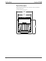
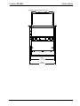
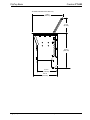
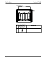
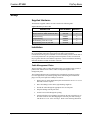
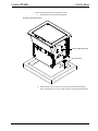
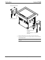
Crestron FT-600
FlipTop™ Basic
Operations & Installation Guide
Regulatory Compliance
This product is Listed to applicable UL Standards and requirements by Underwriters Laboratories Inc.
As of the date of manufacture, the FT-600 has been tested and found to comply with specifications for CE
marking.
Federal Communications Commission (FCC) Compliance Statement
This device complies with part 15 of the FCC Rules. Operation is subject to the following conditions:
(1) This device may not cause harmful interference and (2) this device must accept any interference received,
including interference that may cause undesired operation.
CAUTION: Changes or modifications not expressly approved by the manufacturer responsible for
compliance could void the user’s authority to operate the equipment.
NOTE: This equipment has been tested and found to comply with the limits for a Class B digital device,
pursuant to part 15 of the FCC Rules. These limits are designed to provide reasonable protection against
harmful interference in a residential installation. This equipment generates, uses and can radiate radio
frequency energy and, if not installed and used in accordance with the instructions, may cause harmful
interference to radio communications. However, there is no guarantee that interference will not occur in a
particular installation. If this equipment does cause harmful interference to radio or television reception,
which can be determined by turning the equipment off and on, the user is encouraged to try to correct the
interference by one or more of the following measures:
•
Reorient or relocate the receiving antenna
•
Increase the separation between the equipment and receiver
•
Connect the equipment into an outlet on a circuit different from that to which the receiver is connected
•
Consult the dealer or an experienced radio/TV technician for help
Industry Canada (IC) Compliance Statement
CAN ICES-3(B)/NMB-3(B)
Crestron product development software is licensed to Crestron dealers and Crestron Service Providers (CSPs) under a limited non-exclusive,
non-transferable Software Development Tools License Agreement. Crestron product operating system software is licensed to Crestron dealers, CSPs,
and end-users under a separate End-User License Agreement. Both of these Agreements can be found on the Crestron website at
www.crestron.com/legal/software_license_agreement.
Product warranty can be found at www.crestron.com/warranty.
The specific patents that cover Crestron products are listed at patents.crestron.com.
Crestron, the Crestron logo, DigitalMedia, and FlipTop are either trademarks or registered trademarks of Crestron Electronics, Inc. in the United States
and/or other countries. UL and the UL logo are either trademarks or registered trademarks of Underwriters Laboratories, Inc. in the United States
and/or other countries. Other trademarks, registered trademarks, and trade names may be used in this document to refer to either the entities claiming
the marks and names or their products. Crestron disclaims any proprietary interest in the marks and names of others. Crestron is not responsible for
errors in typography or photography.
This document was written by the Technical Publications department at Crestron.
©2014 Crestron Electronics, Inc.
Crestron FT-600
FlipTop Basic
Contents
FlipTop Basic: FT-600
1
Introduction ............................................................................................................................... 1
Features and Functions ................................................................................................ 1
Specifications .............................................................................................................. 3
Physical Description .................................................................................................... 4
Setup .......................................................................................................................................... 9
Supplied Hardware ...................................................................................................... 9
Installation ................................................................................................................... 9
Resources ................................................................................................................................. 13
Further Inquiries ........................................................................................................ 13
Future Updates .......................................................................................................... 13
Operations & Installation Guide – DOC. 7596C
Contents • i
Crestron FT-600
FlipTop Basic
FlipTop Basic: FT-600
Introduction
The FT-600 FlipTop™ Basic by Crestron® provides a highly configurable
connectivity solution in a stylish, flush mount tabletop design. Flipping open the
“FlipTop” lid accesses its connection compartment where interface cables and
connectors are kept at the ready for plugging in laptop computers, mobile devices,
AV source, and other equipment. A FlipTop is an ideal complement to a
DigitalMedia™ transmitter or any other AV interface device, providing easy access
to necessary connections while keeping the more intimidating and mundane
technology hidden away beneath the tabletop.
Features and Functions
•
•
•
•
•
•
Flush mount tabletop connectivity in a stylish FlipTop design
An ideal complement to Crestron DigitalMedia
Configurable connection compartment allows versatile combinations of
pullout cables, cable retractors, connector plates, and ac power outlets
Tapered cable notch allows lid to be closed with cables plugged in
Universal cutout size fits all new and future FlipTops
Black anodized or brushed aluminum finish
FlipTop Design
Handsomely finished in a choice of black anodized or brushed aluminum, Crestron
FlipTops lend a contemporary metallic accent to conference tables and podiums. The
FT-600 installs cleanly in virtually any flat, horizontal surface up to 1 3/4” (44 mm)
thick. Beveled edges provide for a nearly flush appearance.
The FlipTop lid flips open with just the tip of a finger to access the connection
compartment. Once connections are made, the lid can be closed. A generous, tapered
notch at the front of the lid opening allows interface cables to remain connected even
when the lid is closed.
Operations & Installation Guide – DOC. 7596C
FlipTop Basic: FT-600 • 1
FlipTop Basic
Crestron FT-600
Connection Compartment
The FT-600 is highly configurable to provide a well-organized connectivity solution
tailored to each unique application. It provides options for both pullout cables and
panel-mounted connectors, with or without ac power outlets. It comes standard with
two cable pass-through plates and four blank plates, all of which can be swapped out
for a choice of cable retractors, connector plates, and ac power outlet modules.
*
2 • FlipTop Basic: FT-600
•
Cable Pass-Through Plates – Each cable pass-through plate provides four
grommeted holes to accommodate Crestron Certified Interface Cables* and
other AV, data, and communication cables. The user end of each cable
stows neatly within the connection compartment ready for use while excess
cable simply drops out of sight below the cable pass-through plate. The
grommets provide a smooth, slippery surface for easy pullout of each cable.
Blank caps are also provided to cover any unused holes. The cable
pass-through plates are positioned at the left and right sides of the
connection compartment. The FT-600 supports one or two cable
pass-through plates. Two are included.
•
Cable Retractors – For an even more refined cable management solution,
the FT-600 accommodates up to six Crestron CBLR2 Cable Retractors.*
Crestron cable retractors feature a patented mechanism that ensures smooth
operation while eliminating hanging cable loops beneath the table. Up to
three cable retractors can be installed in place of each cable pass-through
plate, allowing for a total of six cable retractors.
•
Connector Plates – If panel-mounted connectors are preferred, the FT-600
can accommodate up to four FTA-CP Connector Plates.* Connector plates
are offered with a variety of common AV and data connector types. Custom
connector plates may also be fabricated by the installer using the blank
plates provided. All four connector plates are positioned at the center of the
connection compartment.
•
AC Power Outlet Modules – To provide power for laptops and other
portable devices, the FT-600 can be equipped with up to four 120 Vac
(NEMA) power outlets, or a single international ac outlet, using a choice of
FTA-PWR series AC Power Outlet Modules.* Each FTA-PWR module
occupies either two or three connector plate spaces.
Item(s) sold separately.
Operations & Installation Guide – DOC. 7596C
Crestron FT-600
FlipTop Basic
Specifications
Specifications for the FT-600 are listed in the following table.
FT-600 Specifications
SPECIFICATION
DETAILS
Power Requirements
Utility power
10 amps at 125 Vac 50/60 Hz per each
installed Dual AC Power Outlet Module
(FTA-PWR-102, sold separately)
Environmental
Temperature
32º to 112ºF (0º to 45ºC)
Humidity
10% to 90% RH (non-condensing)
Enclosure
Chassis
Metal, black
Cover
Aluminum, black anodized or brushed
aluminum finish
Mounting
Flush tabletop mount, 1 3/4 in (44 mm)
maximum surface thickness, 6 1/4”
(159 mm) deep x 7 1/2 in (190 mm)
wide cutout (template provided)
Dimensions
Height
8.59 in (218 mm)
12.34 in (313 mm) with lid open
Width
7.98 in (203 mm)
9.19 in (234 mm) with mounting
brackets
Depth
6.77 in (172 mm)
7.88 in (200 mm) with lid open
Weight
5.6 lb (2.5 kg)
Available Models
FT-600-B
FlipTop Basic, Black Anodized
FT-600-BALUM
Flip Top Basic, Brushed Aluminum
Available Accessories
CBL Series
Crestron Certified Interface Cables
CBLR2 Series
Cable Retractors
FTA-CBLRA-INSERT-2WIRE-102
Cable Retractor Spacer Insert for
FlipTop 600 Series
FTA-CP-DP-101
FlipTop Connector Plate, DisplayPort
FTA-CP-HD-101
FlipTop Connector Plate, HDMI
FTA-CP-RCA-103
FlipTop Connector Plate, RCA x 3
FTA-CP-RJ45-102
FlipTop 2 Connector Plate, RJ45 x 2
FTA-CP-USB-102
FlipTop Connector Plate, USB x 2
Operations & Installation Guide – DOC. 7596C
FlipTop Basic: FT-600 • 3
FlipTop Basic
Crestron FT-600
Physical Description
This section provides information on the connections, controls, and indicators
available on the FT-600.
FT-600 Overall Dimensions (Top View)
7.98 in
(203 mm)
6.22 in
(158 mm)
6.77 in
(172 mm)
4 • FlipTop Basic: FT-600
Operations & Installation Guide – DOC. 7596C
Crestron FT-600
FlipTop Basic
FT-600 Overall Dimensions (Front View)
6.88 in
(175 mm)
7.28 in
(185 mm)
Operations & Installation Guide – DOC. 7596C
FlipTop Basic: FT-600 • 5
FlipTop Basic
Crestron FT-600
FT-600 Overall Dimensions (Side View)
7.88 in
(200 mm)
3.75 in
(95 mm)
8.59 in
(218 mm)
5.12 in
(130 mm)
6.07 in
(155 mm)
6 • FlipTop Basic: FT-600
Operations & Installation Guide – DOC. 7596C
Crestron FT-600
FlipTop Basic
FT-600 (Oblique View)
Operations & Installation Guide – DOC. 7596C
FlipTop Basic: FT-600 • 7
FlipTop Basic
Crestron FT-600
FT-TS600 (Bottom View)
1
Connectors, Controls, and Indicators
8 • FlipTop Basic: FT-600
1
#
CONNECTORS ,
CONTROLS, AND
INDICATORS
1
G (Ground)
DESCRIPTION
(1) 6-32 screw, chassis ground lug
Operations & Installation Guide – DOC. 7596C
Crestron FT-600
FlipTop Basic
Setup
Supplied Hardware
The hardware supplied with the FT-600 is listed in the following table.
Supplied Hardware for the FT-600
DESCRIPTION
PART NUMBER
QUANTITY
Metal, Plate, Mounting
2036985
2
Screw, 10-32 x 2”, Steel, Socket HD, Zinc
2037109
4
Small Hole Plug
2036647
4
Large Hole Plug
2036649
4
Small Bushing, 5/16” ID, 0.5” OD
2009522
4
Large Bushing, 0.55” ID, 0.80” OD
2010496
4
Installation
NOTE: To prevent overheating, do not operate this product in an area that exceeds
the environmental temperature range listed in the table of specifications.
Consideration must be given if installed in a closed assembly, inside a closed desk or
in a closed podium since the operating ambient temperature of these environments
may be greater than the room ambient temperature. Contact with thermal insulating
materials should be avoided on all sides of the unit.
Cable Management Plates
The FT-600 ships with two cable management plates pre-installed. These provide a
pullout cable solution for the cables. Cables are looped through the cable
management plates.
The included bushings must be installed before mounting the FT-600 in a surface.
For a neat appearance, any unused openings can be filled using the included hole
plugs. The only tool required is a Phillips screwdriver.
1.
Remove the two cable management plates and retain the 06-32 x 1/4” screw
that holds each one in place.
2.
Place the bushings on the cables (eight bushings supplied).
3.
Thread the cables through the appropriate slots on each plate.
4.
Snap the bushings into the plate slots.
5.
Feed all excess cable through the opening.
6.
Attach each plate by first sliding its dovetail into the slot toward the rear of
the inside of the FT-600, then dropping the front into place and securing it
with the 06-32 x 1/4” screw from step 1. Refer to the following illustration.
Operations & Installation Guide – DOC. 7596C
FlipTop Basic: FT-600 • 9
FlipTop Basic
Crestron FT-600
Cable Management Plate Installation
Mounting Plate Dovetail Inserts Here
Bushing
Cable Management Plates (2)
06-32 x 1/4” Screws (2)
Mounting in a Surface
The FT-600 is designed to mount in a horizontal surface, such as a desktop, lectern,
or podium. The following diagram illustrates the required opening size to
accommodate the FT-600. A cutout template (40143) is included.
Cutout Dimensions
7 1/2 in
(190 mm)
6 1/4 in
(159 mm)
Maximum
Radius
1/8 in
(4 mm)
NOTE: Before inserting the FT-600 in the mounting hole, ensure that all required
cables have been installed.
Tools required:
10 • FlipTop Basic: FT-600
•
Phillips screwdriver
•
#10 Allen wrench
Operations & Installation Guide – DOC. 7596C
Crestron FT-600
FlipTop Basic
Use the following procedure to mount the FT-600.
1.
Position the FT-600 in the mounting hole.
Mounting Plate Stud Locations
Studs for Mounting Plate
Surface Cutout
2.
Install the four #10-32 socket screws (2037109) in the metal mounting
plates (2036985) (two screws per plate). Refer to the following illustration.
Operations & Installation Guide – DOC. 7596C
FlipTop Basic: FT-600 • 11
FlipTop Basic
Crestron FT-600
Mounting Plate Installation
Mounting Surface
Mounting Plates (2)
(2036985)
Screws (4) #10-32 x 2”
(2037109)
3.
Slide the mounting plates over the studs on each side of the FT-600.
4.
Turn the four #10-32 socket screws equally, until they contact the underside
of the mounting surface.
NOTE: Do not overtighten the #10 screws as this may damage the surface
or the unit.
12 • FlipTop Basic: FT-600
Operations & Installation Guide – DOC. 7596C
Crestron FT-600
FlipTop Basic
Resources
Further Inquiries
To locate specific information or resolve questions after reviewing this guide,
contact Crestron's True Blue Support at 1-888-CRESTRON [1-888-273-7876] or, for
assistance within a particular geographic region, refer to the listing of Crestron
worldwide offices at www.crestron.com/offices.
To post a question about Crestron products, log onto Crestron’s Online Help at
www.crestron.com/onlinehelp. First-time users must establish a user account to fully
benefit from all available features.
Future Updates
As Crestron improves functions, adds new features, and extends the capabilities of
the FT-600, additional information may be made available as manual updates. These
updates are solely electronic and serve as intermediary supplements prior to the
release of a complete technical documentation revision.
Check the Crestron website periodically for manual update availability and its
relevance. Updates are identified as an “Addendum” in the Download column.
Operations & Installation Guide – DOC. 7596C
FlipTop Basic: FT-600 • 13
FlipTop Basic
Crestron FT-600
This page is intentionally left blank.
14 • FlipTop Basic: FT-600
Operations & Installation Guide – DOC. 7596C
Crestron FT-600
FlipTop Basic
This page is intentionally left blank.
Operations & Installation Guide – DOC. 7596C
FlipTop Basic: FT-600 • 15
Crestron Electronics, Inc.
15 Volvo Drive Rockleigh, NJ 07647
Tel: 888.CRESTRON
Fax: 201.767.7576
www.crestron.com
Operations & Installation Guide – DOC. 7596C
(2038123)
10.14
Specifications subject to
change without notice.