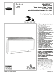
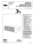
Download Carrier AQUAZONE 50PEC09-18 Product data
Transcript
Advance
Product
Data*
Aquazone™
50PEC09-18
Water Source Heat Pumps Console Unit
with Puron® Refrigerant (R-410A)
*For units purchased on or after June 23, 2014.
3/
4
to 11/2 Nominal Tons
TM
Single-package console water source
heat pump with self-contained line
voltage thermostats.
• Suitable for either geothermal or
boiler/tower applications with
operating temperature range from
25 F to 110 F.
• Thermostatic expansion valve (TXV)
• Rubber grommet mounted
compressors for quiet operation
• Sloped top cabinet
• Right or left hand piping connection
• Multiple unit-mounted and remote
thermostat options
• Adaptable cabinet and subbase
configurations
• Factory-mounted flow regulators and
control valves for easy installation
• Non-ozone depleting Puron
refrigerant (R-410A)
Features/Benefits
Carrier’s Aquazone console
water source heat pumps are
a flexible, attractive
alternative for all finished
interior space, under-window
style installations.
Operating efficiency
Aquazone water source heat pump
(WSHP) units are designed for quality
and performance excellence over their
lifetime. Units offer standard cooling
EERs (energy efficiency ratios) up to
13.3 for boiler/tower systems and as
high as 22.3 for geothermal applications. Heating COPs (coefficients of
performance) are as high as 4.6,
among the highest in the industry.
Quiet operation
The Carrier console WSHP provides
exceptionally quiet operation for maximum comfort.
© Carrier Corporation 2014
Form 50PEC-1APD
Features/Benefits (cont)
Design flexibility
Aquazone™ console WSHP units are
offered in 4 capacity sizes to meet individual zone needs efficiently and effectively. Standard and extended operating range units are available to suit a
variety of application requirements.
Safe, reliable operation
Standard safety features include: high
and low pressure monitoring and field
selectable water and air coil freeze protection sensing. All safety controls may
be reset at the thermostat. Each unit is
tested and run at the factory to ensure
proper operation of all components
and safety switches.
All components are carefully
designed and selected for endurance,
durability, and carefree day-to-day
operation.
The water-to-refrigerant heat
exchanger has copper inner and steel
outer tubing which is painted on the
outside to provide corrosion resistance
protection. Cupronickel heat exchangers are available and should be used on
all open loop applications.
Units are rated and certified in accordance with AHRI (Air-Conditioning,
Heating, and Refrigeration Institute)/
ISO (International Organization for
Standardization)/ASHRAE (American
Society of Heating, Refrigerating and
Air-Conditioning Engineers) 13256-1
performance standard, and are CSA
(Canadian Standards Association)/
NRTL (Nationally Recognized Testing
Lab) listed.
Installation ease
The unit is packaged for simple, low
cost handling, with minimal time re-
quired for installation. The console unit
arrives at the jobsite fully assembled to
minimize installation time and reduce
installation cost. All units are pre-wired
and factory charged with Puron® refrigerant (R-410A).
Water connections are available in a
variety of configurations direct from
the factory. The standard configuration
is 5/8 in. OD sweat connections for
maximum flexibility in the field. Additionally, factory-installed motorized water shutoff valves are available for use
on energy conserving systems employing a variable pumping technique.
The standard electrical connections
are made quickly and directly to a power distribution terminal block. To further improve installation efficiency, a
fused or unfused disconnect switch, as
well as a 20 amp plug and cord, are
available as factory-installed options.
A 3/4 in. ID vinyl condensate connection is provided for connection to
the field-installed condensate line.
Compact cabinet design dimensions are 12 in. deep, 48 in. wide and
24 in. tall. For flexibility, the controls
can be mounted on the top right or left
side. Additionally, the sloped top design discourages the use of the unit as
a shelf, preventing air blockage and
any spills from damaging the unit.
No-fuss maintenance and
serviceability
Large service access panels enable
quick inspection for problem solving
and the control box swings down for
easy access to the controls.
Fan motor sleeve bearings are permanently lubricated. If the unit requires
Table of contents
Page
Features/Benefits . . . . . . . . . . . . . . . . . . . . . . . . . . . . . . . . . . . . . . . . . . 1-3
Model Number Nomenclature . . . . . . . . . . . . . . . . . . . . . . . . . . . . . . . . . . .4
AHRI/ISO Capacity Ratings . . . . . . . . . . . . . . . . . . . . . . . . . . . . . . . . . . . .5
Physical Data . . . . . . . . . . . . . . . . . . . . . . . . . . . . . . . . . . . . . . . . . . . . . . .5
Options and Accessories . . . . . . . . . . . . . . . . . . . . . . . . . . . . . . . . . . . . . . .6
Dimensions . . . . . . . . . . . . . . . . . . . . . . . . . . . . . . . . . . . . . . . . . . . . . . 7,8
Performance Data . . . . . . . . . . . . . . . . . . . . . . . . . . . . . . . . . . . . . . . . 9-13
Application Data . . . . . . . . . . . . . . . . . . . . . . . . . . . . . . . . . . . . . . . . 14-17
Electrical Data . . . . . . . . . . . . . . . . . . . . . . . . . . . . . . . . . . . . . . . . . . . . .18
Guide Specifications . . . . . . . . . . . . . . . . . . . . . . . . . . . . . . . . . . . . . . 19-21
2
service, an easily removable cabinet
and slide-out fan section make access
simple.
Units are equipped with easily accessible service access ports on both
the suction and the discharge refrigerant lines for on-site testing and refrigerant recovery. Filter racks provide
easy filter access for cleaning.
Maximum control flexibility
Aquazone water source heat pumps
provide reliable control operation using
a standard microprocessor board with
flexible alternatives for many direct
digital controls (DDC) applications
including the Carrier Comfort
Network® (CCN) controls and open
protocol systems.
Carrier’s Aquazone unit solid-state
control system, the Complete C, provides control of the unit compressor,
reversing valve, fan, safety features,
and troubleshooting fault indication
features. The Complete C control system is a user friendly, low cost, advanced WSHP control board. Many
features are field selectable to maximize flexibility in field installation. The
overall features of this control system
include:
40-va transformer — Assists in
accommodating accessory loads.
Anti-short cycle timer — The timer
provides a minimum off time to prevent the unit from short cycling. The
5-minute timer energizes when the
compressor is deenergized, resulting in
a 5-minute delay before the unit can be
restarted. Thus, it prevents short
cycling of the compressor.
Random start relay — The random
start relay provides a random delay in
energizing each different WSHP unit.
This option minimizes peak electrical
demand during start-up from different
operating modes or after building
power outages. The control features a
5 to 80 second random start upon
start-up.
High and low pressure refrigerant
protection — Safeguards against
unreliable unit operation and prevents
refrigerant from leaking.
Condensate overflow sensor —
Electronic sensor mounted to the drain
pan. When condensate pan liquid
reaches an unacceptable level, the unit
is automatically deactivated and placed
in a lockout condition. The sensor
recognizes thirty continuous seconds
of overflow as a fault condition.
High and low voltage protection —
Safety protection for excessive or low
voltage conditions.
Automatic intelligent reset — Unit
shall automatically restart 5 minutes
after shutdown if the fault has cleared.
Should a fault occur 3 times sequentially, lockout will occur.
Accessory output — In applications
such as variable speed pumping, a
24-v output cycles a motorized water
valve or damper actuator with
compressor.
Performance monitor (PM) — This
feature monitors water temperatures to
warn when the heat pump is operating
inefficiently or beyond typical operating range. A field selectable switch initiates a warning code on the unit
display.
Water coil freeze protection
(selectable for water or antifreeze) — Field selectable switch for
water and water/glycol solution systems initiates a fault when temperatures exceed the selected limit for
30 continuous seconds.
Air coil freeze protection (check
filter operation) — Field selectable
switch for assessing excessive filter
pressure drop initiates a fault when
temperatures exceed the selected limit
for 30 continuous seconds.
Alarm relay setting — Selectable
24-v or pilot duty dry contact provides
remote alarm activation.
Service Test mode with diagnostic
LED (light-emitting diode) — Test
mode allows service personnel to
check the operation of the WSHP
and control system efficiently. Upon
entering Test mode, time delays speed
up, and the Status LED flashes a code
indicating the last fault. This mode
provides an easy fault diagnosis, based
on the fault code that the status LED
flashes. Carrier-provided troubleshooting tables provide an easy reference to
typical problems.
LED visual output — An LED panel
indicates high pressure, low pressure,
low voltage, high voltage, air/water
freeze protection, condensate overflow, and control status.
Puron® refrigerant (R-410A)
Puron refrigerant (R-410A) is a nonchlorine based enviromentally balanced, non-ozone depleting refrigerant. Puron refrigerant characteristics,
compared to R-22, have:
• Binary and near azeotropic mixture
of 50% R-32 and 50% R-125.
• Higher efficiencies (50 to 60%
higher operating pressures).
• Virtually no glide. Unlike other
alternative refrigerants, the two
components in Puron refrigerant
have virtually the same leak rates.
* Sponsored by ASHRAE (American Society of Heating,
Refrigerating and Air Conditioning Engineers.
† Registered trademark of Schneider Electric.
3
Model number nomenclature
50PEC 12
X
C
C
C 1
A P
C A
Factory Installed Options
Model Series
Standard Cleanable
Mesh Filter
50PEC – Aquazone™ High Efficiency
Water Source Heat Pump
with Puron® Refrigerant (R-410A)
09
12
15
18
– 3/4
– 1
– 11/4
– 11/2
Water Circuit Options
A – 5/8 in. Sweat, Right
H – 1/2 in. FPT Fitting, Right
T – 1/2 in. FPT Fitting, Left
X – 5/8 in. Sweat, Left
1
A
Operating Range/Sound Option
A – Extended Range
Packaging
1 – Domestic
A
Cabinet and Subbase Options
A – Standard 63 in. Cabinet and Subbase
T – No Cabinet and Standard Subbase
X – Standard 48 in. Cabinet and Subbase
W – No Cabinet and No Subbase
Voltage
0 – 115-1-60
3 – 208/230-1-60
4 – 277-1-60
B – 115-1-60 with Disconnect
C – 208/230-1-60 with Disconnect
D – 277-1-60 with Disconnect
L – Standard C Microprocessor Control Package with Remote Thermostat
R – Standard D Microprocessor Control Package with Remote Thermostat
U – Unit Mounted Controller
Refrigerant Circuit Options
E – Cu, Coated
J – CuNi, Coated
LEGEND
Cu
— Copper
CuNi — Copper Nickel
OA
— Outdoor Air
4
Std (No OA Damper)
OA Damper
AHRI/ISO capacity ratings
50PEC
UNIT SIZE
FLUID
FLOW
RATE
gpm
09
12
15
18
COP
db
EER
wb
—
—
—
—
2.0
2.5
4.0
5.0
WATER LOOP HEAT PUMP
Cooling 86 F
Capacity
Btuh
8,200
10,500
14,400
16,400
EER
12.9
12.0
13.3
12.3
GROUND WATER HEAT PUMP
Heating 68 F
Capacity
Btuh
9,400
12,400
15,000
17,500
COP
4.6
4.3
4.3
4.2
Cooling 59 F
Capacity
Btuh
10,200
13,000
16,400
18,300
LEGEND
Coefficient of Performance
Dry Bulb Temperature
Energy Efficiency Ratio
Wet Bulb Temperature
EER
22.3
19.4
19.8
17.6
Heating 50 F
Capacity
Btuh
7,400
10,900
11,800
14,600
COP
3.8
3.8
3.6
3.4
GROUND LOOP HEAT PUMP
Cooling 77 F
Capacity
Btuh
9,000
11,500
14,700
17,000
EER
16.0
14.2
14.5
14.0
Heating 32 F
Capacity
Btuh
5,400
8,400
9,800
12,000
COP
3.3
3.3
3.3
3.1
NOTES:
1. Ratings are in accordance with and certified to AHRI/ISO Standard 13256-1.
2. Cooling capacities based upon 80.6 F db, 66.2 F wb entering air
temperature.
3. Heating capacities based upon 68 F db, 59 F wb entering air temperature.
Physical data
BASE UNIT 50PEC
COMPRESSOR (1 each)
Maximum Water Working Pressure (psig/kPa)
09
Rotary
12
Rotary
15
Rotary
18
Rotary
400/3100
400/3100
400/3100
400/3100
PSC/2
PSC/2
PSC/2
PSC/2
1/10
1/10
1/4
PSC Fan Motor and Blower
Fan Motor Type/Speeds
Fan Motor (hp)
Blower Wheel Size (Dia x W) (in.) (qty)
5.5 x 8.0 (X 2)
WATER CONNECTION SIZE (in.)
0.15
Coaxial Coil Volume (gal)
Condensate Connection in. FPT
5.5 x 8.0 (X 2)
5.5 x 8.0 (X 2)
5/8 in. Sweat (Optional 1/2 in. FPT)
3/
4 ID
(1 OD)
0.15
3/
4 ID
(1 OD)
1/4
5.5 x 8.0 (X 2)
0.31
3/
4 ID
(1 OD)
0.31
3/
4 ID
(1 OD)
VERTICAL CABINET
Refrigeration Charge (oz)
Air Coil Dimensions (H x L)
19
22
23
23
10 x 27
10 x 27
10 x 27
10 x 27
7 x 311/4 x 3/8
7 x 311/4 x 3/8
7 x 311/4 x 3/8
7 x 311/4 x 3/8
Weight - Operating (lbs)
131
138
144
144
Weight - Shipping (lbs)
151
158
164
164
Std. Filter - 1/2" Washable Aluminum (H x L)
LEGEND
FPT — Female Pipe Thread
PSC — Permanent Split Capacitor
5
Options and accessories
Factory-wired options
Factory-installed options
Unit mounted controller is a factory-wired option. The
standard unit mounted controller provides a tactile touchpad for temperature, fan and mode adjustment as shown.
Temperature is read in a digital display, with an LED display indicating unit operating mode, as well as fan speed
and fault indication for high or low pressure lockout. Temperature set points are adjustable from 60 F to 80 F, with
an adjustable temperature differential between 1 F and 6 F.
Selectable options include manual or automatic changeover, high or low fan speed as well as constant fan operation or fan operation to cycle with the compressor.
Additional features include a 5 minute anti short cycling
delay, random start, 90 second low pressure bypass timer
and intelligent reset to allow the unit to automatically
restart after 5 minutes if a fault is no longer active.
Cupronickel heat exchangers are available for higher
corrosion protection for applications such as open tower,
geothermal, etc. Consult the water quality guidelines for
proper application and selection of this option.
Thermostat options include auto changeover (ACO)
thermostat. The thermostat sends the appropriate signal to
the controller for cooling or heating mode of operation.
Options R and L allow connection to a remote wallmounted thermostat. The controller requires a heat pump
thermostat. The controller can be configured for heat
pump or heat/cool thermostat.
Piping connections can be provided on either the right
or left hand side of the unit, for easy installation. Orientation is determined by facing the unit from the front side.
UNIT MOUNTED CONTROL
6
Field-installed accessories
Aquazone system control panel includes a preprogrammed, easy to use, Carrier Comfort Controller set
up for a WSHP system.
• Coordinates, monitors, and controls all WSHP units
and ancillary equipment including cooling towers, boilers, and system pumps.
• 50RLP model nomenclature is used to customize the
panel to control all WSHP system requirements.
• Panel can be ordered to include 2, 4, 6, or 8 stages of
system heat rejection.
• Panel can be ordered to include 2, 4, 6, or 8 stages of
system heat addition.
• Panel can be ordered with unique WSHP zone operation capabilities for stand alone systems (i.e., non-communicating) to control 10 or 18 zones of WSHP units.
• Panel can be ordered to control variable frequency cooling tower fan operation.
• System pumping operation can be configured for start/
stop, lead/lag, or variable frequency pump operation.
• Direct digital controls (DDC) are compatible using the
BACnet and WSHP units using WSHP Open.
Dimensions
50PEC09-18 UNIT CONSOLE
2.875
LEFT HAND WATER
CONNECTIONS
RIGHT HAND WATER
CONNECTIONS
6.00
45.00
45.00
6.00
6.125
23.875
12.875
30.75
3.375
48.00
15.875
48.00
30.75
11.00
12.00
NOTES: All dimensions within ± 0.125".
Filter size: 7" x 30 1/4" x 3/8" Aluminum Mesh
7
Dimensions (cont)
50PEC09-18 UNIT CHASSIS
LEFT HAND WATER
42.75
11.00
8.00
1.38
12.00
0.75
Water
Out
1.00
2.75
2.00
Water
In
19.56
Condensate
Water
15.63
13.75
13.50
5.00
1.75
3.38
1.63
RIGHT HAND WATER
Disconnect
Switch
0.75
42.75
11.00
4.88
8.00
2.75
Disconnect
Switch
0.75
2.00
Water In
15.63
1.00
Water Out
15.00
13.75
8.69
Condensate
Water
4.00
7.31
NOTES:
1. All dimensions are within ± 0.125 inch.
2. Console units must be installed with a cabinet and subbase.
3. Filter size: 7 x 30-1/8 x 38-in. Aluminum Mesh
4. Unit controller shown, other control options may have a different control panel configuration.
5. Specifications subject to change without notice.
8
Performance data
50PEC09 — COOLING, NOMINAL AIRFLOW 350 CFM, 2.0 GPM
EWT (F)
Entering Air
Temp (F)
Total Capacity
(MBtuh)
50
60
70
85
100
50
60
70
85
100
50
60
70
85
100
50
60
70
85
100
9.35
8.72
8.10
7.16
6.22
10.01
9.34
8.67
7.66
6.65
10.97
10.24
9.50
8.40
7.29
11.94
11.14
10.34
9.14
7.93
70° db
61° wb
75° db
63° wb
80° db
67° wb
85° db
71° wb
Sensible
Capacity
(MBtuh)
Sensible to Total
Ratio
6.22
5.86
5.50
4.99
4.49
7.42
6.98
6.56
5.95
5.34
8.17
7.69
7.22
6.55
5.89
8.94
8.41
7.90
7.17
6.44
0.67
0.67
0.68
0.70
0.72
0.74
0.75
0.76
0.78
0.80
0.74
0.75
0.76
0.78
0.81
0.75
0.75
0.76
0.78
0.81
Power Input
(kW)
Heat of Rejection
(MBtuh)
EER
0.38
10.66
24.4
0.45
10.25
19.5
0.51
0.60
0.70
0.39
0.45
0.51
0.61
0.70
0.39
0.45
0.52
0.61
0.71
0.39
0.46
0.52
0.62
0.72
9.84
9.22
8.60
11.33
10.87
10.42
9.74
9.05
12.30
11.78
11.27
10.49
9.71
13.27
12.69
12.11
11.25
10.38
15.9
11.8
8.9
26.0
20.8
16.9
12.6
9.5
28.2
22.6
18.4
13.7
10.3
30.5
24.4
19.8
14.8
11.1
50PEC09 — HEATING, NOMINAL AIRFLOW 350 CFM, 2.0 GPM
EWT (F)
Entering Air
Temp (F)
Total Capacity (MBtuh)
50
60
70
7.74
8.90
10.06
11.22
7.31
8.41
9.50
10.60
6.81
7.83
8.85
9.87
60°
80
50
60
70
70°
80
50
60
70
80°
80
Power Input (kW)
Heat of Abs. (MBtuh)
COP
0.53
5.92
4.3
0.57
6.96
4.6
0.60
0.64
0.54
0.58
0.61
0.65
0.56
0.59
0.63
0.67
8.00
9.04
5.46
6.43
7.41
8.38
4.91
5.81
6.71
7.60
4.9
5.2
3.9
4.3
4.5
4.8
3.6
3.9
4.1
4.3
50PEC09 — LOW TEMPERATURE HEATING*, NOMINAL AIRFLOW 350 CFM, 2.0 GPM
EWT (F)
Entering Air
Temp (F)
Total Capacity (MBtuh)
Power Input (kW)
Heat of Abs. (MBtuh)
4.74
5.31
6.45
4.48
5.01
6.09
4.17
4.67
5.67
0.44
3.22
3.1
0.46
3.73
3.4
0.50
0.45
0.47
0.51
0.46
0.48
0.52
4.75
2.93
3.41
4.36
2.59
3.02
3.90
3.8
2.9
3.1
3.5
2.6
2.8
3.2
25
30
40
60°
25
30
40
70°
25
30
40
80°
COP
* Antifreeze required.
LEGEND
COP — Coefficient of Performance
db
— Dry Bulb Temperature
EER — Energy Efficiency Ratio
EWT — Entering Water Temperature
MBtuh — Btuh in Thousands
wb
— Wet Bulb Temperature
9
Performance data (cont)
50PEC12 — COOLING, NOMINAL AIRFLOW 450 CFM, 2.5 GPM
EWT (F)
Entering Air
Temp (F)
Total Capacity
(MBtuh)
50
60
70
11.90
11.12
10.33
9.16
7.98
12.74
11.90
11.06
9.80
8.54
13.97
13.05
12.13
10.75
9.37
15.19
14.19
13.19
11.69
10.19
70° db
61° wb
85
100
50
60
70
75° db
63° wb
85
100
50
60
70
80° db
67° wb
85
100
50
60
70
85° db
71° wb
85
100
Sensible
Capacity
(MBtuh)
Sensible to Total
Ratio
7.92
7.46
7.02
6.39
5.76
9.44
8.89
8.37
7.61
6.86
10.40
9.80
9.22
8.39
7.56
11.37
10.71
10.08
9.17
8.27
0.67
0.67
0.68
0.70
0.72
0.74
0.75
0.76
0.78
0.80
0.74
0.75
0.76
0.78
0.81
0.75
0.75
0.76
0.78
0.81
Power Input
(kW)
Heat of Rejection
(MBtuh)
EER
0.58
13.88
20.5
0.65
13.35
17.0
0.73
0.84
0.95
0.58
0.66
0.73
0.84
0.96
0.59
0.66
0.74
0.85
0.96
0.59
0.67
0.74
0.86
0.97
12.82
12.02
11.23
14.73
14.15
13.56
12.69
11.81
15.98
15.31
14.65
13.65
12.66
17.22
16.48
15.73
14.62
13.51
14.2
10.9
8.4
21.8
18.1
15.1
11.6
8.9
23.7
19.7
16.4
12.6
9.7
25.6
21.2
17.7
13.6
10.5
50PEC12 — HEATING, NOMINAL AIRFLOW 450 CFM, 2.5 GPM
EWT (F)
Entering Air
Temp (F)
Total Capacity (MBtuh)
50
60
70
11.05
12.21
13.37
14.53
10.44
11.53
12.63
13.73
9.72
10.74
11.76
12.79
60°
80
50
60
70
70°
80
50
60
70
80°
80
Power Input (kW)
Heat of Abs. (MBtuh)
COP
0.78
8.38
4.1
0.81
9.43
4.4
0.84
0.87
0.80
0.83
0.86
0.89
0.82
0.85
0.88
0.91
10.49
11.54
7.72
8.71
9.70
10.68
6.94
7.85
8.76
9.67
4.6
4.9
3.8
4.1
4.3
4.5
3.5
3.7
3.9
4.1
50PEC12 — LOW TEMPERATURE HEATING*, NOMINAL AIRFLOW 450 CFM, 2.5 GPM
EWT (F)
Entering Air
Temp (F)
Total Capacity (MBtuh)
Power Input (kW)
Heat of Abs. (MBtuh)
7.98
8.55
9.69
7.54
8.08
9.16
7.02
7.52
8.53
0.70
5.58
3.3
0.72
6.10
3.5
0.75
0.72
0.73
0.77
0.73
0.75
0.78
7.13
5.09
5.58
6.54
4.52
4.96
5.85
3.8
3.1
3.2
3.5
2.8
2.9
3.2
25
60°
30
40
25
70°
30
40
25
80°
30
40
* Antifreeze required.
COP
db
EER
EWT
MBtuh
wb
10
—
—
—
—
—
—
LEGEND
Coefficient of Performance
Dry Bulb Temperature
Energy Efficiency Ratio
Entering Water Temperature
Btuh in Thousands
Wet Bulb Temperature
COP
50PEC15 — COOLING, NOMINAL AIRFLOW 550 CFM, 4.0 GPM
EWT (F)
Entering Air
Temp (F)
Total Capacity
(MBtuh)
50
60
70
14.79
14.08
13.37
12.31
11.24
15.83
15.07
14.31
13.17
12.03
17.35
16.52
15.69
14.44
13.19
18.88
17.97
17.07
15.71
14.35
70° db
61° wb
85
100
50
60
70
75° db
63° wb
85
100
50
60
70
80° db
67° wb
85
100
50
60
70
85° db
71° wb
85
100
Sensible
Capacity
(MBtuh)
9.84
9.45
9.09
8.58
8.11
11.73
11.26
10.82
10.22
9.66
12.92
12.41
11.93
11.27
10.65
14.13
13.57
13.04
12.32
11.65
Sensible to Total
Ratio
0.67
0.67
0.68
0.70
0.72
0.74
0.75
0.76
0.78
0.80
0.74
0.75
0.76
0.78
0.81
0.75
0.75
0.76
0.78
0.81
Power Input
(kW)
Heat of Rejection
(MBtuh)
EER
0.72
17.26
20.5
0.81
16.86
17.3
0.90
1.04
1.18
0.73
0.82
0.91
1.05
1.18
0.73
0.83
0.92
1.06
1.19
0.74
0.83
0.92
1.06
1.20
16.46
15.86
15.26
18.30
17.86
17.42
16.74
16.07
19.86
19.34
18.82
18.04
17.27
21.40
20.81
20.22
19.34
18.46
14.8
11.8
9.6
21.8
18.4
15.7
12.6
10.2
23.7
20.0
17.1
13.7
11.1
25.5
21.6
18.5
14.8
11.9
50PEC15 — HEATING, NOMINAL AIRFLOW 550 CFM, 4.0 GPM
EWT (F)
Entering Air
Temp (F)
Total Capacity (MBtuh)
50
60
70
12.75
14.26
15.77
17.28
12.05
13.48
14.90
16.33
11.22
12.55
13.88
15.21
60°
80
50
60
70
70°
80
50
60
70
80°
80
Power Input (kW)
Heat of Abs. (MBtuh)
COP
0.92
9.61
4.1
0.96
10.98
4.3
1.00
1.04
0.94
0.98
1.02
1.06
0.96
1.00
1.04
1.09
12.36
13.73
8.84
10.13
11.42
12.71
7.94
9.13
10.31
11.50
4.6
4.9
3.8
4.0
4.3
4.5
3.4
3.7
3.9
4.1
50PEC15 — LOW TEMPERATURE HEATING*, NOMINAL AIRFLOW 550 CFM, 4.0 GPM
EWT (F)
Entering Air
Temp (F)
Total Capacity (MBtuh)
Power Input (kW)
Heat of Abs. (MBtuh)
8.80
9.54
11.02
8.32
9.02
10.41
7.75
8.40
9.70
0.82
6.00
3.1
0.84
6.67
3.3
0.88
0.84
0.86
0.90
0.86
0.88
0.92
8.01
5.46
6.09
7.35
4.82
5.40
6.56
3.7
2.9
3.1
3.4
2.6
2.8
3.1
25
60°
30
40
25
70°
30
40
25
80°
30
40
COP
* Antifreeze required.
COP
db
EER
EWT
MBtuh
wb
—
—
—
—
—
—
LEGEND
Coefficient of Performance
Dry Bulb Temperature
Energy Efficiency Ratio
Entering Water Temperature
Btuh in Thousands
Wet Bulb Temperature
11
Performance data (cont)
50PEC18 — COOLING, NOMINAL AIRFLOW 600 CFM, 5.0 GPM
EWT (F)
Entering Air
Temp (F)
Total Capacity
(MBtuh)
Sensible
Capacity
(MBtuh)
16.26
15.65
15.05
14.14
13.23
17.40
16.76
16.11
15.13
14.16
19.08
18.37
17.66
16.59
15.52
20.76
19.98
19.21
18.04
16.88
10.82
10.51
10.23
9.86
9.54
12.89
12.52
12.18
11.74
11.37
14.21
13.79
13.42
12.94
12.53
15.54
15.08
14.68
14.15
13.70
50
60
70
70° db
61° wb
85
100
50
60
70
75° db
63° wb
85
100
50
60
70
80° db
67° wb
85
100
50
60
70
85° db
71° wb
85
100
Sensible to Total
Ratio
0.67
0.67
0.68
0.70
0.72
0.74
0.75
0.76
0.78
0.80
0.74
0.75
0.76
0.78
0.81
0.75
0.75
0.76
0.78
0.81
Power Input
(kW)
Heat of Rejection
(MBtuh)
EER
0.91
19.36
17.9
1.01
19.11
15.5
1.12
1.27
1.43
0.91
1.02
1.12
1.28
1.44
0.92
1.03
1.13
1.29
1.45
0.93
1.03
1.14
1.30
1.46
18.87
18.47
18.09
20.52
20.23
19.94
19.50
19.06
22.22
21.87
21.52
20.99
20.46
23.93
23.51
23.10
22.48
21.86
13.5
11.1
9.3
19.1
16.5
14.4
11.8
9.9
20.7
17.9
15.6
12.9
10.7
22.3
19.3
16.8
13.9
11.6
50PEC18 — HEATING, NOMINAL AIRFLOW 600 CFM, 5.0 GPM
EWT (F)
Entering Air
Temp (F)
Total Capacity (MBtuh)
50
60
70
15.37
16.96
18.56
20.16
14.52
16.03
17.54
19.04
13.52
14.93
16.33
17.74
60°
80
50
60
70
70°
80
50
60
70
80°
80
Power Input (kW)
Heat of Abs. (MBtuh)
COP
1.16
11.39
3.9
1.19
12.89
4.2
1.22
1.25
1.19
1.22
1.25
1.28
1.21
1.25
1.28
1.31
14.38
15.88
10.47
11.87
13.28
14.68
9.37
10.67
11.97
13.27
4.4
4.7
3.6
3.9
4.1
4.4
3.3
3.5
3.7
4.0
50PEC18 — LOW TEMPERATURE HEATING*, NOMINAL AIRFLOW 600 CFM, 5.0 GPM
EWT (F)
Entering Air
Temp (F)
Total Capacity (MBtuh)
Power Input (kW)
Heat of Abs. (MBtuh)
11.15
11.93
13.50
10.54
11.27
12.75
9.81
10.50
11.88
1.09
7.43
3.0
1.11
8.16
3.2
1.13
1.11
1.13
1.16
1.14
1.15
1.18
9.63
6.74
7.43
8.81
5.93
6.57
7.84
3.5
2.8
2.9
3.2
2.5
2.7
2.9
25
60°
30
40
25
70°
30
40
25
80°
30
40
* Antifreeze required.
COP
db
EER
EWT
MBtuh
wb
12
—
—
—
—
—
—
LEGEND
Coefficient of Performance
Dry Bulb Temperature
Energy Efficiency Ratio
Entering Water Temperature
Btuh in Thousands
Wet Bulb Temperature
COP
SOUND DATA — SOUND POWER LEVEL, CASING RADIATED
OCTAVE BAND SOUND POWER LEVELS db, RE 10-12 WATTS
50PEC
UNIT
125
250
500
1000
2000
4000
8000
09
64.5
59.0
47.0
43.0
34.0
30.0
27.5
AHRI Sound
Rating
Bels
5.643
12
65.0
57.5
52.0
44.0
37.0
32.5
27.5
6.008
15
61.5
60.5
53.5
49.5
42.5
39.5
35.0
6.069
18
69.5
62.0
54.5
51.0
45.0
39.5
34.0
6.363
13
Application data
Aquazone™ water source heat pump products are available
in a flexible, efficient array of models, which can be used in
all types of water loop, ground water, and ground loop
type systems. Use Aquazone products to provide optimal
energy efficient solutions and adapt to the most challenging design requirements.
AQUAZONE PRODUCT GUIDE
50 SERIES
50HQP,VQP
TYPE
SIZE (tons)
Large Capacity
6-10 (HQP)
61/2-25 (VQP)
50PC
Compact
11/4-5
50PS
Premium
Efficiency
1/ -6
2
High Efficiency
Console
3/ -11/
4
2
Premium
Efficiency
2-6
50PEC
50PT
50PSW
Water-to-Water
3-28
APPLICATION
Environmentally sound unit with Puron®
refrigerant (R-410A) designed to handle
large zoned areas for all geothermal and
boiler/tower applications.
Compact WSHP with Puron refrigerant
(R-410A) for boiler/tower, ground water, or
ground loop systems.
Premium, ultra efficient unit with Puron
refrigerant (R-410A) for new boiler/tower,
ground water, or ground loop systems.
Efficient console unit with Puron refrigerant
(R-410A) and attractive design for finished
interior, under-window installations.
Premium, ultra efficient 2-stage unit with
Puron refrigerant (R-410A) for new boiler/
tower, ground water, or ground loop
systems.
Efficient unit with Puron refrigerant
(R-410A) serves as an alternative to preheat or cool air. Unit can be used as a
stand-alone or supplemental boiler/chiller
in most hydronic heating applications. Also
conditions process fluids, lubricants, and
refrigerants.
Water loop system
Water loop (or boiler/tower) system applications typically
include a number of units plumbed to a common piping
system. For optimal performance, design this system between 2.25 and 3 gpm per ton of cooling capacity. The
system is comprised of highly efficient, packaged, reverse
cycle heat pump units, interconnected by a water loop.
The water circuit serves as both a sink and source for heat
absorption and rejection and is designed for entering water
temperatures between 50 F and 100 F. Within this temperature range, units can heat or cool from the same water
source. Transferring heat from warm to cold spaces in the
building, whenever they coexist, conserves energy rather
than creating new heat.
Refer to the Carrier Water Source Heat Pump System Design Guide for assistance designing water loop
systems. The guide includes a practical approach for the
latest and most current design recommendations including:
• Horizontal, vertical, console, rooftop and water-towater product applications.
• Ventilation methods and system design, including
energy recovery.
• Acoustical considerations for different product types.
• Addressing IAQ issues such as condensate removal,
humidity control.
• Air distribution design, including diffuser selection/
layout and ductwork design.
• Hydronic system design, including pipe sizing/layout
and boiler/tower sizing.
• Control configurations such as stand alone, DDC, DCV,
and VVT®.
• WSHP efficiency/operational cost comparison chart.
14
• System variations such as a system without a boiler,
variable pumping, and VAV for interior use.
Ground water systems
To use Aquazone units in ground water applications,
the extended range should be specified. This will provide
factory-installed coaxial coil insulation to prevent condensate from dripping when entering water temperatures are
below 50 F. In addition, the copper coaxial coil installed on
the Aquazone units may not be suitable for all water conditions. Refer to the Water Conditioning section for proper
coaxial coil material selection.
Surface water system — This system is typically located
near a lake or pond. In this application, the loop can be
submerged in a series of coils beneath the water surface.
The number of coils required depends on system load and
design. This application requires minimum piping and
excavation.
Open loop system — Use this system where ground
water is plentiful. In this application, ground water is
pumped through supply piping from the well to the building. The water is then pumped back into the ground
through a discharge well as it leaves the building. An additional heat exchanger is usually installed between the building water piping system and the ground water piping system. This design limits piping and excavation.
Aquazone units are rated to extremely low temperatures
to self-adjust the refrigeration circuit. Therefore, open loop
systems do not require water regulating valves. Use a slow
opening/closing solenoid valve to conserve water.
Ground loop systems
There are many commonly specified designs for ground
loop applications. Typical designs include vertical loops
and horizontal loops. In some applications, water is piped
from the ground or lake directly to the water source heat
pump. This system only requires piping to get the water
from the source to the unit.
NOTE: When using Aquazone water source heat pumps in
ground loop systems, refer to the design considerations in
the ground water system section.
Horizontal ground loop — Use this system when adequate space is available and trenching can be easily accomplished. A series of parallel pipes are laid out in trenches 3
to 6 feet below the ground surface, and then back-filled.
Often, multiple pipes are used to maximize each trench’s
heat transfer capability. Ground conditions, heating and
cooling requirements, and system design determine piping
requirements and ground loop field size.
Vertical ground loop — Use this system in vertical borehole applications. This design is well suited for retrofit
applications when space is limited or where landscaping is
already complete and minimum site disruption is desired.
The vertical ground loop system contains a single loop of
pipe inserted into a hole. The hole is back-filled and
grouted after the pipe is inserted. The completed loop is
concealed below ground. The number of loops required depends on ground conditions, heating and cooling requirements, and the depth of each hole.
Hybrid systems — In some applications, it may be beneficial to incorporate a cooling tower into the ground loop
system to reduce the overall cost. A hybrid system discards
excess heat into the air and increases the cooling performance of the ground loop.
Condensate drainage
Connect the console unit condensate drain to the building
condensate drain with a flexible, non-pressure rated plastic
hose. Be sure to avoid kinks in this hose to ensure an unobstructed flow of condensate from the unit to the drain.
The condensate hose’s horizontal run is usually too short
to pose any drainage problems; however, make sure this
line is pitched at least 1 in. for every 10 ft of run (in the direction of the flow.) Avoid low points and unpitched piping
since dirt collects in these areas and may cause stoppage
and overflow.
Installing a trap or drain in the field is not required unless
specified by local codes. The 50PEC units are designated
in a blow-thru configuration. The condensate drain pan is
located on the outlet side of the blower so that the pressure
in the drain pan is higher than the atmospheric pressure.
Water conditioning
In some applications, maintaining proper water quality
may require higher corrosion protection for the water-torefrigerant heat exchanger. Water quality varies from location to location and is unique for each job. Water characteristics such as pH value, alkalinity, hardness, and specific
conductance are important when considering any WSHP
application. Water typically includes impurities and hardness that must be removed. The required treatment depends on the water quality, as well as the system type. Water problems fall into three main categories:
1. Scale formation caused by hard water reduces the
heat transfer rate and increases the water pressure
drop through the heat exchanger. As water is heated,
minerals and salts are precipitated from a solution
and deposited on the inside surface of the pipe or
tube.
2. Corrosion is caused by absorption of gases from the
air coupled with water on exposed metal. Corrosion
is also common in salt-water areas.
3. Organic growths, such as algae, can reduce the heat
transfer rate by forming an insulating coating on the
inside tube surface. Algae can also promote corrosion
by pitting.
NOTE: In most commercial water loop applications, Aquazone™ WSHP units use a copper, water-to-refrigerant heat
exchanger. Units can also be equipped with a cupronickel
heat exchanger for applications where water is outside the
copper heat exchanger’s standard contaminant limits.
Acoustical design
Sound power levels represent the sound that the source,
the WSHP unit, produces with no regard to attenuation between the source and the space. Acoustical design goals
are necessary to provide criteria for occupied spaces.
These goals help ensure that people can be comfortable
and communicate effectively over the background noise of
the air-conditioning system and other background noise
sources.
Acoustical design goals are desirable sound pressure levels within a given conditioned space and are represented
by noise criteria (NC) curves. Noise criteria (NC) curve levels represent a peak over a full frequency spectrum. A high
value in a low frequency band has the same effect on NC
level as a lower value in a high frequency band. It is important that sound levels be balanced over the entire spectrum
relative to the NC curve. The lower the NC criteria curve,
the more stringent the room acoustical design must be to
meet the design goals.
It is important to know how to convert the unit ratings
from sound power (Lw) to sound pressure (Lp). This conversion depends on the specifics of the installation’s acoustical environment. Assessing an area’s acoustical design requires that you compare the sound pressure (Lp) with the
NC curve for the selected area.
The resulting calculations are compared to the NC curve
selected for the area to assess the acoustical design.
Some of the factors that affect conversion of sound
power to sound pressure and consequent NC level include:
• Type of acoustical ceiling
• Use of metal or flex duct
• Absorption in the occupied space
• Location in the occupied space
• Open or closed layout plan
• Use of open or ducted returns
• Orientation of unit to occupant
• Use of lined or unlined duct
OCTAVE BAND SOUND PRESSURE LEVEL (Lp)
ASSOCIATED WITH NC CURVES
NOISE
CRITERIA
CURVES
NC-15
NC-20
NC-25
NC-30
NC-35
NC-40
NC-45
NC-50
NC-55
NC-60
NC-65
OCTAVE BAND SOUND PRESSURE LEVEL (Lp)
Frequency (Hz)
63 125 250 500 1000 2000 4000 8000
49
36
26
17
17
14
12
11
52
41
33
27
22
19
17
16
54
45
38
31
27
24
22
21
58
49
41
36
31
29
28
27
61
53
45
40
36
34
33
32
64
57
50
45
41
39
38
37
67
61
54
49
46
44
43
42
71
64
58
54
51
49
48
47
74
68
63
58
56
54
53
52
77
71
67
63
61
59
58
57
80
75
71
68
66
64
63
62
15
Application data (cont)
WATER QUALITY GUIDELINES
CONDITION
HX MATERIAL*
CLOSED
RECIRCULATING†
OPEN LOOP AND RECIRCULATING WELL**
Scaling Potential — Primary Measurement
Above the given limits, scaling is likely to occur. Scaling indexes should be calculated using the limits below.
pH/Calcium
All
N/A
pH < 7.5 and Ca Hardness, <100 ppm
Hardness Method
Index Limits for Probable Scaling Situations (Operation outside these limits is not recommended.)
Scaling indexes should be calculated at 150 F for direct use and HWG applications, and at 90 F for indirect HX use. A monitoring plan should be implemented.
Ryznar Stability Index
6.0 - 7.5
All
N/A
If >7.5 minimize steel pipe use.
Langelier Saturation Index
–0.5 to +0.5
All
N/A
If <–0.5 minimize steel pipe use.
Based upon 150 F HWG and direct well, 85 F indirect well HX.
Iron Fouling
Iron Fe2+ (Ferrous)
<0.2 ppm (Ferrous)
All
N/A
(Bacterial Iron Potential)
If Fe2+ (ferrous) >0.2 ppm with pH 6 - 8, O2<5 ppm check for iron bacteria.
Iron Fouling
<0.5 ppm of Oxygen
All
N/A
Above this level deposition will occur.
Corrosion Prevention††
pH
6 - 8.5
6 - 8.5
All
Monitor/treat as needed.
Minimize steel pipe below 7 and no open tanks with pH <8.
<0.5 ppm
Hydrogen Sulfide (H2S)
At H2S>0.2 ppm, avoid use of copper and cupronickel piping or HXs.
All
N/A
Rotten egg smell appears at 0.5 ppm level.
Copper alloy (bronze or brass) cast components are okay to <0.5 ppm.
Ammonia Ion as Hydroxide,
<0.5 ppm
Chloride, Nitrate and Sulfate
All
N/A
Compounds
Maximum Chloride Levels
Maximum allowable at maximum water temperature.
50 F (10 C)
75 F (24 C)
100 F (38 C)
Copper
N/A
<20 ppm
NR
NR
Cupronickel
N/A
<150 ppm
NR
NR
304 SS
N/A
<400 ppm
<250 ppm
<150 ppm
316 SS
N/A
<1000 ppm
<550 ppm
<375 ppm
Titanium
N/A
>1000 ppm
>550 ppm
>375 ppm
Erosion and Clogging
Particulate Size and Erosion
<10 ppm of particles and a
maximum velocity of 6 fps. <10 ppm (<1 ppm “sandfree” for reinjection) of particles and a maximum
All
velocity of 6 fps. Filtered for maximum 800 micron size. Any particulate that
Filtered for maximum
is not removed can potentially clog components.
800 micron size.
Brackish
Use cupronickel heat exchanger when concentrations of calcium or
All
N/A
sodium chloride are greater than 125 ppm are present. (Seawater is
approximately 25,000 ppm.)
LEGEND
HWG — Hot Water Generator
HX — Heat Exchanger
N/A — Design Limits Not Applicable Considering Recirculating
Potable Water
NR — Application Not Recommended
SS
— Stainless Steel
*Heat exchanger materials considered are copper, cupronickel, 304 SS
(stainless steel), 316 SS, titanium.
†Closed recirculating system is identified by a closed pressurized piping
system.
**Recirculating open wells should observe the open recirculating design
considerations.
16
††If the concentration of these corrosives exceeds the maximum allowable
level, then the potential for serious corrosion problems exists.
Sulfides in the water quickly oxidize when exposed to air, requiring that no
agitation occur as the sample is taken. Unless tested immediately at the
site, the sample will require stabilization with a few drops of one Molar
zinc acetate solution, allowing accurate sulfide determination up to
24 hours after sampling. A low pH and high alkalinity can cause system
problems, even when both values are within ranges shown. The term pH
refers to the acidity, basicity, or neutrality of the water supply. Below 7.0,
the water is considered to be acidic. Above 7.0, water is considered to be
basic. Neutral water registers a pH of 7.0.
To convert ppm to grains per gallon, divide by 17. Hardness in mg/l is
equivalent to ppm.
WSHP sound control
Analyzing the projected sound level in the conditioned
space caused by a WSHP unit is quite involved. The key is
to have good sound power ratings (Lw) in dB on the equipment to determine the ductwork, ceiling and room sound
attenuation effect.
Console units
With console units, the fan and compressor are located
within the space, and only the casing design attenuates the
transmission of sound sources into the space. The designer
should carefully review the manufacturer’s acoustical data
when selecting console units and use lower fan speeds to
minimize space noise.
Operating limits
Environment
This equipment is designed for indoor installation ONLY.
Power supply
A voltage variation of ± 10% of nameplate utilization voltage is acceptable.
AIR LIMITS
AIR LIMITS
COOLING
Minimum ambient air temperature F
Maximum ambient air temperature F
Minimum evaporator entering air db/wb F
Rated air coil entering air db/wb F
Maximum evaporator entering air db/wb F
Minimum water coil entering fluid temperature F
Water loop typical coil entering fluid range temperature F
Maximum water coil entering fluid temperature F
HEATING
Minimum ambient air temperature F
Maximum ambient air temperature F
Minimum evaporator entering air db F
Rated air coil entering air F
Maximum evaporator entering air db F
Normal water coil entering fluid range F
Minimum water coil entering Fluid F
EXTENDED
RANGE
OPTION
50
100
68/57
80/67
98/85
50
70/90
110
40
85
50
68
80
25-80*
20*
LEGEND
db — Dry Bulb
wb — Wet Bulb
*Antifreeze solution is required at these fluid temperatures.
Starting conditions
Freeze protection
The 50PEC unit will start and operate in an ambient temperature of 50 F, with entering-air temperature at 50 F,
with entering-water temperature at 60 F, with both air and
water at the flow rates used in the AHRI/ISO Standard
13256-1 rating test, for initial start-up in winter.
NOTE: These are not normal or continuous operating
conditions. Such a start-up should be used to bring the
building space up to occupancy temperature.
Applications where systems are exposed to outdoor
temperatures below freezing (32 F) must be protected from
freezing. The most common method of protecting water
systems from freezing is adding glycol concentrations into
the water. Use design care when selecting both the type
and concentrations of glycol due to the following:
• Equipment and performance may suffer with high concentrations of glycol and other antifreeze solutions
• Loss of piping pressure may increase greatly, resulting
in higher pumping costs
• Higher mixture viscosity may cause excess corrosion
and wear on the entire system
• The water’s acidity may be greatly increased, promoting
corrosion
Glycol promotes galvanic corrosion in systems of dissimilar
metals. The result is corrosion of one metal by the other,
causing leaks.
17
Electrical data
50PEC
UNIT SIZE
09
12
15
18
FLA
HACR
LRA
RLA
18
—
—
—
—
VOLTAGE
v-ph-Hz
115-1-60
208/230-1-60
265-1-60
115-1-60
208/230-1-60
265-1-60
115-1-60
208/230-1-60
265-1-60
208/230-1-60
265-1-60
QTY
1
1
1
1
1
1
1
1
1
1
1
COMPRESSOR
RLA
7.0
3.4
2.9
9.6
4.6
3.8
12.7
5.6
4.6
7.4
6.0
LEGEND
Full Load Amps
Heating, Air Conditioning and Refrigeration
Locked Rotor Amps
Rated Load Amps
LRA
45.6
22.2
18.8
58.4
27.9
22.2
63.0
29.0
20.0
33.0
28.0
QTY
1
1
1
1
1
1
1
1
1
1
1
BLOWER
FLA
2.1
0.7
1.0
2.1
0.7
1.0
1.3
0.8
0.8
0.8
0.8
HP
0.10
0.10
0.10
0.10
0.10
0.10
0.25
0.25
0.25
0.25
0.25
MIN CIRCUIT MAX FUSE/
AMPS
HACR
10.9
5.0
4.6
14.1
6.5
5.8
17.2
7.8
6.6
10.1
8.3
15
15
15
20
15
15
25
15
15
15
15
Guide specifications
Console Water Source Heat Pumps
HVAC Guide Specifications
Size Range: 6,220 to 20,760 Btuh
Cooling Capacity
6,810 to 20,160 Btuh
Heating Capacity
Carrier Model Number: 50PEC
Part 1 — General
1.01 SYSTEM DESCRIPTION
A. Install water source heat pumps, as indicated on the
plans with capacities and characteristics as listed in
the schedule and the specifications that follow.
B. Units shall be individually packaged with wooden
skid covered with protective corner posts and plastic
stretch wrapping for maximum protection.
1.02 QUALITY ASSURANCE
A. All equipment listed in this section must be performance rated and certified in accordance with
AHRI/ISO Standard 13256-1, latest edition, and
safety listed in accordance with NRTL or CSA. All
units shall have AHRI/ISO and NRTL or CSA
labels.
B. All units shall be factory tested under normal operating conditions at nominal water flow rates. Units
which are tested without water flow are not acceptable. Standard operating range is 50 to 100 F entering water temperature.
Part 2 — Product
2.01 EQUIPMENT
A. Heat Pump Assembly:
Factory-tested and assembled single-piece packaged
heating and cooling heat pump units shall be factory
wired, charged with Puron® refrigerant (R-410A),
contain refrigerant-to-water heat exchanger, air-torefrigerant heat exchanger, 4-way reversing valve,
fan motor assembly, compressor, thermostatic
expansion valve (TXV) metering device, and all internal controls and safety devices.
B. Unit Cabinet:
1. The cabinet shall be constructed of heavy gage
steel with welded corner bracing. A removable
front cabinet allows easy service access to the
chassis. The cabinet shall have a 30-degree
sloped top with an aluminum rigid bar type discharge grille.
2. An access door shall be provided to cover the
swing down control section.
3. Options include a bottom return with left or
right hand configurations for ease of installation. Available with 3.375 in. subbase (bottom
return units only), with or without motorized
damper.
4. The cabinet shall be powder painted.
C. Fan and Motor Assembly:
The fan motors shall be multi-speed permanently
lubricated, PSC (permanent split capacitor) type
with thermal overload protection. To facilitate field
service all units shall have a motor and blower that
are removable without removing the chassis.
D. Refrigerant Components:
1. Units shall have a sealed refrigerant circuit including a rotary compressor, a refrigerant metering
device, a finned tube refrigerant-to-air heat
exchanger, a reversing valve, a coaxial (tube-intube) refrigerant-to-water heat exchanger, and
safety controls including a high-pressure sensor, a
loss-of-charge sensor to protect against loss of
refrigerant, and low water temperature (freezestat) sensor.
2. Rotary compressors shall have thermal overload protection and shall be located in an
insulated compartment to minimize sound
transmission. Units shall have the compressor
mounted on isolators to reduce noise and vibration transmission.
3. Refrigerant-to-air heat exchangers shall utilize
enhanced aluminum fins and rifled copper tube
construction rated to withstand 600 psig refrigerant working pressure.
4. Refrigerant-to-water heat exchangers shall be of
copper inner water tube and steel refrigerant
outer tube design rated to withstand 600 psig
working refrigerant pressure.
5. Drain pan shall be constructed of stainless steel
and have powder coated application to inhibit
corrosion.
6. Reversing valve shall be four-way solenoidactivated refrigerant valves which shall fail to
heating operation. If the unit fails to cooling a
low-temperature thermostat must be provided
to prevent over-cooling of the room.
7. Optional coaxial water-to-refrigerant heat
exchangers shall be cupronickel.
8. Standard extended range for units operating
with entering water temperatures below dew
point. For use in operating range with entering
water temperatures from 25 to 110 F.
E. Controls and Safeties:
Units which may be reset at the disconnect switch
only shall not be acceptable.
1. Electrical:
A control box shall be located within the unit
and shall contain controls for compressor,
reversing valve and fan motor operation.
2. Piping:
a. Copper tubes with a 5/8-in. OD dimension
shall be provided on the supply and return
water connections for the purpose of
forming a sweat connection to field-supplied
distribution piping.
b. Optional threaded connections: A 1/2-in.
female pipe threaded fitting shall be factory
19
Guide specifications (cont)
mounted on the supply and return water
connections.
3. Unit Controls:
Safety devices on all units shall include lowpressure sensor or loss-of-charge switch, highpressure switch, low water temperature sensor,
and condensate overflow switch.
4. The standard unit mounted controller shall provide a tactile touchpad for temperature, fan and
mode adjustment and provide a digital display
of temperature in either degrees Fahrenheit or
Celsius. The unit mounted controller shall provide an LED display for indication of unit operating mode as well as fan speed and fault
indication for high or low pressure lockout.
Options and features shall include:
a. Adjustable temperature set point from 60 F
through 80 F (15.5 C through 26.7 C)
b. Adjustable temperature differential between
1 F and 6 F (0.6 C and 3.3 C)
c. Manual or automatic changeover
d. High and low fan speed control
e. Constant fan speed or fan speed cycling with
compressor
f. A 5 minute anti-short cycling delay
g. Random start
h. A 90 second low pressure bypass timer
i. Intelligent reset to allow unit to automatically
restart after 5 minutes if a fault is no longer
active
5. The optional Complete C electronic control
system shall interface with the remote heat
pump (Y,O) wall thermostat (mechanical or
electronic). The control system shall have the
following features:
a. 50 va transformer.
b. Anti-short cycle time delay on compressor
operation; time delay shall be 5 minutes
minimum.
c. Random start on power-up.
d. Low voltage protection.
e. High voltage protection.
f. Condensate overflow shutdown.
g. Unit shutdown on low refrigerant pressures.
h. Unit shutdown on high or low water temperature (selectable for antifreeze solutions).
i. Option to reset unit at thermostat or disconnect. Fault type shall be retained in memory
if reset at thermostat.
j. Automatic intelligent reset. Unit shall automatically restart 5 minutes after shutdown if
the fault has cleared. Should a fault occur
3 times sequentially, then lockout will occur.
k. Ability to defeat time delays for servicing.
20
l. Light-emitting diode (LED) to indicate high
pressure, low pressure, improper voltage,
water coil freeze protection, air coil freeze
protection, condensate overflow, and control status.
m. Unit performance monitor to indicate inefficient operating conditions prior to unit
lockout.
n. Remote fault type indication at thermostat.
o. Single harness connection for all safety
devices.
p. Selectable 24-v or pilot duty dry contact
alarm output.
q. 24-v output to cycle a motorized water valve
with compressor contactor.
r. The control box components shall be
easily accessible with a swing out control
compartment.
6. The optional Deluxe D electronic control shall
have all the features of the Complete C control,
with the following additional features:
a. 75 va transformer.
b. A removable thermostat connector.
c. Random start on return from night setback.
d. Minimized reversing value operation for
extended life and quiet operation.
e. Night setback control from low temperature
thermostat, with 2-hour override initiated by
a momentary signal from the thermostat.
f. Dry contact night setback output for digital
night setback thermostats.
g. Ability to work with heat/cool (Y, W)
thermostats.
h. Ability to work with heat pump thermostats
using O or B reversing valve control.
i. Single grounded wire to initiate night setback or emergency shutdown.
j. Boilerless system control can switch automatically to electric heat at low loop water
temperature.
k. Control board shall allow up to 3 units to be
operated from one thermostat without any
auxiliary controls.
l. A relay to operate an external damper. The
control to be such that the damper will not
open until 30 minutes after the unit comes
back from Unoccupied mode.
m. Fan speed selection at thermostat.
n. A relay to restart a central pump or control a
24-v motorized water valve.
o. Intelligent fan speed selection based upon
thermostat demand and/or dehumidistat
signal.
7. Optional Controls:
a. Units designed for connection to remote wall
mounted thermostat shall be wired such that
the operating controls are at the thermostat.
The controller shall be provided with a low
voltage field wiring terminal block. The control scheme shall accommodate MCO or
ACO heat pump thermostats with Y, G, and
O outputs. An alternate controller shall be
available from the factory to accommodate
the Heat/Cool thermostats.
b. Fresh air dampers shall be motorized with a
spring return. The damper shall open when
Cooling or Heating mode selection is made
from the unit-mounted switches. With a
remote thermostat, the damper shall open
any time the fan is in operation.
F. Electrical Requirements:
1. A control box shall be located within the unit
compressor compartment and shall contain a
40 va transformer, 24-volt activated, 3-pole
compressor contactor, terminal block for
thermostat wiring and solid-state controller for
complete unit operation. Electro-mechanical
operation WILL NOT be accepted.
2. Units shall be nameplated for use with timedelay fuses or HACR circuit breakers.
3. Unit controls shall be 24-volt and provide heating
or cooling as required by the remote thermostat.
G. Special Features:
1. Aquazone™ Thermostat Controls (for use with
remote thermostat units):
a. Programmable multi-stage thermostat with
7-day clock, holiday scheduling, large backlit
display and remote sensor capability.
b. Programmable 5-day thermostat offers
2-stage heat, 2-stage cool, auto changeover,
5-minute built-in compressor protection, locking cover included.
c. Non-programmable thermostat with 2 heat
stages, 2 cool stages, auto changeover,
5-minute built-in compressor protection, locking cover included.
2. An Aquazone™ system control panel as specified in 50RLP Product Data (525-00040) is
available.
3. Evaporator coil protection shall be factory
installed to provide protection from corrosion in
coastal areas, marine applications or other
areas in which corrosion may be an issue.
21
Carrier Corporation • Syracuse, New York 13221
6-14
Manufacturer reserves the right to discontinue, or change at any time, specifications or designs without notice and without incurring obligations.
Pg 24
Catalog No. 04-52500076-01
Printed in U.S.A.
Form 50PEC-1APD
Replaces: NEW


