1
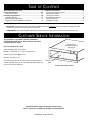
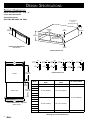
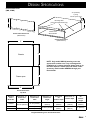
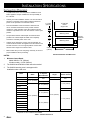
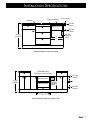
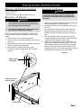
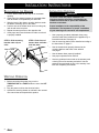
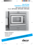
I n sta l l ati o n I n stru c ti o n s
Wa r m i n g O v en
For use with models:
EW, EWO
MW, MWO
PW, PWO
IWO, IOWO
Part No. 65034 Rev. K
Table
of
Important Safety Instructions...................................................... 1
Design Specifications................................................................2-3
Product Dimensions..................................................................2-3
Installation Specifications.........................................................4-6
Installation Planning..................................................................4-5
Power Supply Requirements....................................................... 6
Installing the Support Platform in the Cabinet.............................6
Contents
Installation Instructions.............................................................7-8
Verifying the Package Contents..................................................7
Removing the Drawer.................................................................. 7
Installing the Chassis................................................................... 7
Re-Installing the Drawer.............................................................. 8
Verifying Operation......................................................................8
Installation Checklist....................................................................8
IMPORTANT:
◊
INSTALLER: In the interest of safety, read these installation instructions completely before you begin the installation process.
Leave these installation instructions with the homeowner.
◊
HOMEOWNER: Keep these installation instructions for future reference. Save them for the local electrical inspector’s use.
Customer Service Information
Any questions or problems with this installation
should be directed to your Dacor dealer or the Dacor
Customer Service Team.
Warming Oven
with Drawer Removed
(see page 6)
Dacor Customer Service Team
(800) 793-0093 (U.S.A. and Canada)
Monday — Friday 6:00 a.m. to 5:00 p.m. Pacific Time
E-mail: [email protected]
Web site: www.Dacor.com
If the unit requires service, be sure to have the model and serial
number available when you call. The model and serial number are
found on the product data label.
Product Data
Label
Product Data Label Location
All specifications subject to change without notice.
Dacor® assumes no liability for changes to specifications.
© 2006 Dacor, all rights reserved.
Important Safety Instructions
Important Information About
Safety Instructions
Safety Symbols and Labels
DANGER
Important Safety Instructions and warnings appearing in these
instructions are not meant to cover all possible conditions and
situations that can occur. Common sense, caution and care
must be exercised when installing, maintaining or operating an
appliance.
Immediate hazards that WILL result in severe personal injury or
death.
WARNING
Hazards or unsafe practices that COULD result in severe
personal injury or death.
Installation should be done by a qualified installer.
CAUTION
Always contact Dacor about problems or conditions you do not
understand.
Hazards or unsafe practices that COULD result in minor
personal injury or property damage.
General Safety Precautions
To reduce the risk of fire, electric shock, serious injury or death when installing or using this appliance, follow basic safety
precautions, including the following:
WARNING
1.
Read all instructions before using the appliance.
11. Keep the electrical cord away from heated surfaces.
2.
This appliance must be grounded. Connect only
to a properly grounded outlet. See “Grounding
Instructions.”
12. Some products, such as whole eggs and sealed
containers such as closed glass jars may explode
and should not be heated in this oven.
3.
Install or locate this appliance only in accordance
with these installation instructions.
4.
Use this appliance only for its intended use as
described in this manual. Do not use corrosive
chemicals or vapors in this appliance. This type of
oven is specifically designed to heat and cook food.
It is not designed for industrial or laboratory use.
13. To reduce the risk of fire in the oven cavity: Do not
overcook food. Carefully attend the appliance if
paper, plastic or other combustible materials are
placed inside the oven.
14. If materials inside the oven should ignite, keep the
oven drawer closed and shut off the power at the fuse
or the circuit breaker panel.
5.
As with any appliance, close supervision is
necessary when used by children.
15. Only model IOWO24 is approved for use in outdoor
applications and near water (bathrooms).
6.
Do not operate this appliance if it has a damaged
electrical cord or plug, if it is not working properly or
if it has been damaged or dropped.
16. Model IOWO24, when installed as a towel warmer,
must have the wire rack (supplied with the product)
installed in the drawer bottom. Secure the rack with
with a screw and clip supplied with the rack.
7.
This appliance should be serviced only by qualified
service personnel. Contact the nearest Dacor
Authorized Servicer at (800) 793-0093, or at www.
Dacor.com for examination, repair or adjustment.
8.
Do not cover or block any openings on the
appliance.
9.
Do not store or use this appliance outdoors, except
as noted in these instructions. Do not use this
product near water – for example, near a kitchen
sink, in a wet basement or near a swimming pool,
etc.
10. Do not immerse the electrical cord or plug in water.
1
Design Specifications
Product Dimensions
NOTE: All tolerances are + 1/16,” - 0”
unless otherwise stated.
Overall Dimensions
(EW, EWO, MW, MWO, PW, PWO)
40" (1016mm)
3 prong
120 Vac power cord
Mounting
holes
10 1/8"
(257mm)
9"
(229mm)
1/2"
(13mm)
10"
(254mm)
Chassis view
without drawer
1/2"
(13mm)
Drawer Face Dimensions
(MW Shown)
Chassis Dimensions
D
E
3 5/16"
(84mm)
EWO
1"
(25mm)
Chassis
1"
(25mm)
PWO
1 5/16"
(33mm)
1"
(25mm)
23 1/16"
(586mm)
5/64"
(2mm)
Drawer open
2 3/16"
(56mm)
23 13/16”
(605mm)
EW
MWO
3 7/16"
(87mm)
1"
(25mm)
PW
3 1/4"
(83mm)
MW
2 1/4"
(57mm)
1 5/32"
(29mm)
1 1/8"
(29mm)
Handle Dimensions
Model
“C” Drawer Face
Width
“D” Chassis Face
Width
“E” Chassis Width
EWO24
23 7/8” (606mm)
23 11/16” (602mm)
22 3/16” (564mm)
26 7/8” (683mm)
26 11/16” (678mm)
EW27
EWO27
MW27
MWO27
PW27
EW30
C
Overall Dimensions - Top View
(EWO shown)
25 3/16” (640mm)
EWO30
MW30
MWO30
29 7/8” (759mm)
29 11/16” (754mm)
35 7/8” (911mm)
35 11/16” (906mm)
PW30
PWO30
EWO36
Warming Oven Overall Dimensions
2
34 1/4” (870mm)
Design Specifications
Overall Dimensions
(IWO, IOWO)
40" (1016mm)
3 prong
120 Vac power cord
Mounting holes
(rear holes IOWO model only)
F
C
Chassis view
without drawer
Drawer Face Dimensions
(IWO Shown)
Chassis Dimensions
(IOWO Shown)
E
Chassis
K
G
NOTE: Only model IOWO24 warming ovens are
approved for outdoor use. They are designed for
installation of a custom designed drawer front or for
the Dacor Epicure® drawer front and handle. Order
accessory model number AEWP24 through your
Dacor dealer.
Drawer open
J
C
Overall Dimensions
Top View
Warming
Oven
Model No.
IOWO24
Dimension “C”
Drawer face
width
22 5/16” (567mm)
IWO24
IWO27
Dimension “E”
Chassis face
width
Dimension “F”
Drawer face
height
Dimension
“G”
Chassis depth
Dimension “J”
Drawer depth
Dimension
“K”
Chassis
height
22 1/2” (572mm)
11 13/16”
(300mm)
19 3/4”
(502mm)
18 13/16”
(478mm)
11 7/8”
(302mm)
8 15/16” (227mm)
23 1/16”
(586mm)
23 13/16”
(605mm)
9” (229mm)
22 3/8” (568mm)
25 5/16” (643mm)
25 3/8” (645mm)
Integrated Warming Oven Overall Dimensions
3
Installation Specifications
Installation Planning
◊
A qualified technician must complete the installation of this
built-in appliance. Proper installation is the responsibility of
the customer.
◊
Carefully check the installation location. The oven should be
placed for convenient access. Make certain that electrical
power can be provided in the selected location.
◊
Plan the installation so that all minimum clearances are
met or exceeded. Dimensions shown provide minimum
clearances, unless otherwise noted. Be certain that proper
clearance is provided for the oven door when it is in the open
position.
◊
The specified minimum cabinet depth and width must be
provided. The cabinet depth and width must completely
enclose the recessed portion of the oven.
◊
Cabinet cutout dimensions must be used as indicated. All
contact surfaces between the appliance and the cabinet must
be solid and level. The oven support platform must be flush
with the bottom edge of the cabinet cutout.
◊
Warming Oven
C
D
Make certain that you have everything necessary to ensure a
proper installation before proceeding.
Warming Oven
C
Toe Kick
5/8” Min.
(16mm)
A
Stacked Installation with Wall Oven
NOTES:
1.
27"/30"/36"
Dacor
single oven
1 ¾” Min.
(44mm)
Minimum Cutout Depth:
Model IOWO24 - 20” (508mm)
All other models - 23 3/8” (594mm)
2.
The IOWO24 and EWO36 models cannot be stacked.
3.
The IOWO24 warming oven is not approved for
installation under a wall oven.
Model
IOWO24
IWO24
EWO24
“A” Cutout
Width
22 9/16” (573mm)
22 1/2” (572mm)
EW27
“B” Min. Width
to Adjacent
Doors/Drawers
N/A*
“C” Cutout
Height
12 1/8” (308mm)
IWO27
N/A*
24 1/4” (616mm)
1 1/16” (27mm)
27 1/4” (692mm)
EWO27
“D” Min. Gap
Between Cutouts
N/A*
N/A*
MW27
MWO27
PW27
EW30
27 1/4” (692mm)
9 1/8” (232mm)
25 1/2” (648mm)
EWO30
1 1/16” (27mm)
MW30
30 1/4” (768mm)
MWO30
PW30
PWO30
EWO36
34 3/8” (873mm)
36 1/4” (921mm
* Depends on size of cabinet face installed.
Table 1: Cutouts Dimensions
4
3” (76mm)
120 Vac
electrical
outlets
Installation Specifications
Typical countertop
Cooktop
1 1/2" (38mm)
Warming Oven
C
3/4" Min.
(19mm)
5/8" Min.
(16mm)
36" Typ.
(914mm)
A
B
120 Vac
electrical
outlet
Single Installation to Side of Cooktop
OB Outdoor Grill
EG Epicure Gas Cooktop
Warming Oven
36" typ.
(914mm)
Warming Oven
C
120 Vac
electrical
outlet
3/4" Min.
(19mm)
D
C
5/8" Min.
(16mm)
A
B
Stacked Installation Below Cooktop or Grill
5
Installation Specifications
Power Supply Requirements
The correct voltage, frequency and amperage must be supplied
to the electrical outlet from a grounded, single phase circuit that is
protected by a properly sized circuit breaker or time-delay fuse.
WARNING
Electric shock Hazard – This appliance is equipped
Circuit Requirements:
with a 40” (1016mm) power cord with a three prong
grounded plug. Plug it only into a grounded three prong
electrical outlet.
◊
Total Connected Load:
◊ Model EWO36: 0.8kW (6.5 Amp.)
◊ All other models: 0.5kW (4 Amp.)
• Do not remove the ground prong.
• Do not use a 2-prong adapter.
• Do not use an extension cord.
NOTES:
• Do not use a power cord that is frayed or
damaged.
Failure to comply with the above can result in fire,
electric shock, or death.
The electrical outlet for this appliance must only be
installed by a licensed electrician.
Power cord with
three-prong grounding plug
Grounding type
electrical outlet
Installing the Support Platform
the Cabinet
in
Provide a platform (100lb. load capacity) within the cabinet upon
which the warming oven will be supported. The platform must
be installed level and straight. The top edge of the platform must
be flush with the cutout at the front of the cabinet. There are no
provisions to level the warming oven after it has been installed.
3/4” (19mm) thick plywood is recommended.
NOTE:
If the oven is not installed in a level fashion, the drawer
may slide open on its own or may not seal tightly, allowing
heat to escape and resulting in poor performance.
6
120 Vac, 60 Hz, 15 Amp. dedicated circuit.
1. The above specifications are for reference only. Refer
to the product date label for exact specifications. If the
requirements above do not agree with those listed on
the product data label, use the information found on the
label. See inside the front cover for location.
2. If the electrical service provided does not meet the
product specifications, or does not conform to the NEC
or local standards, do not proceed with the installation.
Call a licensed electrician to install the required
electrical service before proceeding.
3.
Be certain to locate the electrical outlet in an
accessible location, so that the warming oven may be
easily unplugged if service becomes necessary.
4.
It is the owner’s responsibility to ensure that the
electrical outlet for this appliance has been installed
by a qualified electrician. The electrical installation
must comply with the latest revision of the National
Electric Code ANSI/NFPA 70 and local codes and
ordinances.
Chassis
face
Support
platform
Installation Instructions
Verifying
the
Package Contents
• Use and care manual
• Mounting screws
• Wire rack with mounting hardware (IOWO model only)
Removing
the
Drawer
Installing
the
Chassis
WARNING
To avoid personal injury caused by the appliance
falling forward when the drawer is opened, secure
the chassis to the cabinet and support platform as
instructed.
WARNING
1.
Verify that the electrical outlet for the warming
oven meets the Power Supply Requirements on
the facing page before proceeding.
2.
Be certain that power plug is disconnected from
the electrical outlet before installation.
Remove the drawer from the appliance to allow access
to the mounting holes during installation, and to reduce
weight:
1. Pull the drawer out to the fully open position.
2. Push in on the locking tab on one side as you pull the
drawer up.
3. When the drawer comes loose on the slide, repeat the
same process on the opposite side.
4. Grip the drawer on both sides and pull it free.
5. For safety, push both drawer slides into the drawer
opening.
1. Grasp the warming oven chassis on opposite sides and
slide it partially into the cabinet opening.
2. Temporarily support the oven in place so that it will not
tilt or fall.
3. From an adjoining cabinet, reach in behind the oven
and pull the power cord until the plug is next to the
electrical outlet. Do not plug in the power cord at this
time.
4. After positioning the power cord and plug, slide the
chassis completely into the cabinet until the front frame
is positioned flush against the cabinet face.
5. Use the screws provided to secure the warming oven
chassis to the cabinet and support platform, (You may
want to drill pilot holes prior to installing the mounting
screws.) Install one mounting screw through the hole
provided in the front. A pair of holes go through the side
of the chassis for mounting to the cabinet walls.
continued...
STEP 2: Push
locking tab
STEP 3: Pull up on
front of drawer
Drawer Slide
7
Installation Instructions
Re-installing
the
Drawer
1. Pull the drawer slides all the way out of the drawer
opening.
2. Gently lower the drawer between the extended slides
until the drawer is suspended by the slide rails.
3. Slide the back of the drawer mounting brackets under
the drawer mounting clips on the slides.
4. Push the side of the drawer down onto its locking tab,
until the tab locks into place.
5. Repeat the same process on the opposite side.
6. Gently open and close the drawer to make sure that it
is properly installed.
STEP 3: Slide mounting
bracket under clip on
slide
STEP 4: Push front of
drawer down until tabs
lock into place
Clip on slide
Installation Checklist
WARNING
To ensure a safe and proper installation, the
following checklist should be completed by the
installer to ensure that no part of the installation
has been overlooked.
Proper installation is the responsibility of the
homeowner. The importance of proper installation
of your warming oven cannot be over-emphasized.
□□ Has a properly grounded, dedicated, three prong
electrical outlet been installed for the appliance by a
licensed electrician? See page 6.
□□ Has the mounting platform been installed according to
the instructions on page 6?
□□ Has the chassis been properly fastened to the
mounting platform and sides of the cabinet?
See page 7.
□□ Has the drawer been properly installed?
□□ Has proper operation been verified?
Slide
Verifying Operation
1. Before connecting the power plug, turn the
TEMPERATURE and TIMER knobs are set to the OFF
position.
2. Plug the power cord into the electrical outlet.
3. Operate the warming drawer as outlined in the use and
care manual that accompanied this product.
8
□□ Have any problems been noted on the warranty card
or during the on-line warranty activation? Has the
warranty been activated on-line or the warranty card
filled out completely and mailed?
Dacor ● 1440 Bridge Gate Drive, Diamond Bar, CA 91765 ● Tel: (800) 793-0093 ● FAX: (626) 403-3130 ● www.Dacor.com