1
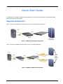
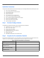
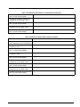
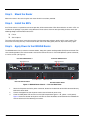
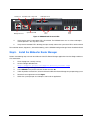
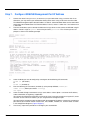
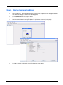
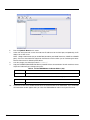
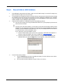
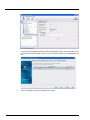
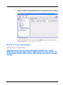
QUICK START GUIDE
[ Quick Start Guide ]
INTELLIGENT STORAGE ROUTER INSTALLATION
iSR6250
z
Purchasers of OEM products should consult with the OEM for support.
Please feel free to contact your QLogic approved reseller or QLogic
Technical Support at any phase of integration for assistance. QLogic
Technical Support can be reached by the following methods:
Web
http://support.qlogic.com
E-mail
[email protected]
The QLogic knowledge database contains troubleshooting information
for the QLogic HBAs. Access the data base from the QLogic Support
Web page, http://support.qlogic.com. Use the Support Center search
engine to look for specific troubleshooting information.
Quick Start Guide
The iSR6250 is an intelligent storage router that provides servers with iSCSI connectivity to SAN-attached Fibre
Channel-based disk or tape storage.
Suggested Configurations
Figure 1 shows the iSR6250 connecting iSCSI servers to a direct-attached storage array.
iSCSI
FC
iSCSI
iSCSI
Initiator
iSR6250
IP Switched
Network
Server
RAID Based
Fibre Channel
Storage System
Figure 1. iSR6250 in Direct Attach Configuration
Figure 2 shows the iSR6250 connecting iSCSI servers to a SAN-attached array.
Server
FC
FC SAN
iSCSI
iSCSI
iSCSI
Initiators
FC
IP Switched
Network
iSR6250
FC SAN
RAID
Based
Fibre
Channel
Storage
System
Figure 2. iSR6250 in SAN-Attach Configuration
3
Installation Instructions
This Quick Start Guide describes how to install and configure your new QLogic iSR6250 router by following these steps:
❑
Step 1. Verify the package contents.
❑
Step 2. Complete the pre-installation checklist.
❑
Step 3. Mount the router.
❑
Step 4. Install the SFPs.
❑
Step 5. Apply power to the iSR6250 router.
❑
Step 6. Install the SANsurfer® Router Manager.
❑
Step 7. Configure iSR6250 management port IP address.
❑
Step 8. Run the configuration wizard.
❑
Step 9. Present LUNs to iSCSI initiators.
❑
Step 10. Configure second blade.
Step 1. Verify the Package Contents
The iSR6250 router production package includes the following hardware components:
❑
iSR6200 router chassis with two blades installed
❑
DB9 to RJ45 cable adapter
❑
Power cable (6 foot black)
❑
Rail Mounting Kit, part number 50990-00
❑ WEEE Conformance Card
❑ Readme Notice Card
❑ China Optics and Cable SKUs Toxic Substance Table
Step 2. Complete the Pre-installation Checklist
During the initial configuration process, the system prompts you to enter information for each blade contained in the
iSR6250. Use the space provided in the following tables to record the IP addresses for each blade.
Table 1. Worksheet for Router Blade 1 (left) Parameters
Symbolic Name of the iSR6250 Blade 1
Management port IP address, subnet
mask, and gateway (if not using DHCP)
iSCSI port 1 IP address, subnet mask,
and gateway (GE-1)
IP address of the iSNS server for iSCSI
port 1 (if iSNS will be enabled)
iSCSI port 2 IP address, subnet mask,
and gateway (GE-2)
4
Table 1. Worksheet for Router Blade 1 (left) Parameters (Continued)
IP address of the iSNS server for iSCSI
port 2 (if iSNS will be enabled)
iSCSI port 3 IP address, subnet mask,
and gateway for the 10GbE-1 port
IP address of the iSNS server for iSCSI
port 3 (if iSNS will be enabled)
iSCSI port 4 IP address, subnet mask,
and gateway for the 10GbE-2 port
IP address of the iSNS server for iSCSI
port 4 (if iSNS will be enabled)
Table 2. Worksheet for Router Blade 2 (right) Parameters
Symbolic Name of the iSR6250 Blade 2
Management port IP address, subnet
mask, and gateway (if not using DHCP)
iSCSI port 1 IP address, subnet mask,
and gateway (GE-1)
IP address of the iSNS server for iSCSI
port 1 (if iSNS will be enabled)
iSCSI port 2 IP address, subnet mask,
and gateway (GE-2)
IP address of the iSNS server for iSCSI
port 2 (if iSNS will be enabled)
iSCSI port 3 IP address, subnet mask,
and gateway for the 10GbE-1 port
IP address of the iSNS server for iSCSI
port 3 (if iSNS will be enabled)
iSCSI port 4 IP address, subnet mask,
and gateway for the 10GbE-2 port
IP address of the iSNS server for iSCSI
port 4 (if iSNS will be enabled)
5
Step 3. Mount the Router
Mount the router in the rack using the rack mount kit with instructions provided.
Step 4. Install the SFPs
An SFP transceiver is required for each router port that will be connected to a Fibre Channel device or switch. SFPs are
included in the package. If you prefer using different SFP transceivers from the ones provided, purchase one of the
following QLogic recommended transceivers:
❑
Finisar
❑
JDS Uniphase
To install an SFP transceiver, insert the transceiver into the router port and press gently until it snaps in place. The
transceiver will fit only one way. If the transceiver does not install under gentle pressure, flip it over and try again.
Step 5. Apply Power to the iSR6250 Router
The iSR6250 router chassis contains two router blades, along with a power cooling module (PCM) for each blade. Each
chassis blade provides LEDs and connectors that face the front of the chassis. Each PCM provides a power connector,
as well as an LED (see Figure 3).
Front Plate iSR6250 Blade 1
Front Plate iSR6250 Blade 2
10Gb iSCSI Ports
10Gb iSCSI Ports
10GbE2
10GbE1
iSR6250
10GbE2
10GbE1
iSR6250
Intelligent Storage Router
FC1
MGMT
Intelligent Storage Router
FC2
FC1
IOIOI
MGMT
PCM Status LED
Power Connector
Back Plate PCM for Blade 2
FC2
IOIOI
PCM Status LED
Power Connector
Back Plate PCM for Blade 1
Figure 3. iSR6250 Router Chassis — Front and Back Plates
1.
Attach the AC power cord to the power connector, located on the backside of the PCM connected directly
behind the router blade.
2.
Connect the opposite end of the power cord to the wall outlet or power strip.
3.
Check the PCM power LED to make sure the PCM is operational (green = OK, yellow = no AC power).
Figure 4 shows the location of the ports and LEDs on one of the blades contained within the iSR6250 unit
that are referenced in the following instructions.
6
10Gb iSCSI Ports
RS232 Port Heartbeat LED Power LED
GE4
10GbE2
GE3
10GbE1
iSR6240
iSR6250
Intelligent Storage Router
Intelligent Storage Router
iSR6200 System
MGMT
Management Port
IOIOI
FC1
System Fault LED
FC2
FC
Ports
GE1
GE1
iSCSI
Ports
Figure 4. iSR6250 Blade Ports and LEDs
4.
Verify that the router’s input power LED is illuminated. The iSR6250 router runs its self test and begins
normal operation—this may take a minute.
5.
Verify that the heartbeat LED is blinking (once per second) and that the system fault LED is not illuminated.
For installation details, diagnostics, and troubleshooting, see the iSR6250 Intelligent Storage Router Installation Guide.
Step 6. Install the SANsurfer Router Manager
Perform the following steps to install the SANsurfer iSCSI/FC Router Manager application from the QLogic website to
a PC workstation:
1.
Close all programs currently running.
2.
Go to the QLogic download site:
http://support.qlogic.com/support/drivers_software.aspx
3.
Select the Intelligent Storage Routers icon.
4.
Select iSR6200 in the product selection window and click Go.
5.
Under the product name column, select the link to the SANsurfer Router Manager for your operating system.
6.
Read the license agreement and click Agree.
7.
Follow the system prompts to uncompress and install the application.
7
Step 7. Configure iSR6250 Management Port IP Address
1.
Connect the router’s Management Port (10/100 Ethernet) to your workstation using a switch or hub. As an
alternative, you may connect your workstation directly to the router using an Ethernet crossover cable.
The iSR6250 management port’s default IP address is 10.0.0.1 subnet 255.0.0.0. Make sure the workstation
connected to the iSR6250 router has Ethernet address 10.0.0.x, where x is other than 1 and subnet mask
is 255.0.0.0.
2.
From the workstation, open a command window and using a telnet session connect to iSR6250 using IP
address 10.0.0.1. Login as “guest” and use the password “password." This will take you to a CLI
prompt as shown in the following example.
3.
Select the blade you want to configure by entering one of the following CLI commands:
blade r1 (for blade 1)
or
blade r2 (for blade 2)
4.
Enter the following CLI commands (for blade 2) at the prompt iSR6250 (admin)#>:
admin start (Default password is "config".)
set mgmt
5.
Select the mode. QLogic recommends using a static address. Select Option 0 and enter the IP address,
subnet information, and gateway, if applicable.
You will lose the connectivity of the telnet session at this time. If you want to continue using the CLI, restart
the telnet session with the IP address you just assigned to the management port.
You now have the management port configured with the appropriate IP address. Connect the management
port cable to your Ethernet network. Connect GE1, GE2, 10GbE1, 10GbE2, FC1, and FC2 cables as shown
in the configuration diagrams (Figure 1/Figure 2).
6.
8
If necessary, repeat these procedures to configure your second blade.
Step 8. Run the Configuration Wizard
1.
Start the SANsurfer® Router Manager previously installed on the computer that will manage the iSR6250.
You should see a display as shown in the following figures.
2.
Click the Connect button on the top-left corner.
3.
Enter the IP address of the iSR6250 you want to configure.
4.
Select the router blade to be configured (Blade 1 or 2) from the system tree (in left panel).
5.
Click Yes to start the configuration wizard. The following screen appears:
9
6.
Enter the Symbolic Name for this router.
7.
Select each iSCSI port and use the wizard to enter IP addresses for the iSCSI port, and optionally, the IP
address of an iSNS server.
NOTE: QLogic recommends that you enable Flow Control for your 10GbE interfaces (10GbE1 and 10GbE2
ports). You must also enable Flow Control on the Ethernet switch to which you are connecting the router.
Ethernet flow control is defined by IEEE 802.3x.
8.
Save the changes; the default password is “config.”
9.
Copy the FC WWPN (World Wide Port Names) for both FC Ports for each blade. You will need these names
to present LUNS from your Storage subsystem.
Table 3. FC Port WWPN Names for Router Blade 1 (left)
FC 1 WWPN
FC 2 WWPN
Table 4. FC Port WWPN Names for Router Blade 2 (right)
FC 1 WWPN
FC 2 WWPN
10.
10
If you have an NTP Server, enable the NTP Server and enter the NTP Server information. This is located on
the Information tab that appears after you select the iSR6250 Router node in the System Tree view.
Step 9. Present LUNs to iSCSI Initiators
1.
If the iSR6250 is connected in the FC fabric, make sure the FC fabric zoning is set so that FC storage array
ports and router FC ports are in the same zone.
2.
Using storage array management software, create all LUNs you want to present to all iSCSI initiators through
this iSR6250. Present the LUNs from the FC storage array to the iSR6250 using WWPNs of this iSR6250.
If you are setting up a high availability configuration that uses two iSR6250s as a pair, present the LUNs
to both iSR6250s using FC WWPNs of both iSR6250s.
3.
Create the iSCSI initiator list in iSR6250 using one of the following methods:
❑
Enter the iSCSI initiator name using the Add Initiator Wizard. The system prompts you to enter the
iSCSI name of an initiator.
OR
❑
From the server with iSCSI initiators, run a discovery session for the iSCSI Port IP address of the
iSR6250. This will automatically register the iSCSI initiator names with the iSR6250. Running iSCSI
discovery session on different OS environments may vary. The example below illustrates how to
run iSCSI discovery session on Windows Server.
To run a discovery session on Windows Server:
a. Install an iSCSI initiator on your server. This can be either a dedicated iSCSI adapter or a
software initiator for Windows like the one available from www.microsoft.com.
b. Invoke the software initiator, and then specify the IP address of the iSCSI port on your
iSR6250. When you select the Targets tab, a screen appears, similar to the following:
4.
Present LUNs to iSCSI initiator:
a.
Click the Refresh button to refresh the SANsurfer display. The iSCSI initiator names should
appear on the Discovered Initiators tab.
b.
Run the LUN Presentation Wizard to assign a LUN(s) to a server(s).
11
12
c.
Launch the Presentation Wizard from the Wizards drop-down menu. This wizard allows you to
map a LUN to the iSCSI initiator on your server. The screen that allows this mapping looks like
this:
d.
Save the mappings using your management password.
e.
Refresh the SANsurfer Router Manager display. Now, when you select your iSCSI initiator on
the LHS of the display, you should be able to see the LUNs mapped to that initiator as follows:
f.
Return to the Windows Server screen and select LogOn to log on to this target. The status
should change from Inactive to Connected.
Step 10. Configure Second Blade
Repeat steps 8 and 9 for the second blade.
Congratulations! You have now successfully installed your QLogic
iSR6250 and mapped target LUNs to iSCSI initiator on your server. Your
server should see the Fibre Channel LUNs through the server’s volume
manager.
13
Troubleshooting and Technical Support
For technical support, visit the QLogic website, support.qlogic.com or send an email to [email protected].
Warranty
The QLogic iSR6250 router comes with a standard one-year QLogic warranty, or as specified by other agreements.
Check the QLogic Web site at www.qlogic.com for warranty details.
Regulatory Information (Preliminary)
The following sections contain a summary of EMC/EMI test specifications performed on the QLogic iSR6250 router to
comply with radiated emission, radiated immunity, and product safety standards.
Safety Standards
UL60950 (USA)
CSG 22.2 No. 60950 (Canada)
EN 60950 (EC)
CB Scheme-IEC 60950
Harmonics
EN 61000-3-2
Immunity
EN 55024:1998
Emission Standards
FCC Part 15B Class A (USA)
VCCI Class A ITE (Japan)
ICES-03 Issue 3 (Canada)
EN55022 Level A (EC)
CISPR 22, Class A
14
Voltage Fluctuations
EN61000-3-3
Marking
FCC Part 15
UL (United States)
TUV (United States)
cUL (Canada)
cTUV (Canada)|
TUV Europe (Germany)
VCCI
CE
GOST
MIC
BSMI/RRL
© 2009 QLogic Corporation. QLogic, the QLogic logo, SANbox, and Enterprise Fabric Suite 2007 are registered
trademarks or trademarks of QLogic Corporation. All other brands and product names are trademarks or registered
trademarks of their respective owners. Information supplied by QLogic is believed to be accurate and reliable. QLogic
Corporation assumes no responsibility for any errors in this brochure. QLogic Corporation reserves the right, without
notice, to makes changes in product design or specifications.
*SN0054545-00 A*
QLogic Corporation
949.389.6000
26650 Aliso Viejo Parkway
www.qlogic.com
Aliso Viejo, CA 92656
SN0054545-00 A