1
2007
Air-Conditioners
TECHNICAL & SERVICE MANUAL
Models
PFFY-P20VLRMM-E, PFFY-P40VLRMM-E
PFFY-P25VLRMM-E, PFFY-P50VLRMM-E
PFFY-P32VLRMM-E, PFFY-P63VLRMM-E
For use with the R410A
Safety Precautions
Read before installation and performing electrical work
Thoroughly read the following safety precautions prior to installation.
Observe these safety precautions for your safety.
This equipment may have adverse effects on the equipment on the same power supply system.
Contact the local power authority before connecting to the system.
Symbol explanations
WARNING
This symbol indicates that failure to follow the instructions exactly as stated poses the risk of serious injury or death.
CAUTION
This symbol indicates that failure to follow the instructions exactly as stated poses the risk of serious injury or damage to the unit.
Indicates an action that must be avoided.
Indicates important instructions.
Indicates a parts that requires grounding.
Indicates that caution must be taken with rotating parts. (This symbol is on the main unit label.) <Color: Yellow>
Indicates that the parts that are marked with this symbol pose a risk of electric shock. (This symbol is on the main
unit label.) <Color: Yellow>
WARNING
Carefully read the labels affixed to the main unit.
WARNING
Ask your dealer or a qualified technician to install the unit.
Do not make any modifications or alterations to the unit.
Consult your dealer for repair.
Improper installation by the user may result in water leakage, electric shock, or fire.
Improper repair may result in water leakage, electric shock,
or fire.
Properly install the unit on a surface that can withstand its
weight.
Do not touch the heat exchanger fins with bare hands.
The fins are sharp and pose a risk of cuts.
Unit installed on an unstable surface may fall and cause injury.
In the event of a refrigerant leak, thoroughly ventilate the
room.
Only use specified cables. Securely connect each cable so
that the terminals do not carry the weight of the cable.
If gaseous refrigerant leaks out and comes in contact with
an open flame, toxic gases will be generated.
Improperly connected cables may produce heat and start a
fire.
Properly install the unit according to the instructions in the
Installation Manual.
Take appropriate safety measures against wind gusts and
earthquakes to prevent the unit from toppling over.
Improper installation may result in water leakage, electric
shock, or fire.
Improper installation may cause the unit to topple over and
cause injury or damage to the unit.
Have all electrical work performed by an authorized electrician according to the local regulations and the instructions
in this manual. Use a dedicated circuit.
Insufficient power supply capacity or improper installation
of the unit may result in malfunctions of the unit, electric
shock, or fire.
HWE07170
i
GB
WARNING
Keep electrical parts away from water.
Consult your dealer or a qualified technician when moving
or reinstalling the unit.
Wet electrical parts pose a risk of electric shock, smoke, or
fire.
Improper installation may result in water leakage, electric
shock, or fire.
Securely attach the control box cover.
After completing the service work, check for a refrigerant
leak.
If the cover is not installed properly, dust or water may infiltrate and pose a risk of electric shock, smoke, or fire.
If leaked refrigerant is exposed to a heat source, such as a
fan heater, stove, or electric grill, toxic gases will be generated.
Only use the type of refrigerant that is indicated on the unit
when installing or relocating the unit.
Infiltration of any other types of refrigerant or air into the unit
may adversely affect the refrigerant cycle and may cause
the pipes to burst or explode.
Do not try to defeat the safety features of the unit.
Forced operation of the pressure switch or the temperature
switch by defeating the safety features for these devices, or
the use of accessories other than the ones that are recommended by Mitsubishi Electric may result in smoke, fire, or
explosion.
When installing the unit in a small space, take appropriate
precautions to prevent leaked refrigerant from reaching the
limiting concentration.
Leaked refrigerant gas will displace oxygen and may cause
oxygen starvation. Consult your dealer before installing the
unit.
Consult your dealer for proper disposal method.
Do not use a leak detection additive.
Precautions for handling units for use with R410A
CAUTION
Do not use the existing refrigerant piping.
Only use R410A.
A large amount of chlorine that may be contained in the residual refrigerant and refrigerator oil in the existing piping
may cause the refrigerator oil in the new unit to deteriorate.
The use of other types of refrigerant that contain chloride
may cause the refrigerator oil to deteriorate.
Use a vacuum pump with a check valve.
Use refrigerant piping materials made of phosphorus deoxidized copper. Keep the inner and outer surfaces of the
pipes clean and free of such contaminants as sulfur, oxides,
dust, dirt, shaving particles, oil, and moisture.
If a vacuum pump that is not equipped with a check valve is
used, the vacuum pump oil may flow into the refrigerant cycle and cause the refrigerator oil to deteriorate.
Contaminants in the refrigerant piping may cause the refrigerator oil to deteriorate.
Prepare tools for exclusive use with R 410A. Do not use the
following tools if they have been used with the conventional
refrigerant: gauge manifold, charging hose, gas leak detector, check valve, refrigerant charge base, vacuum gauge,
and refrigerant recovery equipment.
Store the piping materials indoors, and keep both ends of
the pipes sealed until immediately before brazing. (Keep elbows and other joints wrapped in plastic.)
If the refrigerant or the refrigerator oil that may be left on these
tools are mixed in with R410A, it may cause the refrigerator oil
in the new system to deteriorate.
Infiltration of water may cause the refrigerator oil to deteriorate.
Leak detectors for conventional refrigerants will not detect an
R410A leak because R410A is free of chlorine.
Infiltration of dust, dirt, or water into the refrigerant system
may cause the refrigerator oil to deteriorate or cause the
compressor to malfunction.
Charge the system with refrigerant in the liquid phase.
If gaseous refrigerant is drawn out of the cylinder first, the
composition of the remaining refrigerant in the cylinder will
change and become unsuitable for use.
Do not use a charging cylinder.
If a charging cylinder is used, the composition of the refrigerant
in the cylinder will change and become unsuitable for use.
Exercise special care when handling tools for use with R410A.
Infiltration of dust, dirt, or water into the refrigerant system
may cause the refrigerator oil to deteriorate.
HWE07170
ii
GB
CONTENTS
I Features
[1] Features.................................................................................................................................... 1
II Components and Functions
[1] Components and Functions...................................................................................................... 2
III Specfications
[1] Specifications............................................................................................................................ 4
1.Specfications .......................................................................................................................... 4
2.Electrical component specifications........................................................................................ 6
IV Outlines and Dimensions
[1] Outlines and Dimensions.......................................................................................................... 7
V Wiring Diagram
[1] Wiring Diagram ......................................................................................................................... 8
VI Refrigerant System Diagram
[1] Refrigerant system diagram.................................................................................................... 10
VII Troubleshooting
[1] Troubleshooting ...................................................................................................................... 11
1.Check methods..................................................................................................................... 11
2.DC fan motor (fan motor/indoor control board)..................................................................... 15
3.Address switch setting .......................................................................................................... 16
4.Voltage test points on the control board ............................................................................... 17
5.Dipswitch setting (Factory setting)........................................................................................ 18
VIII Disassembly Procedure
[1] Disassembly Procedure.......................................................................................................... 21
1.Control box ........................................................................................................................... 21
2.Thermistor (Intake air) .......................................................................................................... 22
3.Drainpan ............................................................................................................................... 23
4.Thermistor (Gas pipe) (Liquid pipe) ...................................................................................... 25
5.Fan and fan motor ................................................................................................................ 26
6.Heat exchanger .................................................................................................................... 27
HWE07170
GB
HWE07170
GB
[ I Features ]
[1] Features
I Features
Model
Cooling capacity/Heating capacity
kW
HWE07170
PFFY-P20VLRMM-E
2.2/2.5
PFFY-P25VLRMM-E
2.8/3.2
PFFY-P32VLRMM-E
3.6/4.0
PFFY-P40VLRMM-E
4.5/5.0
PFFY-P50VLRMM-E
5.6/6.3
PFFY-P63VLRMM-E
7.1/8.0
-1-
GB
[ II Components and Functions ]
[1] Components and Functions
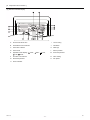
II Components and Functions
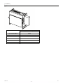
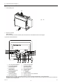
1. Indoor (Main) Unit
(A)
(A)
Air
(A)
2. Remote Controller
[PAR-21MAA]
Once the operation mode is selected, the unit will remain in the selected mode until changed.
(1) Remote Controller Buttons
1
2
[Set Temperature] Button
7
[Vane Control] Button
[Timer Menu] Button
8
[Ventilation] Button
[Monitor/Set] Button
[Operation] Button
3 [Mode] Button
9
[Check/Clear] Button
[Back] Button
10 [Test Run] Button
4 [Timer On/Off] Button
11 [Filter] Button
[Set Day] Button
[ ] Button
5 [Louver] Button
12 [ON/OFF] Button
[Operation] Button
13 Position of built-in room thermistor
6 [Fan Speed] Button
14 [Set Time] Button
Keep the remote controller out of direct sunlight to ensure accurate measurement of room temperature.
The thermistor at the lower right-hand section of the remote controller must be free from obstructions to ensure accurate measurement of room temperature.
HWE07170
-2-
GB
[ II Components and Functions ]
(2) Remote Controller Display
A
Current time/Timer time
I
Louver swing
B
Centralized control indicator
J
Ventilation
C
Timer OFF indicator
K
Filter sign
D
Timer mode
L
Sensor position
E
Operation mode display:
FAN,
HEAT
M
Room temperature
F
Function Lock indicator
N
Vane setting
G
Preset temperature
O
Fan speed
H
Power indicator
HWE07170
COOL,
DRY,
AUTO,
-3-
GB
[ III Specfications ]
[1] Specifications
III Specfications
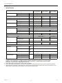
1. Specfications
Model
PFFYP20VLRMM-E
Power supply
Cooling capacity
Voltage
V
220-240
Frequency
Hz
50/60
*1
Current consumption
2.2
2.8
3.6
kW
2.5
3.2
4.0
Cooling
kW
0.04/0.04
0.04/0.04
0.04/0.04
Heating
kW
0.04/0.04
0.04/0.04
0.04/0.04
Cooling
A
0.34/0.33
0.34/0.33
0.38/0.37
Heating
A
0.34/0.33
0.34/0.33
0.38/0.37
External finish (Munsel No.)
Dimensions
Galvanized steel plate
Height
mm
Width
mm
Depth
mm
Net weight *2
kg
Heat exchanger
Fan
Motor
639
886
18.5
18.5
20
Cross fin (Aluminium fin and cupper tube)
Type
Sirocco fan x 1
Airflow rate
(Low-Mid-High)
m3/min
External static pressure
Pa
Output
kW
4.5-5.5-6.5
Sirocco fan x 2
4.5-5.5-6.5
6.5-7.5-9.0
20-40-60
0.096
0.096
0.096
PP Honeycomb fabric
Gas (Brazed connection)
mm
[in.]
ø12.7 [ø1/2]
Liquid (Brazed connection)
mm
[in.]
ø6.35 [ø1/4]
mm
[in.]
Accesory hose ø27 [1-3/32] (top end : ø20 [13/16])
Drain pipe dimensions
Operating noise
(Low-Mid-High)
1006
220
Air filter
Refrigerant pipe dimensions
PFFYP32VLRMM-E
kW
Heating capacity *1
Power consumption
PFFYP25VLRMM-E
20Pa
dB (A)
31-36-40
31-36-40
27-32-37
40Pa
34-39-42
34-39-42
30-35-41
60Pa
35-40-43
35-40-43
32-37-42
*1 Cooling/Heating capacity indicates the maximum value at operation under the following condition,
<Cooling> Indoor temperature: 27°CDB/19°CWB (81°FDB/66°FWB Outdoor temperature: 35°CDB (95°FDB)
<Heating> Indoor temperature: 20°CDB (68°FDB) Outdoor temperature: 7°CDB/6°CWB (45°FDB/43°FWB)
Pipe length: 7.5m (24-9/16ft) Height difference: 0m (0ft)
*2 The external static pressure is set to 20Pa at factory shipment.
*3 The actual capacity characteristics vary with the combination of indoor and outdoor units. See the technical information.
*4 The noise level in operation is measured at 1m apart from the front side and the bottom side of the unit in anechoic room.
(Noise meter A-scale value) Connect the duct of 1m in length to the air outlet.
HWE07170
-4-
GB
[ III Specfications ]
Model
PFFYP40VLRMM-E
Power supply
Cooling capacity
Heating capacity
Voltage
V
220-240
Frequency
Hz
50/60
*1
Current consumption
4.5
5.6
7.1
kW
5.0
6.3
8.0
Cooling
kW
0.05/0.05
0.05/0.05
0.07/0.07
Heating
kW
0.05/0.05
0.05/0.05
0.07/0.07
Cooling
A
0.43/0.42
0.48/0.47
0.59/0.58
Heating
A
0.43/0.42
0.48/0.47
0.59/0.58
External finish (Munsel No.)
Dimensions
Galvanized steel plate
Height
mm
Width
mm
Depth
mm
Net weight *2
kg
Heat exchanger
Fan
Motor
639
1006
1246
220
21
25
Type
Sirocco fan x 2
3/min
Airflow rate
(Low-Mid-High)
m
External static pressure
Pa
Output
kW
8.0-9.5-11.0
10.0-12.0-14.0
11.0-13.0-15.5
20-40-60
0.096
0.096
0.096
PP Honeycomb fabric
Gas (Brazed connection)
mm
[in.]
ø12.7 [ø1/2]
ø15.88 [ø5/8]
Liquid (Brazed connection)
mm
[in.]
ø6.35 [ø1/4]
ø9.52 [ø3/8]
Drain pipe dimensions
Operating noise
(Low-Mid-High)
27
Cross fin (Aluminium fin and cupper tube)
Air filter
Refrigerant pipe dimensions
PFFYP63VLRMM-E
kW
*1
Power consumption
PFFYP50VLRMM-E
mm
[in.]
Accesory hose ø27 [1-3/32] (top end : 20 [13/16])
dB (A)
30-36-40
32-37-41
35-40-44
40Pa
32-38-42
35-40-44
36-42-47
60Pa
35-39-44
36-41-45
38-43-48
20Pa
*1 Cooling/Heating capacity indicates the maximum value at operation under the following condition,
<Cooling> Indoor temperature: 27°CDB/19°CWB (81°FDB/66°FWB Outdoor temperature: 35°CDB (95°FDB)
<Heating> Indoor temperature: 20°CDB (68°FDB) Outdoor temperature: 7°CDB/6°CWB (45°FDB/43°FWB)
Pipe length: 7.5m (24-9/16ft) Height difference: 0m (0ft)
*2 The external static pressure is set to 20Pa at factory shipment.
*3 The actual capacity characteristics vary with the combination of indoor and outdoor units. See the technical information.
*4 The noise level in operation is measured at 1m apart from the front side and the bottom side of the unit in anechoic room.
(Noise meter A-scale value) Connect the duct of 1m in length to the air outlet.
HWE07170
-5-
GB
[ III Specfications ]
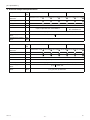
2. Electrical component specifications
Component
Symbol
Room temperature
thermistor
TH21
Liquid pipe thermistor
PFFY-P20VLRMM-E
PFFY-P25VLRMM-E
PFFY-P32VLRMM-E
Resistance 0°C/15k
, 10°C/9.6k , 20°C/6.3k , 25°C/5.4k , 30°C/4.3k , 40°C/3.0k
TH22
Resistance 0°C/15k
, 10°C/9.6k , 20°C/6.3k , 25°C/5.4k , 30°C/4.3k , 40°C/3.0k
Gas pipe thermistor
TH23
Resistance 0°C/15k
, 10°C/9.6k , 20°C/6.3k , 25°C/5.4k , 30°C/4.3k , 40°C/3.0k
Fuse
FUSE
Fan motor
250V 6.3A
8-pole, Output 96W SIC-70CW-D896-3
Linear expansion valve
LEV
Power supply terminal
block
TB2
Transmission terminal
block
TB5
TB15
Component
Symbol
Room temperature
thermistor
TH21
Liquid pipe thermistor
8-pole, Output 96W
SIC-70CW-D8114-4
12VDC Stepping motor drive port diameter ø3.2 (0~1400 pulse)
(L, N,
) 330V 30A
(1, 2), (M1, M2, S) 250V 20A
PFFY-P40VLRMM-E
PFFY-P50VLRMM-E
PFFY-P63VLRMM-E
Resistance 0°C/15k
, 10°C/9.6k , 20°C/6.3k , 25°C/5.4k , 30°C/4.3k , 40°C/3.0k
TH22
Resistance 0°C/15k
, 10°C/9.6k , 20°C/6.3k , 25°C/5.4k , 30°C/4.3k , 40°C/3.0k
Gas pipe thermistor
TH23
Resistance 0°C/15k
, 10°C/9.6k , 20°C/6.3k , 25°C/5.4k , 30°C/4.3k , 40°C/3.0k
Fuse
FUSE
Fan motor
8-pole, Output 96W SIC-70CW-D8114-4
Linear expansion valve
LEV
Power supply terminal
block
TB2
Transmission terminal
block
TB5
TB15
HWE07170
250V 6.3A
12VDC Stepping motor drive port diameter ø3.2 (0~1400 pulse)
(L, N,
) 330V 30A
(1, 2), (M1, M2, S) 250V 20A
-6-
GB
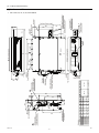
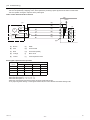
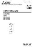
Dimensions
Model
A
PFFY-P20VLRMM-E
886
PFFY-P25VLRMM-E
PFFY-P32VLRMM-E
1006
PFFY-P40VLRMM-E
PFFY-P50VLRMM-E
1246
PFFY-P63VLRMM-E
730
970
692
932
760
1000
610
572
640
D
720
480
360
E
90
1020
780
5
7
660
G
4
F
9
98 30 8
49
220
C
84
B
Level adjusting screw
4 pcs.(attached)
1
Refrigerant piping
brazing connection (gas)
387
2- 4.7
Duct mounting hole
344
639
15.88
2-12X16
Floor mounting hole
Drain hose(accessory)
O.D.27mm(End O.D.20mm)
Sub drain pan
Drain pan
9.52
6.35
Liquid pipe
45
76
15
Air inlet
Air outlet
B(Floor mounting hole pitch)
D
C
E
2XF- 4.7
Duct mounting hole
120
G
A
88
68
2
Refrigerant piping
brazing connection (liquid)
Gas pipe
12.7
103
33
Air filter
15
2X2-12X16
Wall mounting hole
175
35
77
43
Control box
Knockout hole 27
(Power souce wiring)
Knockout hole 27
(Transmission wiring)
Terminal bed(Transmission)
Terminal bed(Power souce)
385
10
29
400
75
-7Floor mounting
hole pitch
106
300
(Wall mounting hole pitch)
HWE07170
170
B(Wall mounting hole pitch)
[ IV Outlines and Dimensions ]
IV Outlines and Dimensions
[1] Outlines and Dimensions
1. PFFY-P20, 25, 32, 40, 50, 63VLRMM-E
GB
HWE07170
CN3A
CN52
LED2
-8-
CN62
CN41
CN42
(Red)
1 2 3 4
LEV
M
1 2 3 4 5 6
CN51
CN81
(Red)
1 2 3 4 5 6 7 8
1
2
3 CN60
4
5
(Green)
6
3 (Blue)
1
CN32
I.B.
1 0 9
4 5 6
1 0 9
4 5 6
7
8
6 7 8 9 A SW5 SWC SWA
B
5
4
C
3
21 0 F E D
CN82
3
t°
1 2 3 4
1 2 3 4
TH23
1
CN4F
TH21
t°
1 2
CN20 (Red)
CN27 (Red)
CN90
SW2
SW1
CN44
SWE
OFF ON
SW4
1 2 3 4 5 6 7 8
SW3
TH22
t°
3
2
SW12
SW14
(10’s digit) (Connection No.)
1 2
7
8
SW11
(1’s digit)
3
2
1 2 3 4
SW7
A.B.
LED1
DC310~340V
Rectify circuit
CN2M
(Blue)
2 1
Fan motor
M
7 6 5 4
CNMF
U
ZNR01
1
FUSE
U
ZNR02
DSA
CND
(Black)
1
3
5
TB2
N
L
L1
TB5
M2
M1
S(SHIELD)
TB15
1
2
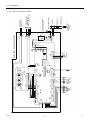
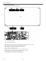
INSIDE SECTION OF CONTROL BOX
POWER SUPPLY
~220,230,240V
50,60Hz
BREAKER (16A)
FUSE (16A)
PULL BOX
TO NEXT INDOOR UNIT
only PFFY-P63VLRMM-E
TO OUTDOOR UNIT
BC CONTROLLER
REMOTE CONTROLLER
TO MA REMOTE
CONTROLLER
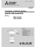
[ V Wiring Diagram ]
V Wiring Diagram
[1] Wiring Diagram
1. PFFY-P20,25,32,40,50,63VLRMM-E
GB
[ V Wiring Diagram ]
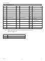
Table.1 SYMBOL EXPLANATION
SYMBOL
NAME
SYMBOL
NAME
SYMBOL
NAME
I.B.
Indoor control board
CN32
Connector (Remote switch)
SW4
(I.B.)
Switch (model setting)
A.B.
Address board
CN41
Connector (HA terminal-A)
SWE
(I.B.)
Connector (emergency operation)
TB2
Power supply terminal block
CN51
Connector (Centralized control)
SW1
(A.B.)
Switch (function setting)
TB5
Transmission terminal block
CN52
Connector (Remote display)
SW5
(A.B.)
Switch (function setting)
TB15
Transmission terminal block
CN90
Connector (Wireless)
SW7
(A.B.)
Switch (model setting)
FUSE
Fuse AC 250V 6.3A
TH21
Thermistor (inlet air)
SW11
(A.B.)
Switch (For setting the 1's digit
in the address)
ZNR01,
02
Varistor
TH22
Thermistor (liquid pipe)
SW12
(A.B.)
Switch (For setting the 10's
digit in the address)
DSA
Arrester
TH23
Thermistor (gas pipe)
SW14
(A.B.)
Switch (connection No.setting)
AC reactor (Power factor improvement)
SW2
(I.B.)
Switch (capacity code setting)
SWA
(A.B.)
Switch (static pressure setting)
Connector (Damper)
SW3
(I.B.)
Switch (function setting)
SWC
(A.B.)
Switch (static pressure setting)
L1
CN27
LEV
Note
Electronic linear expan.valve
1 Wiring to TB2, TB5, and TB15 indicated by the double-dashed lines is on-site work.
2
terminal block,
connector.
Table.2 OPERATION OF LED FOR INDOOR CIRCUIT BOARD SERVICE
SYMBOL
LED operation under normal state
LED1
At applying main power source -> Lighting
LED2
At receiving MA transmission power source -> Lighting
HWE07170
-9-
GB
[ VI Refrigerant System Diagram ]
[1] Refrigerant system diagram
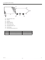
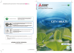
VI Refrigerant System Diagram
(A)
(B)
(G)
(D)
(C)
(H)
(F)
(E)
(I)
(A)
Gas pipe thermistor TH23
(B)
Gas pipe
(C)
Liquid pipe
(D)
Brazed connections
(E)
Strainer (#100 mesh)
(F)
Linear expansion valve
(G)
Liquid pipe thermistor TH22
(H)
Heat exchanger
(I)
Room temperature thermistor TH21
(E)
Capacity
PFFY-P20, 25, 32, 40, 50VLRMM-E
PFFY-P63VLRMM-E
Gas pipe
ø12.7 [1/2]
ø15.88 [5/8]
Liquid pipe
ø6.35 [1/4]
ø9.52 [3/8]
HWE07170
- 10 -
GB
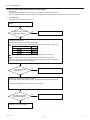
[ VII Troubleshooting ]
[1] Troubleshooting
VII Troubleshooting
1. Check methods
1. Component and check points
(1) Thermistor
Room temperature thermistor (TH21)
Liquid pipe thermistor (TH22)
Gas pipe thermistor (TH23)
Disconnect the connector and measure the resistance between terminals with a tester.
(Ambient temperature 10°C - 30°C)
Normal
4.3k
Abnormal
- 9.6k
Open or short
(Refer to the thermistor characteristic graph below.)
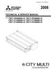
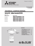
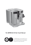
1) Thermistor characteristic graph
Low-temperature thermistor
Room temperature thermistor (TH21)
Liquid pipe thermistor (TH22)
Gas pipe thermistor (TH23)
50
Thermistor R0 = 15 k
3%
Multiplier of B = 3480 k
2%
Rt = 15 exp { 3480(
1 )}
273
15k
9.6k
6.3k
5.2k
4.3k
3.0k
30
(B)
0°C
10°C
20°C
25°C
30°C
40°C
1
273+t
40
20
(A) Temperature
(°C)
(B) Resistance
(k )
10
0
-20
-10
0
10
20
30
40
50
(A)
(2) Fan motor (CNMF)
Refer to the page on "DC fan motor (fan motor/indoor control board)."
(3) Linear expansion valve
Disconnect the connector, and measure the resistance between terminals with a tester.
Refer to the next page for details.
(F)
(E)
(D)
LEV
(C)
(B)
(A)
Normal
CN60
1
2
3
4
5
6
1-5
White-Red
150 k
(A)
Brown
(D)
Orange
(B)
Red
(E)
Yellow
(C)
Blue
(F)
White
HWE07170
2-6
Yellow-Brown
Abnormal
3-5
Orange-Red
4-6
Blue-Brown
Open or short
10%
- 11 -
GB
[ VII Troubleshooting ]
1) Summary of linear expansion valve (LEV) operation
The LEV is operated by a stepping motor, which operates by receiving a pulse signal from the indoor control board.
The LEV position changes in response to the pulse signal.
Indoor control board and LEV connection
(G)
12VDC
(A)
6
(C)
(B)
5
(A)
(C)
4
(E)
(D)
3
(E)
2
(F)
1
(J)
4
M
6
5
2
1
(F) (B) (D)
3
(I)
(H)
(A)
Brown
(F)
White
(B)
Red
(G)
Control board
(C)
Blue
(H)
Connection (CN60)
(D)
Orange
(I)
Drive circuit
(E)
Yellow
(J)
Linear expansion valve
Pulse signal output and valve operation
Phase
number
1
2
Output pulse
ø1
ON
OFF
OFF
ON
ø2
ON
ON
OFF
OFF
ø3
OFF
ON
ON
OFF
ø4
OFF
OFF
ON
ON
3
4
The output pulse changes in the following order:
When the valve closes 1 -> 2 -> 3 -> 4 -> 1
When the valve opens 4 -> 3 -> 2 -> 1 -> 4
When the valve position remains the same, all output signals will be OFF.
If any output signal is missing or if the signal remains ON, the motor vibrates and makes clicking noise.
HWE07170
- 12 -
GB
[ VII Troubleshooting ]
2) LEV operation
(f)
(a)
(a)
Close
(b)
Open
(c)
Fully open valve (2000 pulses)
(d)
No. of pulses
(e)
Extra tightning (0 - 200 pulse)
(f)
Valve opening degree
(b)
(c)
(d)
(e)
When the power is turned on, a pulse signal of 2200 pulses is output (valve closure signal), to bring the valve to position A.
When the valve is operating normally, it is free of vibration noise. If the valve locks or when it goes from point E to A in the
figure, it makes louder noise than would be heard when there is an open phase.
Check for abnormal sound/vibration by placing the metal tip of a screwdriver against the valve and the handle side against
your ear.
3) Troubleshooting
Symptom
Checking Criteria
Remedy
Circuit failure on
Disconnect the connectors on the control board, and connect LEDs to test the cirthe microcomputer cuit as shown below.
6
5
Replace the indoor control
board if driving
circuit failure is
detected.
4
3
2
1k
LED
1
Pulse signals are output for 10 seconds when the main power is turned on. If there
are LEDs that do not light up at all or remain lit after the pulses are turned off, there
is a problem with the driving circuit.
Locked LEV
The motor will idle and make small clicking noise if it is run while the LEV is locked.
If this clicking noise is heard both when the valve is fully closed and while it is being
opened, it indicates a problem.
Replace the LEV.
Disconnected or
shorted LEV motor
coils
easure the resistance between the coils with a tester (red-white, red-orange,
brown-yellow, brown-blue). The normal range of resistance is 150
10%
Replace the LEV.
HWE07170
- 13 -
GB
[ VII Troubleshooting ]
Symptom
Checking Criteria
Remedy
Valve closure failure (leaky valve)
To check the LEV on the indoor unit, check the indoor unit liquid pipe temperature
that appears on the operation monitor on the outdoor unit's multi control board while
operating the indoor unit in question in the FAN mode and the other indoor units in
the cooling mode.
Replace the LEV
if the amount of
leakage is great.
(A)
Termistor (TH21)
(A)
LEV
Normally, the LEV is fully closed while the unit is in the FAN mode. If the valve is
leaky, liquid pipe thermistor reading will be lower than normal. If it is significantly
lower than the inlet temperature on the remote controller, valve closure failure is
suspected. If the amount of leakage is insignificant, replacement of LEV is unnecessary unless it is causing a problem.
Misconnections of Perform a visual check for disconnected connectors.
connectors or con- Perform a visual check of lead wire color.
tact failure
HWE07170
- 14 -
Disconnect the
connectors on
the control board
and perform a
continuity test.
GB
[ VII Troubleshooting ]
2. DC fan motor (fan motor/indoor control board)
1. CAUTION
A high voltage is applied to the connector for connection to the fan motor (CNMF).
Do not unplug the connector CNMF with the unit energized to avoid damage to the indoor control board and fan motor.
2. Troubleshooting
Symptom: Indoor unit fan does not run.
Check fan motor connector contact
(CNMF).
Is the fan motor connector
(CNMF) fully inserted?
No
Fix the connection.
Yes
Check the power supply.
Measure the voltage at the indoor control board.
310 - 340VDC (same with the voltage between fan connector 1 (+) and 4(-))
Power supply voltage
VDC
15VDC (same with the voltage between fan connector 5 (+) and 4(-))
1 - 6.5VDC (same with the voltage between fan connector 6 (+) and 4(-))
[Values for Vsp are the values that are measured with the fan motor in operation.
Vsp is 0V when the fan motor is stopped.]
Is the voltage within the
normal range?
No
Replace the indoor control board.
Yes
Check the fan motor position thermistor signal.
Get the motor to make a full rotation or more, and measure the voltage at the test point
VFG.
(same with the voltage between fan connector 7 (+) and 4(-))
Are 0VDC and 15VDC
displayed alternately?
No
Replace the motor.
Yes
Replace the indoor control board.
HWE07170
- 15 -
GB
[ VII Troubleshooting ]
3. Address switch setting
Make sure that power to the unit is turned off.
(A)
(B)
ON
OFF
(A)
Indoor unit control board
(B)
Factory setting (all models)
ON
OFF
1. When using an ME remote controller, set the address with the rotary switches (SW11, SW12).
Address setting is not required when the unit remote controller is used.
On-site address setting is required for the indoor units to run.
2. Address settings vary in different systems.
Refer to the section on address setting in the outdoor unit installation manual.
3. Address is set with a combination of SW12 (10's digit) and SW11 (1's digit).
To set the address to "3," set SW12 to "0" and SW11 to "3."
To set the address to "25," set SW 12 to "2" and SW 11 to "5."
HWE07170
- 16 -
GB
[ VII Troubleshooting ]
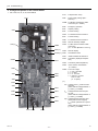
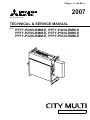
4. Voltage test points on the control board
1. PFFY-P20, 25, 32, 40, 50, 63VLRMM-E
Fuse
CND
С25(*1)
CNMF
C951(*1)
Fuse
Fuse(AC 250V 6.3A)
CND
Power supply voltage (220 240VAC)
CN2M
For M-NET transmission cable
connection (24 - 30VDC)
SWE
Emergency operation
SW2
Capacity setting
SW4
Function setting
CN42
For address board connection
SW3
Function setting
CN81
For address board connection
CN32
Remote start/stop adapter
CN3A
For MA remote controller cable
connection
(10 - 13 VDC (Between 1 and 3.))
CN52
Remote display
PC941(*1) CN51
CN2M
SW2
CN3C
CN20
SW4
JAMA standard HA terminal A
CN44
Thermistor (liquid/gas temperature)
CN20
Thermistor (Inlet temperature)
CN3C
Indoor-outdoor transmission
(0 - 24VDC)
CNMF Fan motor output
1 - 4: 310 - 340 VDC
5 - 4: 15 VDC
6 - 4: 0 - 6.5 VDC
7 - 4: Stop 0 or 15 VDC
Run 7.5 VDC
(0 - 15 pulse)
(*1)
CN42
SW3
CN44
CN81
CN41
CN32
CN51
CN52
LED2 CN3A
HWE07170
CN41
LED1
SWE
Centralized control
VFG Voltage on the (-) side of PC941
and C25
(Same with the voltage between 7
(+) and 4 (-) of CNMF)
VCC Voltage between the C25 pins
15 VDC
(Same with the voltage between 5
(+) and 4 (-) of CNMF)
Vsp Voltage between the C951 pins
0VDC (with the fan stopped)
1 - 6.5VDC (with the fan in operation)
(Same with the voltage between 6
(+) and 4 (-) of CNMF)
CN60
- 17 -
GB
[ VII Troubleshooting ]
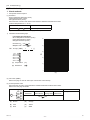
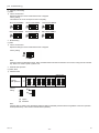
5. Dipswitch setting (Factory setting)
1. Function setting
(1) SW1
Switch position
Function
Switch setting
ON
OFF
1
Active Thermistor (Intake air thermistor)
Built-in thermistor on the remote
controller
Indoor unit
2
Filter clogging detection
Available
Unavailable
3
Filter life
2500 hr
100 hr
4
Outdoor air intake
Enabled
Disabled
5
Remote display
Thermo-ON signal
Fan output
6
Humidifier operation
During heating mode
During heating operation
7
Fan speed
Low
Very low
8
Fan speed at heating Thermo-OFF Preset fan speed
Follows the setting of SW1-7
9
Auto restart after power failure
Enabled
Disabled
10
Power start/stop
Enabled
Disabled
1) Adress board
Factory setting
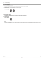
(2) SW3
Switch position
Function
Switch setting
ON
1
Unit type
Cooling only
OFF
Heat pump
2
-
-
-
3
-
-
-
4
-
-
-
5
-
-
-
6
-
-
-
7
-
-
-
8
Heating 4-deg up
Disabled
Enabled
1) Indoor control board
Dipswitch settings must be made while the unit is stopped.
Factory setting
HWE07170
PFFY-P20,25VLRMM-E
PFFY-P32,40,50,63VLRMM-E
- 18 -
GB
[ VII Troubleshooting ]
2. Capacity code setting
(1) SW2
1) Indoor control board
Dipswitch settings must be made while the unit is stopped.
Factory setting
The switches are set to correspond to the unit capacity.
PFFY-P20VLRMM-E
PFFY-P25VLRMM-E
PFFY-P32VLRMM-E
PFFY-P40VLRMM-E
PFFY-P50VLRMM-E
PFFY-P63VLRMM-E
3. Model setting
(1) SW4
1) Indoor control board
Dipswitch settings must be made while the unit is stopped.
Factory setting
Note:
Changes made to the dipswitches SW1, SW2, and SW3 will become effective when the unit comes to a stop (remote controller
off). There is no need to power cycle the unit.
4. External static pressure
(1) SWA, SWC
1) Address board
SWA, SWC
20Pa
40Pa
60Pa
Adderess board
2
3
2
1
1
SWA SWC
2
3
2
1
1
SWA SWC
<At delivery>
External
1-3
static pressure 1 - 2
Factory
setting
3
2
1
SWA
2
2
3
3
2
2
1
1
1
1
SWA SWC SWA SWC
(A)
(B)
2
1
SWC
(A) Option
(B) Standard
Note:
Changes that are made to the dipswitches SWA and SWC immediately become effective regardless of the unit's operation
status (RUN/STOP) or the remote controller status (ON/OFF).
HWE07170
- 19 -
GB
[ VII Troubleshooting ]
5. 1's and 10's digits
(1) SW11, SW12 (Rotary switch)
The use of a network remote controller (PAR-F27MEA) requires address setting.
1) Address board
Address settings must be made while the unit is stopped.
Factory setting
6. Connection No. setting
(1) SW14 (Rotary switch)
This switch is used when the unit connected to an R2 series of outdoor unit.
1) Address board
Factory setting
Note:
Changes to the dipswitches SW11, SW12 and SW14 must be made while the unit is stopped and the remote controller is OFF.
HWE07170
- 20 -
GB
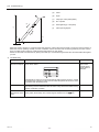
[ VIII Disassembly Procedure ]
[1] Disassembly Procedure
VIII Disassembly Procedure
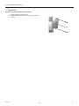
1. Control box
Exercise caution when removing heavy parts.
1. Removing the control box cover
(1) Remove the fixing screws (two) on the cover (A) to remove it.
(A)
HWE07170
- 21 -
GB
[ VIII Disassembly Procedure ]
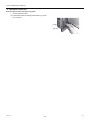
2. Thermistor (Intake air)
Exercise caution when removing heavy parts.
1. Removing the thermistor
(1) Pull out the thermistor holder (B) and thermistor (C) under
the control box.
(C)
(B)
HWE07170
- 22 -
GB
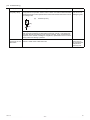
[ VIII Disassembly Procedure ]
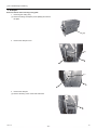
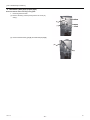
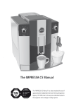
3. Drainpan
Exercise caution when removing heavy parts.
1. Removing the casing ass'y
(1) Remove the fixing screws(nine) of the plate(D) and remove
the plate.
(D)
2. Remove the drainpan cover
(E)
(F)
3. Remove the drainpan
(1) Remove the fixing screw of the both side frame.
HWE07170
- 23 -
GB
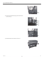
[ VIII Disassembly Procedure ]
(2) Remove the magnet plate (G),(H),(I) of the both frame,remove the tube (J).
(G)
(H)
(J)
(I)
(3) Slide the drainpan in the direction of the arrow 1.
HWE07170
- 24 -
GB
[ VIII Disassembly Procedure ]
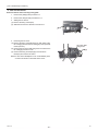
4. Thermistor (Gas pipe) (Liquid pipe)
Exercise caution when removing heavy parts.
1. Removing the thermistor
(1) Remove the fixing screws (three),remove the cover (K)
and (L).
(K)
(L)
(2) Remove the thermistor (gas)(M) and thermistor(liquid)(N).
(M)
(N)
HWE07170
- 25 -
GB
[ VIII Disassembly Procedure ]
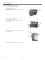
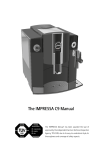
5. Fan and fan motor
Exercise caution when removing heavy parts.
1. Remove the plate(D) with procedure 3-1.
2. Remove the drainpan with procedure 3-2,3.
3. Sliding the fan section
(1) Remove the fixing screws(two).
(2) Slide the fan section in direction of the arrow 2.
4. Removing the fan motor
(1) Remove the fixing screws(three)(a) on both sides of the
fan casing(O) and turn the fan casing(O) in the upward direction (arrow 3).
(2) Remove the fan motor shaft fixing screw and remove the
fan casing(O) and sirocco fan.
(3) Remove the fixing screws(two)(b) of the motor fixtures(two) and remove the motor.
fan motor shaft
fixing screw
(O)
Notice:In case of the Model(PFFY-P32 - 63VLRMM-E) stick
out the motor shafts on both side of the motor.
(b)
(a)
HWE07170
- 26 -
GB
[ VIII Disassembly Procedure ]
6. Heat exchanger
Exercise caution when removing heavy parts.
1. Remove the plate(D) with procedure 3-1.
2. Removng the air diffuser ass'y
(1) Remove the fixing screws(eight) of the air diffuser ass'y(P)
and remove it.
(P)
3. Remove the cover1,2 with procedure 4-1.
4. Removing the Heat exchanger
(1) Remove the fixing screws(four) and remove the heat exchanger support.
(2) Remove the fixing screws(two) and remove the heat exchanger cover(Q).
(Q)
(3) Remove the heat exchanger, moving from side to side.
HWE07170
- 27 -
GB
Nov. 2007 HWE07170
Printed in Japan
New publication, effective Nov. 2007
Specifications subject to change without notice