1
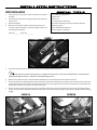
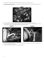
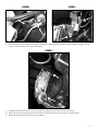
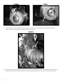
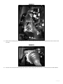
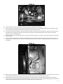
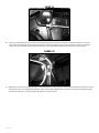
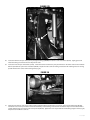
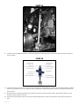
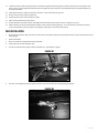
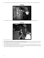
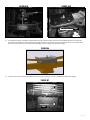
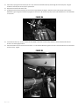
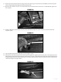
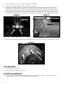
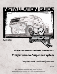
Part#: 021653
4.5” & 6.5” High Clearance Suspension System
Chevy/GM 2500/3500 HD Pickup 2WD/4WD | 2011-2015
Rev. 120914
491 W. Garfield Ave., Coldwater, MI 49036 . Phone: 517-279-2135
Web/live chat: www.bds-suspension.com . E-mail: [email protected]
Read And Understand All Instructions
And Warnings Prior To Installation Of
System And Operation Of Vehicle.
Your truck is about to be fitted with the best suspension system on the market today. That means you will be driving the
baddest looking truck in the neighborhood, and you’ll have the warranty to ensure that it stays that way for years to come.
Thank you for choosing BDS Suspension!
BEFORE YOU START
BDS Suspension Co. recommends this system be installed by a professional
technician. In addition to these instructions, professional knowledge of
disassembly/ reassembly procedures and post installation checks must be
known.
FOR YOUR SAFETY
Certain BDS Suspension products are intended to improve off-road
performance. Modifying your vehicle for off-road use may result in the
vehicle handling differently than a factory equipped vehicle. Extreme care
must be used to prevent loss of control or vehicle rollover. Failure to drive
your modified vehicle safely may result in serious injury or death. BDS
Suspension Co. does not recommend the combined use of suspension lifts,
body lifts, or other lifting devices. You should never operate your modified
vehicle under the influence of alcohol or drugs. Always drive your modified
vehicle at reduced speeds to ensure your ability to control your vehicle under
all driving conditions. Always wear your seat belt.
BEFORE INSTALLATION
• Special literature required: OE Service Manual for model/year of vehicle.
Refer to manual for proper disassembly/reassembly procedures of OE and
related components.
• Adhere to recommendations when replacement fasteners, retainers and
keepers are called out in the OE manual.
• Larger rim and tire combinations may increase leverage on suspension,
steering, and related components. When selecting combinations larger
than OE, consider the additional stress you could be inducing on the OE
and related components.
• Post suspension system vehicles may experience drive line vibrations.
Angles may require tuning, slider on shaft may require replacement, shafts
may need to be lengthened or trued, and U-joints may need to be replaced.
• Secure and properly block vehicle prior to installation of BDS Suspension
components. Always wear safety glasses when using power tools.
• If installation is to be performed without a hoist, BDS Suspension Co.
recommends rear alterations first.
• Due to payload options and initial ride height variances, the amount of lift
is a base figure. Final ride height dimensions may vary in accordance to
original vehicle attitude. Always measure the attitude prior to beginning
installation.
2 | 021653
6.5” Kit:
37 x 12.50 on 17” x 9” w/ 4-1/2 to 4-5/8” Backspacing
37 x 12.50 on 18” x 9” w/ 4-1/2 to 4-5/8” Backspacing
37 x 12.50 on 20” x 9” w/ 5 to 6” Backspacing
Larger than 20”, use 20” wheel specs
Stock 20” x 8.5” wheel will fit with a max tire size of 35 x 12.50.
A wider tire will cause clearance issues with the steering
knuckle and a taller tire will interfere with the sway bar. Stock
17” and 18” wheels will not fit back on the vehicle once this
suspension system is installed.
4.5” Kit: Same as above, except with maximum 35x12.50 size
BEFORE YOU DRIVE
Check all fasteners for proper torque. Check to ensure for adequate clearance
between all rotating, mobile, fixed, and heated members. Verify clearance
between exhaust and brake lines, fuel lines, fuel tank, floor boards and wiring
harness. Check steering gear for clearance. Test and inspect brake system.
Perform steering sweep to ensure front brake hoses have adequate slack and
do not contact any rotating, mobile or heated members. Inspect rear brake
hoses at full extension for adequate slack. Failure to perform hose check/
replacement may result in component failure. Longer replacement hoses, if
needed can be purchased from a local parts supplier.
Perform head light check and adjustment.
Re-torque all fasteners after 500 miles. Always inspect fasteners and
components during routine servicing.
011218 - 4.5” rear 2” kit - non overload
021650-021651
Part #
Qty
Description
Part #
Qty
2fb18
2
2" x 18mm pin blocks
02360
1
Steering Knuckle - Drv
343251350QB
4
3/4" x 3-1/4" x 13-1/2" square black
02361
1
Steering Knuckle - Pass
B1085
1
Bag Kit
Description
011217 - 4.5” rear 2” kit - overload
021654 - 6.5” kit only
Part #
Qty
Description
Part #
2fb18
2
2" x 18mm pin blocks
02364B
1
Torsion Bar Bracket -DRV
Qty
Description
343251550QB
4
3/4" x 3-1/4" x 15-1/2" square black
02365B
1
Torsion Bar Bracket - PASS
B1085
1
Bag Kit
02367
2
T-Bar Brkt Spacer - Front
02368
2
T-Bar Brkt Spacer - Rear (Grooved)
587
1
Bolt Pack - Torsion Bar Brkts
021454 - 4.5” kit only
Part #
Qty
Description
02766
1
Torsion Bar Brkt - DS
2
1"-8 x 6" bolt
1" USS flat washer
02767
1
Torsion Bar Brkt - PS
4
02367
2
Hex Eliminator - Frt
2
1"-8 nylock nut
02368
2
Hex Eliminator - Rear (Grooved)
2
14mm-2.00 x 70mm bolt
Bolt Pack
4
14mm flat washer
2
14mm-2.00 prevailing torque nut
021652
2
9/16" SAE flat washer
Part #
2
6mm-1.00 hex nut
587
1
Qty
Description
02362B
1
Front Crossmember
02373B
1
Crossmember Brace
22533D
1
Front Brake Line - DRV
22533P
1
Front Brake Line - PASS
013318/011317
5188
2
Brake Line Clip
Part #
590
1
Bolt Pack - Front Brake Lines
3FBB18
6
Wire Clamp
343251350QB
4
3/4x3-1/4x13-1/2 Square U-Bolt (011318 only)
4
1/4"-20 x 3/4" bolt
343251550QB
5
3/4x3-1/4x15-1/2 Square U-Bolt (011317 only)
4
1/4" lock washer
B1225G8
2
12mm-1.75x25mm socket head bolt
1/4" x 1/2" self-tapping bolt
N34FLG-B
8
3/4” Serrated Flange Nut
2
Qty
2
Description
3” Block
021653 | 3
021653
Part #
021509/021508
Qty
Description
Part #
Qty
Description
911109
2
Sway Bar Link
5FB18
2
Rear 5" Block w/Wing
02363B
1
Rear Crossmember
02415
2
U-Bolt Plate
02369B
1
Differential Bracket - Drv
344001812RB
4
3/4x4x18-1/2 Round U-Bolt (021508 only)
02370B
1
Differential Bracket - Center
344001600RB
4
3/4x4x18-1/2 Round U-Bolt (021509 only)
1
E-Brake Bracket
1
Rear Brake Line Extension
02371B
1
Differential Bracket - Pass
SBCE
02372B
1
Differential Skid Plate
SBCA
01556
2
Upper Shock Mount
B12X114
4
1/2"-13 x 1-1/4" bolt
W12S
8
1/2" SAE flat washer
N12PT
4
1/2"-13 prevailing torque nut
02129
2
Sway Bar Link Bracket
45313
2
0.625 x 0.109 x 1.375 Sleeve
S10076
4
Stem Washer
342701
2
Loctite
01596
1
Steering Stop - Drv
01597
1
Steering Stop - Pass
70
1
Sleeve - Center Diff. Brkt
3523BK
2
Bushing - Center Diff. Brkt
SB58BK
2
Sway Bar Link Bushing
SB26BK
4
Stem Bushing
585
1
Bolt Pack - Lower Control Arms
2
18mm-2.50 x 120mm bolt
2
18mm-2.50 x 140mm bolt
4
18mm-2.50 prevailing torque nut
8
3/4" SAE flat washer clear zinc
586
582
4 | 021653
1
Bolt Pack - Main Assembly
6
1/2"-13 x 1-1/4" bolt
2
1/2"-13 x 1-1/2" bolt
2
1/2"-13 x 3-1/2" bolt
4
1/2"-13 prevailing torque nut
12
1/2" SAE flat washer
4
7/16" USS flat washer
2
12mm-1.75 x 40mm bolt
1
9/16"-12 x 4" bolt
1
9/16"-12 prevailing torque nut
2
9/16" SAE flat washer
4
10mm-1.50 x 40mm bolt
4
10mm flat washer
1
Bolt pack - Sway Bar Links
2
7/16"-14 nylock nut - clear zinc
2
3/8"-16 x 2-1/2" bolt grade 8 - yellow zinc
4
3/8" SAE washer yellow zinc
2
3/8"-16 Prevailing torque nut - yellow zinc
2
5/8" SAE washer clear zinc
2
5/8"-11 nylock nut clear zinc
SBTE
1
6mm-1.00 x 95mm Threaded Rod
N34FLG-B
8
3/4” Serrated Flange Nut
588
1
Bolt Pack - Rear
1
3/8"-16 x 1" bolt
2
3/8" SAE flat washer
1
3/8"-16 nylock nut
1
1/4"-20 x 1" bolt
2
1/4" USS flat washer
1
1/4"-20 prevailing torque nut
1
6mm-1.00 coupler nut
2
6mm-1.00 hex nut
121650
Part #
Qty
02380B
1
Description
Front Skid Plate
1.
Do not install this
suspension system in
conjunction with any type
of torsion bar lift keys.
2.
Disassembly/assembly of the factory torsion bar
system requires the use of a special unloading tool.
The GM specified tool # is CH48809.
3.
Some minor trim will be required with certain wheel/
tire combination. This is normal with most aftermarket
tire/wheel fitment on Chevy/GM trucks. Trimming will
normally included the bottom edge of the inner fender
shrouds and/or lower corner of front bumper valance.
As a rule of thumb, deeper backspacing and shorter/
narrower tires will reduce/eliminate trimming required.
Further trimming tips are included at the end of this
instruction sheet.
Front Installation
1.
Park the vehicle on a flat, clean surface and block the rear wheels
for safety.
2.
Raise the front of the vehicle and support with jack stands under
the frame rails.
3.
Remove the wheels.
4.
Measure and record the length of the exposed thread on the
torsion bar adjuster bolts (Fig 1). Record the lengths here for use
later during the installation
1-1/2” (38mm) socket/wrench
34mm socket
T30 Torx bit
1-1/16” (27mm) socket/wrench
Torsion Bar Unloading tool (see Pre-Installation Note #2)
Reciprocating Saw
4” Cut-off Wheel/Tool (optional)
Pair of Large (8-10”) C-Clamps
DRV Side:_________ PASS Side:__________
FIGURE 1
5.
Unload the torsion bars but do not remove. Remove and save adjuster bolt/retainer block.
Torsion bars are under extreme pressure. A proper torsion bar tool is necessary to unload the bars. A tool designed
specifically for GM torsion bars is required see troubleshooting note #2.
6.
Mark the unloaded torsion bars to indicate DRV side and PASS side. Also mark the bars to indicate front versus rear.
7.
Remove the torsion bar adjuster plate by pushing the torsion bar forward to allow the plate to drop free. On some vehicles this will require
using a hammer/punch or air hammer. Access the end of the torsion bar through the hole in the back of the torsion bar crossmember and
drive forward. Leave the torsion bars in the lower control arms. 8.
Remove the two bolts that attach the torsion bar crossmember to the frame rails (Fig 2A). Remove the torsion bar crossmember from the
vehicle. Save bolts and crossmember. On diesel models, disconnect the wire on the passenger’s side of the crossmember before removing
(Fig 2B)
figure 2A
FIGURE 2B
021653 | 5
9.
Remove the torsion bars by pulling them rearward out of the lower control arms. Set the torsion bars aside.
10. Remove the front plastic splash guard, save splash guard bolts. If equipped, remove the four bolts mounting the factory belly pan to the
frame (Fig 3) These will not be reused.
FIGURE 3
11. Disconnect the sway bar end links from the sway bar and the lower control arms (Fig 4A). Discard the link assemblies.
12. Disconnect the tie rod ends from the steering knuckles (Fig 4A). Remove the tie rod end nuts and save. Strike the knuckle near the tie rod
end to dislodge the tie rod end taper (Fig 4B). Remove the tie rod ends from the knuckles.
figure 4A
figure 4B
13. Disconnect the ABS brake wire from the connector at the frame (Fig 5) Remove the wire from the plastic retainers on the frame and brake
line bracket on the steering knuckle (Fig 6).
14. Disconnect the rubber brake line bracket from the steering knuckle (Fig 6).
6 | 021653
figure 5
figure 6
15. Remove the two bolts mounting the brake caliper assembly to the steering knuckle and hang the caliper out of the way (Fig 7). Do not
hang the caliper by the brake hose. Save mounting bolts.
figure 7
16. Carefully remove the hub dust cover. Save cover (Fig 8). Tip: Carefully work the cover loose with a small chisel.
17. Remove the rotor retaining bolt using a T30 torx bit (Fig 9). Remove the brake rotor and set aside. Save retaining bolt.
18. Remove the CV axle nut and washer (Fig 9). Save hardware.
021653 | 7
figure 8
figure 9
19. Locate and remove the four hub bearing assembly bolts (Fig 10). The bolts are accessed from the back side of the steering knuckle. Remove the hub bearing assembly and dust shield from the steering knuckle.
figure 10
HIDDEN
20. Remove the upper and lower ball joint nuts (Fig 11). Reinstall the nuts a couple of turns by hand. Strike the knuckle near the ball joints to
release the taper. Remove the nuts and remove the steering knuckle from the vehicle. Save nuts. Take care not to strike the ball joint.
8 | 021653
figure 11
21. Remove the CV axle flange bolts at the differential (Fig 12). There are 8 bolts per side. Remove the CV shafts from the vehicle and set aside.
Save bolts.
figure 12
22. Disconnect the shocks from the frame (Fig 13A) and lower control arm (Fig 13B). Remove shocks. Save the lower shock mount hardware.
021653 | 9
figure 13A
figure 13B
23. Remove the front and rear lower control arm bolts and remove the control arms from the vehicle (FIg 14) Save the control arms and
mounting hardware.
figure 14
24. There are two factory bump stops per side. Remove the front rubber bumpstop from the frame mounts on each side. They can be
removed with a pair of channel-lock pliers.
25. Make an alignment mark on the front driveshaft and front differential input yoke. Remove the four bolts/clamps from the yoke and remove
the front driveshaft from the differential (Fig 15). Save the driveshaft hardware.
figure 15
10 | 021653
26. Remove the four bolts mounting the rear crossmember to the rear lower control arm pockets (Fig 16). Remove the crossmember from the
vehicle. The crossmember and hardware will not be reused.
figure 16
27. Disconnect the electrical connector from the front differential actuator (Fig 17A) Remove the wire from the three plastic wire retainers
along the top of the differential.
28. Disconnect the axle breather tube from the top of the driver’s side of the differential (Fig 17B).
figure 17A
figure 17B
29. Loosen but do not remove all of the front differential mounting bolts/nuts. There are two nuts on the passenger’s side (Fig 18A) and three
bolts on the driver’s side (Fig 18B - two mount from the bottom up and one from the top down). Remove the rear-most bolt mounting
from the top.
021653 | 11
FigURE 18B
FigURE 18A
ACCESS FROM TOP
30. Support the front differential with an appropriate jack. Remove the differential mounting hardware and lower the differential from the
vehicle and set aside. Save hardware.
31. The lower rear driver’s side control arm pocket must be trimmed to provide clearance for the front differential. On the front face measure
from the center of the control arm mounting hole inward 1-1/4” and mark. Fig. 19A On the back face measure from the center of the
control arm mounting hole inward 2-1/2” and mark. Fig. 19B Make vertical cut lines at the marks on the front and back faces. Along the
top, connect the front and back cut lines with a diagonal cut. Fig. 19C
figure 19A
figure 19B
1¼"
2½"
12 | 021653
figure 19C
32. Using a reciprocating saw (recommended), hack saw or cut-off wheel, cut the pocket along cut lines. Remove any burrs or rough edges and
paint any bare metal to prevent corrosion.
33. Install the provided large bushings (3523) and 0.875” OD x 2.620” long sleeve (70) into the eye of the new center differential bracket (02370)
(Fig 21).
figure 21
34. Locate the 4 housing bolts to be removed. Remove the four bolts, place the bracket in position and fasten with new 10mm x 40mm bolt
and washers (BP 586). The bracket gusset will be toward the bottom of the differential (Fig 22). Use Loctite on the bolt threads and torque
to 40 ft-lbs.
figure 22
021653 | 13
35. Locate the new passenger’s side differential bracket (02371). Bracket has a single center gusset. Install the bracket on the existing studs
on the passenger’s side factory bracket. Fasten with the original nuts and washers. When installed the open side of the bracket will face
inward and the bracket will taper down as it goes to the rear (Fig 23). Torque nuts to 65 ft-lbs.
figure 23
36. Locate the new driver’s side differential bracket (02369). Bracket has two center gussets. Install the bracket to the 2 front original
differential mounting holes with the provided 12mm-1.75 x 40mm bolts and 1/2” SAE washers (BP 586), applying Loctite to the threads
before installation. When installed the open side of the bracket will face inward and the bracket will taper down as it goes to the rear (Fig
24). Torque bolts to 65 ft-lbs.
figure 24
37. Using an appropriate jack, raise the differential up into the vehicle. Align the differential mounting holes to the new driver’s and
passenger’s side differential brackets. Fasten to the driver’s side mount with 1/2” x 3-1/2” bolts, nuts and 1/2” SAE flat washers (BP 586). Fasten the passenger’s side 1/2” x 1-1/2” bolts, nuts and heavy 1/2” (large OD)washers (BP 586). Leave hardware loose.
38. Locate the new rear crossmember (02363). Install the crossmember in the rear lower control arm pockets with the factory control arm
bolts/nuts. Run the bolts from rear to front. The center differential bracket will fit into the mount tabs on the crossmember. Fasten the
differential mount to the crossmember with a 9/16” x 4” bolt, nut and 9/16” SAE washers (BP 586). Leave hardware loose. (Fig 25)
figure 25
14 | 021653
39. With the differential and rear crossmember installed, tighten all the differential mount hardware. Torque the (4) 1/2” bolts to 65 ft-lbs and
(1) 9/16” bolt to 95 ft-lbs.
40. Reconnect the front driveshaft to the front differential with the factory clamps and bolts. Torque hardware to 25 ft-lbs.
41. Reconnect the front differential actuator wire. Reattach the wire harness to the housing. Use the provided zip ties where needed. Pull
down on the differential breather hose to gain slack and reconnect to the top of the differential.
42. Locate the new front crossmember. Install the crossmember in the front lower control arm pockets and fasten with the original control arm
bolts/nuts. Run the bolt from front to rear. Leave hardware loose.
43. Locate the new provided aluminum torsion bar bracket spacers. There are 2 pairs of spacer. One pair has a groove cut in the flange which
mount in the back side of the torsion bar hex holes in the factory lower control arms. The other pair mount in the front position (Fig 26A/B).
figure 26A
figure 26B
44. Locate the new torsion bar brackets (02364/02365 - 6.5” Kit or 02766/02767 4.5” Kit). They are driver’s and passenger’s side specific. Slide
the bracket onto the appropriate arm and fasten through the aluminum spacers with the provided 1” x 6” bolts, nuts and washers (BP 587). Run the bolts from back to front (Fig 27A). The brackets will also align with the factory shock mount. Place a provided 9/16” SAE washer (BP
587)between the front bracket tab and the factory shock mount (Fig 27B). Fasten with the factory lower shock bolt/nut. Leave all hardware
loose.
45. With both new torsion bar bracket installed on the factory control arms, install the control arms in the crossmembers. Fasten the control
arms with the provided 18mm x 120mm (front) and 18mm x 140mm bolts, nuts and 3/4” SAE flat washers (BP 585). Run the front bolts
front-to-rear and the rear bolts rear-to-front. (Fig 28) Leave hardware loose. These bolts will be torque with the weight of the vehicle on the
suspension.
figure 27A
figure 27B
WASHER
021653 | 15
figure 28
46. Locate the new differential skid plate (02372). Position the skid plate so that it aligns to holes with the welded nuts on the bottom driver’s
side of the rear crossmember (Fig 30). Fasten the skid plate with 1/2” x 1-1/4” bolts and 1/2” SAE washers (BP 586). Snug hardware so the
front of the skid plate sets up near the bottom of the front crossmember.
47. Locate the new crossmember support brace (02373). The brace is formed to clear the differential actuator when installed. Position the
support brace so it sets properly against the bottom of the front and rear crossmembers and aligned to the mounting holes. Fasten the
tube to the rear crossmember with a 1/2” x 1-1/4” bolt and 1/2” SAE washer (BP 586). Again, snug hardware so the brace sets up near the
bottom of the front crossmember (Fig 30).
48. Locate the new front “BDS” skid plate/splash guard (02380). Loosely attach the skid plate to the original splash guard mounting holes
on the upper frame crossmember using the original splash guard bolts. (Fig 29A) Position the skid plate up to the bottom of the front
crossmember “sandwiching” the support brace and differential skid plate. Fasten the front skid plate, differential skid plate and support
tube to the front crossmember with 1/2” x 1-1/4” bolts and 1/2” SAE washers (BP 586) in the welded nuts in the crossmember (Fig 29B). Apply Loctite to the bolt threads and torque to 55 ft-lbs.
49. With the front hardware tight, remove the rear bolts one at a time and apply Loctite to the threads. Reinstall and torque to 55 ft-lbs. Torque
the front factory splash guard bolts to 25 ft-lbs.
50. After all the skid plate hardware is tight, go back and torque the 4 factory lower control arm pocket bolts (mounting the new
crossmembers) to 250 ft-lbs.
51. Locate the new steering knuckles and identify the driver’s and passenger’s side. Install the appropriate knuckle on the lower control arm
and fasten with the original lower ball joint nut. Swing the knuckle up and attach to the upper ball joint with the original nut. Torque the
upper ball joint nut to 37 ft-lbs and the lower ball joint nut to 74 ft-lbs (Fig 30).
figure 29A
figure 29B
16 | 021653
figure 30
52. Locate the hub o-ring in the factory steering knuckle hub bores. Carefully remove the o-rings (Fig 31) and install into the new steering
knuckles.
figure 31
53. Locate the factory driver’s and passenger’s brake dust shields. They need to be modified to provided adequate brake caliper clearance. Make a cut line by following the straight edge on the caliper side of the shield all the way to the bottom edge of the shield. (Fig 32) Cut the
shield along the line.
021653 | 17
figure 32
54. Install the hub assembly and dust shield into the appropriate steering knuckle. The ABS line will run out the top of the hub and behind the
dust shield. (Fig 33) Fasten the hub to the knuckle with the factory bolts. Apply Loctite to the threads and torque the bolts to 125 ft-lbs.
figure 33
55. Run the ABS line around the front of the steering knuckle and up to the wire connector on the frame. Reconnect the wire and reattach it to
the original place on the frame.
56. Locate the factory torsion bars and install them into the new torsion bar brackets. Be sure to install the bars on the correct side of the
vehicle and in the correct orientation (front vs rear).
57. Reinstall the torsion bar crossmember in the frame with the original mounting bolt. Torque bolts to 90 ft-lbs. Slide the torsion bars back
to the crossmember and install the factory torsion adjuster keys. The torsion bars will be loaded at the end of the installation. On diesel
models, reconnect the factory wiring that was disconnected during disassembly (Fig 2B).
58. Locate the factory CV axle shafts. Install the CV axle into the hub assembly (Fig 34) and then onto the differential output flange. Align the
differential flange holes and fasten with the factory bolts. Apply Loctite to the threads and torque to 40 ft-lbs.
18 | 021653
figure 34
59. Install the original CV axle nut and washer and torque to 155 ft-lbs. Reinstall the hub dust cap.
60. Install the brake rotor on the hub by aligning the tapered retainer bolt hole in the rotor with the threaded hole in the hub flange. Fasten
the rotor to the hub with the original retainer bolt and tighten securely with a T30 torx bit.
61. Locate the factory brake line junction at the frame where the hardline and rubber line meet. (Fig 5) Using a 13mm line wrench disconnect
the hardline from the rubber line. Remove the retaining clip and pull the line from the frame bracket. Place a bucket, etc under the
hardline to catch any brake fluid drips.
62. With the brake lines free, install the brake calipers on the knuckles with the original bolts. Apply Loctite to the bolt threads and torque the
bolts to 125 ft-lbs.
63. Locate the new provided stainless steel brake lines (22533D/P). The lines are driver’s and passenger’s side specific. The caliper end has a
offset jog. When install the hardline at the caliper will offset towards the inside of the vehicle. Identify the appropriate lines. (Fig 35 - Pass
Side Shown)
figure 35
64. Remove the factory brake line from the caliper. Be sure to remove the factory crush washers as well. Place a new provided crush washer on
each face of the new brake line and install on the caliper with the factory banjo bolt. Torque the bolt to 20 ft-lbs.
65. Run the new brake line up to the factory frame mount bracket. Feed the end of the line through the bracket and fasten to the factory
hardline. Using a 13mm line wrench on the hard line fitting and 11/16” wrench on the new line, tighten the fitting securely. Secure the line
to the factory bracket with the original brake line clip or the provided new one (5188). (Fig 36)
021653 | 19
figure 36
66. There are two threaded holes near the top of the steering knuckle neck on the back side. Using a provided wire clamp, 1/4” x 3/4” bolt
and 1/4” lock washer (BP 590) loosely fasten the brake line to the lower threaded hole on the steering knuckle. Using the same fastener
combination, attach the ABS line to the upper threaded hole. The hardware will be tightened once the line slack is set. (Fig 37A).
figure 37A
67. On the front side of the steering knuckle there is a small threaded hole. Using a third wire clamp, fasten the ABS wire to the front face of the
knuckle with a 1/4” x 1/2” self-tapping bolt (BP 590). Tighen securely. (Fig 37B) Adjust the slack in the two other lines, rotating the steering
knuckle back and forth as a check, and tighen the upper two clamps to 10 ft-lbs.
20 | 021653
figure 37B
68. Locate the new front sway bar links (911109), hourglass bushings (SB58RB) and 0.625” x 1.375” steel sleeves (45313). Lightly grease and
install the bushings and sleeves into the sway bar link ends.
69. Locate the 2 new sway bar link brackets (02129). Install the bracket into the factory sway bar link holes in the lower control arms and fasten
with the provided 5/8” nylock nuts and washers (BP582). Torque the nuts to 90 ft-lbs making sure that the link mounting holes are running
parallel with the lower control arm mounting bolts. (Fig 38)
figure 38
70. Install the new sway bar links into the new brackets and fasten with the provided 3/8” x 2-1/2” bolts, nuts and 3/8” SAE washers (BP 582). Leave bolts loose. Install a provided 7/16” washer followed by a stem bushing. Install the link end into the sway bar end and fasten with a
second stem bushing, 7/16” washer and 7/16” nylock nut (BP 582). Tighten the 7/16” nut just until the stem bushings begin to swell. (Fig 39)
Torque the 3/8” hardware to 30 ft-lbs.
021653 | 21
figure 39
71. Locate the new provided BDS front shocks. Follow the diagrams for assembling the upper shock ends. (Fig 40) A small amount of grease
will aid assembly.
figure 40
72. Install the front shocks in the vehicle. Fasten the lower mount with the provided 14mm x 70mm bolt, nut and washers (BP587). Fasten the
upper bar pin bracket with 1/2” x 1-1/4” bolts, nuts and 1/2” SAE washers. Torque the upper bolts to 60 ft-lbs. Torque the new lower shock
bolt to 90 ft-lbs.
73. With the front shocks installed, torque the front shock bolt at the new torsion bar bracket to 90 ft-lbs. Apply Loctite to the main 1” bolt
threads and torque the bolt to 200 ft-lbs.
74. Attach the tie rod ends to the knuckles. The tie rod end with mount from the top down. Fasten with the original nuts and torque to 37
ft-lbs.
22 | 021653
75. Load the torsion bars with the appropriate tool. Reinstall the adjuster bolt/retaining plate assembly. Reset the torsion bar adjuster bolt
position to the original height measurement taken at the beginning of the installation. This adjustment will be checked/changed at the
end of the installation.
76. Install the front wheels. Torque the lug nuts to 140 ft-lbs. Lower the vehicle to the ground.
77. Bounce the front end to settle the suspension.
78. Torque the lower control arm bolts (4) to 250 ft-lbs.
79. Check all front hardware for proper torque.
80. Properly bleed the entire brake system. Top off fluid. Check all brake lines for proper clearances. Adjust as necessary.
81. Check tire/wheel clearance with the fenders/bumper as well as with the steering knuckle. It is not uncommon to trim the lower plastic
valance of the bumper and inner fender shroud slightly to add proper tire clearance while turning.
Rear Installation
1.
Block the front wheels for safety. Raise the rear of the vehicle and support with jack stands under the frame rails, just ahead of the front leaf
spring hangers.
2.
Remove the wheels.
3.
Raise rear of vehicle and support frame with jackstands.
4.
Support the rear axle with a hydraulic jack.
5.
Disconnect brake line from inside the driver’s side frame rail. Save hardware. (Fig R1)
figure R1
6.
Disconnect the emergency brake line from the junction block in front of the rear leaf spring hanger. (Fig R2)
figure R2
021653 | 23
7.
Disconnect the E-brake cable bracket from the frame near the rear jounce bumper. Save hardware, it will be reinstalled later. (Fig R3)
figure R3
8.
Push the ABS wire clips from the metal tabs just inside of the leaf springs. Remove the plastic clips from the ABS wire.(Fig R4)
figure R4
9.
Remove the rear shocks. Save hardware.
10. With the axle well supported, remove the passenger’s side u-bolts and lower u-bolt plate. Loosen, but do not remove the u-bolt hardware
on the driver’s side. This will allow the axle to move more easily and aid in installation.
11. 2” Rear Box Kit Only: Lower the axle and install the new 2” block with new curved u-bolts. Snug but do not tighten at this time. Repeat 2”
block installation on opposite side. Skip ahead to step #16.
12. 3” & 5” Rear Block Kit Only: Clamp the leaf spring pack with c-clamps and remove the upper u-bolt retaining plate by removing the center
pin nut. Reinstall and tighten the center pin nut to 35 ft-lbs. Loosely place the new u-bolt plate (02374) on top of the leaf spring. The plate
will use the rear most hole to go around the center pin nut. (Fig R5a, R5b)
24 | 021653
Figure R5a
figure R5b
FRONT
13. 3” & 5” Overload options: The Models equipped with overload leafs will need the separation block modified. Trim the anti-rotation tabs
from the front side of block on both the inside and outside of the block. Use extreme care near the fuel tank, do not use any method that
will create sparks if the block is not removed when modified. A sawzall is highly recommended. (Fig R6)
Figure R6
14. Lower the axle to allow the lift block (5FB18) to be installed. The leaf spring pin will go in the REAR hole of the block. (Fig R7)
figure R7
PIN
FRONT
021653 | 25
15. Attach axle to springs with new u-bolts (5/8” x 4” x 16”). Run the u-bolts from bottom up and through the new u-bolt plate. Snug the
hardware at this time, but do not torque to specification.
16. Repeat block installation for driver’s side.
17. Carefully form the brake bracket at the axle to point up at approximately 45 degrees. Bend the e-brake cable bracket at the top of the
differential to give enough slack at full droop. (Fig R8) 2” rear box kit - skip ahead to step #25, e-brake cable modification is not needed with
2” rear box kit
figure R8
18. 3” & 5” Rear block kit only: ake line relocation bracket (SBCA) to the frame rail with factory hardware. Use the hole that will allow the
bracket to be offset slightly forward.
19. Attach the brake line to the relocation bracket with ¼” x 1-1/4” hardware (BP 588). Tighten to 20 ft-lbs. Form the brake lines to clear the fuel
tank if necessary. (Fig R9)
figure R9
26 | 021653
20. Remove the e-brake cable from the factory hanger in front of the leaf spring. Place the relocation bracket (SBCE) so the cable will go thru
the slot and the bottom formed edge lines up with the frame bracket.
21. Mark hole center and drill out to 3/8”~7/16”. Attach E-brake relocation bracket to frame rail with 3/8” x 1” hardware (BP 588). Tighten to 30
ft-lbs. (Fig R10)
figure R10
Step 19
Step 22 - Check Clearance
22. Thread on a M6 jam nut and the coupler nut to the e-brake cable (BP 588). Adjust the coupler nut depth to have half of the threads
engaged. (Fig R11)
figure R11
23. Attach the M6 threaded extension (SBTE) with jam nut and tighten securely.
24. Reattach the e-brake cable to the junction block with the factory adjuster nut. Tighten until the e-brake cable is at the appropriate tension.
Test the e-brake to make sure it functions properly. Adjust tension if necessary. (Fig R12) Check the e-brake cable clearance where it passes
through the original hole it was removed from in step 18. If necessary, drill this hole out to 5/8” to provide more clearance and prevent the
cable from catching the hole edge. (Fig R10)
figure R12
021653 | 27
25. Reinstall the E-brake cable bracket near the jounce bumper with factory hardware.
26. Check all cables for adequate slack at full droop, make adjustments if necessary.
27. Install new rear shocks with ¾” SAE washers on each side of the bushings. (Fig R13). Tighten hardware to 110 ft-lbs. 3” & 5” rear box kit
SHOCK NOTE: If installing BDS 5500 series (white) shocks, the passenger’s side axle bump stop pad will need to be trimmed for proper
clearance of the larger-than-factory shock body as well as relocation of the e-brake cable bracket. Measuring from the bottom inside corner
of the pad (near the shock mount), make cut marks 1” up from the bottom and 1-1/4” outward from the inside edge. Also measure back
from the front face 3/8”. (Fig R14) Cut the square section out with a cut-off tool. Paint exposed metal. The e-brake bracket will need to be
relocated up 3/4”. Transfer the holes up 3/4” and drill to 7/32”. Reattach the bracket with new 1/4” x 1” self threading bolt (bolt pack # 588).
FigURE R13
FigURE R14
MOVE HOLES UP 3/4"
28. Remove clips on wheels (Fig R15). Reinstall wheels and lower vehicle to the ground. Torque u-bolts to 125 ft-lbs. Torque lug nuts to 140 ft‑lbs.
figure R15
Post-Installation
1.
Check all hardware for proper torque.
2.
Reconnect the positive and negative battery cables.
Set Front Suspension Height
3.
It is very common for the particular vehicle model to have widely varying starting suspension heights. In order to give a more precise
suspension height setting we have provided a Z-height reference. Refer to Figure A
28 | 021653
FigURE A
FigURE B
Y
X
4.
Roll the vehicle forward and back to settle the front suspension. With the vehicle on flat, level ground measure the distance from the floor
to the center of the front lower control arm bolt. This is distance ‘Y’.
Record here:____________
5.
Measure from the floor up to the lowest point on the new steering knuckle, near the ball joint. (Fig B). This is distance ‘X’.
Record here:____________
6.
6.5” Kit only: To determine the Z-height use the following equation: Y-X=Z. For the intended 6.5” of lift the value for Z should be
approximately 7-1/4”. If your value for ‘Z’ is less then 7-1/4” the torsion bars need to be adjusted up (tightened). If your value for ‘Z’ is more
then 7-1/4” the torsion bars need to be adjusted down (loosened). The ‘Z’ height should not exceed 7-1/4”. However, this system can be run
at a lower ride height down to a minimum of 5” of lift. At 5” the ‘Z’ height is 5-3/4”. The ‘Z’ height should not be run below 5-3/4” with the
6.5” system.
7.
4.5” Kit only: To determine the Z-height use the following equation: Y-X=Z. For the intended 4.5” of lift the value for Z should be
approximately 5-1/4”. If your value for ‘Z’ is less then 5-1/4” the torsion bars need to be adjusted up (tightened). If your value for ‘Z’ is more
then 5-1/4” the torsion bars need to be adjusted down (loosened). The ‘Z’ height should not exceed 6”. However, this system can be run
at a lower ride height down to a minimum of 4” of lift. At 4” the ‘Z’ height is 4-3/4”. The ‘Z’ height should not be run below 4-3/4” with the
4.5” system. The jounce bumpers will ride on the torsion bar relocation bracket, this is the same setup as factory and is part of the factory
spring rate.
Final Check
8.
The vehicle will need a complete front end alignment.
9.
Check all hardware after 500 miles.
10. Adjust headlights.
Thank you for choosing BDS Suspension.
For questions, technical support and warranty issues relating to this BDS Suspension product, please contact your distributor/installer
before contacting BDS Suspension directly.
021653 | 29