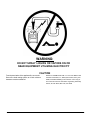
1
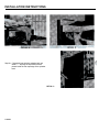
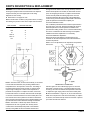
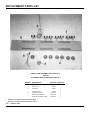
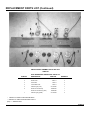
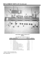
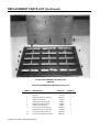
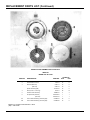
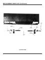
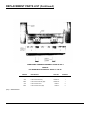
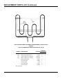
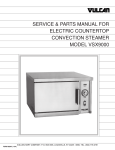
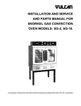
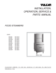
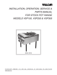
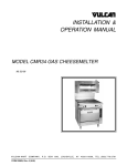
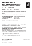
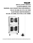
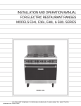
OPERATING, INSTALLATION,
SERVICE & PARTS
MANUAL FOR
ELECTRIC RESTAURANT RANGES
MODELS: E-36 SERIES & E-60 SERIES
VULCAN-HART COMPANY, P.O. BOX 696, LOUISVILLE, KY 40201-0696, TEL. (502) 778-2791
FORM 112674 (9-93)
IMPORTANT
OPERATING, INSTALLATION AND SERVICE PERSONNEL
Operating information for this equipment has been prepared for use by qualified and/or authorized operating
personnel.
All installation and service on this equipment is to be performed by qualified, certified, licensed and/or
authorized installation or service personnel, with the exception of any marked with a ? in front of the part
number.
Service may be obtained by contacting the Factory Service Department, Factory Representative or Local
Service Agency.
DEFINITIONS
QUALIFIED AND/OR AUTHORIZED OPERATING PERSONNEL
Qualified or authorized operating personnel are those who have carefully read the information in this manual
and are familiar with the equipment's functions or have had previous experience with the operation of the
equipment covered in this manual.
QUALIFIED INSTALLATION PERSONNEL
Qualified installation personnel are individuals, a firm, corporation or company which either in person or
through a representative are engaged in, and are responsible for:
1. The installation of gas piping from the outlet side of the gas meter, or the service regulator when the meter
is not provided, and the connection and installation of the gas appliance. Qualified installation personnel
must be experienced in such work, be familiar with all precautions required, and have complied with all
requirements of state or local authorities having jurisdiction. Reference in the United States of America National Fuel Gas code ANSI Z223.1 (Latest Edition) In Canada-Canadian Standard CAN1-B149.1 NAT.
GAS (Latest Edition) or CAN1-B149.2 PROPANE (Latest Edition).
2. The installation of electrical wiring from the electric meter, main control box or service outlet to the electric
appliance. Qualified installation personnel must be experienced in such work, be familiar with all
precautions required, and have complied with all requirements of state or local authorities having
jurisdiction. Reference: In the United States of America-National Electrical Code ANSI NFPA No. 70
(Latest Edition). In Canada-Canadian Electrical Code Part 1 CSA-C22.1 (Latest Edition).
QUALIFIED SERVICE PERSONNEL
Qualified service personnel are those who are familiar with Vulcan equipment who have been endorsed by
the Vulcan-Hart Corporation. All authorized service personnel are required to be equipped with a complete set
of service parts manuals and stock a minimum amount of parts for Vulcan equipment.
SHIPPING DAMAGE CLAIM PROCEDURE
For your protection, please note that equipment in this shipment was carefully inspected and packed by
skilled personnel before leaving the factory. The transportation company assumes full responsibility for safe
delivery upon acceptance of this shipment.
If shipment arrives damaged:
1. VISIBLE LOSS OR DAMAGE — Be certain this is noted on freight bill or express receipt and signed by
person making delivery.
2. FILE CLAIM FOR DAMAGES IMMEDIATELY — Regardless of extent of damage.
3. CONCEALED LOSS OR DAMAGE — If damage is unnoticed until merchandise is unpacked, notify
transportation company or carrier immediately, and file "concealed damage" claim with them. This should
be done within (15) days of date of delivery is made to you. Be sure to retain container for inspection.
We cannot assume responsibility for damage or loss incurred in transit We will, however, be glad to furnish
you with necessary documents to support your claim.
PLEASE RETAI N THIS MANUAL FOR FUTURE REFERENCE
IMPORTANT NOTES FOR ALL VULCAN APPLIANCES
1. These units are produced with the best possible workmanship and material. Proper installation is vital if best performance and
appearance are to be achieved. Installer must follow the installation instructions carefully.
2. Information on the construction and installation of ventilating hoods may be obtained from the "Standard for the installation of
equipment for the removal of smoke and grease laden vapors from commercial cooking equipment," NFPA No. 96 (latest edition)
available from the National Fire Protection Association, Battery March Park, Quincy MA 02269.
3. For an appliance equipped with a flexible electric supply cord, the cord is equipped with a three prong (grounding) plug. This
grounding plug is for your protection against shock hazard and should be plugged directly into a properly grounded three prong
receptacle. Do not cut or remove the grounding prong from this plug. If the appliance is not equipped with a grounding plug, and
electric supply is needed, ground the appliance by using the ground lug provided (refer to the wiring diagram).
(FOR GAS APPLIANCES ONLY)
4. Do not obstruct the air flow into and around the appliance. This air flow is necessary for proper combustion of gases and for
ventilation of the appliance. Provisions for ventilation of incoming air supply for the equipment in the room must be in accordance
with National Fuel Gas Code ANSI Z223.1 (latest edition).
5. Do not obstruct the flow of flue gases from the flue duct (when so equipped) located on the rear (or sides) of the appliance. It is
recommended that the flue gases be ventilated to the outside of the building through a ventilation system installed by qualified
personnel.
6. For an appliance equipped with casters, (1) the installation shall be made with a connector that complies with the Standard for
Connectors for Movable Gas Appliances, ANSI Z21.69 (latest edition), and Addenda, Z21.69a (latest edition), and a quickdisconnect device that complies with the Standard for Quick-Disconnect Devices for Use With Gas Fuel, ANSI Z21.41 (latest
edition), and Addenda, Z21.41a (latest edition) and Z21.41b (latest edition), and (2) adequate means must be provided to limit the
movement of the appliance without depending on the connector and the quick-disconnect device or its associated piping to limit
the appliance movement.
If disconnection of the restraint is necessary, reconnect this restraint after the appliance has been returned to its originally
installed position
7. The appliance and its individual shutoff valve must be disconnected from the gas supply piping system during any pressure
testing of that system at test pressures in excess of 1/2 psig (3.45 k Pa).
8. The appliance must be isolated from the gas supply system by closing its individual manual shutoff valve dunng any pressure
testing of the gas supply system at test pressures equal to or less than 1/2 psig (3.45 k Pa).
CAUTIONS
FOR YOUR SAFETY
DO NOT STORE OR USE GASOLINE OR OTHER FLAMMABLE VAPORS AND LIQUIDS
IN THE VICINITY OF THIS EQUIPMENT OR ANY OTHER APPLIANCE.
1. KEEP THE APPLIANCE FREE AND CLEAR FROM ALL COMBUSTIBLE SUBSTANCES.
2. IN THE EVENT A GAS ODOR IS DETECTED, SHUT UNIT(S) DOWN AT THE MAIN
SHUTOFF VALVE AND CONTACT THE LOCAL GAS COMPANY OR GAS SUPPLIER FOR
SERVICE.
3. POST IN A PROMINENT LOCATION, INSTRUCTIONS TO BE FOLLOWED IN THE EVENT
THE SMELL OF GAS IS DETECTED. THIS INFORMATION MAY BE OBTAINED FROM A
LOCAL GAS SUPPLIER.
WARNING:
DO NOT SPRAY LIQUIDS OR VAPORS ON OR
NEAR EQUIPMENT UTILIZING ELECTRICITY
CAUTION
From the termination of the appliance flue vent to the
filters of the hood venting system, an 18 inch minimum
clearance must be maintained.
Reference: ANSI/NFPA 96-1984 4-1.2.2.2. of the National Fire
Protection Association, Inc., Batterymarch Park, Quincy, MA
02269, and National Building Code 1976 Sec. 1015.7b (2) of
The American Insurance Association. Engineering and Safety
Service, 85 John Street, New York, NY 10038.
112674-4
ELECTRIC RESTAURANT RANGES
Your Vulcan Electric Range is produced with the best
possible workmanship and materials. Proper usage and
maintenance will result in many years of satisfactory
performance.
INDEX
The manufacturer suggests that you thoroughly read
this entire manual and carefully follow all of the
instructions provided. Retain this manual for future use.
DESCRIPTION
DEFINITIONS OF PERSONNEL (Operating, Installation, Service & Parts)
SHIPPING DAMAGE CLAIM PROCEDURE
WARNING & CAUTION NOTATIONS
INDEX
INSTALLATION INSTRUCTIONS
OPERATION INSTRUCTIONS
PAGE
(Inside Front Cover)
112674-3 thru 4
115726-5
112674-6 thru 7
112674-8 thru 10
TROUBLE SHOOTING
112674-11 thru 13
PARTS DESCRIPTION & REPLACEMENT
112674-14 thru 29
REVISION SHEET
112674-5
115726-30
INSTALLATION INSTRUCTIONS
GENERAL INSTALLATION NOTES:
The area around units should be kept free and clear of all
combustible materials. All units should be positioned for
easy accessibility of servicing. All required wiring diagrams are located in the back section of this manual.
Vulcan's Restaurant Ranges are U.L listed under File No.
E75870 and are for use on electric service of the characteristics specified on the name plate.
Units designed for 208 or 240 volt AC will operate
satisfactorily within the voltage range of 197 to 219 and
228 to 252 VAC respectively. Units designed for 220/380
or 240/415 VAC require voltage supplies with grounded
neutral (3-phase, 4 wire or 1-phase, 3 wire supply).
Units wired for 3-phase service may be changed to 1phase or vice versa, by simply relocating two wires on
the terminal block as shown on the wiring diagram and
schematic decal which is attached to the unit.
The Vulcan equipment is produced with the best possible
workmanship and material. Proper installation is vital if
best performance and appearance is to be achieved.
Please follow these instructions carefully:
1. Remove crating with care. Remove all woodworking,
packing material and accessories.
2. Unit has been factory equipped and electrically connected for use with the specific electric supply
indicated on the rating plate, check the electric supply
available. If the two voltages (supply and equipment)
do not agree, contact your dealer or Vulcan-Hart
immediately without proceeding to the next step.
3. Uncrate High Shelf, Backguards, and/or VB-73 Broiler.
In E-36-B and E-60-B series, slide the legs of the
broiler inside the channels provided in the back of the
range (in E-60 series, the broiler is mounted between
the center and the right hand channel), until the (2)
holes on each side line up. Use the bolts and nuts
provided. In a similar way mount the backguard to the
left side of the broiler.
INSTALL THE HIGH SHELF — The high shelf for this
range is shipped knocked down and is included in the
range crate.
The splasher back and heat shield are bolted together
and shipped attached to the rear of the range.
The hardware required to assemble the shelf is packed
in the oven.
Step 1 Remove the splasher back and heat shield
from the rear of the range.
Step 2 Remove the heat shield from the splasher
back by removing two sheet metal screws.
Step 3 With top cooking plates in their normal position assemble splasher back to range per
detail A and fasten in place with 1/4-20
screws and nuts.
Step 4 Place shelf in position on splasher as illustrated in detail B and fasten with 1/4-20
screws and nuts provided.
Step 5 Assemble heat shield to splasher back per
detail C — top edge of heat shield must be
placed inside the rear top flange of the
splasher back.
4.
5.
6.
7.
CAUTION
It is essential that the heat shield in the back of the
high shelf be installed in such a way that the bent
section at the bottom be inward, touching the rear wall
of the range, thereby allowing the stack action of the
double wall back splasher to draw air through the area
below the top surface units.
On ranges equiped with VB-73 Broiler, bring the leads
A1, A2, B1, and B2 (on 220/380 or 240/415 volt
models, the leads are X, Y, N) which are connected to
the broiler down and through the burner box to the
switch panel compartment. Connect them to the
appropriate circuit breaker or terminal block as shown
on the wiring diagram.
Position the range in its final location. Bring conduit
containing the proper supply wire (select the size and
type of the field wire in accordance with national
Electric Code suitable for carrying the equipment's
rated amps and voltage. Use field wires suitable for
75°C on units carrying more than 80 amps), to the
range through the knockout of the left side.
Connect the supply leads to the field terminal block
and the green, grounding lead to the labeled ground
lug.
Using a carpenter level, placed on top of the range,
adjust the feet of the bottom of each leg so that the
equipment is level from front to back and side to side.
Turn the main power and range's breakers to on. The
unit is now ready for operation. To place unit in operation, simply turn thermostat dial to desired setting
(See Operating Instructions).
112674-6
INSTALLATION INSTRUCTIONS
Step No. 5 Assemble heat shield to splasher back per
detail C — top edge of heat shield must be
placed inside the rear top flange of the splasher
back.
DETAIL C
112674-7
OPERATING INSTRUCTIONS
THEORY OF OPERATION
These highly versatile medium duty electric ranges have
been engineered and built to give years of satisfactory
use. Vulcan Electric Restaurant Ranges are designed for
nursing homes, plant cafeterias, churches, schools, restaurants, etc., normally preparing foods in quantities of 50
servings or less. Range is NOT designed for heavy duty
application.
1. SURFACE UNITS: Solid surface units are French type
cast iron 9 1/2" in diameter with clamped on sheath
type 2000 W. heating elements. Most efficient when
used with utensils having a maximum inside diameter
of 10" or a minimum inside diameter of 9". Stock pots
of 9, 12 and 16 qt. capacities are recommended for
bulk cooking. Heavy Duty hi-speed tubular type
surface units (2000 W) optional for use with fry pans
and stock pots up to 10" 0.D. or 16 qt. capacity.
2. GRIDDLE: The E36-F & FB and E60-F & FB ranges
have a large double griddle (24" x 24") which has two
(2) 3400 W heating elements. Each element is controlled by a thermostat with a range of 150°F to 500°F. A
red signal light is mounted next to the control dial.
3. OVENS: Ovens are fully insulated, they are 26" wide x
22" deep x 12 1/2" high with an effective rack or deck
area 25" wide x 20" deep. 20" x 22" "restaurant size"
bake sheets or roast pans are recommended. Each
oven is equipped with top and bottom heating
elements. The top element has an infinite heat switch
for directional heat control. The oven is controlled by
150°F to 550°F thermostat with a red signal light
mounted next to the control dial. The oven has an
input of 5000 W, 1250 W for the top element and 3750
W for the bottom element.
4. BROILER: The high shelf broiler (Model E36-B & FB,
E60-B & FB) is equipped with two tubular heating elements independently controlled by two infinite heat
switches. The grid and drip shield can be used in three
different positions. A removable grease collector is
provided The broiler has a total input of 6000 W. A
double deck 24" high shelf is mounted to the left of
broiler on E60-B & FB ranges.
If power outage occurs, unit will automatically shut down.
When power is restored" to line, unit will automatically
resume normal functions, after unit has pre-heated for 5
minutes. However, if unit is left unattended during power
outage, turn either the infinite switch knob for 220/380 &
208/240 volt or the 3 heat switch knob for 480 volt to the
"off" position. When power is restored to lines, turn
control knob back to "on" position. Unit will be pre-heated
in 5 minutes and normal cooking operations can be
resumed.
SURFACE COOKING
Each of the solid surface units is 9Vz" in diameter, rated
for 200 Watts and is controlled by an infinite heat switch.
A solid surface unit will reach cooking temperature from
room temperature in 5 to 7 minutes at a HI switch setting.
The switches are arranged in pairs with the left switch
controlling front unit and the right switch controlling the
rear unit of the pair and are so marked.
Each dial is marked HI, MED, LO, MED-LO, VERY-LO
HI is full heat and should be used to start cooking quickly
and to bring water to a boil.
Some DO'S and DO NOT'S of surface cooking:
DO use utensils to fit the units (9" to 10" inside diameter)
DO use flat bottomed, straight sided pots and pans.
DO use covers for stock pot work. Water will boil much
sooner and much less heat is required for cooking in a
covered container. Less water may be used thereby
retaining vitamins and minerals in the food.
DO turn off units a few minutes before cooking is completed to use the heat stored in the plate.
DO NOT allow Surface Units to idle unloaded at HI
switch settings. The hotplates will reach very high
temperatures and this can cause the casting to warp or
dome. Plates idled at 4, and turned to HI when loaded,
will perform bulk cooking Jobs Just as rapidly, without
damage to the units.
NOTE: OPTIONAL HI-SPEED UNITS
Your range may be equipped, if so ordered, with one or
more HEAVY DUTY HI-SPEED Units. While the Surface
Cooking information above applies, there are some differences:
HI-SPEED Units are for quick heating and cooking.
HEAVY DUTY HI-SPEED Units will preheat to cooking
temperatures in 2 to 5 minutes.
112674-8
OPERATING INSTRUCTIONS
OVENS
E-36 Model Ranges have a single oven. E-60 Model
Ranges have two separate ovens. Each oven is of the
semi-directional type. Each oven is equipped with top
and bottom heating elements and the top element is
controlled by an infinite heat switch. Each oven is
controlled by 150° to 550°F thermostat with a red signal
light mounted adjacent to the control dial. Each oven has
a total input of 5000 W, 1250 W for the top element and
3750 W for the bottom element.
DIMENSIONS: Each oven is 26" W x 22" D x 12 1/2" H,
the effective cooking area of the deck or rack is 25" W x
20" D. Pans should be so placed as to be at least 1/2"
from the walls and back and 2" from the door when
closed.
PAN SIZES: The oven is designed for use with "restaurant" size bake sheets and roast pans and will perform
properly when loaded with one of these 20" x 22" pans or
sheets. It will accommodate 6" - 7" or 5" - 8" layer cake or
pie pans. It is not designed to perform satisfactorily with
an 18" x 26" pan or with 2 - 200 series (123/4" x 203/4")
food service pans.
CAUTION: Never cover the oven deck or rack with
aluminum foil. If either or both are covered with aluminum
foil, the oven will not operate properly and the range may
be damaged.
PREHEATING: The oven should be thoroughly
preheated by setting the switch at HI and the thermostat
to the recipe temperature for the product to be baked.
When the signal light goes out, the oven is pre-heated.
For full loads and delicate baked products, it may be
desirable to allow the oven to cycle (signal light on and
off) a second time before loading.
BAKING: Most products can be baked most efficiently
directly on the deck with the top unit switch set between 3
and 5. Hard to brown products such as corn bread or
biscuits may require a top switch setting of MED to HI.
If both the oven deck and the oven rack are fully loaded,
it will be necessary to switch the pans from rack to the
deck and the pans from the deck to the rack, when
approximately half the cooking time has elapsed. If this is
not done, the bottom of products on the rack and the top
of the product on the deck will not cook properly.
112674-9
ROASTING: The meat should be placed on a rack in an
open pan with sides sufficiently high to retain the
drippings. Roasting may be done on the oven rack or the
deck. For the best results, roasting should be done at the
low temperatures of 200°F to 325°F recommended by the
Department of Agriculture and the American Meat
Institute. Most meats may be roasted with the switch set
at HI. If heavy browning on poultry is not desired, the
switch should be set between MED-LO and VERY-LO.
NOTE: The top oven element is not suitable for boiling. A
high shelf Salamander Broiler is available as an accessory.
GRIDDLES
(E36-F & E60-F Models)
The griddle is made of polished steel plate. There is a
7/8" high edge around three sides of the griddle. The
right side has a drip edge for drainage into the slide out
grease collector mounted on the right side of the range.
The griddle is heated by two 3400 Watt sheath type elements. Each element is individually controlled by a thermostat, adjustable from 150°F to 550°F. The temperature
controls are located on the left and right sides of the
control panel under the griddle. A signal light beside each
control comes on until the selected temperature is
reached or when it is being maintained.
SEASONING: Clean the griddle thoroughly and then
apply a coat of cooking oil or fat. Preheat griddle to
400°F. When the fat smokes, wipe the griddle dry and
apply another coating of fat, remove excess. Set the
controls for the desired cooking temperatures. The
griddle is ready for use.
USE: The griddle will preheat to 400°F in approximately
10 minutes or will come up to 400°F from a 300°F setting
in 3 minutes. During breakfast you may set one control at
300°F for eggs and the other at 375°F for pancakes,
bacon, etc. During lunch service, you might use the
whole area at 350°F for hamburgers or set one side for
hamburgers and the other at 400°F for minute steaks and
grilled cheese sandwiches. Between serving periods long
cooking foods, such as soup or stew may be simmered in
a large container set on the griddle surface. If no grilled
items are to be served, pans of food may be kept hot on
the griddle at a setting of 150°F to 250°F.
OPERATING INSTRUCTIONS
BROILER (Accessory)
The broiler, when provided, is of the High shelf type. E60-B or
E60-FB ranges also have a 24" double high shelf mounted to
the left of broiler.
The broiler has two 3000 Watt elements (one left and one right
side). Each side (element) is individually controlled by an infinite
heat switch. The switches are located on the switch panel at the
right of the broiler. The top switch controls the element for the
left half of the broiler, the bottom switch controls the element for
the right half of broiler.
Each dial is marked HI, MED, LO, MED-LO, VERY-LO. HI is
used for quick searing of steaks.
VERY-LOW is best suited for warming, melting cheese on pie,
etc. The intermediate positions provide flexibility for a variety of
products such as fish, liver, augratins, etc. By setting the switch
for one half of the broiler at HI and the other from MED to
VERY-LO, a variety of broiler foods can be properly handled.
There are three rack slides. Most broiling should be done with
rack in the top or center position. The lower position may be
used for browning deep casseroles.
The rack is of wire rod type with a removable metal drip shield
supported at the front of the grid. Grease drains from the drip
shield into the bottom of the broiler and is collected in the
removable grease receptical under the left bottom of broiler.
CLEANING
All porcelain, Vulcan Permafinish, chrome or stainless steel
should be cleaned with warm water and detergent.
Surface Units may be raised for cleaning.
CAUTION: Replace Surface Units in their original position in
the Unit Support. Twisting or rotating of the Surface Units can
damage wiring.
The DRIP TRAY under the surface units should be removed,
washed, rinsed, dried, and replaced in the same positions.
The UNIT SUPPORTS are porcelain and may be cleaned, with
proper care of the wiring, as recommended for the oven liner.
The OVEN LINERS and DECKS are porcelain and may be
cleaned with water and detergent. If heavily soiled, ammonia or
oven cleaner may be used to remove spillage of burned on
sugar and grease.
CAUTION: Never cover the deck or rack with aluminum foil. If
either or both are covered with aluminum foil, the range may be
damaged and the oven will not operate properly.
The GRIDDLE should be scraped with a spatula after each use.
Daily or as often as necessary, empty and wipe out the grease
collector. Weekly, or as often as necessary, thoroughly clean
the griddle surface. You may use a griddle screen or stone with
a little grease, rubbing with the grain of the metal while it is still
warm, or use water and detergent, with a steel brush. After
each thorough cleaning, the griddle must be reseasoned.
Special care should be taken to avoid build up of caked grease
under the drip edge and around the outside edges of the
griddle.
BROILER: The grease receptical should be emptied as often as
necessary and emptied and washed after each days use. The
grid, drip shield, and grease receptical should be washed after
each days use.
The inside bottom, back and sides of the broiler compartment
should be cleaned, as often as necessary, with special care to
clean the inside surface of the baffle across the front top of the
broiler.
112674-10
TROUBLE SHOOTING
The following is intended to provide a guide for trouble shooting
procedure and covers some of the more common problems
with the equipment. As with any other equipment, the servicing
personnel working on this equipment need to become familiar
enough with the circuit and the components in order to be able
to follow a logical sequence of trouble shooting and to repair
malfunctions not mentioned in the following paragraphs.
The instruments necessary for trouble shooting:
A. A.C. voltmeter to measure line voltages up to 500 volts.
B. A.C. ammeter to measure live currents.
C. Accurate thermometer to measure the temperature.
In the following paragraphs, the voltmeter is used to measure
the voltage between (2) phases on 208, 240 and 480 volts, and
between the phase and the neutral on 220/380 and 240/415
volt supplies. Do not measure the voltage with respect to the
chassis ground, For the sake of simplicity, the measured
voltage is referred to 208 volt, assuming that the supply is 208
volt. When the supply is 220, 240 or 480 volt, the measured
voltage should also be 220, 240, 480 volt. Refer to the
appropriate wiring diagram packaged in a separate envelope
marked wiring diagrams shipped with this unit.
With the main power, range's breakers, thermostat & the infinite
switches turned to "ON".
E-60 & E-60-F MODELS
PROBLEM
CORRECTIVE ACTION
Range is completely dead
Check the main disconnect switch & the supply leads
No heat in either of ovens but top surface
elements are working.
Check Voltage between leads #7,16 & 23 on the circuit breakers.
If 208 volt, check lead #7 for proper connection to the breaker and the thermostat
If no voltage, measure between leads #1 & 4 on the same breakers.
If 208 volt, the breaker is either off or defective.
If no voltage, check for proper connection to the terminal block and the main supply voltage
No heat in left oven, but right oven & top surface
elements are working.
Check voltage between leads #16&19.
If no voltage, check for bad connection on leads #7 or 19.
If 208 volt, check voltage between lead #16 and 17 (thermostat)
If no voltage, thermostat may be defective.
If 208 volt, check for bad connection in leads #17 & 24
No heat in right oven, but left oven & top surface
elements are working.
Follow step 3 above except lead #18 replaces #17.
Only the top element of the oven not working.
Check voltage between leads #26 & 27 on the infinite switch.
If 208 volt, measure at the element terminals.
If 208 volt, the element is defective.
If no volt, check for bad connection on leads #26 & 27.
If 208 volt, measure voltage between L1 & L2 terminal of the infinite switch.
If 208 volt, the switch is defective.
If no volt, check for bad connections in leads #22, 23 & 24.
Only the element of the bottom oven not
working.
Check voltage between leads # 16 & 17 (or 16 & 18 for right oven) on the element terminals.
If 208 volt, the element may be defective.
If no volt, check for bad connection between leads #16 & 24.
If 208 volt, check for bad connection in leads #17 or 18.
If no voltage, check for bad connection in lead #16 or the thermostat terminals.
112674-11
TROUBLE SHOOTING (Continued)
PROBLEM
CORRECTIVE ACTION
A top round element is not working.
Measure voltage between HI & H2 terminals of the infinite switch. (With switch in HI
position)
If 208 volt, check for defective element or their connecting leads.
If no volt, check the voltage between L1 & L2 terminals of the same switch.
If 208 volt, the switch is defective.
If no volt, check for bad supply connection to the L1 & L2 terminal.
A griddle element is not working.
Check voltage between leads #37 & 44 (or 38 & 45) on the griddle element terminals.
If 208 volt, the griddle element is defective.
If no volt, measu re between #37 & 44 (or 38 & 45).
If 208 volt, the thermostat is defective.
If no volt, check for bad connections in the leads or thermostat terminals.
The circuit breaker trips as soon as the
power is turned on.
The immediate tripping of the circuit breaker is an indication of a short circuit (either to
ground or between the two phases.)
With the power OFF, check the resistance between each phase & the chassis and
between the phases with an ohmmeter (or continuity tester).
The circuit breaker trips after the range is
operating for at least a few minutes
The slow tripping of the circuit breaker is an indication of overload in the particular
circuit. The cause of overload can be due to:
a. Wrong use of element e.g. using a 208 volt element in a 240 volt circuit would
increase the current by 1.15 times. Check the voltage rating stamped on the
element.
b. Partially defective element; measure the amp in the suspicious element and
compare with the expected value which can be easily calculated by dividing the
watt rating of the element (see the wiring diagram) over the supply voltage e.g., for
a 208 volt french plate the amp.
reading would be 2000 watt = 9.6amps
208 volt
c. Partially defective breaker; measure the current (amps) going through the
suspicious breaker with all elements turned fully on. If the reading does not
exceed 50 amps and the breaker trips, replace the breaker.
112674-12
TROUBLE SHOOTING (Continued)
E-36 & E-36-F MODELS
PROBLEM
CORRECTIVE ACTION
The range is completely dead.
Check the main disconnect switch & the supply leads.
No heat in the oven, but top surface elements
are working.
Check voltage between leads #9 & 7 on breaker terminal.
If no volt, the breaker (or breakers) is either off or defective.
If no volt, check for main supply power and connections.
If 208 volt, check voltage between #9 & 12 on the thermostat.
If 208 volt, check for bad connection in leads #9,12 & 26.
If no volt, the thermostat may be defective.
Only the bottom element of the oven not working
Check voltage between #9 & 12 on the element terminal.
If 208 volt, the element may be defective.
If no volt, check for bad connection in lead #12.
Only the top element of the oven not working.
Check voltage between leads #13 & 14 (H1 & H2) terminals of the infinite switch.)
If 208 volt, check for defective element or bad connection in leads # 13 & 14.
If no volt, check voltage between terminals L1 & L2 of the same switch.
If 208 volt, the switch is defective.
If no volt, check for bad connection in leads #8 & 26.
Top round element is not working.
Measure voltage between H1 &H2 terminals of the infinite switch (with switch in HI position.)
If 208 volt, check for defective element or their connecting leads.
If no volt, check the voltage between L1 & L2 terminals of the same switch.
If 208 volt, the switch is defective.
If no volt, check for bad supply connection to the L1 & L2 terminals.
The griddle element is not working.
Check voltage between leads #20 & 21 (or 19).
If 208 volt, measure voltage between #21 & 28 on thermostat terminal.
If 208 volt, the thermostat is defective.
If no volt, check for bad connection to the breaker or defective breaker.
The circuit breaker trips as soon as the power is
turned on.
The immediate tripping of the circuit breaker is an indication of a short circuit (either to ground or
between the two phases.)
With the power OFF, check the resistance between each phase & the chassis and between the
phases with an ohmmeter (or continuity tester.)
The circuit breaker trips after the range is
operating for at least a few minutes.
The slow tripping of the circuit breaker is an indication of overload in the particular circuit. The
cause of overload can be due to:
a. Wrong use of element e.g. using a 208 volt element in a 240 volt circuit would increase the
current by 1.15 times. Check the voltage rating stamped on the element
b. partially defective element; measure the amp in the suspicious element and compare with the
expected value which can be easily calculated by dividing the watt rating of the element (see
the wiring diagram) over the supply voltage e.g., for a 208 volt french plate the amp reading
would be:
2000 watt = 9.6 amps
208 volt
c. Partially defective breaker; measure the current (amps) going through the suspicious
breaker with all elements turned fully on. If the reading does not exceed 50 amps and the
breaker trips, replace the breaker.
112674-13
PARTS DESCRIPTION & REPLACEMENT
WARNING: Turn the main disconnect switch to "off" before
servicing the equipment. Reconnect the leads to the replaced
component exactly as to the original (refer to the wiring
diagrams for each model).
A. Switch Panel - see pages 15 & 16
Item 1 - Infinite switch. A DPST cycling switch varies, according
to its setting, the percent on-time of the output as shown below.
DIAL SETTING
PERCENT ON-TIME
HI
100
MED
46
LO
37
MED-LO
27
VERY LO
7
OFF
0
Item 2 - The load control, as shown schematically, is connected
in series with the thermostat, thus providing variable rate of
temperature rise in the top section of the oven. The setting of
the infinite switch would need to be lower on products which
require longer cooking time in order for the temperature to
penetrate into the product. To replace the switch, remove the
knob and the locknut. To reinstall, make sure that. the dimples
on the face of the switch fall in the slot of the switch panel. The
load controls for the french plates are the same as described
above except for the fact that the power is applied directly to the
input terminal of the switch rather than through a thermostat.
Item 3 - Thermostat - A SPST snap switch controls the
temperature of the oven or griddle. The normally closed
contacts of the thermostat provide power to the elements
(directly to the griddle and the oven bottom elements and
through the infinite switch to the oven top element). Once the
desired set temperature is reached, the thermostat contacts
open, de-energizing the element. To replace the thermostat
remove the bulb (inside the retaining clips in the oven and
under the thermostat clamp in the back of the griddle plate).
Loosen the (2) screws mounting the thermostat to the switch
panel and pull the thermostat and its capillary out.
Thermostat Calibration Check:
Use a calibrated potentiometer with a thermocouple located in
the center of the oven rack. Set the thermostat knob to 350°F,
allow adequate time for the temperature to stabilize. If the
potentiometer reading is within ±15°F of the thermostat setting,
the oven is considered to be within the range of acceptable
calibration and further adjustment is not necessary.
Thermostat Calibration Adjustment:
Remove knob from dial shaft B. Turn adjustment screw
clockwise to decrease temperature and counterclockwise to
increase temperature.
NOTE: 1/4 turn of adjustment screw represents a temperature
shift of 35°F.
"A"
DIAL SHAFT "B"
THERMOSTAT CALIBRATION
Indicator Lights: The neon indicator light goes "on" when the
thermostat, mounted next to it, is energized (calling for heat)
and will go "off" when the desired set temperature is reached.
To replace the light, simply press it out from the switch panel.
B. Element Assemblies - Pages 21, 22, 26, 27 & 28. Show the
detail of the components in each element assembly. To replace
an element, the element clamps need to be removed or opened
up to allow removal of the element.
112674-14
REPLACEMENT PARTS LIST
SWITCH PANEL ASSEMBLY 208 OR 240 VOLT
USED ON
E-36 SERIES WITH OR WITHOUT SUFFIX "B"
ITEM NO. DESCRIPTION
1
Infinite Switch
2
Switch Knob
3
Thermostat
4
Thermostat Knob
5
6
Indicator Light (oven)
Switch Panel Assembly
Switch Panel Assembly (S/S)
* Effective on models constructed after 06/73
** Effective on models constructed after 1975-77
S/S — Stainless Steel
112674-15
PART NO. QUANTITY
** 111503-4
7
112251-1
7
24146-1
1
24155-1
1
*111496-E5
109472-G1
109472-G2
1
1
1
REPLACEMENT PARTS LIST (Continued)
SWITCH PANEL ASSEMBLY 208 OR 240 VOLT
USED ON
E-36F SERIES WITH OR WITHOUT SUFFIX "B"
ITEM NO.
DESCRIPTION
PART NO.
QUANTITY
**111503-4
3
112251-1
3
Thermostat
24146-1
3
"Thermostat Knob
24155-1
3
*111496-E5
1
Switch Panel Assembly
109466-G1
1
Switch Panel Assembly (S/S)
109466-G2
1
*111496-E4
2
1
Infinite Switch
2
Switch Knob
3
4
5
Indicator Light (oven)
6
7
Indicator Light (griddle)
* Effective on models constructed after 06/73
** Effective on models constructed after 1975-77
(S/S) — Stainless Steel
112674-16
REPLACEMENT PARTS LIST (Continued)
SWITCH PANEL ASSEMBLY 208 OR 240 VOLT
USED ON
E-60 SERIES WITH OR WITHOUT SUFFIX "B"
ITEM NO.
DESCRIPTION
QUANTITY
**111503-4
12
112251-1
12
1
Infinite Switch
2
Switch Knob
3
Thermostat
24146-1
2
4
Thermostat Knob
24155-1
2
5
Indicator Light (oven)
*111496-E5
2
6
Switch Panel Assembly (left side)
*112350-G3
1
Switch Panel Assembly (left side) (S/S)
*112350-G4
1
Switch Panel Assembly (right side)
*112351-G1
1
Switch Panel Assembly (right side) (S/S)
7
*112351-G2
1
Breaker Cover Assembly (not shown)
109850-G1
1
Breaker Cover Assembly (not shown) (S/S)
109850-G2
1
* Effective on models constructed after 06/73
** Effective on models constructed after 1975-77
(S/S) — Stainless Steel
112674-17
PART NO.
REPLACEMENT PARTS LIST (Continued)
SWITCH PANEL ASSEMBLY 208 OR 240 VOLT
USED ON
E-60F SERIES WITH OR WITHOUT SUFFIX "B"
ITEM NO. DESCRIPTION
PART NO.
QUANTITY
**111503-4
8
112251-1
8
24146-1
4
24155-1
4
*111496-E5
2
1
Infinite Switch
2
Switch Knob
3
Thermostat
4
Thermostat Knob
5
Indicator Light (oven)
6
Switch Panel Assembly (left side)
*112350-G3
1
Switch Panel Assembly (left side) (S/S)
*112350-G4
1
Switch Panel Assembly (right side)
*112351-G1
1
Switch Panel Assembly (right side) (S/S)
*112351-G2
1
Indicator Light (griddle)
111496-E4
2
Breaker Cover Assembly (not shown)
109850-G1
1
Breaker Cover Assembly (not shown) (S/S)
109850-G2
1
7
8
* Effective on models constructed after 06/73
** Effective on models constructed after 1975-77
(S/S) — Stainless Steel
REPLACEMENT PARTS LIST (Continued)
CONNECTION BLOCK ASSEMBLY 208 OR 240 VOLT
USED ON
E-36 SERIES WITH OR WITHOUT SUFFIX "F" OR "B"
ITEM
DESCRIPTION
QUANTITY
1
Terminal Block
* 110472-8
1
2
Porcelain Block
417934-G1
1
3
Ground Lug
3-1500/06089
1
4
Control Housing Assembly
109469-G1
1
* Effective on models constructed after 4/72
112674-19
PART NO.
REPLACEMENT PARTS LIST (Continued)
CONNECTION BLOCK ASSEMBLY 208 OR 240 VOLT
USED ON
E-60 SERIES WITH OR WITHOUT SUFFIX "F" OR "B"
ITEM NO. DESCRIPTION
PART NO. QUANTITY
1
Terminal Block
*110472-11
1
2
Circuit Breaker E-60 & E-60-F
*111501-14
6
111501-14
8
3-1500/06089
1
Circuit Breaker E-60-B & E-60-FB
3
Ground Lug
4
Left Control Housing Assembly
106572-G1
1
5
Right Control Housing
108316-G1
1
6
Porcelain Block E-60F models
00081
1
E-60 models
00081
2
7
Nylon Insulator Bushing (not shown)
112263-2
6
8
Breaker Closure (not shown)
111904-1
1
* Effective on models constructed after 05/72
112674-20
REPLACEMENT PARTS LIST (Continued)
24" FRY PLATE ASSEMBLY 208 OR 240 VOLT
USED ON
E-60F & E-36F SERIES WITH OR WITHOUT SUFFIX "B"
ITEM NO.
1
DESCRIPTION
PART NO.
QUANTITY
Griddle Element 208 Volt
107774-1
2
240 Volt
107774-2
2
106586-G1
4
106586-1
4
2
Griddle Element Clamp Assembly
3
Griddle Clamp Regular
4
Griddle Clamp, back assembly
* 106586-4
2
5
Griddle Clamp, back assembly
106586-5
2
6
Griddle Thermostat Clamp
7
24" Fry Plate Assembly 208 Volt
Griddle Element Cover (not shown)
106509-1
2
110636-G1
1
108283-1
1
7A
24” Fryplate Assembly 240 Volt
110636-G2
1
7B
25" Fry Plate Assembly (Not Shown)
106594-G1
1
* Effective on models constructed after 03/73
REPLACEMENT PARTS LIST (Continued)
FRENCH PLATE ASSEMBLY 208 OR 240 VOLT
USED ON
MODELS: E-36 & E-60
ITEM NO.
DESCRIPTION
QUANTITY
E-60
E-36
1
Surface Element Plate
107642-1
10
6
2
Surface Element Cover
24153-1
10
6
3
Element (208 Volt)
*110911-1
10
6
*110911-2
10
6
107791-G1
10
6
3.0140-1
20
12
(240 Volt)
Spider Assembly (NS)
4
Stud (10-24 x 1 3/4 Long)
5
Aeration Plate Assembly
108289-G1
5
3
6
Hi Speed Unit (208 Volt)
24097-20G1
1
1
(240 Volt)
24097-21G1
1
1
6A
French Plate Assembly (208 Volt) (NS)
*112589-G1
10
6
6B
French Plate Assembly (240 Volt) (NS)
*112589-G2
10
6
Effective on models constructed after 1 /19/73
(NS) — Not Shown
112674-22
PART NO.
REPLACEMENT PARTS LIST (Continued)
DOOR MECHANISM
USED ON
E-60 & E-36 SERIES WITH OR WITHOUT SUFFIX "F" OR "B"
ITEM NO.
DESCRIPTION
PART NO.
E-60
E-36
97
Bell Crank Link
105618-1
4
2
185
Bell Crank Support
105606-1
4
2
186
Bell Crank Pin
103971-1
4
2
187
Bell Crank
103956-1
4
2
188
Cotterpin
190
Oven Door Spring
191
turnbuckle
192
Bell Crank Stiffner
10597
4
2
104053-2
4
2
12932
2
1
107497-1
4
2
Oven Door Assembly (NS)
103954-G1
2
1
Oven Door Assembly (NS) (SS)
103954-G2
2
1
103979-8
2
1
Oven Door Panel (NS) (SS)
103979-9
2
1
Door Lining (NS)
103975-1
2
1
103949-G1
2
1
Support for Hinge Pin (NS)
103981-1
4
2
Vulcan Nameplate (NS)
112957-1
2
1
Tinnerman Speed Nut
104013-1
4
2
Oven Door Handle (NS)
111029-1
2
1
Door Insulation (NS)
104092-4
2
1
Hinge Pin (NS)
103981-1
4
2
Hex Head Bolt (NS)
104083-3
8
4
Oven Door Panel (NS)
Oven Door Frame Assembly (NS)
(NS) — Not Shown
(SS) — Stainless Steel
NOTE: Reference photo shown on opposite page viewed from bottom of unit.
112674-23
QUANTITY
REPLACEMENT PARTS LIST (Continued)
DOOR MECHANISM
112674-24
REPLACEMENT PARTS LIST (Continued)
LOWER PANEL & BREAKER ASSEMBLY 208 OR 240 VOLT
USED ON
E-36 SERIES WITH OR WITHOUT SUFFIX "F" OR "B"
ITEM NO.
105
229
229A
230
230A
(SS) — Stainless Steel
112674-25
DESCRIPTION
PART NO.
QUANTITY
Circuit Breaker (50 Amp)
111501-14
6
Lower Panel Assembly
109474-G1
1
Lower Panel Assembly (SS)
109474-G2
1
Lower Closure Piece
109477-1
2
Lower Closure Piece (SS)
109477-2
2
REPLACEMENT PARTS LIST (Continued)
BOTTOM OVEN ELEMENT & ELEMENT FRAME ASSEMBLY 208 OR 240 VOLT
USED ON
E-36 & E-60 SERIES WITH OR WITHOUT SUFFIX "F" OR "B"
ITEM NO. DESCRIPTION
183
Bottom Oven Element 208 Volt
183A
Bottom Oven Element 240 Volt
PART NO.
QUANTITY
E-60 E-36
107775-1
2
1
1
107775-2
2
184
Bottom Insulation Liner Assembly
106561-G1
2
184A
Bottom Insulation Liner Assembly
106561-G2
1
Element Clamps (NS)
112925-1
14
7
Oven Bottom (NS)
103986-3
2
1
Oven Rack (NS)
12718
2
1
Oven Gasket (NS)
111791-1
2
1
Oven Frame (NS)
106592-2
2
1
(NS) - Not Shown
112674-26
REPLACEMENT PARTS LIST (Continued)
TOP OVEN ELEMENT & ELEMENT FRAME ASSEMBLY 208 OR 240 VOLT
USED ON
E-36 & E-60 SERIES WITH OR WITHOUT SUFFIX "F" OR "B"
ITEM NO. DESCRIPTION
QUANTITY
E-60 E-36
225
Top Oven Element 208 Volt
3.1104-7
2
1
225A
Top Oven Element 240 Volt
3.1104-8
2
1
Top Insulation Liner Assembly
10657-G1
2
1
Element Clamp
112925-1
10
5
227
112674-27
PART NO.
REPLACEMENT PARTS LIST (Continued)
FRENCH PLATE
USED ON
E-60 & E-36 SERIES
ITEM NO.
DESCRIPTION
PART NO.
1
French Plate 208V
115050-1
1A
French Plate 240V (NS)
115050-2
1B
French Plate 480V (NS)
115050-3
1C
French Plate 220V (NS)
115050-4
1D
French Plate 380V (NS)
115050-5
2
3
3A
4
4A
5
Clamp
115048-1
Aeration Plate E-36 & E-60 (NS)
108289-G1
Aeration Plate E-36 & E-60 (NS) (SS)
108289-G2
Aeration Plate VS-3,-4,-6
24091-G3
Aeration Plate VS-3, -4, -6 (NS) (SS)
24091-G4
Jumper Strap 480 Volts Only (NS)
115049-1
For use with all units produced after 11/7/83
(NS) — Not Shown
(SS) — Stainless Steel
112674-28
REPLACEMENT PARTS LIST (Continued)
BASIC BODY PARTS
DESCRIPTION
Body Back
108282-1
Right Body Side
109475-2
108291-2
109475-4
108291-4
Left Body Side
109475-1
107169-G3
Left Body Side (SS)
109475-3
107169-G4
Front Top Assy.
109471-G1
108366-G1
Grease Collector Support
113539-G1
113539-G1
Grease Collector Support (SS)
113539-G2
113539-G2
113507-1
113507-1
Grease Collector (SS)
Oven Rack
113507-2
113507-2
101445/12718
101445/12718
Right Burner Tray Assy.
108324-G1
Left Burner Tray Assy.
108324-G2
Burner Tray Assy.
112674-29
E-36 SERIES
111116-1
Right Body Side (SS)
Grease Collector
SS — Stainless Steel
PART NO.
E-60 SERIES
107115-G1
Splasher Back Assy.
107105-G1
107105-G9
Splasher Back Assy. (SS)
107105-G2
107105-G10
Shelf Assy.
111841-G3
111841-G1
Shelf Assy. (SS)
111841-G4
111841-G2
MANUAL ASSEMBLY: 112674-1
INSTALLATION, SERVICE & PARTS FOR E-36 & E-60
ELECTRIC RESTAURANT RANGES
SIGN
MANUAL 112674-1
SUB NO.
SHEET PART NUMBER
AFFECTED
DML
3
07-02-82
DML
4
02-20-84
DML
5
05-00-84
DML
6
112674-1-30
DATE
10-06-86
112674-30