1
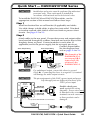
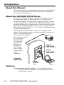
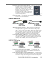
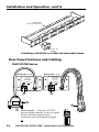
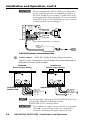
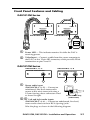
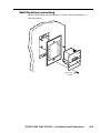
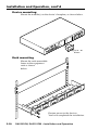
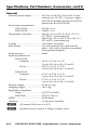
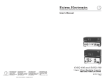
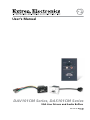
User’s Manual PRELIMINARY DAV101CM Series, DAS101CM Series VGA Line Drivers and Audio Buffers 68-757-01 Rev. D 11 08 Precautions Safety Instructions • English This symbol is intended to alert the user of important operating and maintenance (servicing) instructions in the literature provided with the equipment. This symbol is intended to alert the user of the presence of uninsulated dangerous voltage within the product’s enclosure that may present a risk of electric shock. Caution Read Instructions • Read and understand all safety and operating instructions before using the equipment. Retain Instructions • The safety instructions should be kept for future reference. Follow Warnings • Follow all warnings and instructions marked on the equipment or in the user information. Avoid Attachments • Do not use tools or attachments that are not recommended by the equipment manufacturer because they may be hazardous. Consignes de Sécurité • Français Ce symbole sert à avertir l’utilisateur que la documentation fournie avec le matériel contient des instructions importantes concernant l’exploitation et la maintenance (réparation). Ce symbole sert à avertir l’utilisateur de la présence dans le boîtier de l’appareil de tensions dangereuses non isolées posant des risques d’électrocution. Attention Lire les instructions• Prendre connaissance de toutes les consignes de sécurité et d’exploitation avant d’utiliser le matériel. Conserver les instructions• Ranger les consignes de sécurité afin de pouvoir les consulter à l’avenir. Respecter les avertissements • Observer tous les avertissements et consignes marqués sur le matériel ou présentés dans la documentation utilisateur. Eviter les pièces de fixation • Ne pas utiliser de pièces de fixation ni d’outils non recommandés par le fabricant du matériel car cela risquerait de poser certains dangers. Sicherheitsanleitungen • Deutsch Dieses Symbol soll dem Benutzer in der im Lieferumfang enthaltenen Dokumentation besonders wichtige Hinweise zur Bedienung und Wartung (Instandhaltung) geben. Dieses Symbol soll den Benutzer darauf aufmerksam machen, daß im Inneren des Gehäuses dieses Produktes gefährliche Spannungen, die nicht isoliert sind und die einen elektrischen Schock verursachen können, herrschen. Achtung Lesen der Anleitungen • Bevor Sie das Gerät zum ersten Mal verwenden, sollten Sie alle Sicherheits-und Bedienungsanleitungen genau durchlesen und verstehen. Aufbewahren der Anleitungen • Die Hinweise zur elektrischen Sicherheit des Produktes sollten Sie aufbewahren, damit Sie im Bedarfsfall darauf zurückgreifen können. Befolgen der Warnhinweise • Befolgen Sie alle Warnhinweise und Anleitungen auf dem Gerät oder in der Benutzerdokumentation. Keine Zusatzgeräte • Verwenden Sie keine Werkzeuge oder Zusatzgeräte, die nicht ausdrücklich vom Hersteller empfohlen wurden, da diese eine Gefahrenquelle darstellen können. Instrucciones de seguridad • Español Este símbolo se utiliza para advertir al usuario sobre instrucciones importantes de operación y mantenimiento (o cambio de partes) que se desean destacar en el contenido de la documentación suministrada con los equipos. Este símbolo se utiliza para advertir al usuario sobre la presencia de elementos con voltaje peligroso sin protección aislante, que puedan encontrarse dentro de la caja o alojamiento del producto, y que puedan representar riesgo de electrocución. Precaucion Leer las instrucciones • Leer y analizar todas las instrucciones de operación y seguridad, antes de usar el equipo. Conservar las instrucciones • Conservar las instrucciones de seguridad para futura consulta. Obedecer las advertencias • Todas las advertencias e instrucciones marcadas en el equipo o en la documentación del usuario, deben ser obedecidas. Evitar el uso de accesorios • No usar herramientas o accesorios que no sean especificamente recomendados por el fabricante, ya que podrian implicar riesgos. Warning Power sources • This equipment should be operated only from the power source indicated on the product. This equipment is intended to be used with a main power system with a grounded (neutral) conductor. The third (grounding) pin is a safety feature, do not attempt to bypass or disable it. Power disconnection • To remove power from the equipment safely, remove all power cords from the rear of the equipment, or the desktop power module (if detachable), or from the power source receptacle (wall plug). Power cord protection • Power cords should be routed so that they are not likely to be stepped on or pinched by items placed upon or against them. Servicing • Refer all servicing to qualified service personnel. There are no userserviceable parts inside. To prevent the risk of shock, do not attempt to service this equipment yourself because opening or removing covers may expose you to dangerous voltage or other hazards. Slots and openings • If the equipment has slots or holes in the enclosure, these are provided to prevent overheating of sensitive components inside. These openings must never be blocked by other objects. Lithium battery • There is a danger of explosion if battery is incorrectly replaced. Replace it only with the same or equivalent type recommended by the manufacturer. Dispose of used batteries according to the manufacturer’s instructions. Avertissement Alimentations• Ne faire fonctionner ce matériel qu’avec la source d’alimentation indiquée sur l’appareil. Ce matériel doit être utilisé avec une alimentation principale comportant un fil de terre (neutre). Le troisième contact (de mise à la terre) constitue un dispositif de sécurité : n’essayez pas de la contourner ni de la désactiver. Déconnexion de l’alimentation• Pour mettre le matériel hors tension sans danger, déconnectez tous les cordons d’alimentation de l’arrière de l’appareil ou du module d’alimentation de bureau (s’il est amovible) ou encore de la prise secteur. Protection du cordon d’alimentation • Acheminer les cordons d’alimentation de manière à ce que personne ne risque de marcher dessus et à ce qu’ils ne soient pas écrasés ou pincés par des objets. Réparation-maintenance • Faire exécuter toutes les interventions de réparationmaintenance par un technicien qualifié. Aucun des éléments internes ne peut être réparé par l’utilisateur. Afin d’éviter tout danger d’électrocution, l’utilisateur ne doit pas essayer de procéder lui-même à ces opérations car l’ouverture ou le retrait des couvercles risquent de l’exposer à de hautes tensions et autres dangers. Fentes et orifices • Si le boîtier de l’appareil comporte des fentes ou des orifices, ceux-ci servent à empêcher les composants internes sensibles de surchauffer. Ces ouvertures ne doivent jamais être bloquées par des objets. Lithium Batterie • Il a danger d’explosion s’ll y a remplacment incorrect de la batterie. Remplacer uniquement avec une batterie du meme type ou d’un ype equivalent recommande par le constructeur. Mettre au reut les batteries usagees conformement aux instructions du fabricant. Vorsicht Stromquellen • Dieses Gerät sollte nur über die auf dem Produkt angegebene Stromquelle betrieben werden. Dieses Gerät wurde für eine Verwendung mit einer Hauptstromleitung mit einem geerdeten (neutralen) Leiter konzipiert. Der dritte Kontakt ist für einen Erdanschluß, und stellt eine Sicherheitsfunktion dar. Diese sollte nicht umgangen oder außer Betrieb gesetzt werden. Stromunterbrechung • Um das Gerät auf sichere Weise vom Netz zu trennen, sollten Sie alle Netzkabel aus der Rückseite des Gerätes, aus der externen Stomversorgung (falls dies möglich ist) oder aus der Wandsteckdose ziehen. Schutz des Netzkabels • Netzkabel sollten stets so verlegt werden, daß sie nicht im Weg liegen und niemand darauf treten kann oder Objekte darauf- oder unmittelbar dagegengestellt werden können. Wartung • Alle Wartungsmaßnahmen sollten nur von qualifiziertem Servicepersonal durchgeführt werden. Die internen Komponenten des Gerätes sind wartungsfrei. Zur Vermeidung eines elektrischen Schocks versuchen Sie in keinem Fall, dieses Gerät selbst öffnen, da beim Entfernen der Abdeckungen die Gefahr eines elektrischen Schlags und/oder andere Gefahren bestehen. Schlitze und Öffnungen • Wenn das Gerät Schlitze oder Löcher im Gehäuse aufweist, dienen diese zur Vermeidung einer Überhitzung der empfindlichen Teile im Inneren. Diese Öffnungen dürfen niemals von anderen Objekten blockiert werden. Litium-Batterie • Explosionsgefahr, falls die Batterie nicht richtig ersetzt wird. Ersetzen Sie verbrauchte Batterien nur durch den gleichen oder einen vergleichbaren Batterietyp, der auch vom Hersteller empfohlen wird. Entsorgen Sie verbrauchte Batterien bitte gemäß den Herstelleranweisungen. Advertencia Alimentación eléctrica • Este equipo debe conectarse únicamente a la fuente/tipo de alimentación eléctrica indicada en el mismo. La alimentación eléctrica de este equipo debe provenir de un sistema de distribución general con conductor neutro a tierra. La tercera pata (puesta a tierra) es una medida de seguridad, no puentearia ni eliminaria. Desconexión de alimentación eléctrica • Para desconectar con seguridad la acometida de alimentación eléctrica al equipo, desenchufar todos los cables de alimentación en el panel trasero del equipo, o desenchufar el módulo de alimentación (si fuera independiente), o desenchufar el cable del receptáculo de la pared. Protección del cables de alimentación • Los cables de alimentación eléctrica se deben instalar en lugares donde no sean pisados ni apretados por objetos que se puedan apoyar sobre ellos. Reparaciones/mantenimiento • Solicitar siempre los servicios técnicos de personal calificado. En el interior no hay partes a las que el usuario deba acceder. Para evitar riesgo de electrocución, no intentar personalmente la reparación/mantenimiento de este equipo, ya que al abrir o extraer las tapas puede quedar expuesto a voltajes peligrosos u otros riesgos. Ranuras y aberturas • Si el equipo posee ranuras o orificios en su caja/alojamiento, es para evitar el sobrecalientamiento de componentes internos sensibles. Estas aberturas nunca se deben obstruir con otros objetos. Batería de litio • Existe riesgo de explosión si esta batería se coloca en la posición incorrecta. Cambiar esta batería únicamente con el mismo tipo (o su equivalente) recomendado por el fabricante. Desachar las baterías usadas siguiendo las instrucciones del fabricante. 安全须知 • 中文 警告 这个符号提示用户该设备用户手册中 有重要的操作和维护说明。 电源 • 该 设 备 只 能 使 用 产 品 上 标 明 的 电 源 。 设 备 必须使用有地线的供电系统供电。 第三条线 (地线)是安全设施,不能不用或跳过。 这个符号警告用户该设备机壳内有暴 拔掉电源 • 为安全地从设备拔掉电源,请拔掉所有设备后 或桌面电源的电源线,或任何接到市电系统的电源线。 露的危险电压,有触电危险。 电源线保护 • 妥善布线, 避免被踩踏,或重物挤压。 注意 阅读说明书 • 用 户 使 用 该 设 备 前 必 须 阅 读 并 理 解所有安全和使用说明。 保存说明书 • 用户应保存安全说明书以备将来使 用。 遵守警告 • 用户应遵守产品和用户指南上的所有安 全和操作说明。 维护 • 所有维修必须由认证的维修人员进行。 设备内部没 有用户可以更换的零件。为避免出现触电危险不要自己 试图打开设备盖子维修该设备。 通风孔 • 有些设备机壳上有通风槽或孔,它们是用来防止 机内敏感元件过热。 不要用任何东西挡住通风孔。 锂电池 • 不正确的更换电池会有爆炸的危险。 必须使用与 厂家推荐的相同或相近型号的电池。 按照生产厂的建 议处理废弃电池。 避免追加 • 不要使用该产品厂商没有推荐的工具或 追加设备,以避免危险。 FCC Class A Notice This equipment has been tested and found to comply with the limits for a Class A digital device, pursuant to part 15 of the FCC Rules. Operation is subject to the following two conditions: (1) this device may not cause harmful interference, and (2) this device must accept any interference received, including interference that may cause undesired operation. The Class A limits are designed to provide reasonable protection against harmful interference when the equipment is operated in a commercial environment. This equipment generates, uses, and can radiate radio frequency energy and, if not installed and used in accordance with the instruction manual, may cause harmful interference to radio communications. Operation of this equipment in a residential area is likely to cause harmful interference, in which case the user will be required to correct the interference at his own expense. N This unit was tested with shielded cables on the peripheral devices. Shielded cables must be used with the unit to ensure compliance with FCC emissions limits. DAV101CM, DAS101CM • Safety and Compliances DAV101CM, DAS101CM • Safety and Compliances Quick Start — DAV/DAS101CM Series C Installation and service must be performed by authorized personnel only. These units must be installed in accordance with national and local electrical codes. To install the DAV101CM and DAS101CM modules, see the appropriate section of this manual and follow these steps: Step 1 Install an electrical box or wall bracket (if applicable) and cables. Use cable clamps to hold cables in place for strain relief. Trim back or insulate exposed cable shields with heat shrink to prevent short circuits. See pages 2-2 to 2-3. Step 2 Attach cables to the rear panel. Ensure that power and output cables have been fed through the wallbox/furniture and out the front of the faceplate, frame, or panel. Connect modules to each other (if applicable) and to the power supply, but do not apply power yet. Connect output cables. Unbalanced Balanced Stereo Output Wiring Stereo Output Wiring See the diagrams here and on pages 2-4 to 2-6. N The channels of the 12VDC 0.1 A 12VDC 0.1 A DAS101CM-1/-2/-5 Bottom View DAS101CM-3/-4/-6 Right, ring, – Right, tip, + Ground, sleeve(s), Left, ring, – Left, tip, + See caution. Right, tip, + Gnd, sleeve(s), See caution. Left, tip, + DAS101CM-3/-4 are reversed (R-L instead of L-R) relative to the DAS101CM-1/-2. C For unbalanced output, connect the sleeve to ground (Gnd, _). Connecting the sleeve to a negative (-) terminal will damage the audio output circuits. C The pin assignments of the DAS’s power input and power loop-through ports are different from those of the DAV’s power input. TECHNICAL SUPPORT: 800.633.9876 714.491.1500 www.extron.com MADE IN USA + POWER IN 12V @0.3A DAV101CM (back view) DAS101CM (back view) Power In IN OUT Loop Out to DAV101CM or CIA Interface Double-check your work against the wiring diagrams. Power wires must be attached to the correct terminals on each connector or these products can be damaged. 12 VDC, 1 A DC Power Adapter DAV101CM, DAS101CM • Quick Start Guide iii Quick Start Guide — DAV/DAS101CM, cont’d Step 3 For wall/furniture or rack installations, attach the module(s) to a CPM Series mini architectural adapter plate (MAAP) frame or to a rack-mountable frame. See pages 2-3 and 2-4. Step 4 Attach the front panel input cable(s). Step 5 Verify correct cabling and connector wiring and test the system: power on all the devices and monitor the audio/video output. Each DAV module’s Power LED is lit while the unit receives power. If needed, power off the devices, disconnect the modules’ power supply, correct cabling or wiring errors, then restore power. Step 6 For a DAV101CM, set the sharpness/peaking control using a small screwdriver, as shown at right. See page 2–8. Peaking K IN G Step 7 P E A Disconnect power from the module(s) and other devices. R IVE INE DR AL 01 V1 DA CM Step 8 VG EO R WE PO UT INP VID For wall or furniture mounting, mount the modular connector frame and module(s) to the wall or furniture. For device mounting, mount the module(s) to the device’s faceplate. For rack mounting, mount the rack-mountable frame to the equipment rack. See pages 2-9 and 2-10. For all installations, place the connector plate onto/against the mounting surface and secure it to wall, furniture, device, or rack with the provided screws or bolts. Be careful not to damage the cables. Step 9 Restore power to the devices. You have completed the installation. iv DAV101CM, DAS101CM • Quick Start Guide Table of Contents Chapter One • Introduction..................................................... 1-1 About this Manual..................................................................... 1-2 About the DAV/DAS101CM Series........................................ 1-2 Features......................................................................................... 1-2 DAV101CM Series................................................................... 1-3 DAS101CM Series.................................................................... 1-3 Chapter Two • Installation and Operation. .................. 2-1 Installing a Wall Box or Wall Bracket . ................................ 2-2 Mounting the Module Into a Connector Module Frame or Rack-mountable Frame....................................................... 2-3 Rear Panel Features and Cabling. ......................................... 2-4 DAV101CM Series................................................................... 2-4 DAS101CM Series, and DAV-DAS interconnection............... 2-5 Front Panel Features and Cabling......................................... 2-7 DAV101CM Series................................................................... 2-7 DAS101CM Series.................................................................... 2-7 Adjusting Sharpness (DAV Modules)................................... 2-8 Mounting the Modules. ........................................................... 2-8 Wall/furniture mounting........................................................ 2-9 Device mounting................................................................... 2-10 Rack mounting...................................................................... 2-10 Appendix A • Specifications, Part Numbers, and Accessories .........................................................................................A-1 Specifications...............................................................................A-2 Included Parts..............................................................................A-5 Accessories. ..................................................................................A-5 Cables.............................................................................................A-5 All trademarks mentioned in this manual are the properties of their respective owners. 68-757-01 D 11 08 DAV101CM, DAS101CM • Table of Contents i Table of Contents, cont’d ii DAV101CM, DAS101CM • Table of Contents DAV101CM, DAS101CM 1 Chapter One Introduction About This Manual About the DAV/DAS101CM Series Features Introduction About this Manual This manual contains information about the Extron DAV101CM VGA–QXGA line drivers and DAS101CM Series audio buffers and on how to install them. About the DAV/DAS101CM Series The Extron DAV101CM Series modules are compact, one input, one output, 400 MHz (-3 dB) bandwidth, VGA–QXGA line drivers that amplify the signal from a laptop, desktop, or other computer-video source. Each DAV101CM module buffers and equalizes RGB and sync signals so they can be output on one set of five BNC connectors (DAV101CM-3, -4, or -6) or one 15-pin HD connector (DAV101CM-1, -2, or -5) and sent 150 feet or more on Extron Mini HR cable. The Extron DAS101CM Series modules are compact audio buffers. Each module accepts one unbalanced audio input (on either a 3.5 mm mini tip-ringsleeve jack [DAS101CM-1, -2, or -5] or on a pair of RCA connectors [DAS101CM-3, Projector -4, or -6]) and provides one balanced or Extron unbalanced DAV101CM audio output VGA Line Driver (on a 3.5 mm, Extron 5-pole captive DAS101CM-1 screw Audio Buffer connector). ine AL CM r ve Dri t er Pow VG 01 V1 DA eo Vid DA Inpu S1 01 CM Au dio Bu ffe r A typical application Extron CPM101 Frame Laptop Features Compact design and light weight — These modules can be easily packed into a laptop case, portable projector case, or technician’s tool kit. 1-2 DAV101CM, DAS101CM • Introduction Furniture- and rack-mountable design — The DAV/DAS101CM modules can be mounted in a wall or furniture using a connector module frame and a junction box or a wall bracket. They can also be mounted in products with openings that accommodate this style of connector module or mounted to a CPM Series rack-mountable frame. Choice of colors — The modules are available with black, white, or RAL9010 white faceplates. DAV101CM Series DAV101CM-3 (black) -4 (white) -6 RAL 9010) DAV101CM-1 (black) -2 (white) -5 (RAL9010) Adjustable peaking control — High frequency equalization compensates for signal losses that occur in long cable runs. The DAV101CM can drive signals for up to 150 feet of Extron Mini HR cable or 250 feet of Extron SHR cable. The variable sharpness control lets you select the best peaking setting for the resolution and cable length. Sync signal buffering with AGC — These modules provide sync signal buffering and automatic gain control (AGC) to restore sync signals to proper TTL levels for enhanced stability and reliability over extended cable runs. DAS101CM Series DAS101CM-1 (black) -2 (white) -5 (RAL9010) DAS101CM-3 (black) -4 (white) -6 (RAL9010) Balanced or unbalanced audio output — Unbalanced, line level stereo audio inputs can be output as balanced or unbalanced stereo audio. Power loop-through for a paired DAV101CM — A DAS101CM can be mounted in a faceplate together with a DAV101CM and share a single power supply so audio and computer DAV101CM, DAS101CM • Introduction 1-3 Introduction, cont’d video can be input, buffered, and driven from the same location. 1-4 DAV101CM, DAS101CM • Introduction DAV101CM, DAS101CM 2 Chapter Two Installation and Operation Installing a Wall Box or Wall Bracket Mounting the Module Into a Connector Module Frame or Rack-mountable Frame Rear Panel Features and Cabling Front Panel Features and Cabling Adjusting Sharpness (DAV Modules) Mounting the Modules Installation and Operation The DAV/DAS101CM modules can be attached to a CPM mini architectural adapter plate (MAAP) mounting frame and mounted in a wall or furniture using either a one-gang wall box or a wall bracket. Alternatively they can be mounted in the chassis of a device (such as a CIA Series interface) that accommodates connector modules, or attached to a CPM Series rack-mountable frame for mounting in a standard equipment rack. Installing a Wall Box or Wall Bracket For wall and furniture mounting installations, the installation site must be deep enough for both the wall box (or the DAV/ DAS, if using a wall bracket) and the cables. The box should be at least 2.5" (6.4 cm) deep. Install cables into the wall, furniture, or conduits before installing a wall box or bracket. 1. Place the wall box or mounting bracket against the installation surface; mark the guidelines for the opening on the wall or furniture. 2. Cut out the material from the marked area. 3. Insert the wall box/bracket to check the opening’s size and fit. Enlarge or smooth the edges of the opening if needed. 4. Feed cables through the wall box’s punch-out holes, ground shields, and Screw secure cables with cable clamps to Braided provide strain relief. Shield } Grounding shields W To prevent Cable Clamp Install Cable Metal Wall Box Foil Shield short circuits, the outer foil shield can be cut back to the point where the cable exits the cable clamp. Connect both braided and foil shields to an equipment ground at the other end of the cable. Insulate any exposed shields with heat shrink 2-2 5. Insert the wall box or wall bracket into the opening, and attach it to the wall, stud, or furniture, leaving the front edge flush with the outer wall or furniture surface. To attach a wall box to wood, use four #8 or #10 screws or 10-penny nails. A minimum of 1/2 inch (1.3 cm) of screw threads must penetrate the wood. To attach a wall box to metal, use four #8 or #10 self-tapping sheet metal screws or machine bolts with matching nuts. DAV101CM, DAS101CM • Installation and Operation 1-gang wall box.eps Wall Stud Installation Cable Cable Clamp Screws or Nails Wall opening is flush with edge of box. Attaching a wall box to a wall stud 7. Mount the module(s) onto a mounting frame, then cable and test the DAV/DAS before fastening it into the wall box or bracket. The cables are inaccessible after installation. Mounting the Module Into a Connector Module Frame or Rack-mountable Frame For wall, furniture, or rack mounting installations. DAV and DAS modules must be attached to a faceplate, frame, or CPM Series rack-mountable frame and cabled before being installed. 1. Insert the module into the faceplate's or frame’s opening. 2. Secure the module to the faceplate or frame with the provided machine screws and nuts. OR NIT N MO TIO ULA EM L TA ON N RIZ IO HOOSIT P UT R WE PO T PU IN ECT L SE TP OU 1 R UT ITO INP MON L CA UT UT EO C IA MP UT ER G IN INP INP IN TE INE IV DR AL M 1C VG 0 V1 DA WE R PO T EO U INP VID A CO ER UT DIO AU UT 2 11 A K UT INP VID PU IO UD INP VID P E CO EO R TE ER UT MP LO M CO TP OU 2 R UT NITO INP MO L CA LO RF AC E (4) #4 - 40 Screws Attaching a DAS/DAV101CM to a device’s faceplate DAV101CM, DAS101CM • Installation and Operation 2-3 DAV101CM w CPM112R-1_10-16-03.eps P E A K IN G Installation and Operation, cont’d IVER NE DR A LI M VG 1C WER PO V10 DA T IN G O K A P E CPM112R-1 A/V Connector Panel INPU VIDE IVER NE DR A LI M VG WER PO 1C V10 DA T O INPU P E A K IN G VIDE NE IVER DR A LI 1C DA M VG WER PO V10 T G O INPU P E A K IN VIDE IVER NE DR A LI M VG WER PO 1C DA V10 T O INPU P E A K IN G VIDE IVER NE DR A LI 1C DA M WER VG PO V10 T INPU O P E A K IN G VIDE IVER NE DR A LI M VG PO 1C V10 DA VIDE O IN PU WER T (4) #4 - 40 Screws Attaching a DAS/DAV to a CPM rack-mountable frame Rear Panel Features and Cabling DAV101CM Series DAV101CM-1, -2, -5 TECHNICAL SUPPORT: 800.633.9876 714.491.1500 www.extron.com MADE IN USA + POWER IN 12V @0.3A 1 DAV101CM-3, -4, -6 TECHNICAL SUPPORT: 800.633.9876 714.491.1500 www.extron.com MADE IN USA + POWER IN 12V @0.3A 1 2 3 a 2-4 Power input — Connect a 12 VDC power supply directly to this two-pole direct insertion captive screw connector (see the diagram at right), or + DAV101CM, DAS101CM • Installation and Operation connect the power supply to a DAS101CM module’s 12 VDC In port and loop the power through to the DAV101CM via the DAS101CM’s 12 VDC Out port (see page 2-6). N Do not tin the stripped power supply leads before installing the captive screw connector. C Correct polarity is important! The power wires must be attached to the correct terminals or the module can be damaged. b c 15-pin HD computer-video output (DAV101CM-1, -2, -5) — Attach this connector to the display’s 15-pin HD input connector. BNC computer-video output (DAV101CM-3, -4, -6) — Attach these five male BNC connectors to the display’s BNC input connectors. DAS101CM Series, and DAV-DAS interconnection DAS101CM-1, -2, -5 Top View 12VDC 0.1 A 12VDC 0.1 A 1 2 3 DAS101CM-1, -2, -5 Rear View a DAS101CM-3, -4, -6 Top View 1 2 3 DAS101CM-3, -4, -6 Rear View 12 VDC, 0.1 A In (power input) — Connect a 12VDC, 1 A power supply to these two poles of the DAS’s 4-pole direct insertion captive screw connector for power input. C Correct polarity is important! The power wires must be attached to the correct terminals or the module can be damaged. b 12 VDC, 0.1 A Out (power loop-through for DAV101CM modules) — This port allows power to be looped through to a DAV101CM. See the wiring diagram on the next page. DAV101CM, DAS101CM • Installation and Operation 2-5 Installation and Operation, cont’d C The pin assignments of the DAS’s power input and power loop-through ports are different from those of the DAV modules’ power input. Double-check your work against the wiring diagram. Power wires must be attached to the correct terminals on each connector or these products can be damaged. TECHNICAL SUPPORT: 800.633.9876 714.491.1500 www.extron.com MADE IN USA + POWER IN 12V @0.3A DAV101CM (back view) DAS101CM (back view) Power In IN OUT Loop Out to DAV101CM or CIA Interface 12 VDC, 1 A DC Power Adapter DAV-DAS power interconnection c Audio output — Wire this 5-pole, 3.5 mm, direct insertion captive screw connector as shown below for either balanced or unbalanced stereo audio output. Unbalanced Stereo Output Wiring Balanced Stereo Output Wiring 12VDC 0.1 A 12VDC 0.1 A DAS101CM-1/-2/-5 Bottom View DAS101CM-3/-4/-6 Right, ring, – Right, tip, + Ground, sleeve(s), Left, ring, – Left, tip, + See caution. Right, tip, + Gnd, sleeve(s), See caution. Left, tip, + N The left and right channels of the DAS101CM-3/-4/-6 are reversed (R-L instead of L-R) relative to the DAS101CM-1/-2/-5, as shown above. C For unbalanced output, connect the sleeve to ground (Gnd, _). Connecting the sleeve to a negative (-) terminal will damage the audio output circuits. 2-6 DAV101CM, DAS101CM • Installation and Operation Front Panel Features and Cabling DAV101CM Series 1 DAV101CM VGA LINE DRIVER 1 DAV101CM VGA LINE DRIVER POWER POWER VIDEO INPUT VIDEO INPUT DAV101CM-3/-4/-6 DAV101CM-1/-2/-5 2 a b 2 Power LED — This indicator remains lit while the DAV is receiving power. Video Input — Connect a cable from the source computer to the DAV via this 15-pin HD connector, which provides ID bit termination on pins 4 and 11. DAS101CM Series DAS101CM-1, -2, -5 DAS101CM-3, -4, -6 DAS101CM AUDIO BUFFER DAS101CM AUDIO BUFFER 1 a Stereo audio input (DAS101CM-1, -2, -5) — Connect an unbalanced, line level stereo audio source to this mini stereo jack using a 3.5 mm tip-ring-sleeve connector wired as shown at right. 2 3 Tip (L) Ring (R) Sleeve ( ) 3.5 mm Stereo Plug (unbalanced) Left and right audio inputs b,c (DAS101CM-3, -4, -6) — Connect an unbalanced, line level, stereo audio source to these RCA (tip-ring) jacks. Wire the plugs as shown in the following diagram. DAV101CM, DAS101CM • Installation and Operation 2-7 Audio RCA connector color.eps Installation and Operation, cont’d Tip (Signal) Right Channel (Red Jacket) Sleeve (Gnd ) Left Channel (White Jacket) Tip (+) Sleeve ( ) RCA connector wiring for DAS101CM-3,-04 audio input Adjusting Sharpness (DAV Modules) The longer the cable being used, the greater the signal loss. The DAV101CMs have an adjustable sharpness/peaking control that equalizes the video signal to compensate for signal losses. The DAV101CM can drive signals for up to 150 feet of Extron mini HR cable or 250 feet of Extron SHR cable. G IN K E A P While viewing the output image, use a small screwdriver to rotate this potentiometer to select the setting that gives the clearest pictures. Peaking R IVE INE DR AL 01 V1 DA CM VG EO C Using a larger screwdriver can break the potentiometer. R WE PO UT INP VID Mounting the Modules Test the system. Adjust the sharpness (see "Adjusting Sharpness") or disconnect the power and correct any cabling or wiring errors before mounting the modules. C To avoid the risk of electrical shock, disconnect power from the DAV or DAS module before mounting it. For all installations, place the DAV’s or DAS’s faceplate (or the mounting frame it is attached to) onto/against the mounting surface and secure it with the provided screws or bolts. Be careful not to damage the cables. 2-8 DAV101CM, DAS101CM • Installation and Operation DAV-DAS101CM-1 w CPM101_10-16-03.eps Wall/furniture mounting P E A K IN G Mount the frame and module(s) to the wall or furniture, as shown below. R IVE INE DR AL DA M 1C 10 VG r we Po V t pu o In ide V DA S1 01 CM Au dio Bu ffe r (8) #4 - 40 Screws DAV101CM, DAS101CM • Installation and Operation 2-9 Installation and Operation, cont’d Device mounting P E A K IN G Mount the module(s) to the device’s faceplate, as shown below. NE DR IVER A LI VG WER PO DAV101CM Rack mount_10-16-03.eps M 1C DAV 10 O VIDE T INPU (4) #4 - 40 Screws Rack mounting P E A K IN G Mount the rack-mountable frame to the equipment rack as shown below. IVER NE DR A LI M VG WER PO 1C V10 DA T O INPU P E A K IN G VIDE IVER NE DR A LI M VG WER PO 1C V10 DA T O INPU P E A K IN G VIDE NE IVER DR A LI 1C DA M VG WER PO V10 T O INPU P E A K IN G VIDE IVER NE DR A LI 1C DA M VG WER PO V10 T O INPU P E A K IN G VIDE IVER NE DR A LI M VG WER PO 1C DA V10 T O INPU P E A K IN G VIDE IVER NE DR A LI 1C DA M VG WER PO V10 T O INPU VIDE Restore power to the devices. You have completed the installation. 2-10 DAV101CM, DAS101CM • Installation and Operation DAV101CM, DAS101CM A Appendix A Specifications, Part Numbers, and Accessories Specifications Included Parts Accessories Cables Specifications, Part Numbers, and Accessories Specifications Video— DAV101CM Gain������������������������������������������������� Unity Bandwidth�������������������������������������� 400 MHz (-3 dB) Video input— DAV101CM Number/signal type��������������������� 1 VGA–QXGA RGBHV, RGBS, RGsB, RsGsBs, or HDTV component video Connectors������������������������������������� (1) 15-pin HD female Nominal level�������������������������������� 1 Vp-p for Y of component video 0.7 Vp-p for RGB and for R-Y and B-Y of component video Minimum/maximum levels�������� Analog: 0.3 V to 1.5 Vp-p with no offset Impedance�������������������������������������� 75 ohms Horizontal frequency�������������������� 15 kHz to 175 kHz Vertical frequency�������������������������� 30 Hz to 150 Hz Return loss�������������������������������������� <-40 dB @ 5 MHz Video output— DAV101CM Number/signal type��������������������� 1 VGA–QXGA RGBHV, RGBS, RGsB, RsGsBs, or HDTV component video Connectors DAV101CM-1, -2, -5���������� (1) 15-pin HD female on a 6" (15 cm) pigtail DAV101CM-3, -4, -6���������� (1) set of 5 BNC female on 6.25" to 7" (15.9 to 17.8 cm) pigtails Nominal level�������������������������������� 1 Vp-p for Y of component video 0.7 Vp-p for RGB and for R-Y and B-Y of component video Minimum/maximum levels�������� Analog: 0.3 V to 1.5 Vp-p (follows input) Impedance�������������������������������������� 75 ohms Return loss�������������������������������������� <-40 dB @ 5 MHz DC offset����������������������������������������� ±50 mV with input at 0 offset Sync— DAV101CM Input type��������������������������������������� RGBHV, RGBS, RGsB, RsGsBs, bi-level and tri-level sync Output type������������������������������������ RGBHV, RGBS, RGsB, RsGsBs, bi-level and tri-level sync (follows input) Input level�������������������������������������� 1.7 V to 5.0 Vp-p Output level����������������������������������� TTL: 5.0 Vp-p, unterminated A-2 DAV101CM, DAS101CM • Specifications, Part #s, Accessories Input impedance��������������������������� 510 ohms Output impedance������������������������ <50 ohms Max. propagation delay��������������� <25 ns Max. rise/fall time������������������������ <5 ns Polarity������������������������������������������� Positive or negative (follows input) Audio— DAS101CM Gain������������������������������������������������� Unbalanced output: 0 dB; Balanced output: +6 dB Frequency response���������������������� 20 Hz to 20 kHz, ±0.5 dB THD + Noise���������������������������������� <0.025% @ 1 kHz, <0.020% @ 20 kHz at nominal level S/N�������������������������������������������������� >100 dB at maximum output (unweighted) Stereo channel separation DAS101CM-1, -2, -5����������� >56 dB @ 20 Hz to 10 kHz DAS101CM-3, -4, -6����������� >75 dB @ 20 Hz to 10 kHz Audio input— DAS101CM Number/signal type��������������������� 1 stereo, unbalanced, line level Connectors DAS101CM-1, -2, -5����������� (1) 3.5 mm mini audio jack (tip-ringsleeve), female DAS101CM-3, -4, -6����������� 1 pair of RCA (tip-ring) jacks, female Impedance�������������������������������������� >10 kohms unbalanced, DC coupled Nominal level�������������������������������� -10 dBV (316 mVrms) Maximum level������������������������������ +6 dBu, (balanced or unbalanced) at 1% THD+N N 0 dBu = 0.775 Vrms, 0 dBV = 1 Vrms, 0 dBV ≈ 2 dBu Audio output— DAS101CM Number/signal type��������������������� 1 stereo, balanced/unbalanced Connectors������������������������������������� (1) 3.5 mm direct insertion captive screw connector, 5 pole Impedance�������������������������������������� 50 ohms unbalanced, 100 ohms balanced Nominal level�������������������������������� -2 dBu (0.632 Vrms) for balanced output Maximum level (Hi-Z)����������������� >+15 dBu, balanced or unbalanced at 1% THD+N Maximum level (600 ohm)����������� >+13 dBm, balanced or unbalanced at 1% THD+N DAV101CM, DAS101CM • Specifications, Part #s, Accessories A-3 Specifications, Part Numbers, Accessories, cont’d General External power supply����������������� 100 VAC to 240 VAC, 50/60 Hz, 3 watts, external, to a 12 VDC, 1 A power supply (#70-055-01 included for the DAV101CM, optional for the DAS101CM). Power input requirements DAV101CM������������������������ 12 VDC, 0.3 A DAS101CM������������������������� 12VDC, 0.1 A Temperature/humidity���������������� Storage: -40 to +158 °F (-40 to +70 °C) / 10% to 90%, noncondensing Operating: +32 to +113 °F (0 to +45 °C) / 10% to 90%, noncondensing Cooling������������������������������������������� Convection, unvented Rack mount������������������������������������ Yes, with optional rack shelf and face plates. Also wall or furniture mountable with optional faceplates Enclosure type������������������������������� Metal Enclosure dimensions DAV101CM Faceplate��������������������� 1.4" H x 2.2" W x 0.1" D (3.6 cm H x 5.6 cm W x 0.2 cm D) Device������������������������� 1.4" H x 1.4" W x 1.2" D (3.6 cm H x 3.6 cm W x 3.0 cm D) DAS101CM Faceplate��������������������� 0.7" H x 2.2" W x 0.1" D (1.8 cm H x 5.6 cm W x 0.2 cm D) Device������������������������� 0.7" H x 1.4" W x 1.3" D (1.8 cm H x 3.6 cm W x 3.3 cm D) Product weight������������������������������ 0.2 lbs (0.1 kg) Shipping weight���������������������������� 1 lb (1 kg) Regulatory compliance Safety����������������������������������� CE, ETL (UL1950) EMI/EMC�������������������������� CE, FCC Class A MTBF����������������������������������������������� 30,000 hours Warranty����������������������������������������� 3 years parts and labor N All nominal levels are at ±10%. N Specifications are subject to change without notice. A-4 DAV101CM, DAS101CM • Specifications, Part #s, Accessories Included Parts These items are included in each order for a DAS/DAV101CM: Included parts Replacement part number DAV101CM-1, -2, -5 (15-pin HD output [black, white, RAL9010 white]) 60-612-11, -21, -51 DAV101CM-3, -4, -6 (BNC output [black, white, RAL9010 white]) 60-613-11, -21, -51 DAS101CM-1, -2, -5 (mini jack input [black, white, RAL9010 white]) 60-610-11, -21, -51 DAS101CM-3, -4, -6 (RCA input [black, white, RAL9010 white]) 60-611-11, -21, -51 12VDC, 1 A external power supply (DAV only) 70-055-01 3/32" hex wrench 4-40 hex socket cap screws (4 per DAV, 2 per DAS) User’s manual Accessories Accessories Part number 12 VDC, 1 A external power supply 70-055-01 CPM112R 1U high, full rack width frame 60-584-12 CPM 133 1U high, one-third rack width frame 60-584-15 CPM120 connector frame 60-588-11 (optional for DAS models) CIA111, CIA112, CIA116 interfaces same as model name Male-to-female VGA cables w/audio Part number Cables VGA 3' HRA, VGA 6' HRA 26-491-01, -02 VGA 12' HRA, VGA 25' HRA 26-491-03, -04 VGA 35' HRA, VGA 50' HRA 26-491-07, -08 DAV101CM, DAS101CM • Specifications, Part #s, Accessories A-5 Specifications, Part Numbers, and Accessories A-6 DAV101CM, DAS101CM • Specifications, Part #s, Accessories Extron’s Warranty Extron Electronics warrants this product against defects in materials and workmanship for a period of three years from the date of purchase. In the event of malfunction during the warranty period attributable directly to faulty workmanship and/or materials, Extron Electronics will, at its option, repair or replace said products or components, to whatever extent it shall deem necessary to restore said product to proper operating condition, provided that it is returned within the warranty period, with proof of purchase and description of malfunction to: USA, Canada, South America, and Central America: Extron USA 1001 East Ball Road Anaheim, CA 92805 U.S.A. Europe, Africa, and the Middle East: Extron Europe Hanzeboulevard 10 3825 PH Amersfoort The Netherlands Asia: Extron Asia 135 Joo Seng Road #04-01 PM Industrial Bldg. Singapore 368363 Singapore Japan: Extron Japan Kyodo Building, 16 Ichibancho Chiyoda-ku, Tokyo 102-0082 Japan China: Extron China 686 Ronghua Road Songjiang District Shanghai 201611 China Middle East: Extron Middle East Dubai Airport Free Zone F12, PO Box 293666 United Arab Emirates, Dubai This Limited Warranty does not apply if the fault has been caused by misuse, improper handling care, electrical or mechanical abuse, abnormal operating conditions or nonExtron authorized modification to the product. If it has been determined that the product is defective, please call Extron and ask for an Applications Engineer at (714) 491-1500 (USA), 31.33.453.4040 (Europe), 65.6383.4400 (Asia), or 81.3.3511.7655 (Japan) to receive an RA# (Return Authorization number). This will begin the repair process as quickly as possible. Units must be returned insured, with shipping charges prepaid. If not insured, you assume the risk of loss or damage during shipment. Returned units must include the serial number and a description of the problem, as well as the name of the person to contact in case there are any questions. Extron Electronics makes no further warranties either expressed or implied with respect to the product and its quality, performance, merchantability, or fitness for any particular use. In no event will Extron Electronics be liable for direct, indirect, or consequential damages resulting from any defect in this product even if Extron Electronics has been advised of such damage. Please note that laws vary from state to state and country to country, and that some provisions of this warranty may not apply to you. Extron USA - West Headquarters +800.633.9876 Inside USA / Canada Only +1.714.491.1500 +1.714.491.1517 FAX Extron USA - East Extron Europe Extron Asia Extron Japan Extron China Extron Middle East +800.633.9876 +800.3987.6673 +800.7339.8766 +81.3.3511.7655 +81.3.3511.7656 FAX +400.883.1568 +971.4.2991800 +971.4.2991880 FAX +1.919.863.1794 +1.919.863.1797 FAX +31.33.453.4040 +31.33.453.4050 FAX +65.6383.4400 +65.6383.4664 FAX Inside USA / Canada Only Inside Europe Only Inside Asia Only © 2008 Extron Electronics. All rights reserved. Inside China Only +86.21.3760.1568 +86.21.3760.1566 FAX