1
DVD RECEIVER AMP
BASIC MODEL : HT-Q9
SERVICE
DVD RECEIVER AMP SYSTEM
Manual
Features
* Multi-Disc Playback & FM Tuner
* Dolby Pro Logic II
* DTS (Digital Theater Systems)
* TV Screen Saver Function
* Power Saving Function
* Customized TV Screen Display
MODEL : HT-Q9
- Confidential -
ELECTRONICS
© Samsung Electronics Co.,Ltd. AUG. 2006
Printed in Korea
Code no. AH68-01893Q
INDEX
Ch1
Ch8
Precautions
1-1. Safety Precautions
1-2. Servicing Precautions
1-3. Precautions for Electrostatically
Sensitive Device (ESDs)
1-4. Special Precations and Waring
Lables for Laser Products
1-5. Special Precautions for HDD
1-1
1-2
1-3
1-4
1-5
Electrical Parts List
Electrical Parts List
Ch9
Block Diagram
1. MAIN BLOCK DIAGRAM
Ch10
Ch2
Product Descriptions
1. Product Feature
2. Specifications
3. Accessories
2-1
2-2
2-3
Product Functions
1. Connecting the Speakers
2. Basic Functions
3. New Functions
Ch4
3-1
3-3
3-10
Adjustments
No Reference
Ch5
How to disassemble
How to disassemble
Ch6
No Reference
Ch11
PCB Diagram
Ch12
11-1
Schematic Diagram
1. MAIN-1
12-1
2. MAIN-2
12-2
3. AMP
12-3
4. FUNCTION
12-4
5. RF
12-5
6. SMSP
12-6
Ch13
Circuit Description
1. Description
13-1
2. Function Description
13-3
Troubleshooting
1. Main (Power)
2. Output Failure (for 2Ch Analog Input)
Ch7
5-1
9-1
Wiring Diagram
1. PCB Layout
Ch3
8-1
6-1
6-2
Exploded View & Parts List
1. Total Exploded View
2. Parts List
7-1
7-2
Ch14
HTS Reference
1. HTS (Home Thater Sytsem)
14-1
2. About “Sound”
14-2
3. 5.1 Channel Sound
14-3
4. HTS Sonud Format
14-4
5. HTS Devices
14-5
1. Precautions
Follow these safety, servicing and ESD precautions to prevent damage and protect against potential hazards
such as electrical shock and X-rays.
1-1 Safety Precautions
1. Be sure that all of the built-in protective
devices are replaced.
2. When reinstalling the chassis and its
assemblies, be sure to restore all protective
devices, including control knobs and
compartment covers.
3. Make sure that there are no cabinet
openings through which people-particularly children--might insert fingers
and contact dangerous voltages. Such
openings include the spacing between the
picture tube and the cabinet mask,
excessively wide cabinet ventilation slots,
and improperly fitted back covers.
4. Design Alteration Warning:
Never alter or add to the mechanical or
electrical design of the unit. Example: Do
not add auxiliary audio or video connectors. Such alterations might create a safety
hazard. Also, any design changes or additions will void the manufacturer's warranty.
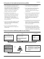
5. Leakage Current Hot Check (Figure 1-1):
Warning: Do not use an isolation
transformer during this test. Use a leakagecurrent tester or a metering system that
complies with American National Standards
Institute (ANSI C101.1, Leakage Current for
Appliances), and Underwriters Laboratories
(UL Publication UL1410, 59.7).
Fig. 1-1 AC Leakage Test
6. Insulation Resistance Cold Check:
(1) With the unit's AC plug disconnected
from the AC source, connect an electrical
jumper across the two AC prongs. (2) Set
the power switch to ON. (3) Measure the
resistance between the shorted AC plug and
any exposed metallic parts. Example:
Screwheads, antenna, control shafts or
handle brackets.
If any of the exposed metallic parts has a
return path to the chassis, the measured
resistance should be between 1 and 5.2
megohms. If there is no return path, the
measured resistance should be "infinite." If
the resistance is outside these limits, a shock
hazard might exist. See Figure 1-2
With the unit completely reassembled, plug
the AC line cord directly into a 120V AC
outlet. With the unit's AC switch first in
the ON position and then OFF, measure the
current between a known earth ground
(metal water pipe, etc.) and all exposed
metal parts. Examples: Handle brackets,
metal cabinets, screwheads and control
shafts. The current measured should not
exceed 0.5 milliamp. Reverse the powerplug prongs in the AC outlet and repeat.
Fig. 1-2 Insulation Resistance Test
Samsung Electronics
1-1
Precautions
1-1 Safety Precautions (Continued)
7. Components, parts and wiring that appear
to have overheated or that are otherwise
damaged should be replaced with parts
that meet the original specifications.
Always determine the cause of damage or
overheating, and correct any potential
hazards
8. Observe the original lead dress, especially
near the following areas: Antenna
wiring, sharp edges, and especially the
AC and high voltage power supplies.
Always inspect for pinched, out-of-place,
or frayed wiring. Do not change the
spacing between components and the
printed circuit board. Check the AC
power cord for damage. Make sure that
no wires or components touch thermally
hot parts.
9. Product Safety Notice:
Some electrical and mechanical parts
have special safety-related characteristics
which might not be obvious from visual
inspection. These safety features and the
protection they give might be lost if the
replacement component differs from the
original--even if the replacement is rated
for higher voltage, wattage, etc.
10 Components that are critical for safety are
indicated in the circuit diagram by
shading,
or
. Use replacement
components that have the same ratings,
especially for flame resistance and
dielectric strength specifications. A
replacement part that does not have the
same safety characteristics as the original
might create shock, fire or other hazards.
1-2 Servicing Precautions
Warning1:
First read the "Safety Precautions" section of this manual. If some unforeseen circumstance creates a conflict
between the servicing and safety precautions, always follow the safety precautions.
1. Servicing precautions are printed on the
cabinet. Follow them.
2. Always unplug the unit's AC power cord
from the AC power source before
attempting to: (a) Remove or reinstall any
component or assembly, (b) Disconnect an
electrical plug or connector, (c) Connect a
test component in parallel with an
electrolytic capacitor.
3. Some components are raised above the
printed circuit board for safety. An
insulation tube or tape is sometimes used.
The internal wiring may be clamped to
prevent contact with thermally hot
components. Reinstall all such elements to
their original position.
4. After servicing, always check that the
screws, components and wiring have been
correctly reinstalled. Make sure that the
portion around the serviced part has not
been damaged.
1-2
5. Check the insulation between the blades of
the AC plug and accessible conductive parts
(examples: metal panels, input terminals
and earphone jacks).
6. Insulation Checking Procedure: Disconnect
the power cord from the AC source and
turn the power switch ON. Connect an
insulation resistance meter (500V) to the
blades of the AC plug.
The insulation resistance between each
blade of the AC plug and accessible
conductive parts (see above) should be
greater than 1 megohm.
7. Never defeat any of the B+ voltage
interlocks. Do not apply AC power to the
unit (or any of its assemblies) unless all
solid-state heat sinks are correctly installed.
8. Always connect a test instrument's ground
lead to the instrument chassis ground
before connecting the positive lead; always
remove the instrument's ground lead last.
Samsung Electronics
Precautions
1-3 Precautions for Electrostatically Sensitive Devices (ESDs)
1. Some semiconductor ("solid state") devices
are easily damaged by static electricity.
Such components are called Electrostatically
Sensitive Devices (ESDs). Examples include
integrated circuits and some field-effect
transistors. The following techniques will
reduce the occurrence of component
damage caused by static electricity.
5. Use only a grounded-tip soldering iron
when soldering or unsoldering ESDs.
2. Immediately before handling any
semiconductor components or assemblies,
drain the electrostatic charge from your
body by touching a known earth ground.
Alternatively, wear a discharging
wrist-strap device. (Be sure to remove it
prior to applying power--this is an electric
shock precaution.)
7. Do not remove a replacement ESD from its
protective package until you are ready to
install it. Most replacement ESDs are
packaged with leads that are electrically
shorted together by conductive foam,
aluminum foil or other conductive
materials.
6. Use only an anti-static solder removal
device. Many solder removal devices are
not rated as "anti-static" (these can
accumulate sufficient electrical charge to
damage ESDs).
8. Immediately before removing the protective
material from the leads of a replacement
ESD, touch the protective material to the
chassis or circuit assembly into which the
device will be installed.
3. After removing an ESD-equipped assembly,
place it on a conductive surface such as
aluminum foil to prevent accumulation of
electrostatic charge.
4. Do not use freon-propelled chemicals.
These can generate electrical charges that
damage ESDs.
9. Minimize body motions when handing
unpackaged replacement ESDs. Motions
such as brushing clothes together, or lifting
a foot from a carpeted floor can generate
enough static electricity to damage an ESD.
1-4 Special Precautions and Warning Labels for Laser Products
(UL)
(CSA)
This Product Complies with
DHHS Rules 21CFR, Sub
chapter J.At date of Manufacture
(UL,CSA,EU)
CERTIFIED ONLY TO CANADIAN
ELECTRICAL CODE.
CLASS 1
LASER PRODUCT
CERTIFIE EN VERTU DU CODE
CANADIAN DE LELETRICITE
SEULEMENT
Fig. 1-3 Warning Labels (Location: Enclosure Block)
(UL,CSA,SCAN)
CAUTION : INVISIBLE LASER RADIATION WHEN OPEN
AND INTERLOCKS DEFEATEO AVOIDEXPOSURE TO BEAM
ADVARSEL: USYNLIG LASERSTRÅLING VED ABNING
NÅR SIKKERHEDSAFBRYDERE ER UDE AF FUNKTION
UNDGA UDSAETTELSE FOR STRALING
VARO:AVATTAESSA JA SUOJALUKITUS OHITETTAESSA
OLET ALTTINA NAKYMATTÖMALLE LASERSATEILYLLE ALA
KATSO SATEESEEN!
VARNING:OSYNLIG LASERSTRÅLNING NAR DENNA DEL
(EU)
UL
CSA
EU
SCAN
: Manufactured for U.S.A. Market.
: Manufactured for Canadian Market.
: Manufactured for European Market.
: Manufactured for Scandinavian
Market.
AR OPPNAD OCH SPARREN AR URKOPPLAD BETRAKTA
EJSTRÅLEN!
Fig. 1-4 Warning Labels (Location: Disc Clamper, Inner Side of Unit Door or Nearby Unit Chassis )
Samsung Electronics
1-3
Precautions
1-4 Special Precautions and Warning Labels for Laser Products (Continued)
1-4-1 Warnings
1. When servicing, do not approach the LASER
exit with the eye too closely. In case it is
necessary to confirm LASER beam emission,
be sure to observe from a distance of more
than 30 cm from the surface of the objective
lens on the optical pick-up block.
2. Do not attempt to handle the objective lens
when the DISC is not on the tray.
1-4-2 Laser Diode Specifications
Material: GaAs+ GaAlAs
Wavelength: 760-800 nm
Emission Duration: Continuous
Laser Output: 0.2 mw (measured at a
1.6 mm distance from the objective lens
surface on the optical pick-up block.)
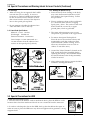
1-4-3 Handling the Optical Pick-up
1. Static electricity from clothing or the body
may cause electrostatic breakdown of the
laser diode in the Optical Pickup. Follow
this procedure:
2. Place a conductive sheet on the work bench
(i.e., the black sheet used for wrapping
repair parts.) Note: The surface of the work
bench should be covered by a copper
ground plane, which is grounded.
3. The repair technician must wear a wrist
strap which is grounded to the copper sheet.
4. To remove the Optical Pickup block:
Place the set on the conductive sheet, and
momentarily touch the conductive sheet
with both hands. (While working, do not
allow any electrostatic sources--such as
clothes--to touch the unit.)
5. Ground the "Short Terminal" (located on the
PCB, inside the Pickup Assembly) before
replacing the Pickup. This terminal should
be shorted whenever the Pickup Assembly
is lifted or moved.
6. After replacing the Pickup, reopen the Short
Terminal. See diagrams below:
1-5 Special Precautions for HDD
* HDD Data Maintenance Step
1. Since the data on the HDD is weak to mechanical shock, place the HDD in a safe
location that is free from mechanical shock once it is removed from the main unit.
2. In order to safe keep the data on the HDD, back up the data before the repair or
make sure not to place the HDD near any electrical appliance that generates a strong
magnetic field.
1-4
Samsung Electronics
2. Product Descriptions
1. Product Feature
Product Feature
Multi-Disc Playback &
■
The HT-Q9 combines the convenience of multi-disc playback capability,
including DVD-VIDEO, VCD, CD, MP3-CD, WMA-CD, DivX, CD-R/RW,
FM Tuner
and DVD-R/RW, with a sophisticated FM tuner, all in a single player.
■
Dolby Pro Logic II
DTS
Dolby Pro Logic II is a new form of multi-channel audio signal
decoding technology that improves upon existing Dolby Pro Logic.
■
(Digital Theater Systems)
DTS is an audio compression format developed by Digital Theater
Systems Inc. It delivers full-frequency 5.1 channel sound.
■
TV Screen Saver
Function
The HT-Q9 automatically brightens and darkens your TV screen after 3
minutes in the stop mode. The HT-Q9 automatically switches itself into
the power saving mode after 20 minutes in the screen saver mode.
Power Saving Function
Customized TV Screen
Display
2-1
■
The HT-Q9 automatically shuts itself off after 20 minutes in stop mode.
■
The HT-Q9 allows you to select your favorite image during JPEG,
DVD or VCD playback and set it as your background wallpaper.
Samsung Electronics
2. Specifications
G
E
N
E
R
A
L
T
F U
N
M E
R
V
I
D
E
O
O
U
T
P
U
T
A
M
P
L
I
F
I
E
R
Power Consumption
Weight
Dimensions (W x H x D)
Operating Temperature Range
Operating Humidity Range
Usable Sensitivity
S/N Ratio
Distortion
Composite Video
Component Video
Front speaker output
Center speaker output
Rear speaker output
Subwoofer speaker output
Frequency range
S/N Ratio
Channel separation
Input sensitivity
Speaker system
S
P
E
A
K
E
R
Impedance
Frequency range
Output sound pressure level
Rated input
Maximum input
Dimensions (W x H x D)
Weights
Samsung Electronics
20W
2.6Kg
430 x 65.5 x 256.5 mm
+5°C~+35°C
10% ~ 75%
10dB
60dB
0.5%
1.0Vp-p(75Ω load)
Y:1.0Vp-p(75Ω load)
Pr:0.70Vp-p(75Ω load)
Pb:0.70Vp-p(75Ω load)
30W x 2(4Ω)
30W(4Ω)
30W x 2(4Ω)
30W(8Ω)
20Hz~20KHz
75dB
60dB
(AUX)500mV
5.1ch speaker system
Subwoofer speaker
Front/Center/Rear speaker
8Ω
4Ω
35Hz~140Hz
140Hz~20KHz
85dB/W/M
85dB/W/M
30W
30W
60W
60W
Front/Rear
Center
Front/Rear
Center
92 x 102x 96.5 mm
130 x 320 x 314 mm
0.5 Kg/0.5 Kg
0.5 Kg
3.3 kg
2-2
3. Accessories
Accessories
2-3
Name
Code No.
Remote control
AH59-01657A
Audio Cable
AH39-40001Y
FM antenna
AH42-00021A
Samsung Electronics
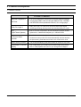
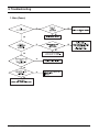
6. Troubleshooting
1. Main (Power)
Samsung Electronics
6-1
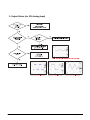
2. Output Failure (for 2Ch Analog Input)
6-2
Samsung Electronics
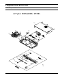
7.Exploded View & Parts List
1. Total Exploded View
AC080
AC025
AD510
AK290
AL180
AB030
AC010
AR011
AD502
AK170
AK250
AS260
AR011
AK420
AD370
7-1
Samsung Electronics
2. Parts List
LOC.
PART NAME
PART CODE
MATERAIL SPEC
Q'TY
AK250
KNOB-MIC
AH64-03687B
ABS
2
AD502
DOOR-DVD
AH64-04017A
ABS
1
AR011
RUBBER-FOOT
AH73-00005A
RUBBER
2
AB030
BADGE-BRAND
AH64-03746A
AL
1
AC010
CABINET-FRONT
AH64-04014A
HIPS
1
SNA
AL180
LENS-STAND BY
AH67-00438A
PMMA
1
SNA
AK290
KNOB-POWER
AH64-04016A
ABS
1
SNA
AS260
SPRING-DOOR
AH61-02122B
SUS304
1
AK420
KNOB-VOL
AH64-04030A
ABS
1
SNA
AD370
DECO-VOL
AH64-03789A
PC
2
SNA
AK170
KNOB-FUNCTION
AH64-04015A
ABS
1
SNA
AC025
CABINET-BOTTOM
AH64-04012A
SECC 0.6T
1
AD510
DOOR-TRAY
AH64-02320B
ABS
1
-
HOLDER-MECHA
AH61-02182A
ABS
1
-
HOLDER-VFD
AH61-02181A
ABS
1
-
HOLDER-IC
AH61-02183A
ABS+GF30%
1
-
H-SINK AMP
AH62-00146B
AL
1
AC080
CABINET-TOP
AH64-04013A
SECC 0.5T
1
A
TAPTITE SCREW
6003-001499
BWH 3*10 SILVER
3
B
TAPTITE SCREW
6003-001561
BH 3 *6 YEL
2
C
TAPTITE SCREW
6003-000280
BH 3*25 YEL
4
D
TAPTITE SCREW
6003-000275
BH 3*10 BLACK
3
Samsung Electronics
REMARK
SNA
7-2
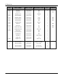
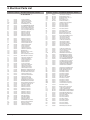
8. Electrical Parts List
Location no.
Code no.
Description & Specification Remarks
*** HT-Q9 Parts List ***
AC2
AC23
AC7
ACR24
AD510
2401-000651
2203-002398
2203-000626
2007-000081
AH64-02320A
C-AL;2.2uF,20%,50V,GP,TP,4x7,5
C-CER,CHIP;22nF,10%,50V,X7R,1608
C-CER,CHIP;0.022nF,5%,50V,C0G,1608
R-CHIP;2.7Kohm,5%,1/10W,TP,1608
DOOR-TRAY;HT-DB300,ABS,-,-,-,-,NTR,-
ADIC3
AIC2
AIC3
AIC4
AIC5
1002-001392
1201-002342
1204-002548
0801-002455
0801-001055
IC-A/D CONVERTER;WM8775EDS,24BIT,SSOP,28
IC-AUDIO AMP;S1S4001,SSOPH,56P,18.4x7.5m
IC-MODULATOR;S5M0061,TQFP,64P,10x10mm,PL
IC-CMOS LOGIC;74LV74,DUAL D F/F,TSSOP,14
IC-CMOS LOGIC;74VHC08,AND GATE,SOP,14,15
AR1
AR11
AR15
AR3
AR33
2007-000130
2007-000309
2007-000072
2007-000086
2007-000102
R-CHIP;39Kohm,5%,1/10W,TP,1608
R-CHIP;10ohm,5%,1/10W,TP,1608
R-CHIP;47ohm,5%,1/10W,TP,1608
R-CHIP;5.6Kohm,5%,1/10W,TP,1608
R-CHIP;100Kohm,5%,1/10W,TP,1608
AR34
AR8
C1P
C1S
C2P
2007-000121
2007-000091
2203-000257
2305-000412
2401-000847
R-CHIP;820ohm,5%,1/10W,TP,1608
R-CHIP;12Kohm,5%,1/10W,TP,1608
C-CER,CHIP;10nF,10%,50V,X7R,1608
C-FILM,LEAD-PEF;470nF,5%,63V,TP,-,5mm
C-AL;220uF,20%,35V,GP,TP,10x12mm,5m
C2RR
C37
C3A
C3S
C4P
2203-000783
2401-001508
2401-000414
2203-000260
2203-001537
C-CER,CHIP;0.33nF,5%,50V,C0G,1608
C-AL;47uF,20%,16V,GP,TP,6.3x5,5
C-AL;10uF,20%,16V,GP,TP,4x7,5
C-CER,CHIP;10nF,10%,50V,X7R,2012
C-CER,CHIP;1nF,10%,50V,X7R,TP,2012
CD000
CD300
CD340
CD380
CD520
AH61-01741A
AH66-00217A
AH66-00262A
AH66-00215A
3409-001138
BASE-MAIN;K100,ABS,-,-,-,-,GEAR-TRAY;CMS-SD100,POM,-,-,-,BLACK,-,-,
LEVER-LIFT;-,ABS,-,-,-,-,BLK,PULLEY MOTOR;CMS-SD100,POM,-,WHITE,-,-,SWITCH-DETECTOR;5V DC,1A,DPST,30GF,-
CK1
CK11
CK14
CK16
CK19
2402-000008
2203-000716
2401-001952
2401-000480
2401-000918
C-AL,SMD;47uF,20%,16V,GP,TP,6.6x6.6x5.4
C-CER,CHIP;3.3nF,10%,50V,X7R,2012
C-AL;4.7uF,20%,50V,GP,TP,5x7mm,5mm
C-AL;10uF,20%,50V,GP,TP,5x11,5
C-AL;22uF,20%,16V,GP,-,6.3x7,5
CK21
CK23
CK26
CK7
CK9
2401-001887
2402-000130
2203-000595
2203-005550
2203-001058
C-AL;0.1uF,20%,50V,-,TP,4x7mm,5
C-AL,SMD;2.2uF,20%,50V,GP,TP,4.3x4.3x5.
C-CER,CHIP;0.22nF,5%,50V,C0G,2012
C-CER,CHIP;82nF,10%,50V,X7R,TP,2012,C-CER,CHIP;0.56NF,5%,50V,C0G,TP,2012
CN1
CNP1
CNP1CP11
CP18
3711-000483
3711-000471
AH39-00754A
2401-001102
2402-001198
HEADER-BOARD TO CABLE;BOX,5P,1R,2mm,STRA
HEADER-BOARD TO CABLE;3WALL,4P,1R,2mm,ST
LEAD CONNECTOR;HT-P50,4P,2mm,70mm,1007#2
C-AL;330uF,20%,16V,GP,TP,8x11.5mm,5
C-AL,SMD;330UF,20%,6.3V,GP,TP,6.6X6.6X7
CP20
DC18
DC30
DD1
DD2
2401-001364
2203-005148
2203-000189
0407-000116
0403-001062
C-AL;470uF,20%,16V,GP,TP,10x12.5,5
C-CER,CHIP;100nF,10%,16V,X7R,1608
C-CER,CHIP;100nF,+80-20%,25V,Y5V,1608
DIODE-ARRAY;DAP202K,80V,100mA,CK2-3,SOTDIODE-ZENER;UDZ4.7B,4.55-4.75V,200MW,SOD
DDA1
DIC2
DR27
DR28
DR281
0404-000156
1201-001842
2007-000124
2007-000109
2007-000075
DIODE-SCHOTTKY;RB441Q,40V,350MA,DO-34,TP
IC-OP AMP;TL3472CD,SO,TP,8P,-,DUAL,-,PAL
R-CHIP;2.2Kohm,5%,1/10W,TP,1608
R-CHIP;1Mohm,5%,1/10W,TP,1608
R-CHIP;220ohm,5%,1/10W,TP,1608
DR29
DR30
DR31
DR55
DR57
2007-000120
2007-000090
2007-000458
2007-000134
2007-000082
R-CHIP;680ohm,5%,1/10W,TP,1608
R-CHIP;10Kohm,5%,1/10W,TP,1608
R-CHIP;18Kohm,5%,1/10W,TP,1608
R-CHIP;33Kohm,5%,1/10W,TP,1608
R-CHIP;3.3Kohm,5%,1/10W,TP,1608
DR64
EJACK
ER1
ER2
FL1
2007-000483
3722-000363
2007-000682
2007-000931
AH07-00190A
R-CHIP;1OHM,5%,1/8W,TP,2012
JACK-PHONE;9P,AU,BLK,ANGLE
R-CHIP;3.3Kohm,1%,1/8W,TP,2012
R-CHIP;470ohm,5%,1/8W,TP,2012
VF DISPLAY;HNV-08SS71,HT-Q9,75x18.5x6.8,
FS01
FUSEC
HC20
HC23
3404-000165
3602-000147
2203-001640
2203-000315
SWITCH-TACT;12V,50mA,160gf,6x6mm,SPST
FUSE-CLIP;250V,7.5A,30mohm
C-CER,CHIP;0.39nF,10%,50V,X7R,1608
C-CER,CHIP;0.12nF,5%,50V,C0G,1608
Samsung Electronics
Location no.
Code no.
Description & Specification Remarks
HC26
2203-001052
C-CER,CHIP;0.56nF,10%,50V,X7R,TP,1608
HEATS
HEATS
HEATS
HL23
IC HO
AH62-00062G
AH62-00146B
AH62-30061F
2703-001254
AH61-02183A
HEAT SINK-TR;HT-DS400,AL EXTR,-,-,-,-,-,
HEAT SINK-AMP;COMMON,AL,.,38,62,-,-,-,36
HEAT SINK-TR;-,AL,-,15,40,-,-,-,INDUCTOR-SMD;1.8uH,10%,2012
HOLDER-IC;HT-Q9,ABS+GF30%,-,-,-,-,-
KIC2
KR1
KR2
KR3
KR4
1201-001572
2007-001198
2007-000468
2007-000221
2007-000241
IC-PREAMP;2011,SIP,8P,19.2x6.5mm,SINGLE,
R-CHIP;820ohm,1%,1/8W,TP,2012
R-CHIP;1Kohm,5%,1/8W,TP,2012
R-CHIP;1.2Kohm,5%,1/8W,TP,2012
R-CHIP;1.5Kohm,5%,1/8W,TP,2012
KR5
KR6
L1SS
L2P
L5P
2007-000267
2007-000493
2702-001028
3301-000297
3301-000314
R-CHIP;1.8Kohm,5%,1/8W,TP,2012
R-CHIP;2.2Kohm,5%,1/8W,TP,2012
INDUCTOR-RADIAL;22UH,10%,10.3X18MM
BEAD-AXIAL;25ohm,3.6x1.2x5.7mm,-,TP,-,-,
BEAD-SMD;120ohm,1.6x0.8x0.8mm,150mA,,,,
LD1
MC10
MC16
MC18
MC29
0601-001238
2203-000815
2203-000972
2203-000998
2402-001009
LED;LTL-1CHESS-UA,ROUND,RED,3.1mm,697nm
C-CER,CHIP;0.033nF,5%,50V,C0G,1608
C-CER,CHIP;47nF,10%,16V,X7R,1608
C-CER,CHIP;0.047nF,5%,50V,C0G,1608
C-AL,SMD;100uF,20%,6.3V,GP,TP,5.3x5.3x5
MC31
MC40
MC43
MC45
MC5
2203-001656
2203-001103
2203-000646
2203-000440
2203-005221
C-CER,CHIP;0.47nF,5%,50V,NP0,1608
C-CER,CHIP;6.8nF,10%,50V,X7R,1608
C-CER,CHIP;0.024NF,5%,50V,C0G,TP,1608
C-CER,CHIP;1nF,10%,50V,X7R,1608
C-CER,CHIP;15nF,10%,50V,X7R,1608
MC50
MC52
MC53
MC6
MCON8
2402-001049
2203-005065
2401-000042
2203-006170
AH40-00129A
C-AL,SMD;10uF,20%,16V,GP,TP,3.3x3.3x5.4
C-CER,CHIP;1000nF,+80-20%,10V,Y5V,1608
C-AL;100uF,20%,16V,GP,TP,6.3x7,5
C-CER,CHIP;220nF,10%,16V,X7R,1608
TUNER;KST-MW004FV1-E50LKOR,HT-Q40,FM
MD3
MDIC1
MDIC2
MIC1
MIC1_
0403-000509
1003-001450
1003-001508
0801-002683
1002-001448
DIODE-ZENER;MTZJ5.6B,5.4-5.7V,500MW,DO-3
IC-MOTOR DRIVER;BA5954FM,SOP,28P,300MIL,
IC-MOTOR DRIVER;FAN8082DTF,SOP,8P,200MIL
IC-CMOS LOGIC;74HCT245,TRANSCEIVER,TSSOP
IC-A/D CONVERTER;AK5358ET,24,TSSOP,16P,5
MIC2
MIC3
MIC4
MIC6
MIC8
1204-002233
1107-001505
1204-002224
1103-001334
1105-001535
IC-VOLUME/TONE CONT.;PT2399S,SO,16P,300M
IC-FLASH MEMORY;49BV162AT,16Mbit,1Mx16/2
IC-PAL/NTSC DECODER;ES6698FD,PQFP,208P,2
IC-EEPROM;K524A60X81,1KX8BIT,SOP,8P,5X4M
IC-DRAM;M12L128168A-7T,-,128MBIT,4X2MX
MJ4
MQ1_1
MQ2
MR29
MR30
3708-002023
0504-000156
0504-000128
2007-000100
2007-000093
CONNECTOR-FPC/FFC/PIC;6P,1MM,SMD-S,TIN,N
TR-DIGITAL;KSR2103,PNP,200MW,22K/22K,SOT
TR-DIGITAL;-,NPN,200MW,22K/22K,SOT-23,TP
R-CHIP;68Kohm,5%,1/10W,TP,1608
R-CHIP;20Kohm,5%,1/10W,TP,1608
MR32
MR35
MR54
MR63
MR65
2007-000087
2007-000962
2007-000694
2011-000651
2007-000643
R-CHIP;6.8Kohm,5%,1/10W,TP,1608
R-CHIP;5.1Kohm,1%,1/10W,TP,1608
R-CHIP;3.3ohm,5%,1/8W,TP,2012
R-NET;10ohm,5%,1/16W,L,CHIP,8P,TP,32
R-CHIP;270ohm,5%,1/10W,TP,1608
MR66
MR93
MREG1
MREG2
MV1
2007-000077
2007-000118
1203-002425
1203-002935
2101-001068
R-CHIP;470ohm,5%,1/10W,TP,1608
R-CHIP;390ohm,5%,1/10W,TP,1608
IC-POSI.FIXED REG.;AP1117,SOT-223,3P,138
IC-POSI.ADJUST REG.;AIC1117ACE,TO-252,3P
VR-ROTARY;10KB,-,1/20W,SIDE
PB7
PC2
PC24
PS300
PS300
3301-001495
2402-001042
2401-001975
AH59-01687C
AH59-01731C
BEAD-SMD;120ohm,2012,2500mA,TP,115ohm/1
C-AL,SMD;100uF,20%,16V,GP,TP,6.6x6.6x5.
C-AL;47uF,20%,16V,GP,TP,5x11mm,5mm
SPEAKER SYSTEM;PS-Q9,XSH,FRONT,REAR,CENT
SPEAKER SYSTEM;PS-Q9,XSH,SUB W/F SPEAKER
Q4
Q5
R1P
R24
R2P
0501-000303
0501-000369
2007-000502
2007-000116
2007-001806
TR-SMALL SIGNAL;KSA733,PNP,250mW,TO-92,T
TR-SMALL SIGNAL;KSC2331-Y,NPN,1000mW,TOR-CHIP;2.2ohm,5%,1/8W,TP,2012
R-CHIP;120ohm,5%,1/10W,TP,1608
R-CHIP;1.5ohm,5%,1/10W,BK,1608
R2RR
R39
R3RR
R5SS
R7FL
2007-000462
2007-000094
2007-000518
2007-000253
2007-000695
R-CHIP;18ohm,5%,1/8W,TP,2012
R-CHIP;22Kohm,5%,1/10W,TP,1608
R-CHIP;2.7Kohm,5%,1/8W,TP,2012
R-CHIP;1.5ohm,5%,1/4W,TP,3216
R-CHIP;3.3ohm,5%,1/10W,TP,1608
RAC1
2003-000587
R-METAL OXIDE(S);22ohm,5%,1W,AA,TP,3.3x9
8-1
Location no.
Code no.
Description & Specification Remarks
Location no.
Code no.
Description & Specification Remarks
RAU2
RC1
RC10
RC15
2007-000119
2203-000681
2203-000491
2203-001222
R-CHIP;560ohm,5%,1/10W,TP,1608
C-CER,CHIP;0.027nF,5%,50V,C0G,1608
C-CER,CHIP;2.2nF,10%,50V,X7R,1608
C-CER,CHIP;0.82nF,10%,50V,X7R,1608
SMR49
SMR51
SMR62
SMR64
2007-000781
2001-000440
2007-000457
2007-000290
R-CHIP;33ohm,5%,1/8W,TP,2012
R-CARBON;1OHM,5%,1/8W,AA,TP,1.8X3.2MM
R-CHIP;18Kohm,5%,1/8W,TP,2012
R-CHIP;100ohm,5%,1/8W,TP,2012
RC2
RC25
RC27
RC31
RC40
2203-000888
2203-000357
2203-000575
2203-000975
2203-001634
C-CER,CHIP;4.7nF,10%,50V,X7R,1608
C-CER,CHIP;0.15nF,5%,50V,C0G,1608
C-CER,CHIP;220nF,10%,25V,X7R,2012
C-CER,CHIP;47nF,10%,25V,X7R,TP,1608,C-CER,CHIP;33nF,10%,50V,X7R,1608
SMR68
SMT01
SMT02
SMTH0
SMVR0
2007-000586
AH26-00338A
AH26-00337A
2006-001004
1405-000001
R-CHIP;22Kohm,5%,1/8W,TP,2012
TRANS POWER;-,HT-Q9,1.2mH,15,-,VARIABLE,
TRANS POWER;EER2828(PL-5,PM5),HT-Q9,620,
R-CEMENT;2.7OHM,5%,2W,CB,BK,11X20.5X7.5
VARISTOR;470V,1250A,14x7.5mm,TP
RC5
RCN1
REM1
REN1
RFG1
2402-000167
3708-001765
0609-001198
3406-001109
2007-000033
C-AL,SMD;100uF,20%,10V,-,-,6.6x6.6x5.7m
CONNECTOR-FPC/FFC/PIC;24P,0.5mm,SMD-S,SN
MODULE REMOCON;VERTICAL,19MM,TR
SWITCH-ROTARY;5V,0.5mA,SPDT,12mm
R-CHIP;0ohm,5%,1/4W,TP,3216
SMZD0
SPK1
UC12
UC16
UC18
0403-001170
3716-001243
2401-000240
2203-000206
2203-000236
DIODE-ZENER;MTZJ9.1C,8.89-9.29V,500MW,DO
TERMINAL-BLOCK;-,12P,14mm,-,C-AL;100uF,20%,10V,GP,TP,5x11,5
C-CER,CHIP;100nF,10%,50V,X7R,2012
C-CER,CHIP;0.1nF,5%,50V,C0G,1608
RG3
RIC1
RK1
RK12
RK14
2007-000300
1201-002059
2007-001071
2007-000029
2007-000981
R-CHIP;10Kohm,5%,1/8W,TP,2012
IC-RF AMP;ES6603SF,LQFP,64P,10X10MM,SING
R-CHIP;6.8Kohm,5%,1/8W,TP,2012
R-CHIP;0ohm,5%,1/8W,TP,2012
R-CHIP;5.6Kohm,5%,1/8W,TP,2012
UC2
UC6
UC8
UD10
UIC1
2401-000759
2409-000123
2203-005249
0401-001090
AH09-00111A
C-AL;220nF,20%,50V,GP,TP,5x11mm,5mm
C-EDL;47000uF,4uA,5.5V,-,BK,-,5mm
C-CER,CHIP;100nF,10%,50V,X7R,1608
DIODE-SWITCHING;1SS355,80V,100MA,SOD-323
IC MICOM;GMS87C2020,HT-Q9,64PIN,2.7V~5.
RK17
RK20
RK21
RK23
RK37
2007-000766
2007-000477
2007-000123
2007-000822
2007-000872
R-CHIP;330ohm,5%,1/8W,TP,2012
R-CHIP;1Mohm,5%,1/8W,TP,2012
R-CHIP;1.5Kohm,5%,1/10W,TP,1608
R-CHIP;390ohm,5%,1/8W,TP,2012
R-CHIP;4.7Kohm,5%,1/8W,TP,2012
UQ1
UR11
UR12
UR17
UR19
0501-000341
2007-000065
2007-000402
2007-000084
2007-000052
TR-SMALL SIGNAL;KSC1623-L,NPN,200mW,SOTR-CHIP;2.2Mohm,5%,1/10W,TP,1608
R-CHIP;150ohm,5%,1/10W,TP,1608
R-CHIP;4.7Kohm,5%,1/10W,TP,1608
R-CHIP;10Kohm,1%,1/10W,TP,1608
RK5
RK8
RL2
RP16
RPW6
2007-001177
2007-000409
3301-001069
2007-000824
2007-000113
R-CHIP;8.2Kohm,5%,1/8W,TP,2012
R-CHIP;15Kohm,5%,1/8W,TP,2012
BEAD-SMD;120ohm,1.6x0.8x0.8mm,200mA,TP,
R-CHIP;390ohm,5%,1/4W,TP,3216
R-CHIP;33ohm,5%,1/10W,TP,1608
UR24
UR46
UR51
UR6
UR9
2007-000074
2007-000106
2007-000449
2007-000070
2007-000078
R-CHIP;100ohm,5%,1/10W,TP,1608
R-CHIP;220Kohm,5%,1/10W,TP,1608
R-CHIP;180ohm,5%,1/8W,TP,2012
R-CHIP;0ohm,5%,1/10W,TP,1608
R-CHIP;1Kohm,5%,1/10W,TP,1608
RQ5
RR17
RR34
RR6
RR9
0501-000632
2007-000097
2007-000071
2007-000308
2007-000122
TR-SMALL SIGNAL;2SB1197K,PNP,200mW,SOT-2
R-CHIP;47Kohm,5%,1/10W,TP,1608
R-CHIP;22ohm,5%,1/10W,TP,1608
R-CHIP;10ohm,5%,1/8W,TP,2012
R-CHIP;1.2Kohm,5%,1/10W,TP,1608
UX1
VC2
VC38
VC49
VFD H
2802-000188
2401-000303
2401-001092
2203-000280
AH61-02181A
RESONATOR-CERAMIC;8MHz,0.5%,TP,10.0x5.0x
C-AL;100uF,20%,25V,GP,TP,6.3x11,5
C-AL;330uF,20%,10V,GP,-,8x11.5,2.5m
C-CER,CHIP;0.01nF,0.5pF,50V,C0G,1608
HOLDER-VFD;HT-Q9,ABS,-,-,-,-,-
SMBC0
SMBD0
SMC01
SMC03
SMC04
AC27-92001M
0402-000003
2201-000987
2201-002213
2401-003472
COIL-INDUCTOR;RH3.5X6.5RS,BEAD(RADIAL),DIODE-BRIDGE;DF06M,600V,1A,DIP-4,ST
C-CERAMIC,DISC;2.2NF,20%,400V,Y5U,BK,12.
C-CERAMIC,DISC;0.47nF,10%,400V,Y,-,9.5X7
C-AL;100UF,20%,250V,GP,BK,16X31.5MM
VJ5
VL29
VQ3
VR17
VR51
3722-002027
2703-000272
0501-000002
2007-000076
2007-001134
JACK-PIN;6P/6C,SN,YEL/GN/WH/BL/RD,ANGLE
INDUCTOR-SMD;1.2uH,10%,2012
TR-SMALL SIGNAL;KSA812,PNP,150MW,SOT-23,
R-CHIP;330ohm,5%,1/10W,TP,1608
R-CHIP;68ohm,5%,1/10W,TP,1608
SMC08
SMC09
SMC10
SMC11
SMC16
2301-000474
2301-000449
2401-002300
2301-000375
2305-001016
C-FILM,LEAD-PEF;8.2nF,10%,50V,TP,6.5x12x
C-FILM,LEAD-PEF;47nF,10%,50V,TP,9.5x12.5
C-AL;47uF,20%,50V,GP,TP,6.3x11,5
C-FILM,LEAD-PEF;100nF,5%,50V,TP,11x12.5x
C-FILM,LEAD-PEF;10nF,10%,630V,TP,12.5x6.
VR56
VR7
WC5
WC9
X2
2007-001167
2007-000115
2401-002042
2203-000727
2801-004284
R-CHIP;75ohm,5%,1/10W,TP,1608
R-CHIP;82ohm,5%,1/10W,TP,1608
C-AL;220uF,20%,10V,GP,TP,6.3x11,5
C-CER,CHIP;3.9nF,10%,50V,X7R,2012
CRYSTAL-SMD;27MHZ,10PPM,28-AAN,20PF,30OH
SMC18
SMC41
SMC43
SMC44
SMC46
2201-000551
2401-003139
2401-003378
2401-001020
2401-000357
C-CERAMIC,DISC;0.47NF,10%,1KV,Y5P,TP,6.3
C-AL;1000uF,20%,25V,WT,TP,10*20,5mm
C-AL;1000uF,20%,10V,WT,-,10x12.5,5
C-AL;3.3UF,20%,50V,GP,TP,4X7,5
C-AL;100uF,20%,50V,GP,-,8x11.5,3.5m
XD9
ZD5
0401-001099
0403-000355
3101-001300
AH59-01592A
3301-001760
DIODE-SWITCHING;1N4148WS,75V,150mA,SOD-3
DIODE-ZENER;UZ5.1BSB,5-5.2V,500MW,DO-35,
MOTOR-DC;2670RPM,9G.CM,3.9V,160MA
DECK-CD;-,CMS-S75RB,MAGNET,23.2mm,3V,S
CORE-FERRITE;-,33x12x8mm,-,-
SMC48
SMC49
SMC50
SMC60
SMC61
2401-000804
2401-001355
2401-000118
2201-000129
2401-000740
C-AL;220uF,20%,16V,GP,TP,8x9mm,5
C-AL;470uF,20%,10V,GP,TP,8x11.5mm,5
C-AL;1000uF,20%,10V,GP,TP,10x12.5,5
C-CERAMIC,DISC;0.1nF,10%,1000V,Y5P,-,7x4
C-AL;2200uF,20%,50V,LZ,TP,18x40,7.5
3809-001627
3809-001630
AH39-00884A
AH61-01742A
AH61-01743A
CABLE-FLAT;30V,80C,90mm,6P,1mm,UL20696
CABLE-FLAT;30V,80C,175mm,24P,0.5mm,UL206
LEAD CONNECTOR-ASSY;SDM-D12,-,-,5P,150mm
BODY CLAMPER-UPPER;-,POM,0.8,-,-,-,WHT,BODY CLAMPER-LOWER;-,POM,0.8,-,-,-,WHT,-
SMC64
SMCM0
SMD02
SMD04
SMD41
2401-000598
2301-001220
0402-001148
0402-000012
0402-001377
C-AL;1uF,20%,50V,GP,TP,4x7,5
C-FILM,LEAD-PPF;100nF,10%,275V,BK,18x6x1
DIODE-RECTIFIER;1N4936,400V,1.0A,DO-41,T
DIODE-RECTIFIER;UF4007,1KV,1A,DO-41,TP
DIODE-RECTIFIER;UG4D,200V,4A,TO-220F,TP
AH63-00695A
AH63-00905A
AH66-00261A
AH73-00058A
AH61-02182A
TRAY-DISK;SDM-D11,ABS,-,-,-,-,GRAY,FELT-DECK;SDM-D12,FELT,0.8,10,18,-,DOUBL
CAM-SLIDE;K100,POM,-,-,WHT,-,-,-,SILICON/RUBBER-DECK;CMS-SD100,SILICON,D1
HOLDER-MEHCA;HT-Q9,ABS,-,-,-,-,-
SMD43
SMD50
SMFU0
SMIC0
SMIC0
0402-000268
0401-000005
3601-000301
1203-003336
1203-004084
DIODE-RECTIFIER;SB360,60V,3A,DO-201AD,TP
DIODE-SWITCHING;1N4148,75V,150mA,DO-35,T
FUSE-CARTRIDGE;250V,6.3A,TIME-LAG,GLASS,
IC-PWM CONTROLLER;KA5M0365,TO-220F-4L,4P
IC-PWM CONTROLLER;FSDM0365RNB,DIP,8P,9.8
3301-000132
6902-000360
AH39-00257J
AH39-40001V
AH42-00021A
CORE-FERRITE;AC,28.8x19.3x7.5mm,1400,290
BAG PE;HDPE,T0.03,L360,W250,TRP,8,1,P
CBF-POWER CORD;DVC90,-,CP2(5.0),250V,2.5
CABLE-AUDIO CABLE;-,-,1P-1P,3000MM,-,-,ANT FM T;T18011F-1,75 ohm,1800mm
SMIC4
SMIC4
SMIC4
SMIC4
SMIC4
1203-000294
1203-001586
1203-001589
1203-000165
AC14-12006D
IC-POSI.FIXED REG.;7808,TO-220,3P,-,PLAS
IC-POSI.FIXED REG.;278R33,TO-220F,4P,-,P
IC-POSI.FIXED REG.;278R05,TO-220F,4P,-,P
IC-POSI.ADJUST REG.;78R12,TO-220,4P,-,PL
IC;KA431Z,TO-92,TAPING
AH59-01615E
AH59-01657A
AH92-02518C
DECK-1DVD MECHA;AH59-01615E,HT-Q20,T TYP
REMOCON-ASSY;HT-Q9,SAMSUNG,50,200,-,60,ASSY PCB-MAIN3;HT-Q9/XEU,MAIN,ENGLAND
SMLF0
SMPC0
SMPN0
SMQ01
SMR01
AH29-00013A
0604-000117
3711-000190
0501-000630
2001-000242
FILTER LINE;HT-Q9,SQE-2424(SM100S,HM5A,PHOTO-COUPLER;TR,130-260%,200mW,DIP-4,ST
HEADER-BOARD TO CABLE;1WALL,2P,1R,7.92MM
TR-SMALL SIGNAL;KTA1268,PNP,300MW,TO-92,
R-CARBON;1.5MOHM,5%,1/4W,AA,TP,2.4X6.4M
SMR04
SMR05
SMR08
SMR43
SMR44
2001-000302
2001-000786
2003-000738
2007-000830
2007-001043
R-CARBON;10OHM,5%,1/8W,AA,TP,1.8X3.2MM
R-CARBON;47KOHM,5%,1/8W,AA,TP,1.8X3.2MM
R-METAL OXIDE(S);56Kohm,5%,2W,AA,TP,4x12
R-CHIP;39Kohm,5%,1/8W,TP,2012
R-CHIP;56ohm,5%,1/8W,TP,2012
SMR46
2007-000030
R-CHIP;560ohm,5%,1/8W,TP,2012
8-2
Samsung Electronics
- This Document can be used without Samsung’s authorization -
9. BLOCK DIAGRAM
9-1. MAIN BLOCK DIAGRAM
1-1. MAIN
Samsung Electronics
9-1
- This Document can be used without Samsung’s authorization -
10. Wiring Diagram
1-1. MAIN
Samsung Electronics
10-1
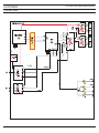
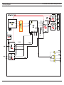
- This Document can be used without Samsung’s authorization -
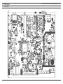
11. PCB Diagram
11-1. PCB Layout
1-1. MAIN
Samsung Electronics
11-1
- This Document can be used without Samsung’s authorization -
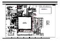
12. Schematic Diagram
1. MAIN-1
1-1. MAIN
Samsung Electronics
12-1
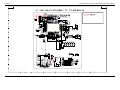
2. MAIN-2
12-2
- This Document can be used without Samsung’s authorization -
Samsung Electronics
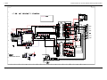
3. AMP
Samsung Electronics
- This Document can be used without Samsung’s authorization -
12-3
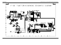
4. FUNCTION
12-4
- This Document can be used without Samsung’s authorization -
Samsung Electronics
5. RF
Samsung Electronics
- This Document can be used without Samsung’s authorization -
12-5
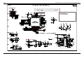
6. SMSP
12-6
- This Document can be used without Samsung’s authorization -
Samsung Electronics
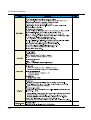
13. Circuit Description
1. Description (HT-Q9)
DECK
MPEG
TUNER
AMP
MAIN
SMPS
FRONT
Samsung Electronics
13-1
2. Function Description
13-2
Samsung Electronics
1. Definition of Home Theater
What is Home Theater?
Home theater system is the proper combination of audio and video system at home which enable
you to enjoy more dynamic sound and vivid image in a wide screen of movie theater.
This effect can be implemented with wide screen, high quality projector, Dolby digital and DTS
sound effects.
Now you can enjoy surround sound field wieh realistic presence and Dolby digital at your home as if
you are in a movie theater.
As time goes by, home theater system has become recognized as a system that helps listen sound
closer to the original sound rather than video. In this 21st century, most movie and animation films
will be produced for home theater and reproduce sound closer to original sound.
14-1
Samsung Electronics
2. Concept of Sound
What is Sound Range?
People can listen to the sounds with frequency between 200Hz~20.000Hz
As time goes by, home theater system has become recognized as a system that helps listen sound
closer to the original sound rather than video. In this 21st century, most movie and animation films
will be produced for home theater and reproduce sound closer to original sound.
What is Sound Pressure?
* A measure of how well speaker converts electric signal it receives to sound
* Unit of sound pressure is decibel and mainly measures the size of sound at 1 m away after
sending 1 W power from speaker.
❋ High sound pressure doesn't necessary mean good performance
What is Timbre?
* How well the unique sound of musical instrument is expressed
* Better if violin and cello sound are accurately distinguished. Good timbre means high quality.
Samsung Electronics
14-2
2. Concept of Sound
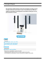
By reproducing standard channels used during soundtrack recording of movie,
it outputs 3 sounds of movie (words / music / sound effects) from 6 different
speakers and provides surround dynamic sound effects so that you can even
feel the direction of sound.
5 channel
A
Center Speaker : Voice ( over 95%)
B
Front Speaker (L/R) : Music Sound
C
Rear Speaker (L/R) : Sound Effect
0.1 channel
D
Subwoofer : Low Sound Effect
* Power amp is embedded in active sub woofer
* Require separate amp since there is no amp in passive sub woofer
❋ No difference in performance of active sub woofer and passive sub woofer
14-3
Samsung Electronics
4. Home Theater Sound Format
Overview
* As home theater has recently penetrated deep into consumer's market in Korea, Dolby digital and
DTS, the sound format for 5.1 channel home theater, are the mainstream in the market.
* Expanded type of 6.1 channel or 7.1 channel are recently released in the market, but there are
not much DVD title that can support expanded type.
1958 1Ch Mono/ 2Ch Stereo
1982 Matrix 3Ch Dolby Surround
1987 Matrix 4Ch Dolby Pro Logic
1995 5.1Ch Dolby Digital
1997 DTS (Digital Theater System)
1999 Matrix 6.1Ch Dolby Digital Sourround EX
Home theater format...
Stereo
Is used in general audio and analog TV and and consists of 2
channels, at front left/right
Dolby Surround
In this sound format, 4 audio channels (Front left / right / center /
surround) are entered in 2 channel and reproduce in 4 channels
through device with Dolby decoder.
Center channel is not completely separated so that it forms virtual
center channel with help of front left / right channel.
Samsung Electronics
14-4
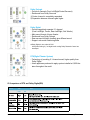
Dolby Prologic
– Provide 4 channels (Front Left/Right/Center/Surround)
– Reinforced from Dolby Surround
① Center channel is completely separated
➁ Separation between channels gets higher
Dolby Digital
– Provide completely separate 5.1 channel
(Front Left/Right, Center, Rear Left/Right, Sub Woofer)
– Main sound format of home theater
– Reinforced from Dolby Prologic
– Rear surround left/right channels give different sound
– Support sub woofer reinforcing Bass
❋ Dolby Digital is also called AC-301
AC-3(Audo-Coding-3) : 3rd digital audio coding Dolby Research Center has
developed.
DTS(Digital Theater System)
– Technology of providing 5.1 channel sound, higher quality than
Dolby Digital
– Home appliance produced to apply system installed at 1,800 theaters throughout the world.
✪ Comparison of DTS and Dolby Digital(DD)
14-5
Samsung Electronics
Dolby Prologic
– Latest technology reproducing music CD recorded in 2 channel,
cassette tape and video tape made in Dolby Prologic into 5.1
channel.
– Surround speaker that makes you feel more natural, deeper and
wider than existing Dolby Prologic.
(Ex-Profound sound adds more realistic presence from 5 speakers
and sub woofer when you watch soccer match.)
DTS (Digital Theater System)
THX (Abbreviation of Tomlison Holman's Experiment)
– THX is not a sound format like a Dolby or DTS, but is a standard of sound. Like standard KS mark
in Korea, THX means good certification in sound effects.
– THX issues certificate when a movie, theater or home theater system satisfy proper standards.
Samsung Electronics
14-6
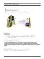
5. Home Theater Components
Amp / Receiver
Amp: Device of raising output after tuning signal of CD player or DVD into
unique sound timbre
Various Types and Usages of Amplifier
- For Listening to Music ¡æ For Music+ Movie
- ① AV Receiver (Dedicated Lamp for Home Theater) : Preferred by Home Theater mania.
➁ DVD Receiver (DVD Player+ Amp+ Radio Tuner) : Suitable for beginner of Home Theater
- Many A/V companies adopt DVD receiver type for expansion of easy and economic Home Theater
system.
Popular Korean Products
- Popular for those who pursue relatively good sound quality at low price
- Product priced between 400,000 won~600,000 won are popular.
14-7
Samsung Electronics
Popular Foreign Products
– Popular for those who prefer profound sound volume/output(Hi-fi mania, Home Theater mania)
– Products in the range of middle and low price such as Denon, Yamaha, Onkyo (900,000~1.1 million won) are popular.
– There is very expensive product over 10 million won among foreign audio markers such as
Merdian, Mcintosh, Krell.
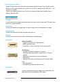
Type of Amp/Receiver
* Pre Amp
A device that receives, adjusts and sends signal from source devices (tape deck, CD player, radio
tuner, etc.) to power amplifier.
* Power Amp
A device that amplifies the signal from Pre Amp into big sound so that speaker can vibrate.
* Integrated Amp
A device that combines pre-amp and power amp into one.
* Receiver
A device that contains tuner for radio broadcasting and integrated amp.
A/V Receiver
General Amplifier
– Support 2 channels (Left, Right Speaker)
– Mainly reproduce music
– No decoder : cannot cope with various sound formats
A/V Receiver
– Support multi-channel (support 5.1 channel)
Launch products supporting 6.1 channel and 7.1 channel
recently.
– Reproduce music and movie sound realistically
– Has decoder
Can cope with various sound formats such as Dolby Digital.
DTS
– Rich input/output
– Use digital signal type and has no sound
A/V Receiver
A device of implementing home theater more conveniently with
radio and A/V receiver embeded in DVD player.
Samsung Electronics
14-8
How to Select Amp/Receiver
- Select the products that can support both Dolby Digital and DTS since they require both for vivid
sound
- Performance of amp gets better in output(W) but high output is a burden in narrow house.
- Important to match output(W) and capacity(§Ù) of amp and speaker.
- It is advantageous for beginners to purchase DVD receiver type that has amp and radio tuner in
DVD player
- If the budget is tight, it is recommended to continue to upgrade after purchasing a low-priced system.
* Computer will be of no use when it is outdated.
* But, home theater system can be utilized in various ways due to feature of A/V device.
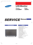
Speaker
Speaker system consists of speaker unit and enclosure.
The type and price range are diverse from expensive big speaker to miniature thin speaker.
Difference between famous speaker and big A/V speaker
- Speaker units are similar(there are a few several speaker unit makers in the world)
- Design, finishing, assembling and tuning process of enclosure are different.
(Prestige speakers are made manually in whole processes of manufacturing)
Famous speaker brands: B&W, JBL, BOSE, Definitve, B&O, etc.
14-9
Samsung Electronics
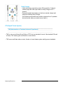
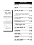
Speaker Structure
Speaker Unit
- Divided into for high tone, middle tone and low tong
- Tweeter : for high pitch
Smallest unit suitable for feature of high tone reproduction
- Mid-Range : for middle tone
Mid sound reproduction ability is the most critical standard
of speaker evaluation
- Woofer : for low tone
Much bigger size than other speaker unit
Enclosure
- Case of speaker unit
- Enclosure sways sound quality of reproduction
- Low tone is almost acattered without enclosure, and only
high sound tone is heard.
Type of Speaker System
Full Range Speaker
A speaker system producing sound with one speaker unit.
2 Way Type
A speaker system designed using units of 2 woofers for bass and tweeter for high tone.
3 Way Type
Difference between foreign prestige speaker and big A/V maker's speaker.
Samsung Electronics
14-10