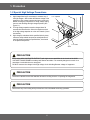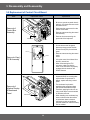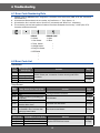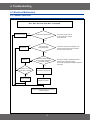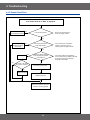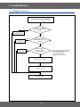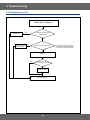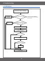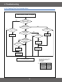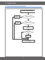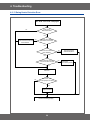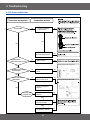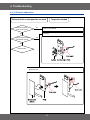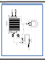
1
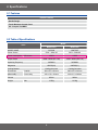
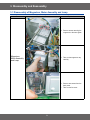
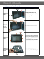
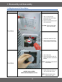
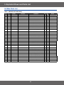
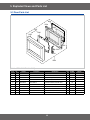
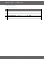
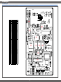
BASIC:
M1736N
MODEL:
MW73VR
MODEL CODE: MW73VR/BWT
1. Precaution
2. Product Specification
3. Disassembly and Reassembly
4. Troubleshooting
5. Exploded Views and Part List
6. PCB Diagrams
7. Wiring Diagrams
8. Schematic Diagrams
Refer to the service manual in the GSPN(see rear cover) for the more information.
• Contents
1. Precaution. . . . . . . . . . . . . . . . . . . . . . . . . . . . . . . . . . . . . . . . . . . . . . . . . . . . . . . . . . . . . . . . . . . . . . . . . . . . . . 3
1-1 Safety precautions. . . . . . . . . . . . . . . . . . . . . . . . . . . . . . . . . . . . . . . . . . . . . . . . . . . . . . . . . . . . . . . . . . . . . 4
1-2 Special High Voltage Precautions . . . . . . . . . . . . . . . . . . . . . . . . . . . . . . . . . . . . . . . . . . . . . . . . . . . . . . . . . 5
2. Specifications . . . . . . . . . . . . . . . . . . . . . . . . . . . . . . . . . . . . . . . . . . . . . . . . . . . . . . . . . . . . . . . . . . . . . . . . . . . 6
2-1 Features. . . . . . . . . . . . . . . . . . . . . . . . . . . . . . . . . . . . . . . . . . . . . . . . . . . . . . . . . . . . . . . . . . . . . . . . . . . . . 6
2-2 Table of Specifications. . . . . . . . . . . . . . . . . . . . . . . . . . . . . . . . . . . . . . . . . . . . . . . . . . . . . . . . . . . . . . . . . . 6
2-3 Accessory. . . . . . . . . . . . . . . . . . . . . . . . . . . . . . . . . . . . . . . . . . . . . . . . . . . . . . . . . . . . . . . . . . . . . . . . . . . . 7
3. Disassembly and Reassembly. . . . . . . . . . . . . . . . . . . . . . . . . . . . . . . . . . . . . . . . . . . . . . . . . . . . . . . . . . . . . . 8
3-1 Disassembly of Magnetron, Motor Assembly and Lamp . . . . . . . . . . . . . . . . . . . . . . . . . . . . . . . . . . . . . . . . 8
3-2 Replacement of High Voltage Trancefomer. . . . . . . . . . . . . . . . . . . . . . . . . . . . . . . . . . . . . . . . . . . . . . . . . 10
3-3 Replacement of Door Assembly. . . . . . . . . . . . . . . . . . . . . . . . . . . . . . . . . . . . . . . . . . . . . . . . . . . . . . . . . . 12
3-4 Replacement of Drive Motor . . . . . . . . . . . . . . . . . . . . . . . . . . . . . . . . . . . . . . . . . . . . . . . . . . . . . . . . . . . . 13
3-5 Replacement of Control Circuit Board. . . . . . . . . . . . . . . . . . . . . . . . . . . . . . . . . . . . . . . . . . . . . . . . . . . . . 14
4. Troubleshooting . . . . . . . . . . . . . . . . . . . . . . . . . . . . . . . . . . . . . . . . . . . . . . . . . . . . . . . . . . . . . . . . . . . . . . . . 15
4-1 Error Code Numbering Rule. . . . . . . . . . . . . . . . . . . . . . . . . . . . . . . . . . . . . . . . . . . . . . . . . . . . . . . . . . . . . 15
4-2 Error Code List. . . . . . . . . . . . . . . . . . . . . . . . . . . . . . . . . . . . . . . . . . . . . . . . . . . . . . . . . . . . . . . . . . . . . . . 15
4-3 Electrical Malfunction. . . . . . . . . . . . . . . . . . . . . . . . . . . . . . . . . . . . . . . . . . . . . . . . . . . . . . . . . . . . . . . . . . 17
5. Exploded Views and Parts List . . . . . . . . . . . . . . . . . . . . . . . . . . . . . . . . . . . . . . . . . . . . . . . . . . . . . . . . . . . . 33
5-1 Exploded Views. . . . . . . . . . . . . . . . . . . . . . . . . . . . . . . . . . . . . . . . . . . . . . . . . . . . . . . . . . . . . . . . . . . . . . 33
5-2 Main Parts List. . . . . . . . . . . . . . . . . . . . . . . . . . . . . . . . . . . . . . . . . . . . . . . . . . . . . . . . . . . . . . . . . . . . . . . 34
5-3 Door Parts List. . . . . . . . . . . . . . . . . . . . . . . . . . . . . . . . . . . . . . . . . . . . . . . . . . . . . . . . . . . . . . . . . . . . . . . 35
5-4 Control Parts List. . . . . . . . . . . . . . . . . . . . . . . . . . . . . . . . . . . . . . . . . . . . . . . . . . . . . . . . . . . . . . . . . . . . . 36
5-5 Standard Parts List. . . . . . . . . . . . . . . . . . . . . . . . . . . . . . . . . . . . . . . . . . . . . . . . . . . . . . . . . . . . . . . . . . . . 37
6. PCB Diagrams. . . . . . . . . . . . . . . . . . . . . . . . . . . . . . . . . . . . . . . . . . . . . . . . . . . . . . . . . . . . . . . . . . . . . . . . . . 38
6-1 PCB Diagrams. . . . . . . . . . . . . . . . . . . . . . . . . . . . . . . . . . . . . . . . . . . . . . . . . . . . . . . . . . . . . . . . . . . . . . . 38
7. Wiring Diagrams . . . . . . . . . . . . . . . . . . . . . . . . . . . . . . . . . . . . . . . . . . . . . . . . . . . . . . . . . . . . . . . . . . . . . . . . 39
7-1 Wiring Diagrams. . . . . . . . . . . . . . . . . . . . . . . . . . . . . . . . . . . . . . . . . . . . . . . . . . . . . . . . . . . . . . . . . . . . . . 39
8. Schematic Diagrams. . . . . . . . . . . . . . . . . . . . . . . . . . . . . . . . . . . . . . . . . . . . . . . . . . . . . . . . . . . . . . . . . . . . . 41
8-1 Schematic Diagrams . . . . . . . . . . . . . . . . . . . . . . . . . . . . . . . . . . . . . . . . . . . . . . . . . . . . . . . . . . . . . . . . . . 41
1. Precaution
1. Precaution
Follow these special safety precautions. Although the microwave oven is completely safe during ordinary use,
repair work can be extremely hazardous due to possible exposure to microwave radiation, as well as potentially
lethal high voltages and currents.
1-1 Safety precautions (
)
13. Design Alteration Warning: Use exact replacement
parts only, i.e.,only those that are specified in
thedrawings and parts lists of this manual. This
is especially important for the Interlock switches,
described above. Never alter or add to the
mechanical or electrical design of the MWO.
Any design changes or additions will void the
manufacturer’s warranty. Always unplug the unit’s
AC power cord from the AC power source before
attempting to remove or reinstall any component or
assembly.
14. Never defeat any of the B+ voltage interlocks. Do not
apply AC power to the unit (or any of its assemblies)
unless all solid-state heat sinks are correctly
installed.
15. Some semiconductor (“solid state”) devices
are easily damaged by static electricity. Such
components are called Electrostatically Sensitive
Devices (ESDs). Examples include integrated
circuits and field-effect transistors. Immediately
before handling any semiconductor components or
assemblies, drain the electrostatic charge from your
body by touching a known earth ground.
16. Always connect a test instrument’s ground lead to
the instrument chassis ground before connecting the
positive lead; always remove the instrument’s ground
lead last.
17. When checking the continuity of the witches or
transformer, always make sure that the power is
OFF, and one of the lead wires is disconnected.
18. Components that are critical for safety are indicated
in the circuit diagram by shading,
or
.
19. Use replacement components that have the same
ratings, especially for flame resistance and dielectric
strength specifications. A replacement part that does
not have the same safety characteristics as the
original might create shock, fire or other hazards.
NOTE : Connect the oven to a 20A. When
connecting the oven to a 15A,make sure that circuit
breaker can operate.
1. All repairs should be done in accordance with the
procedures described in this manual. This product
complies with Federal Performance Standard 21
CFR
2. Microwave emission check should be performed to
prior to servicing if the oven is operative.
3. If the oven operates with the door open :Instruct
the user not to operate the oven and contact
the manufacturer and the center for devices and
radiological health immediately.
4. Notify the Central Service Center if the microwave
leakage exceeds 5 mW/cm2.
5. Check all grounds.
6. Do not power the MWO from a “2-prong” AC cord.
Be sure that all of the built-in protective devices are
replaced. Restore any missing protective shields.
7. When reinstalling the chassis and its assemblies,
be sure to restore all protective devices, including:
nonmetallic control knobs and compartment covers.
8. Make sure that there are no cabinet openings
through which people --particularly children--might
insert objects and contact dangerous voltages.
Examples: Lamp hole,ventilation slots.
9. Inform the manufacturer of any oven foundto have
emission in excess of 5 mW/cm2 ,Make repairs to
bring the unit into compliance at no cost to owner
and try to determine cause. Instruct owner not to use
oven until it has been brought into compliance.
CENTRAL SERVICE CENTER
10. Service technicians should remove their watches
while repairing an MWO.
11. To avoid any possible radiation hazard,replace parts
in accordance with the wiring diagram. Also, use
only the exact replacements for the following parts:
Primary and secondary interlock switches, interlock
monitor switch.
12. If the fuse is blown by the Interlock Monitor Switch:
Replace all of the following at the same time:
Primary, door sensing switch and power relay, as
well as the Interlock Monitor Switch. The correct
adjustment of these switches is described elsewhere
in this manual. Make sure that the fuse has the
correct rating for the particular model being repaired.
1. Precaution
1-2 Special High Voltage Precautions
1. High Voltage Warning Do not attempt to measure any of
the high voltages --this includes the filament voltage of the
magnetron. High voltage is present during any cook cycle.
Before touching any components or wiring, always unplug
the oven and discharge the high voltage capacitor (See
Figure 1-1)
2. The high-voltage capacitor remains charged about 30
seconds after disconnection. Short the negative terminal
of the high-voltage capacitor to to the oven chassis. (Use a
screwdriver.)
3. High voltage is maintained within specified limits by closetolerance, safety-related components and adjustments. If
the high voltage exceeds the specified limits, check each
of the special components.
H . V . Capacitor
H . V . Diode
Short
PRECAUTION
There exists HIGH VOLTAGE ELECTRICITY with high current capabilities in the circuits of the HIGH
VOLTAGE TRANSFORMER secondary and filament terminals. It is extremely dangerous to work on or
near these circuits with the oven energized.
DO NOT measure the voltage in the high voltage circuit including filament voltage of magnetron.
PRECAUTION
Servicemen should remove their watches whenever working close to or replacing the magnetron.
PRECAUTION
Never touch any circuit wiring with your hand nor with uninsulated tool during operation.
2. Specifications
2-1 Features
Product Features
- Handle Design
- Tact & Menbrane Control Panel
- 20L Compact Size MWO
2-2 Table of Specifications
Items
Model
Model Basic
Model New
MODEL NAME
M1736N
MW73VR
Power Source
230V ~ 50Hz AC
230V ~ 50Hz AC
1300W
1150W
100W / 800W (IEC-705)
100W / 800W (IEC-705)
2450MHz
2450MHz
OM75S(31)
OM75S(31)
Cooling fan motor
Cooling fan motor
Outside
489 x 275 x 361mm
489 x 275 x 361mm
Oven cavity
306 x 211 x 320mm
306 x 211 x 320mm
20Liter
20Liter
12.5Kg
12.5Kg
Power consumption
Microwave
Output Power
Operating Frequency
Magnetron
Cooling Method
Dimensions
(W x H x D)
Volume
Weight
Net
2. Specifications
2-3 Accessory
Item
Description
Code No.
Q’ty
Coupler
DE67-00140A
1
Assy-Guide Roller
DE97-00193B
1
Tray-cooking
DE74-00027A
1
3. Disassembly and Reassembly
3-1 Disassembly of Magnetron, Motor Assembly and Lamp
Remove the magnetron including the shield case, permanent magnet, choke coils and capacitors (all of which
are contained in one assembly)
Parts
Explaination Photo
Explaination
1. Disconnect all lead wires from
the magnetron and lamp.
Magnetron,
Motor Assembly
and Lamp
2. Remove a screw securing air
cover.
3. Remove the air cover.
3. Disassembly and Reassembly
3-1 Disassembly of Magnetron, Motor Assembly and Lamp
Parts
Explaination Photo
Explaination
4. Remove screws securing the
magnetron to the wave guide.
Magnetron,
Motor Assembly
and Lamp
5. Take out the magnetron very
carefully.
6. Remove two screws from the
back panel.
7. Take out the fan motor.
3. Disassembly and Reassembly
3-1 Disassembly of Magnetron, Motor Assembly and Lamp
Parts
Explaination Photo
Magnetron,
Motor Assembly
and Lamp
Explaination
8. Remove the oven lamp from
hole of air cover.
NOTE1: When removing the magnetron, make sure that its antenna does not hit any adjacent parts, or it may be
damaged.
NOTE2: When replacing the magnetron, be sure to remount the magnetron gasket in the correct position and
make sure the gasket is in good condition.
3-2 Replacement of High Voltage Trancefomer
Parts
Explaination Photo
Explaination
1. Discharge the high voltage
capacitor.
High Voltage
Transformer
2. Disconnect all the leads.
10
3. Disassembly and Reassembly
3-2 Replacement of High Voltage Trancefomer
Parts
Explaination Photo
Explaination
3. Remove the mounting bolts.
High Voltage
Transformer
4. Replace the High Voltage
Transformer
5. After replace, reconnect the
leads correctly and firmly.
PRECAUTION
Servicemen should remove their watches whenever working close to or replacing the magnetron.
PRECAUTION
There exists HIGH VOLTAGE ELECTRICITY with high current capabilities in the circuits of the
HIGHVOLTAGE TRANSFORMER secondary and filament terminals. It is extremely dangerous to work on
or near these circuits with the oven energized.
DO NOT measure the voltage in the high voltage circuit including filament voltage of magnetron.
11
3. Disassembly and Reassembly
3-3 Replacement of Door Assembly
Parts
Disassembly Photo
Explaination
Removal of
Door “C”
Insert flat screwdriver into the gap
between Door “A” and Door “C” to remove
Door “C”. Be careful when handling Door
“C” because it is fragile.Then remove the
door assembly.
Removal
of Door
Assembly
Lift up the Door Assembly from Cavity.
Removal of
Door “E”
Following the procedure as shown in the
figure, insert and bend a thin metal plate
between Door “E” and Door “A” until you
hear the ‘tick’ sound.
• Insertion depth of the thin metal plate
should be 0.5mm or less.
Removal of
Key Door &
Spring
Remove pin hinge from Door “E”
Detach spring from Door “E” and key door.
12
3. Disassembly and Reassembly
3-4 Replacement of Drive Motor
Parts
Explaination Photo
Explaination
1. Take out the glass tray,
guide roller from oven cavity,
disconnect power.
2. Remove turn table motor cover
from case bottom.
CAUTION : Remove sharp edge
after cover removal.
Drive Motor
3. Disconnect leads from motor.
4. Remove the screws securing
motor to bottom of over cavity.
6. Lift out the motor.
5. When replacing the motor, be
sure to remount it in the correct
position.
NOTE : The shaft of motor should
fit tip coupler.
Drive Motor
COVER FIXING SCREW :
MATCHINE SCREW(6006-001170)
13
6. When reassemble a drive
motor cover. give a turn in a
180° and fix with a screw.
NOTE : Bring the spare screw
from service center.
3. Disassembly and Reassembly
3-5 Replacement of Control Circuit Board
Parts
Explaination Photo
Explaination
Removal of
Control Box
Assembly
Control Box
Screw
ASSY PCB
SCREWS
Removal of Ass’y
P.C.B Assembly
Removal of
Window Display
& Membrane
Panel
1. Be sure to ground any static electric
charge in your body and never touch
the control circuit.
2. Disconnect the connectors from the
control circuit board.
3. Remove screws securing the control
box assembly.
4. Remove the screw securing the
ground tail of the keyboard.
1. Pull the lever end of the plastic
fastener and remove the Flexible
Printed Circuit(FPC) of membrane
panel.
2. Remove screws securing the control
circuit
board.
3. Lift up the control circuit board from
the Ass’y control box.
4. When reconnecting the FPC
connector, make sure that the
holes on the connector are properly
engaged with the hooks on the
Plastic Fastener.
1. Window display should not be
disassembled as its mounting tabs
will be broken. If repair work is
difficult, replace with Ass’y control
panel.
2. The membrane key board is
attached to the escutcheon base
with double faced adhesive tape.
Therefore, applying hot air such as
using of hair dryer is recommended
for smoother removal.
3. When installing new membrane key
board, make sure that the surface
of escutcheon base is cleaned
sufficiently so that any problems
(shorted contacts or uneven surface)
can be avoided.
Control Panel
14
4. Troubleshooting
4-1 Error Code Numbering Rule
1. ERROR CODE NUMBERING RULE is applied to a microwave oven and an oven.(CMO, OTR, Grill, Convection,
Commercial etc.)
2. All sensors and devices have their own number. ex) Gas Sensor = 1, Temp. Sensor = 2, ...
3. Of each device, No.1 and No.2 refer to “Open Error” (not sensed) and “Short Error”, respectively.
4. This numbering rule has been applied to models to have been developed since January, 1, 2005. (But, GE or
Customize model are excluded.)
DEVICE
ERROR CASE
0- Others
1- Open
1- Gas Sensor
2- Short
2- Temp. Sensor
•
3- Weight Sensor
•
4- Easy/PH Sensor
•
5- EEPROM
•
•
4-2 Error Code List
•
Gas Sensor
Error
Code
E-11
Gas Sensor Error
Case (E-1X)
Open
E-12
Short
E-13
T1 Max Time Error
E-14
Dry Up / No Load
Solution
Check Sensor part ,connection of sensor housing and PCB’s
connector.
Page
17 Page
18 Page
19 Page
Insert food and restart.
Temp Sensor
Error
Code
E-21
E-22
E-23
E-24
E-25
E-26
Temp. Sensor Error Case (E-2X)
Open
Short
T1 Max Time Error (Preheating not
completed)
Over temperature error
In case abnormal temperature is
sensed at Micro Cook
In case the temperature is not over
the fixed AD in first 3 minutes after
cooking by heater starts.
Solution
Check sensor part and connection of sensor
housing and PCB’s connector.
Page
17 Page
18 Page
25 Page
Check heater.
27 Page
Cool down set and restart.
28 Page
Check sensor and heater.
25 Page
Eeprom Error
Error Code
E-51
E-53
E-54
EEPROM Error Case (E-5X)
Open (Sense Failure)
Read/Write Error
Zero not to be set
Solution
Replace EEPROM and restart.
15
Page
24 Page
4. Troubleshooting
Weight Sensor
Error
Code
E-31
E-32
Gas Sensor Error Case (E-1X)
Solution
E-35
Open (When value of HEX is above “FF” for 5 seconds)
Short
In case the initial value of HEX is under “14” for 30
seconds while a weight sensor in operation.
In case the initial value of K calculated by a weight
sensor is above and under “±28” as value of HEX.
In case the value of A is “-” as a weight sensor calculates.
E-36
In case the door opens during sensor cooking.
E-33
E-34
Page
17 Page
18 Page
Check Sensor.
Cancel the present mode and
restart from the begining.
21 Page
22 Page
Easy/Ph Sensor
Error
Code
Easy/PH Sensor Error Case (E4)
E-41
Open
E-42
Short
E-43
T1 Max Time Error
E-44
E-45
E-46
Dry Up
Cooling Error (3minutes)
Primary Open Error(3minutes)
E-47
The door opens during cooking
Solution
Page
17 Page
Check Sensor.
18 Page
Insert food and restart.
Remove moisture from sensor and restart.
Check Sensor.
Cancel the present mode and restart from the
begining.
19 Page
19 Page
23 Page
17 Page
22 Page
Humidity Sensor
Error Code
E-61
E-62
E-63
Humidity Sensor Error Case (E-6X)
Open
Short
T1 Max Time Error
Solution
Check Sensor.
Page
17 Page
18 Page
19 Page
Others
Error
Code
-SEE-02
E-03
E-04
E-05
E-06
Others (E-0X, Letter)
Key Short Error (10 seconds)
Cooking Time Setting Over Error (MWO)
Cooking Time Setting Over Error (Grill)
Cooking Time Setting Over Error
(Convection)
Cooking Time Setting Over Error
(Combination)
It fails to sense that the swing heater has
stopped for 20 seconds during cooking.
Solution
Page
Turn off set and restart.
20 Page
Check each mode’s setting time.
26 Page
Check Swing heater’s motor and connector.
29 Page
16
4. Troubleshooting
4-3 Electrical Malfunction
4-3-1 Sensor Open Error
“E-11, E-21, E-31, E-41, E-46, E-61” is displayed.
YES
Connect the sensor.
Is the sensor disconnected?
: Check if the sensor housing
is inserted into the connector
of the main PCB.
NO
Connect the
wire properly.
NO
Is the sensor wire
connected properly?
: Check if the sensor wire is damaged, if the
housing is loose and if the sensor and the
wire are properly connected.
YES
S/W Error
Does the voltage change
as the humidity, temperature
and weight change?
NO
NO
After Power -> On, does
the symptom continue?
The sensor is out of order.
YES
Replace the PCB.
Replace the sensor.
Perform the operation again and check if it
is working properly.
17
: Check if the voltage of the GND and sensor
changes using a digital multi-meter
by forcefully changing the humidity, temperature
and weight.
4. Troubleshooting
4-3-2 Sensor Short Error
“E-12, E-22,E-32, E-42, or E-62” is displayed.
Remove the shorted part
of the temperature sensor.
YES
Is the sensor shorted?
: Check if both terminals of the
sensor are slightly shorted.
NO
Remove any foreign
Substance from the
shorted part.
YES
Is the sensor terminal part
of the PCB shorted?
: Check if the sensor and related
parts such as the connector or
soldering parts are slightly shorted.
NO
S/W Error
YES
Does the voltage change
as the humidity, temperature
and weight cha
NO
NO
After Power > On, does
the symptom continue?
The sensor is out of order.
YES
Replace the PCB.
Replace the sensor.
Perform the operation again and
check if it is working properly.
18
: Check if the voltage of the GND and
sensor changes using a digital multi-meter
by forcefully changing the humidity,
temperature and weight.
4. Troubleshooting
4-3-3 Sensor Max Time Error
“E-13, E-14, E-43, E-44, E-63” is displayed..
Insert food
and heat it again.
YES
Does it heat up without
placing food into it?
: Since heating without placing food into
the oven may damage the product, take care.
NO
Place food with
moisture into it and
heat it again.
YES
Does it heat with completely
dried food?
: Since heating completely dried food
may burn the food, take care.
NO
Remove the an
foreign substance
or obstacle.
YES
Is any foreign substance
on the sensor or is something acting as an
obstacle in front of the sensor?
NO
The sensor is out of order.
Replace the sensor.
Perform the operation again and check if it
is working properly.
19
: If the sensor is contaminated by a foreign
substance, it may fail to detect the humidity.
4. Troubleshooting
4-3-4 Key Short Error
“- SE -” is displayed.
YES
Is the key not recognized
at all?
NO
YES
Is the key recognized
intermittently?
NO
Is a specific key
not recognized?
YES
NO
The membrane
is defective.
Replace the
Control Panel.
S/W Error
After Power > On,
does the symptom continue?
NO
YES
Replace the PCB.
Perform the operation again and check if it
is working properly.
20
4. Troubleshooting
4-3-5 Weight Sensor Error
“E-33, E-34 or E-35” is displayed.
Has the turntable
been placed over the roller
properly?
NO
Place the turntable over
the roller properly.
Remove the foreign
substance.
YES
YES
Is the weight sensor
contaminated by any foreign
substance?
NO
Place the food
in the center.
YES
Does the roller turn
and press against the
weight sensor?
NO
The sensor is out of order.
Replace the sensor.
Perform the operation again and check if it
is working properly.
21
: Check if the turntable turns abnormally
because food is placed on one side
only, or if it turns irregularly,
or if it is slanted and the
weight sensor is not pressed.
4. Troubleshooting
4-3-6 Weight Sensor Error
“E-36 or E-47” is displayed.
Close the door.
YES
Was the door open during
the operation?
NO
Check the Door S/W
and the housing.
NO
Is the door sensing part normal?
YES
S/W Error
NO
After Power > On,
does the symptom continue?
YES
Replace the PCB.
Perform the operation again and check if it
is working properly.
22
: Check the housing connected to
the door S/W and PCB and if it is
opened or shorted intermittently.
4. Troubleshooting
4-3-7 Cooling Error
“E-45” is displayed.
Remove any moisture
of the sensor.
YES
Is the sensor wet?
: To remove moisture from the sensor,
open the door for 5 minutes.
NO
Check the sensor
terminal and housing.
YES
Is the sensor voltage over 3V?
NO
Replace
the sensor.
Does the same symptom
continue after replacing
the sensor?
NO
YES
S/W Error
NO
After Power > On,
does the symptom continue?
YES
Replace the PCB.
Perform the operation again and check if it
is working properly.
23
: Check if the GND and sensor terminal
is maintained over 3V continuously during
the initial cooking course using a multimeter.
4. Troubleshooting
4-3-8 EEPROM Error
“E-51, E-53, or E-54” is displayed.
Insert and solder
an EEPROM
NO
EEPROM이
삽입been
되었는가?
Has the EEPROM
inserted?
YES
Replace the
EEPROM and repair
the short circuit.
YES
IsEEPROM
the EEPROM
terminal
opened or
단자가
Open/Short
is there
a short-circuit?
되었는가?
NO
EEPROM Defect
Replace the EEPROM
YES
Does it work properly?
NO
S/W Error
S/W 오동작
NO
After Power > On,
does the symptom continue?
YES
Replace the PCB.
Perform the operation again and check if it
is working properly.
24
: An R4LCO40 or 24LCO4 EEPROM
is to be used. Check if a proper EEPROM
has been installed.
4. Troubleshooting
4-3-9 Preheating Error
“E-23, E-26” is displayed.
Check the heater
related drive part.
NO
Does the heater work?
: Check the voltages of
both heater terminals.
YES
Replace the
heater.
YES
Is the heater temperature
very low?
: After operating the heater for more then
10 minutes check if the heater temperature
remains low.
NO
Reconnect the
temperature
sensor properly.
NO
Is the temperature sensor
connected properly?
YES
Replace the
heater.
YES
Is the resistance
between the heater terminals
more then a few MΩ?
NO
S/W Error
NO
After Power > On,
does the symptom continue?
YES
Replace the PCB.
Perform the operation again and check if it
is working properly.
25
: A normal heater’s resistance is a few Ω.
A short circuit increases the resistance
to a few MΩ.
4. Troubleshooting
4-3-10 Cooking Time Over Selection Error
“E-02, E-03, E-04, or E-05” is displayed.
Is this
happening during
the MW operation?
YES
NO
Is it
happening during
the Grill operation?
NO
YES
NO
Over Time is
set?
Over Time is
set?
Is it
happening during
the Convection
operation?
YES
An “E-02” error
occurred.
NO
NO
YES
Over Time is
set?
Is it
happening during
the Combination
operation?
NO
YES
YES
An “E-03” error
occurred.
Over Time is
set?
YES
An “E-04” error
occurred.
NO
YES
Press the Cancel
key to cancel the
current state.
An “E-05” error
occurred.
Press the Cancel
key to cancel the
current state.
Repeat the operation and check
if it is working properly.
: Since the max. time may differ
depending on the model,
refer to the IB
For example,
Ex)
26
MW Mode
Max Time
Grill
60 mins
Convection
45 mins
Conbination
45 mins
4. Troubleshooting
4-3-11 Internal Oven Temperature Abnormal Error
“E-24”
error
code
is displayed.
“E-09,
E-24,
E-0A”
가 표시된다
Reconnect the
temperature
sensor properly.
NO
Is the temperature
NO sensor
connectivity normal?
YES
Check
and repair
히터
the구동부를
heater
점검
수리한다
drive
part if
necessary.
NO
Is the temperature sensor
connectivity normal?
YES
S/W Error
After Power > On,
does the symptom
continue?
NO
YES
Replace the PCB.
Perform the operation again and check
if it is working properly
27
4. Troubleshooting
4-3-12 Swing Heater Detection Error
An “E-25” error occurred.
Is the oven in MW mode?
NO
YES
An “E-25” error
occurred.
Press the Cancel key.
YES
Is the internal temperature
over 200 degrees?
NO
Press the Cancel
key to cancel the
current state.
Connect it
properly
and try again.
NO
Is the sensor connectivity
normal?
YES
S/W Error
NO
After Power > On,
does the symptom continue?
YES
Replace the PCB.
Perform the operation again and check if it
is working properly.
28
4. Troubleshooting
4-3-13 Swing Heater Detection Error
An “E-06” error code is displayed.
Is the oven in
Bake Toast mode?
NO
YES
After waiting for 20 seconds,
check if the micro-switch has
been detected.
NO
Has the switch heater
operated for 20 seconds?
YES
Has the micro-switch
been detected?
NO
The micro-switch is
defective Replace it.
YES
Is connectivity housing
of the micro-switch normal?
YES
S/W Error
NO
After Power > On,
does the symptom continue?
YES
Replace the PCB.
Perform the operation again and
check if it is working properly.
29
NO
Connect the
micro-switch properly.
4. Troubleshooting
4-3-14 If oven malfunction
*Inspection method
Oven does not operate.
NO
Is Fuse OK?
Is Primary interlock
switch normal?
NO
YES
YES
Is the magnetron
temperature switch normal?
NO
Is Power Relay normal?
NO
Replace switch
NO
Power supply circuit check point
YES
Is SMPS power supply
cirduit normal?
NO
Do check power supply
circuit
NO
NO
Do check
Relay control circuit
NO
YES
Is the IC01 output of
PCB normal?
Relay control circuit check point
Is high voltage dioed
normal?
YES
Checking high
voltagecircuts
Is high voltage dioed
normal?
NO
YES
Is high voltage
capacitor normal?
NO
YES
Is magnetron normal?
30
NO
4. Troubleshooting
4-3-15 If button malfunction
Buttons of the control panel do not work.
Are button pressed
in the correct order?
NO
Is the connector of the
control panel normal?
Refer to User Manual
Tact type
YES
*Inspection method
NO
YES
Replace PCB.
Menbrane type
31
4. Troubleshooting
4-3-16 If food is not heated even though an oven works
Food is not heated even though an oven works.
Is the latch switch
operating normally?
NO
*Inspection method
Method to control latch switch
YES
Checking high voltage circuits
32
5. Exploded Views and Parts List
5-1 Exploded Views
M001
M019
T001
T017
Z778
M015
M034
M017
M022
M023
H018
M020
W002
M051
M036
M099
M038
B006
M049
B001
B018
M035
M037
B002
M048
B001
M039
M042
M041
M040
M047
33
B009
5. Exploded Views and Parts List
5-2 Main Parts List
(S.N.A : SERVICE NOT AVAILABLE)
Level
No.
Code No.
Description
1-1
M041
0402-001554
HVDIODE-RECTIFIER
1-1
M039
2501-001016
1-1
M036
4713-001046
1-1
M038
DE26-00099A
1-1
M049
DE31-10154A
1-1
Z778
DE47-20008A
1-1
M040
DE61-00139A
1-1
M047
1-1
1-1
Specification
Q’ty
SA/
SNA
HV03-12T01,12000V,0.4A
1
SA
-
C-OIL
950nF,2.1KV,BK,35x54x80,20mm
1
SA
-
LAMP-INCANDESCENT
240V,104mA,25W,ORG,-,-
1
SA
-
TRANS H.V
SHV-EURO1-1,230V,50HZ,2330V,3.
1
SA
-
MOTOR SYNCHRONOUS
M2HJ49ZR02,ST-16,50/60
1
SA
-
THERMOSTAT
PW2N-52JC,100/60,250V/7.5A,H,
1
SA
-
BRACKET-HVC
NC2000,SECC,T0.8,-,-,-,0.6/0
1
SA
-
DE61-40066A
FOOT
-,PP,-,BLK,-,-,-
1
SA
-
M001
DE64-00350K
PANEL-OUTER
MGB 22 C/STEEL,T0.5GE-WHT
1
SA
-
M099
DE66-90113A
LEVER-DOOR
PP(TB53-GH41),T2.5,-,-,12g,NT
1
SA
-
1-1
M034
DE67-00140A
COUPLER
PPS,(ESS840),3G,BRN,NEW
1
SA
-
1-1
M022
DE71-00148A
COVER-BLOWER
PP,T1.5NTR MW850WA NC2000
1
SA
-
1-1
M051
DE71-00151A
COVER MGT
PP,T2,W54,L129,GE-WHTMW850WA
1
SA
-
1-1
M037
DE71-60457C
COVER-AIR
3RD-0.7(BTM),PP(FB53 G30),-,-,
1
SA
-
1-1
T001
DE74-00027A
TRAY-COOKING
GLASS,T5,-,NC2000
1
SA
-
1-1
M048
DE80-00023A
BASE PLATE
SGCC T0.6 MW850WA NC2000
1
SA
-
1-1
M042
DE91-70061J
ASSY-H.V.FUSE
THV060T-0650-H,5KV0.65A,WL
1
SA
-
1-1
M017
DE96-00010C
ASSY NOISE FILTER
SN-3WED(12),250V12A,EU
1
SA
-
1-2
M019
3601-001019
FUSE-CARTRIDGE
250V,12A,SLOW-BLOW,CERAMI
1
SA
-
1-1
M020
DE96-00031A
ASSY-MOTOR FAN
SMF-3RDEA,230V50HZ,2400RP
1
SA
-
1-2
M023
DE31-10184A
MOTOR-FAN
SMF-3RDEA,230V50Hz,2400rpm,3rd
1
SA
-
1-2
H018
DE31-90057A
BLADE-FAN
PP,T1.5,-,3RD-W,-,-,-
1
SA
-
1-1
B018
DE96-00115C
ASSY BODY LATCH
CE2611N,NC2000(BUTTON)
1
SA
-
1-2
B002
3405-001032
SWITCH-MICRO
125/250VAC,16A,200GF,SPDT
1
SA
-
1-2
B001
3405-001034
SWITCH-MICRO
125/250VAC,16A,200GF,SPST-N
2
SA
PRI,SEC
1-2
B009
DE66-00088A
LEVER-SWITCH
NC2000(0.6/0.8/1.2),PP,-,-,
1
SA
-
1-2
B006
DE72-00138B
BODY-LATCH
NC2000(0.6/0.8/1.2),PP(FH44N)
1
SA
-
1-1
M015
DE96-00385D
ASSY POWER CORD
CEE,EU,250V/8A,1500MM,30
1
SA
-
1-1
W002
DE96-00407A
ASSY-WIRE HARNESS A
MW87W,CMO
1
SA
-
1-1
T017
DE97-00193B
ASSY-GUIDE ROLLER
NC2000 0.6,T2*P1198(14
1
SA
-
1-1
M035
OM75S(31)ESGN
ASSY-MGT
1
SA
-
34
Remark
5. Exploded Views and Parts List
5-3 Door Parts List
D006
D004
D005
D037
D003
D002
D015
D007
D011
D049
(S.N.A : SERVICE NOT AVAILABLE)
Level
No.
Code No.
Description
1-1
D049
DE94-00256J
ASSY DOOR
1-2
D007
DE61-00198A
SPRING KEY
1-2
D011
DE64-40006F
1-2
D006
DE64-40008B
1-2
D037
1-3
1-3
Specification
Q’ty
SA/SNA
M1618/1638,GE/WHT
1
SA
-
M1877,HSWR D6,23 1/4 T0.7
1
SA
-
DOOR-KEY
POM(F20-02),-,-,12G,BLK,MW7897
1
SA
-
DOOR-C
-,PP,CE745G,-,-,-,BLK,-
1
SA
-
DE94-00253J
ASSY DOOR-A
M1618,M1638/XEG,XET,PURE-WHT
1
SA
-
D002
DE64-00091J
DOOR-A
M1618/XEG,XET,ABS,-,GE-WHT,-,-
1
SA
-
D003
DE67-20186A
SCREEN-DOOR
SAN,T2.2,W354,L224,SMOG,3RD-
1
SA
-
1-2
D015
DE94-00124B
ASSY DOOR SUB
MW4593G,BLK,3RD-0.7,-,-
1
SA
-
1-3
D005
DE01-00112A
FILM-DOOR
-,PET,-,L268,T0.15,W150,NTR,-,
1
SA
-
1-3
D004
DE92-50133C
ASSY DOOR-E
MW4593G,-,BLK,3RD-0.7,-,-,-
1
SA
-
35
Remark
5. Exploded Views and Parts List
5-4 Control Parts List
C070
C003
C009
C005
C006
C004
C007
C082
(S.N.A : SERVICE NOT AVAILABLE)
Level
No.
Code No.
Description
1-1
C082
DE94-00979J
ASSY-CONTROL BOX
1-2
C004
DE34-00193G
SWITCH MEMBRANE
1-2
C070
DE61-00665A
1-2
C006
DE61-70076A
1-2
C007
1-2
1-2
1-2
Specification
Q’ty
SA/SNA
230V50HZ,MW73VR/BWT,GE-
1
SNA
-
MW73VR/BWT,-,-,PET,-,230
1
SA
-
HOLDER-LED
ALL-0.8,PP,-,-,-,BLACK,LED-BA
1
SA
-
SPRING-BUTTON
-,HSWR,PI0.6,PI0.6,-,-,-,-
1
SA
-
DE66-20275B
BUTTON-PUSH
JES831WB,-,-,-,-,-
1
SA
-
C009
DE67-40179A
WINDOW-DISPLAY
SAN,T2.0,-,-,SMOG,-,3RD-W
1
SA
-
C005
DE72-70201J
CONTROL-PANEL
JE735WZC,ABS(VE0855),-,-,-
1
SA
-
C003
RCS-SM3L-96
ASSY PCB PARTS
MW73VR/BWT,SMPS,230V/50HZ
1
SA
-
36
Remark
5. Exploded Views and Parts List
5-5 Standard Parts List
(S.N.A : SERVICE NOT AVAILABLE)
Level
Code No.
Description
1-1
6002-001250
SCREW-TAPPING
1-1
6006-001170
1-1
6006-001176
1-1
1-1
Q’ty
SA/
SNA
TH,+,2,M4,L8,Tin-Ni,SWRC18
1
SNA
SCREW-ASSY TAPP
WS,TH,+,M4,L10,ZPC(YEL)
3
SA
SCREW-ASSY TAPT
WT,PH,+,M4,L8,ZPC(YEL)
1
SNA
DE60-10051A SCREW-TAP PH
-,-,MSWR,-,PH,M4,-,L6,-,-
1
SA
DRIVE MOTOR
DE60-10080A SCREW-WASHER
-,-,-,-,M5,L12,-,2S,-,-
2
SA
HVT,MGT
1-1
DE60-10082I
-,-,-,-,2S-4X10,FEFZY,-,-,-,-
7
SA
C/BLOWER,B/PLATE,B/LATCH,AIR/
COVER,PANEL
1-1
DE60-30016A NUT-FLANGE
M4,MSWR10,-,-,-,-,-,-,-
1
SA
F-MOTOR
1-2
6002-000630
PH,+,2S,M3,L8,ZPC(YEL),SWR
2
SA
HOLDER PCB,PCB
SCREW-A
SCREW-TAPPING
Specification
37
Remark
O/PANEL
PCB EARTH,P/C EARTH,NOISE FILTER EARTH
BKT HVC & DIODE
6. PCB Diagrams
6-1 PCB Diagrams
(This Document can not be used without Samsung’s authorization)
②
⑨
3
2
1
No.
RY05
RY04
RY03
RY02
RY01
Parts
Number
A Terminal for Connecting with Relay
A Terminal for Connecting with LVT
T/T Relay
Grill Heater Relay
Power Relay
Inrush Relay
Main Relay
A Terminal for Connecting with T/T Lamp and SMPS Power Supply
A Terminal for Connecting with Connector and SMPS Power Supply
A Terminal for Connecting with Relay and SMPS Power Supply
A Terminal for Connecting with LVT and SMPS Power Supply
T/T control Relay
MWO Grill Heater Control Relay
MWO Control Relay
Inrush Electric Current Decrease Device
Power Supply Relay
⑩
⑤
①
4
CN01
A Terminal for Connecting with Connector
A Terminal for Connecting with Humidity Sensor and SMPS Power Supply
④
5
CN02
A Terminal for Connecting with T/T LAMP
③
6
CN03
A Terminal for Connecting with Humidity Sensor
⑦
7
CN04
⑧
8
CN05
Function and Rule
9
Part Name
10
⑥
38
7. Wiring Diagrams
7-1 Wiring Diagrams
(This Document can not be used without Samsung’s authorization)
POWER
CORD
230V~50Hz
L
N
ASSY NOISE FILTER
2200pF
2200pF
1mH
500K
BRN
MGT/CAVITY TCO
BRN
BRN
L
0V
F/M
WHT
BRN
NO
WHT
YEL
NC MONITOR
S/W
COM
P.T.C
P.T.C
D/M
ORG
BLK
21V
230V
WHT
PRIMARY S/W
COM
BRN
BLK
YEL
INRUSH RELAY
BLK
ORG
POWER RELAY
(SECONDARY INTERLOCK)
GRN
ORG
H.V.TRANS
H.V.FUSE
DOOR SENSING
SWITCH
H.V.C
SYMBOL
FA
COLOR
F
MAGNETRON
BRN
GRN
BLK
MAIN RELAY
BLU
BLU
GROUND
BROWN
RED
BLUE
YELLOW
YELLOW/GREEN
ORANGE
WHITE
BLACK
GREEN
39
Y/G
BLU
S.M.P.S
MONITOR FUSE
(250V 1.6A)
ASSY PCB BORD
BRN
RED
BLU
YEL
Y/G
ORG
WHT
BLK
GRN
H.V.D
250V12A
0.1uF
NOTE
1. INPUT : 230V
2. DOOR : OPEN
3. LAMP : ON
4.
: ASSY NOISE FILTER PATTERN
5.
: PCB PATTERN
FUSE
7. Wiring Diagrams
7-1 Wiring Diagrams
(This Document can not be used without Samsung’s authorization)
BRN
BLU
RED
FA
MAGNETRON
F
HIGH VOLTAGE
TRANSFORMER
RED
RED
RED
HIGH VOLTAGE
DIODE
HIGH VOLTAGE CAPACITOR
H.V.FUSE
TO CHASSIS
40
8. Schematic Diagrams
8-1 Schematic Diagrams
(This Document can not be used without Samsung’s authorization)
$
$
$
.
.
.
.
2
+
#
U &
, M(
# U &
2
+
#
N&
$
.
"0
#
$
5&
#
U&?
6
#
U&
)#
,
6
#
U&
6
2
+
2 %3 %4
7HENUSE2%3/.!4/2
$ELETETHESEPART
#N&U&
6
2
+
7HENUSE#2934!,
)NSERTTHESEPART
2%3%4
-)#/6
#
N &
#
N&
)#
40-0(5
#
N &
B
A
$)30,!9
,%$3
C
,%$3
6$$
,%$3
E
D
,%$3
,%$3
,%$3
6!REF
,%$3
,%$3
,%$3
,%$3
,%$3
,%$3
F
4%34
UC?LC
'
$/6
'
6
'
G
6
$
.-
'
$
.-
,%$$
,%$$
$
.-
,%$3
,%$$
,%$$
,%$$
,%$$
,%$$
$ .-
+2!!4
42
,%$3
,%$$
,%$3
,%$$
,%$3
,%$$
$ .-
42
+2!!4
+%9/54
/04)/.
/04)/.
$
.-
$ .-
633
2%3%4
+2!!4
42
8).
+2!!4
42
+2!!4
42
2%3%4
#
). 4
P &
84,
-(Z
+%9).?
+%9).?
8/54
P&
+%9).?
# +%9).?
+%9).?
0$/
":
29-!).
$//2
,%$3
34
"#+?%%
$
.
N&
2
+
)#
0
290/7%2
29).253(
290/7#/.
29'2),,
#
,%$3
0/7%23500,9
# N &
$
)#
,.+0
0
N&
$
.#.
(3
0(3
2
+
#
$30
#3%
$ ).4%22504
3
3
&"
3
3
2
+
2944
2
+
N&
2
+
N &
#
2 +
#
,%$3
0 4# -
2
+
6
2
+
2
#
U&?
$//2
$//2
+
2
+
2
+%9).054
+%9).?
+%9).?
2
+
2
+
2
N&
,%$3
2
+
2
+
). 4
# U&?
2
+
6
42
+2#-
"5::%2
":
+%9).?
+%9).?
+%9).?
+
#
0(3
N&
#
N&
,%$3
2
+
0#
0#
+
6
2 +
#
N&
42
+2#-
/04)/.
/04)/.
/04)/.
2
-
,%$3
2
+
#.
3-76?7(4
6
2
+
296
#"%"!
":
6
/04)/.
2 +
2
+
2
-
41
290/7%2
29).253(
2%,!9#/.42/,
$
--
290/7#/.
6
/04)/.
2
+
2 +
2
-
%.#/$%2/04)/.
$
.-
/ * 42
+2#-
42
+2#-
#
N &
29-!).
29'2),,
2944
2 -
+%9/54
2
+
&53%
&((
$
--
6
42
+2!!4
42
+2#-
42
+2#-
42
+2#-
6
,%$3
04#
-
29
'4!6$#
).253(
29
$5$0
0/7%2
42
+2#-
--
$
# U&?
29
'4!6$#
-!).
29
$5$02
'2),,
29
'4!6$#
44OR,!-0
3%.3/2
/2
+
0ART/PTION
04#OHM
*UMPER
$ELETE
:.2
$
04#
.%542!,
,)6%
,)6%
#.
3-7!6?2%$
296
6
#.
3-76?2%$
.%542!,
#.
3-7!6?2%$
GSPN (Global Service Partner Network)
Contry
Web Site
North America
service.samsungportal.com
Latin America
latin.samsungportal.com
CIS
cis.samsungportal.com
Europe
europe.samsungportal.com
China
china.samsungportal.com
Asia
asia.samsungportal.com
Mideast & Africa
mea.samsungportal.com
©Samsung Electronics Co., Ltd. June. 2007
Printed in Korea
Code No. : DE68-04508A