1
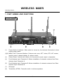
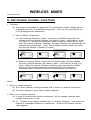
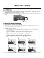
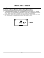
MA-909
Instruction Manual
ELECTRONICS CO., LTD.
Electronics Co., Ltd.
Head office: 814, Pei-Kang Road, Chiayi, 600, Taiwan.
Taipei office: 5, Lane 118, Sung-teh Road, Taipei, 110, Taiwan.
Web-http: //www.mipro.com.tw
E-mail: [email protected]
2CE194
B
WIRELESS MIXER
Operating Manual
The traditional design concept of the portable "all-in-one" wireless amplifier
consists of a unit with a CD player, cassette player, wireless receiver, and control
mixer mounted inside the active speaker cabinet. Although it is easy to use and
convenient for low power portable amplifier systems, this design is not suitable for use
in high power amplifier systems. It will not only be limited in its function and
performance, but it will also be inconvenient to operate. You can imagine how
inconvenient it is running to the speaker system far from you just to adjust the volume
or change a cassette or CD. To solve the inconvenience of operating such a high
power system and to incorporate its user-friendly functions into all operations, MIPRO
leads the market by designing the first integrated wireless interlinking amplifier system.
This new system separates the control mixer unit from the active speaker system.
The mixer unit contains a built-in high-fidelity wireless interlinking module which
transmits the mixed audio signals to the active speaker system. By doing so, users
can conveniently operate the system from the nearby "wireless mixer" instead of
running to the remote speaker system. In addition, the MA-909 wireless mixer can
transmit the mixed audio signals simultaneously to any active speaker system
equipped with an interlinking receiver module, without any connecting cable and with
total disregard to the quantity, specifications, or brand of speakers. Not only does the
MA-909 ensure compatibility with any existing PA system, but its agility in expanding a
system's output power or sound field provides maximum maneuverability and ease of
operation.
Main Features:
1.
2.
3.
4.
5.
6.
EIA Standard 2U metal case equipped with 2 built-in 16 frequency wireless microphone
system, high fidelity wireless interlinking transmitter, CD player, wired microphone
socket, LINE-IN socket for other audio sources, and LINE-IN/OUT sockets for recording.
A wired microphone, two wireless microphones, CD, cassette player, and other audio
sources can be mixed simultaneously at the input.
A separate wireless control mixer unit allows users to control active speaker systems
remotely to achieve the best performance.
Sixteen preset transmitter frequencies make selecting an interference-free frequency
simple and convenient.
The modular design of the interlinking wireless receiver allows it to be either built-in or
mounted on specific brands of active speaker systems.
Interlinking receiver modules installed on active speaker systems allows unlimited
expansion and change of setup position within the transmitter's range.
-1-
WIRELESS MIXER
Operating Manual
1. PART NAMES AND FUNCTIONS
Front Panel:
8
4
(1)
7
5
6
3
2
1
Power Switch & Indicator: When switch is turned on, the indicator illuminates to show
normal power status.
(2)(6) MRM-70 ACT Receiver Modules: Features auto scan, ACT button, RF & AF meters,
squelch control, channel display, & volume control.
(3)
Control Panel: Controls the volume of all sources & sends output to transmitter.
(4)
Front Antenna Input Connector A: Allows installation of extension antenna from Rear
Antenna Input Connector A.
(5)
Front Antenna Input Connector B: Allows installation of extension antenna from Rear
Antenna Input Connector B.
(7)
CD player
(8)
Transmitter (MT-90): Transmits audio to wireless speakers.
-2-
WIRELESS MIXER
Operating Manual
Back Panel:
9
10
11
12
13
(9)
Antenna: Receiver Antenna.
(10)
DC Input Jack: Connects unit to 12V DC from the AC/DC adaptor.
(11)
Power Supply Socket: AC cord socket
(12)
Transmitter Antenna: Transmits mixed audio to amplified speaker receiver modules.
(13)
Rackmount Brackets: Allow installation of the receiver into an EIA 19-inch standard
rack case.
-3-
WIRELESS MIXER
Operating Manual
A. Receiver Module Part Functions
A5
A6
A7
CHANNEL NOISE
A8
RF
SCAN
ACT
SENSITIVITY
AF
VOLUME
A4
A3
A2
A1
(A1) Power Switch / Volume Control: Allows you to turn the mixer on & off. The AF LED
light will flash when mixer is turned on. Increase the volume by turning in a
clockwise direction.
(A2) Audio Signal Level Indicator: Indicates the audio levels received from microphones.
(A3) Sensitivity Adjustment: Adjusts receiver sensitivity to ensure no noise output if receiver
is not receiving signals from transmitters.
(A4) ACT button: Matches the frequency of the microphone to the frequency of the
receiver.
(A5) SCAN button: Selects receiver channel or auto scans all frequencies.
(A6) Channel Indicator: Indicates the current receiver channel.
(A7) Noise Indicator: Indicates that the system is receiving interference.
(A8) RF Signal Level Indicator: Indicates the RF signal levels received from transmitters.
-4 -
WIRELESS MIXER
Operating Manual
B. SWITCHABLE CHANNEL FUNCTIONS
1. Functions:
(a) This system incorporates an advanced PLL-synthesized oscillator design which is
preprogrammed with 16 switchable frequencies. The user may freely select any
of the preprogrammed frequencies.
2. How To Select a Frequency:
(a) Auto Scanning Frequency Setup: Hold down the SCAN button (A5) and
release when the channel indicator (A6) starts to flash. It will flash for a total
of 6 times. To activate the AutoScan function, press the SCAN button once
while the channel indicator is flashing. An open frequency will automatically be
scanned and saved/locked. *Note: The AutoScan function works only while
the channel indicator is flashing (6 times).
a)
Pressandhold"SCAN"button
for1second.
CHANNEL NOISE
CHANNEL
SCAN
NOISE
c)
CHANNEL
AF
ACT
VOLUME
NOISE
d)
CHANNEL
AF
VOLUME
ACT
NOISE
RF
SCAN
-
+
SENSITIVITY
Whendoneitwillautosaved/locked.
RF
SCAN
-
+
SENSITIVITY
Press"SCAN" buttonagainandrelease
willautoscanforanopenfrequency.
RF
SCAN
ACT
LEDdisplayflashes.
b)
RF
-
+
SENSITIVITY
AF
ACT
VOLUME
+
SENSITIVITY
AF
VOLUME
(b) Manual Frequency Setup: Hold down the SCAN button (A5) and release
when the channel indicator (A6) starts to flash. It will flash for a total of 6
times. While the channel indicator is flashing, press and hold the SCAN
button until the desired frequency is displayed (they will increment in
ascending order). Release the button to automatically save/lock the
a)
Pressandhold"SCAN"button
for1second.
CHANNEL
NOISE
RF
CHANNEL
NOISE
c)
-
CHANNEL
AF
VOLUME
ACT
AF
VOLUME
ACT
Whendoneitwillautosaved/locked.
CHANNEL
NOISE
RF
SCAN
-
+
SENSITIVITY
d)
RF
NOISE
SCAN
-
+
SENSITIVITY
Press"SCAN"buttonandhold,
frequencywillchangeeverytwoflashes.
RF
SCAN
SCAN
ACT
LEDdisplayflashes.
b)
-
+
SENSITIVITY
AF
VOLUME
ACT
+
SENSITIVITY
AF
VOLUME
Notes:
1. When to change channels:
(a) The current channel is being interfered with or there is a channel malfunction.
(B) To avoid interference when using multiple channels.
2. When not to change channels:
(a) In order to avoid exiting channel interference", do not change channels while
multiple channels are in use.
(b) A "_" symbol on the display indicates that it is a blank frequency. This means the
channel is unavailable because of interference. Proceed until another numeric
value appears.
-5 -
WIRELESS MIXER
Operating Manual
C. ACT Button
1. Hold the transmitter to be programmed about 20 cm from the ACT button with the "ACT"
marking of the transmitter facing the ACT button.
2. Press the ACT button. The transmitter is programmed when the RF meter shows a full
signal.
ACT
D. Receiver Module Installation
1. Up to 2 receiver modules can be installed.
2. Each receiver module is equipped with "PILOTONE" and "NOISE LOCK" dual-squelch
circuitry that eliminates noise interference.
3. Installing/changing modules:
A. Remove the two mounting screws from the existing receiver module or blank
cover (Figure A).
B. Using a screwdriver, gently pry the module outward (Figure B).
C. Remove the existing module by sliding it out (Figure C).
D. Install new receiver module by sliding it in (Figure D).
E. Push the module all the way into the mixer slot (Figure E).
F. Secure with the two mounting screws (Figure F).
A
B
C
D
E
F
-6 -
WIRELESS MIXER
Operating Manual
E、 Control Panel Functions:
E7
E1
E2
E3
E4
E5
E6
E8
E9
(E1) Headphone Jack: Stereo headphone jack to monitor the mixer output.
(E2) Headphone Volume Control: Separately controls the headphone volume.
(E3) Master Volume Control: Controls the overall output volume of mixer.
(E4) LINE IN Volume Control: Separately controls the LINE IN (E7) volume.
(E5) MIC Volume Control: Separately controls the wired microphone (E9) volume.
(E6) MUSIC / SPEECH Switch: To change microphone input levels for music or speech
applications. Switching to SPEECH decreases the microphone input level.
(E7) LINE IN Input Jacks: Left and right unbalanced audio input jacks.
(E8) LINE OUT Jacks: Left and right audio output jacks.
(E9) MIC IN: Balanced/unbalanced wired microphone input jack.
F、Wireless Interlinking Transmitter - Parts and Functions
F2
F1
(F1)
Frequency switch button: Selects transmitter frequency.
(F2)
Transmitter frequency display.
-7 -
WIRELESS MIXER
Operating Manual
G、How to Setup Wireless Interlinking Transmitter:
1. To change transmitting channel, hold channel button on the front panel for 2 seconds.
After numeric LED starts blinking, press channel button again to change preset channel.
At this stage, channel will be changed when you press the channel button.
2. When numeric display has changed to one's desired channel, simply release the button
and channel setup is completed after numeric LED blinks six times.
CHANNEL
-7~1 -
WIRELESS MIXER
Operating Manual
2. CD Player installation:
A.
Remove screws holding the blank panel and remove the panel (see Fig. 3-1)
B.
Insert the CD player into the mixer (see Fig. 3-2)
C.
Reinstall screws to secure the player (see Fig. 3-3)
Fig. 3-1
Fig. 3-2
Fig. 3-3
-8 -
WIRELESS MIXER
Operating Manual
3. Operation Notes and Precautions:
1.
Microphones have priority over music inputs. When music is playing and a
microphone receives an audio signal, the music will be muted. As soon as there is
no longer an audio signal to the microphone, the music will fade in.
2.
Although the same frequency band may be used, it is important that the frequency of
the MT-90 transmitter and the MRM-70 receiver module are not the same. Otherwise,
the MA-909 will not operate properly.
3.
All audio sources to the MA-909 will be transmitted via the MT-90 transmitter to any
MR-90 receiver equipped active speaker. Please refer to attached Figures.
Active speaker system
High fidelity wireless interlinking
receiver module
Built-in high fidelity
wireless interlinking
transmitter
Professional wireless mixer unit.
4. Specifications :
Model Number
MA-909
Receiver Module
Accepts one or two MRM-70 UHF ACT receiver modules
Matching Transmitters
Handheld: ACT-707HE, Bodypack: ACT-707TE
Antennas
CD Player
Located on rear panel
Built-in anti-shock mechanism
Audio Input Jacks
Balanced/Unbalanced MIC & LINE-IN/LINE-OUT
T.H.D.
Frequency Response
Wireless Transmitter
< 0.5%
50Hz-15KHz±3dB
16 frequencies in the UHF 600MHz band
Power Supply
Dimensions (m/m)
Built-in 90~264V AC switching power supply
420 (L) x 44 (H) x 200 (D)
Weight (kg)
5.2
Exterior Color
Black
-9 -
HANDHELD WIRELESS MICROPHONE
Operating Manual
1. PART NAMES AND FUNCTIONS
1
2 3
4
5
6
7
8
(Fig.1)
1. Grill: Protects cartridge, prevents "POP" noise and prevents microphone from rolling with
polygonal shape.
2. Battery Status Indicator: Indicates power on / off and the battery status. When the power
switch is turned ON, the red LED indicator flashes briefly, indicating normal battery status.
If no flash occurs, the unit has no battery installed or the battery is either discharged or
installed incorrectly. If the indicator remains lit after power up, the battery is weak and
should be replaced.
3. Power On/Off Switch: Slide the switch to turn power "ON" or "OFF ".
4. Microphone Housing
5. Battery Compartment: Accommodates one 9-Volt battery.
6. Battery Compartment Cover
7. End Ring: An optional color ring may be installed here to identify multiple transmitters.
8. ACT Sensor: Receives ACT signals to automatically program the microphone frequency.
-10 -
HANDHELD WIRELESS MICROPHONE
Operating Manual
2. BATTERY INSTALLATION
(Fig.2)
1. Unscrew the battery cap (6) in a counter-clockwise direction.
2. Insert a 9-volt battery into the battery compartment (5), observing the correct polarity as
shown in Fig. 2. The moment the battery touches the terminals, the indicator (2) will flash
briefly, indicating correct polarity. However, if no flash occurs, either the polarity is
incorrect or the battery is dead. Please re-insert the battery, observing its correct polarity,
or exchange it for a fresh battery.
3. OPERATING INSTRUCTIONS
1. When the microphone is switched on:
The indicator will flash briefly indicating normal operation.
2. During use:
The AF LED indicator on the receiver will illuminate according to the audio signal strength
from the microphone.
3. When the microphone is not in use:
Make sure that you turn off the microphone to extend battery life. Remove the battery
from the battery compartment if the microphone is not to be used again for some time. If
a rechargeable battery was used, take it out and recharge it.
4. CAUTIONS
Under normal operation, when receiver and transmitter (mic) are paired together to a set
frequency, the microphone indicator (2) will remain off after ACT sets up the frequency.
However, if the indicator (2) is flashing, it means the receiver and transmitter (mic) are not in
the same frequency band.
Please check the stickers on the transmitter (mic) and receiver to verify that the
frequency bands match.
-11 -
BODYPACK TRANSMITTER
Operating Manual
1. PART NAMES AND FUNCTIONS
1
2
3
4
5
6
7
10
8
9
ACT
(Fig. 1)
1. MIC Input Jack: Connects to either a lavaliere or headset microphone. (See Section 3 for
connection details)
2. Power Switch: Switch to ON position for operation. Switch to OFF position when not in
use.
3. Battery Status Indicator (red): Indicates power on / off and battery status.
(a) When power switch is turned on: The LED indicator flashes briefly, indicating normal
battery status.
(b) When the LED indicator remains lit at either power on or during usage: The battery
level is low and replacement is necessary.
4. Antenna: 1/ 4-wave transmitting antenna.
5. Transmitter Housing
6. ACT Sensor: Receives the ACT signal to automatically program the transmitter frequency.
7. Gain Control: Adjusts the microphone input gain.
8. GT/MT Level Select Switch: Switch to GT position for instrument usage and "Line In".
Gain control is disabled in "GT" mode. Switch to "MT" for microphone usage. The gain
control will adjust the input sensitivity in "MT" mode.
-12 -
BODYPACK TRANSMITTER
Operating Manual
9. Battery Compartment and Cover: Accommodates one 9-Volt battery.
10.Detachable Belt Clip: Allows 360 degree rotation to suit transmitting angles. To detach
simply use a screwdriver at a 45 degree angle (see diagram).
2. OPERATING INSTRUCTIONS
1. To adjust GT/MT Switch (8), and Gain Control (7), simply push down both snap locks on
the sides of battery cover and flip it backwards to expose the adjustment panel.
2. To turn on the body pack, slide the power switch to the on position.
3. The LED indicator flashes briefly when power on indicating normal battery status. If no
flash occurs it either has no battery, the battery is drained, or installed incorrectly.
Change accordingly.
4. Plug the microphone connector into the input jack (1) and tighten the connector screw by
turning clockwise as shown in (Fig. 2).
CapsuleConnector
Headset
Lavalier
Lineuptheraisedlineon
the connectorwiththe
slotinthejackandinsert
(Fig.2)
-13 -
BODYPACK TRANSMITTER
Operating Manual
3. AF 4-PIN INPUT CONNECTION METHOD
(1) 2-Wire Electret Condenser Microphone Capsule
PIN
1
SHIELD
AUDIO
2
4
1
3
2
3
4
(2) 3-Wire Electret Condenser Microphone Capsule
SHIELD
PIN
1
2
AUDIO
4
1
3
BIAS
3
2
4
(3) Dynamic Microphone
2
1
SHIELD
PIN
1
3
2
AUDIO
4
1
3
2
3
4
(4) Electric Guitar
SHIELD
PIN
1
2
AUDIO
4
1
3
2
3
4
(5) Line-in (Impedance 8K ATT. 10dB)
SHIELD
AUDIO
PIN
1
2
3
4
-14 -
4
1
3
2
BODYPACK TRANSMITTER
Operating Manual
4. BATTERY INSTALLATION
1. Push down both snap-locks on the sides of battery cover to open (Fig. 3).
2. Insert a 9-volt battery into the battery compartment observing the correct polarity as
shown in (Fig. 4). Then close the battery compartment as shown in Fig. 4).
(Fig.3)
(Fig.4)
Note: When the microphone is not in use:
Make sure the power to the microphone is switched off. If the microphone will not be
used for some time, please remove the batteries from the battery compartment to avoid
battery leakage that could damage battery springs and circuitry.
5. CAUTIONS
Under normal operation, when receiver and transmitter (mic) are paired together to a set
frequency, the microphone indicator (2) will remain off after ACT sets up the frequency.
However, if the indicator (2) is flashing, it means the receiver and transmitter (mic) are not in
the same frequency band.
Please check the stickers on the transmitter (mic) and receiver to verify that the
frequency bands match.
-15 -