1
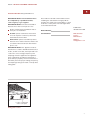
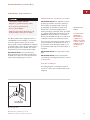
S EALED B URNER R ANGETOPS
I NSTALLATION I NSTRUCTIONS
As you follow these instructions, you will
notice WARNING and CAUTION symbols.
This blocked information is important for the
safe and efficient installation of Wolf equipment. There are two types of potential
hazards that may occur during installation.
signals a situation where minor injury or
product damage may occur if you do not
follow instructions.
states a hazard that may cause serious
injury or death if precautions are not
followed.
Another footnote we would like to identify is
IMPORTANT NOTE: This highlights information that is especially relevant to a problemfree installation.
WOLF ® is a registered trademark of Wolf Appliance Company, LLC
W O L F S E A L E D B U R N E R R A N G E TO P
I N S TA L L AT I O N R E Q U I R E M E N T S
IMPORTANT NOTE: This installation must
be completed by a qualified installer,
service agency or gas supplier.
IMPORTANT NOTE: Save these Installation
Instructions for the local inspector’s use.
Please read the entire Installation Instructions prior to installation.
Installer: please retain these instructions
for local inspector’s reference, then leave
them with the homeowner.
Homeowner: please read and keep these
instructions for future reference and be sure
to read the entire Use & Care Information
prior to use.
Record the model and serial numbers before
installing the sealed burner rangetop. Both
numbers are listed on the rating plate, located
under the control panel on the far right. Refer
to the illustration below.
Model Number
Serial Number
C O N TA C T
I N F O R M AT I O N
Wolf Customer
Service:
800-332-9513
Website:
wolfappliance.com
IMPORTANT NOTE: This appliance must be
installed in accordance with National Electrical
Codes, as well as all state, municipal and local
codes. The correct voltage, frequency and
amperage must be supplied to the appliance
from a dedicated, grounded circuit which is
protected by a properly sized circuit breaker or
time delay fuse. The proper voltage, frequency,
and amperage ratings are listed on the product
rating plate.
Location of rating plate
under control panel
Rating plate location
3
W O L F S E A L E D B U R N E R R A N G E TO P
B E F O R E YO U S TA RT
If the information in this book is
not followed exactly, a fire or
explosion may result, causing
property damage, personal injury
or death.
IMPORTANT NOTE:
Installation and service must be
performed by a qualified installer,
service agency or the gas supplier.
Warranty service must be performed
by a Wolf authorized service center.
Do not store or use gasoline or
other flammable vapors and liquids
in the vicinity of this or any other
appliance.
A ventilation hood is recommended
for use with the Wolf sealed burner
rangetop.
WHAT TO DO IF YOU SMELL GAS:
Do not try to light any appliance.
Do not touch any electrical switch.
Do not use any phone in your
building.
Immediately call your gas supplier
from a neighbor’s phone. Follow the
gas supplier’s instructions.
If you cannot reach your gas
supplier, call the fire department.
Proper installation is your responsibility.
Installations must be performed by a
qualified or licensed contractor, plumber or
gas fitter, qualified or licensed by the state,
province or region where this appliance is
being installed. You must also ensure that
electrical installation is adequate and
conforms with all local codes and
ordinances.
Wolf sealed burner rangetops are manufactured for use with natural gas or LP gas.
Please check the product rating plate for
type of gas needed.
Proper gas supply must be available;
refer to Gas Supply Requirements on
pages 10–12. Electrical ground is required;
see Electrical Requirements on page 13.
Check the location where the rangetop will
be installed. The location should be away
from strong draft areas, such as windows,
doors and strong heating vents or fans. Do
not obstruct the flow of air. The area in
which you are installing this appliance must
have an adequate supply of fresh air to
ensure proper combustion and ventilation.
Make sure you have everything necessary
for proper installation. It is the responsibility of the installer to comply with the installation clearances specified on the product
rating plate. The rating plate is located
under the control panel on the far right.
Refer to the illustration on page 3.
All openings in the wall where the rangetop
is to be installed must be sealed.
C O M M O N W E A LT H O F M A S S A C H U S E T T S
Installations and repairs must be performed
by a qualified or licensed contractor,
plumber or gasfitter qualified or licensed by
the state, province, or region where this
appliance is being installed.
Only use gas shut-off valves approved for
use within the state, province, or region
where this appliance is being installed.
A flexible gas connector, when used, must
not exceed 3' (.9 m).
4
I N S TA L L AT I O N I N S T R U C T I O N S
V E N T I L AT I O N O P T I O N S
I N S TA L L AT I O N S P E C I F I C A T I O N S
IMPORTANT NOTE: It is recommended that
you operate the Wolf sealed burner rangetop
with a Pro ventilation hood. Contact your Wolf
dealer for details.
Wolf sealed burner rangetops come in 30"
(762), 36" (914) and 48" (1219) widths. Illustrations on pages 7– 9 provide the overall dimensions and installation specifications for each
width of sealed burner rangetop.
Pro Wall Hood – 22" (559), 24" (610) or
27" (686) depths and 30" (762) to 66" (1676)
widths in classic stainless steel.
Pro Island Hood – 36" (914) to 66" (1676)
widths in classic stainless steel.
Pro Hood Liner – available in widths to
accommodate 30" (762) to 60" (1524) hood
shells.
All Pro ventilation hoods have welded seams,
sealed halogen lighting and removable, dishwasher-safe stainless steel filters.
Blower requirements may vary due to length
of duct work and number of angles. The basic
recommendation is 1 CFM per 100 Btu/hr.
Always consult your HVAC professional for
more concise blower requirements.
IMPORTANT NOTE: When installing a ventilation hood, refer to the specific requirements
of the hood for the minimum dimension to
countertop.
Dimensions in parentheses are in
millimeters unless otherwise specified.
Each rangetop is designed to fit between
cabinets set at the distance specified by the
unit. For example, a 36" (914) rangetop will fit
a 36" opening.
IMPORTANT NOTE: Cabinet opening dimensions shown in the Installation Specifications
illustrations must be used. These dimensions
provide for required clearances.
IMPORTANT NOTE: Locate the electrical
supply within dimensions shown in the
Installation Specifications illustrations.
ACCESSORIES
Optional accessories are available
through your
Wolf dealer. To
obtain local dealer
information, visit
the Locator section
of our website,
wolfappliance.com.
Refer to the Installation Specifications illustration for your model on pages 7– 9 for the exact
rough opening dimensions and location of the
gas and electrical supply.
Wolf sealed burner rangetops using natural
gas will operate up to an altitude of 8,000'
(2438 m) without any adjustment. Natural gas
and LP gas installations from 8,000' (2438 m)
to 11,000' (3353 m) need the high altitude
conversion kit. Contact your Wolf dealer for
details.
5
W O L F S E A L E D B U R N E R R A N G E TO P
MINIMUM C L E A R A N C E S
IMPORTANT NOTE: Caution must be used
in planning the proper installation of the Wolf
sealed burner rangetop to avoid fire or
damage to adjacent cabinetry or kitchen
equipment. Be sure to follow the minimum
clearances established in the finished rough
opening dimensions.
Refer to the Installation Specifications
illustration for your model on pages 7– 9 for
the exact rough opening dimensions.
W A L L I N S TA L L A T I O N S
Minimum clearances to combustible
surfaces:
Minimum 18" (457) clearance from bottom
of upper cabinet to countertop, within 6"
(152) minimum side clearance.
Minimum spacing between overhead side
cabinets must be greater than or equal to
the nominal width of the rangetop. The
maximum depth of overhead and side
cabinets is 13" (330), within 6" (152) side
clearance.
0" (0) clearance for adjacent combustible
materials below the countertop, both sides
and rear.
Bottom of ventilation hood must be 30"
(762) minimum to 36" (914) maximum from
countertop.
Minimum clearances for sealed burner
rangetops without a ventilation hood:
Model SRT304: 30" (762) minimum vertical
distance from countertop to combustible
materials above the rangetop.
All Other Sealed Burner Rangetops:
Surface Burners or Griddle (G) Models:
36" (914) minimum vertical distance from
countertop to combustible materials above
the rangetop.
Charbroiler (C) Models: 44" (1118) minimum
vertical distance from countertop to
combustible materials above the rangetop.
6
I S L A N D | P E N I N S U L A I N S T A L L AT I O N S
Minimum clearances to combustible
surfaces:
Island Installations: Minimum 12" (305)
clearance to rear wall that rises above the
countertop.
Peninsula Installations: Minimum 6" (152)
clearance to side walls and minimum 12"
(305) clearance to rear wall that rises above
the countertop.
Refer to the Installation Specifications
illustration for your model on pages 7– 9 for
the exact rough opening dimensions.
Failure to locate the rangetop without
the proper clearances will result in a fire
hazard.
RISER REQUIREMENTS
Installations against a combustible surface:
Model SRT304: No riser requirements.
36" (914) Sealed Burner Rangetops: A
minimum 5" (127) riser is required when
installing Model SRT366 against a
combustible surface. A minimum 10" (254)
riser is required for all charbroiler (C) or
griddle (G) models installed against a
combustible surface.
48" (1219) Sealed Burner Rangetops: A
minimum 10" (254) riser is required for all
charbroiler (C) or griddle (G) models
installed against a combustible surface.
I N S TA L L AT I O N I N S T R U C T I O N S
30" (762) S E A L E D B U R N E R R A N G E TO P
28 1/2" (724)
OVERALL DEPTH
9 1/4"
27 1/2"
(235)
(699)
WITH 20"
RISER
COOKING
SURFACE
12 1/2"
8 1/2" (216)
OVERALL
HEIGHT
(191)
Overall Width
Overall Height
(to cooking surface)
Overall Depth
29 7/8" (759)
OVERALL WIDTH
29 7/8" (759)
17 1/2"
(445)
(318) WITH 10"
WITH 5" RISER
RISER
7 1/2"
OVERALL DIMENSIONS
24 1/4"
Opening Width
(616)
8 1/2" (216)
28 1/2" (724)
30" (762)
Dimensions may vary to ± 1/8" (3).
I N S TA L L A T I O N S P E C I F I C A T I O N S
VENTILATION
HOOD
30" min (762)
COUNTERTOP
TO COMBUSTIBLE
MATERIALS
30" min (762)
TO 36" max (914)
TO BOTTOM OF
VENTILATION HOOD
6" min (152)
TO
COMBUSTIBLE
MATERIALS
13" max
(330)
18" min (457)
TO COUNTERTOP
COOKING
SURFACE
8 1/2"
(216)
30" (762)
OPENING WIDTH
3/4" (19)
PLATFORM
LOCATION OF GAS AND
ELECTRICAL SUPPLY CUT-OUT
WITHIN SHADED AREA
THROUGH BOTTOM OF
PLATFORM
16" (406)
36"
(914)
TOP VIEW
OF PLATFORM
7 1/2"
(191)
3/4" (19)
PLATFORM
24" (610)
BACK
WALL
4" (102)
E
G
16"
(406)
ISLAND INSTALLATIONS: 12" (305) MINIMUM
CLEARANCE FROM BACK OF RANGETOP TO
COMBUSTIBLE REAR WALL ABOVE COUNTERTOP–
0" (0) TO NON-COMBUSTIBLE MATERIALS
Dimensions in parentheses are in
millimeters unless otherwise specified.
7
W O L F S E A L E D B U R N E R R A N G E TO P
36" (914) S E A L E D B U R N E R R A N G E TO P
28 1/2" (724)
OVERALL DEPTH
OVERALL DIMENSIONS
Overall Width
Overall Height
(to cooking surface)
Overall Depth
Opening Width
35 7/8"
(911)
27 1/2"
(235)
(699)
WITH 20"
RISER
COOKING
SURFACE
8 1/2" (216)
8 1/2" (216)
OVERALL
HEIGHT
28 1/2" (724)
36" (914)
9 1/4"
12 1/2"
17 1/2"
(445)
(318) WITH 10"
WITH 5" RISER
RISER
7 1/2"
(191)
35 7/8" (911)
OVERALL WIDTH
24 1/4"
(616)
Dimensions may vary to ± 1/8" (3).
I N S TA L L A T I O N S P E C I F I C A T I O N S
IMPORTANT NOTE:
For 36" (914) sealed
burner rangetops,
a minimum 5" (127)
riser is required
when installing
Model SRT366
against a
combustible surface.
A minimum 10"
(254) riser is
required for all
charbroiler (C) or
griddle (G) models
installed against a
combustible surface.
VENTILATION HOOD
36" min (914)
COUNTERTOP
TO COMBUSTIBLE
MATERIALS
44" min (1118)
6" min (152) FOR CHARBROILER
TO
COMBUSTIBLE
MATERIALS
30" min (762) TO
36" max (914)
TO BOTTOM OF
VENTILATION HOOD
13" max
(330)
18" min (457)
TO COUNTERTOP
COOKING
SURFACE
8 1/2"
(216)
36" (914)
FINISHED ROUGH OPENING WIDTH
3/4" (19)
PLATFORM
LOCATION OF GAS AND
ELECTRICAL SUPPLY CUT-OUT
WITHIN SHADED AREA
THROUGH BOTTOM OF
PLATFORM
16" (406)
36"
(914)
TOP VIEW
OF PLATFORM
7 1/2"
(191)
3/4" (19)
PLATFORM
24" (610)
BACK
WALL
4" (102)
E
G
16"
(406)
ISLAND INSTALLATIONS: 12" (305) MINIMUM
CLEARANCE FROM BACK OF RANGETOP TO
COMBUSTIBLE REAR WALL ABOVE COUNTERTOP–
0" (0) TO NON-COMBUSTIBLE MATERIALS
8
I N S TA L L AT I O N I N S T R U C T I O N S
48" (1219) S E A L E D B U R N E R R A N G E TO P
28 1/2" (724)
OVERALL DEPTH
9 1/4"
27 1/2"
(235)
(699)
WITH 20"
RISER
COOKING
SURFACE
12 1/2"
8 1/2" (216)
(191)
Overall Height
(to cooking surface)
Overall Depth
47 7/8" (1216)
OVERALL WIDTH
47 7/8" (1216)
Overall Width
17 1/2"
(445)
(318) WITH 10"
WITH 5" RISER
RISER
7 1/2"
OVERALL
HEIGHT
OVERALL DIMENSIONS
24 1/4"
Opening Width
(616)
8 1/2" (216)
28 1/2" (724)
48" (1219)
Dimensions may vary to ± 1/8" (3).
I N S TA L L A T I O N S P E C I F I C A T I O N S
IMPORTANT NOTE:
For 48" (1219) sealed
burner rangetops,
a minimum 10" (254)
riser is required for
all charbroiler (C) or
griddle (G) models
installed against a
combustible surface.
VENTILATION HOOD
36" min (914)
COUNTERTOP
TO COMBUSTIBLE
MATERIALS
30" min (762) TO
36" max (914)
44" min (1118)
6" min (152) FOR CHARBROILER
TO
COMBUSTIBLE
MATERIALS
TO BOTTOM OF
VENTILATION HOOD
13" max
(330)
18" min (457)
TO COUNTERTOP
COOKING
SURFACE
8 1/2"
(216)
48" (1219)
FINISHED ROUGH OPENING WIDTH
3/4" (19) PLATFORM
16" (406)
36"
(914)
LOCATION OF GAS AND
ELECTRICAL SUPPLY CUT-OUT
WITHIN SHADED AREA
THROUGH BOTTOM OF
PLATFORM
TOP VIEW
OF PLATFORM
7 1/2"
(191)
3/4" (19)
PLATFORM
24" (610)
BACK
WALL
4" (102)
E
G
16"
(406)
ISLAND INSTALLATIONS: 12" (305) MINIMUM
CLEARANCE FROM BACK OF RANGETOP TO
COMBUSTIBLE REAR WALL ABOVE COUNTERTOP–
0" (0) TO NON-COMBUSTIBLE MATERIALS
Dimensions in parentheses are in
millimeters unless otherwise specified.
9
W O L F S E A L E D B U R N E R R A N G E TO P
I N S TA L L T H E R A N G E T O P
Prepare the finished rough opening for the
rangetop according to the Installation Specifications illustration for your model on pages
7–9. The platform must be 3/4" (19) thick and
include a cut-out at the right rear for gas
supply and electrical connections.
G A S S U P P LY R E Q U I R E M E N T S
EXPLOSION HAZARD —
Use a certified gas supply line and install
a gas shut-off valve.
Securely tighten all gas connections.
IMPORTANT NOTE: The platform must be
level to ensure that the cooking surface is
level.
The maximum gas supply pressure to the
regulator should never exceed 14" (34.9
mb) WC (water column); .5 psi (3.5 kPa).
Remove and discard all packing materials,
including cardboard and tape on the outside of
the rangetop. Remove the burner grates and
styrofoam off the top cooking surface. Be
sure to remove the burner caps packaged in
styrofoam below the burner grates.
Failure to do so can result in explosion,
fire or death.
If your installation requires a riser, it must be
attached to the rangetop before installation.
Refer to the installation instructions packaged
with the riser.
Position the rangetop on the platform. Gas
supply and electrical connections should be
made before the rangetop is placed in its final
position.
TYPES OF GAS
There are two types of gas, natural and liquid
propane (LP). Conversions are required in
order for appliances designed for one gas to be
operated with the other gas. Such conversions
must be performed by a Wolf authorized
service center. Make sure your Wolf sealed
burner rangetop is correctly adjusted for the
type of gas being used.
The product rating plate has information on
the type of gas that should be used. The rating
plate is located under the control panel on
the far right. Refer to the illustration on page 3.
If this information does not agree with the
type of gas available, contact your Wolf
dealer. To obtain local dealer information,
visit the Locator section of our website,
wolfappliance.com.
Wolf sealed burner rangetops using natural gas
will operate up to an altitude of 8,000' (2438 m)
without any adjustment. Natural gas and LP
gas installations from 8,000' (2438 m) to
11,000' (3353 m) need the high altitude conversion kit. Contact your Wolf dealer for details.
10
I N S TA L L AT I O N I N S T R U C T I O N S
G A S S U P P LY R E Q U I R E M E N T S
If rigid pipe is used as a gas supply line, a
combination of pipe fittings must be used to
obtain an in-line connection to the rangetop.
All strains must be removed from the supply
and gas lines so the rangetop will be level and
in line.
Before connecting the gas supply, make
sure all valves are in a closed position.
Do not connect the gas supply to an
appliance that shows any sign of physical
damage.
G A S S U P P LY C O N N E C T I O N
Provide a gas supply line of 3/4" rigid pipe to
the rangetop location. A smaller size pipe on
long runs may result in insufficient gas supply.
Pipe joint compounds, suitable for use with LP
gas should be used. For LP gas, piping or
tubing size can be 1/2" minimum. LP gas suppliers usually determine the size and materials
used on the system.
If local codes permit, a certified, 3' (.9 m) long,
or 3/4" ID flexible metal appliance connector
is recommended for connecting this rangetop
to the gas supply line. Do not kink or damage
the flexible connector when moving the
rangetop. The pipe fitting coming out the
bottom of the unit has 1/2" female threads. You
will need to determine the fittings required,
depending on the size of your gas supply line,
flexible metal connector and shut-off valve.
1/ 2"
IMPORTANT NOTE: The supply line must
be equipped with an approved external gas
shut-off valve located near the rangetop in an
accessible location. Do not block access to the
shut-off valve. Refer to the illustration below.
IMPORTANT NOTE: All connections to the gas
piping must be wrench-tightened. Do not make
connections too tight, this may crack the gas
pressure regulator and cause a gas leak. Do
not allow the pipes to turn when tightening
fittings as the tubing in the burner box may
bend and begin to leak.
I M P O R TA N T
N OT E
This installation
must conform with
local codes and
ordinances. In the
absence of local
codes, installations
must conform with
the American
National Standard,
National Fuel Gas
Code.
Assemble the flexible metal connector from
the gas supply to the gas pressure regulator,
located inside the rangetop. Determine the
fittings required depending on the size of your
gas supply line, flexible metal connector and
shut-off valve. Refer to the illustration below. If
a flexible metal connector is used, be sure the
tubing is not kinked. Use a pipe-joint compound
made for use with natural and LP gas.
Open the shut-off valve in the gas supply line.
Wait a few minutes for the gas to move
through the line.
SHUT-OFF VALVE
Open Position
Bottom of
Rangetop
Shut-Off Valve
Adapter
Nipple
To Appliance
Gas Supply
Line
Shut-off valve
Dimensions in parentheses are in
millimeters unless otherwise specified.
(use pipe-joint
compound on ends)
Adapter
Flexible Metal
Connector
Elbow
(use pipe-joint
compound on ends)
Gas supply connection
11
W O L F S E A L E D B U R N E R R A N G E TO P
G A S S U P P LY R E Q U I R E M E N T S
GAS MANIFOLD PRESSURE
For Natural Gas: Standard orifices
are set for 5" (12.5 mb) WC (water column).
A natural gas pressure regulator is
installed.
For Propane (LP) Gas: Standard orifices
are set for 10" (25 mb) WC (water column).
A propane gas pressure regulator is
installed.
Gas Supply Pressure: For checking the
regulator setting, the maximum line
pressure for natural and propane (LP) gas:
14" (34.9 mb) WC; .5 psi (3.5 kPa). Minimum
line pressure for natural gas: 7" (17.5 mb)
WC. Minimum line pressure for propane
(LP) gas: 11" (27.4 mb) WC.
Gas Supply Regulator: To control and
maintain a uniform gas pressure in the gas
manifold, the unit must be used with a gas
pressure regulator. The burner orifices, etc.
are sized for the gas pressure delivered by
the supplied regulator. Do not remove the
regulator.
The maximum gas supply pressure to
the regulator should never exceed 14"
(34.9 mb) WC; .5 psi (3.5 kPa).
12
GAS LEAK TESTING
Use a brush and liquid detergent to test all gas
connections for leaks. Bubbles around connections will indicate a leak. If a leak appears, shut
off the gas valve and adjust connections. Then
check connections again. Clean all the detergent solution from the rangetop.
Never test for a gas leak with a match or
other flame.
I N S TA L L AT I O N I N S T R U C T I O N S
ELECTRICAL R E Q U I R E M E N T S
R E C O M M E N D E D G RO U N D M E T H O D
ELECTRICAL SHOCK HAZARD –
Plug into a grounded 3-prong outlet.
Do not remove ground prong.
Do not use an adapter.
Failure to follow these instructions can
result in electric shock, fire or death.
The Wolf sealed burner rangetop requires a
110/120 V AC electrical supply to operate the
electronic ignition system. The 6' (1.8 m)
power supply cord provided with the rangetop
is equipped with a 3-prong, grounded plug for
protection against shock hazard. The service
should have its own 15 amp circuit breaker.
IMPORTANT NOTE: You must follow all
National Electrical Code and gas regulations.
In addition, be aware of local codes and ordinances when installing your services.
IMPORTANT NOTE: This appliance must be
properly grounded to avoid shock hazard.
The rangetop is equipped with a 3-prong
ground plug. To minimize possible shock
hazard, the cord must be plugged into a
mating 3-prong ground-type outlet, grounded
to conform with the National Electrical Code,
ANSI/NFPA 70 latest edition, or Canadian
Electrical Code (CSA) and all local codes and
ordinances. Refer to the illustration below.
You must have a properly grounded, 3-prong
outlet installed by a qualified electrician. A
ground fault circuit interrupter (GFCI) is not
recommended and may cause interruption of
operation.
I M P O R TA N T
N OT E
You must follow
all National
Electrical Code
regulations. In
addition, be aware
of local codes and
ordinances when
installing your
service.
IMPORTANT NOTE: Do not ground to a gas
pipe.
IMPORTANT NOTE: Reverse polarity will
cause nuisance clicking when power is turned
on to the unit.
WIRING DIAGRAM
The wiring diagram covering the electrical
circuit is located on the inside left wall of the
rangetop.
Grounding Plug
Grounding-Type
Electrical Outlet
Electrical ground
Dimensions in parentheses are in
millimeters unless otherwise specified.
13
W O L F S E A L E D B U R N E R R A N G E TO P
S U R FAC E B U R N E R S
R E M OV I N G T H E R A N G E T O P
INITIAL LIGHTING
The surface burners use electronic igniters in
place of standing pilots. When the rangetop
control knob is pushed in and turned to the
HIGH position, the system creates a spark to
light the burner. This sparking continues until
the electronic ignition senses a flame.
Be sure to place the burner heads on each
burner base and position the burner grates
over the burner bases and heads before
lighting.
To check operation of the surface burners,
push in and turn each control knob to the HIGH
position. The flame should light within four
seconds.
If the burners do not light properly, turn
control knob to the OFF position. Check that
the burner caps are in the proper position.
Check that the power supply cord is plugged in
and that the circuit breaker or house fuse has
not blown. Check that the shut-off valve is in
the ON position. Check operation again; if the
burners do not light properly at this point,
contact a Wolf authorized service center.
IMPORTANT NOTE: Initial lighting of the
surface burners may take slightly longer, as air
in the system must be purged before gas can
be supplied to the burner.
14
Be sure to disconnect the gas supply and
electrical connections before removing
the rangetop.
If removing the rangetop is necessary for
cleaning or service, shut off the gas supply.
Disconnect the gas supply and electrical
connections to the unit, then remove the
rangetop. Reinstall in the reverse order and be
sure to check the gas connection for leaks.
Refer the Wolf Sealed Burner Rangetops
Use & Care Information included with the
rangetop for cleaning recommendations.
I N S TA L L AT I O N I N S T R U C T I O N S
TROUBLES H O OT I N G
I F Y O U N E E D S E RV I C E
IMPORTANT NOTE: If the rangetop does not
operate properly, follow these troubleshooting
steps:
If service is necessary, maintain the quality
built into your Wolf sealed burner rangetop
by calling a Wolf authorized service center.
Verify that power is being supplied to the
rangetop.
To obtain the name and number of a
Wolf authorized service center, check
the Locator section of our website,
wolfappliance.com or call Wolf Customer
Service at 800-332-9513.
If nuisance clicking occurs when power is
supplied to the unit, check the electrical
outlet for reverse polarity.
Check the gas supply and electrical
connections to ensure that the installation
has been completed correctly.
Check that gas valves are turned to the ON
position.
When calling for service, you will need the
rangetop model and serial numbers. Both
numbers are listed on the product rating
plate, located under the control panel on
the far right. Refer to the illustration on
page 3.
C O N TA C T
I N F O R M AT I O N
Wolf Customer
Service:
800-332-9513
Website:
wolfappliance.com
Follow troubleshooting procedures as
described in the Wolf Sealed Burner
Rangetops Use & Care Information.
If the rangetop still does not work, contact a
Wolf authorized service center. Do not
attempt to repair the rangetop yourself.
Wolf is not responsible for service required
to correct a faulty installation.
The information and images are the copyright
property of Wolf Appliance Company, LLC, an
affiliate of Sub-Zero Freezer Company, Inc.
Neither this book nor any information or images
contained herein may be copied or used in whole
or in part without the express written permission
of Wolf Appliance Company, LLC, an affiliate of
Sub-Zero Freezer Company, Inc.
©Wolf Appliance Company, LLC all rights reserved.
15
W O L F A P P L I A N C E C O M PA N Y, L L C
808175
3 / 2006
P. O. B OX 4 4 8 4 8
MADISON, WI 53744
800-332-9513
W O L FA P P L I A N C E . C O M