1
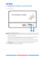
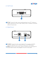
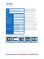
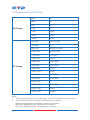
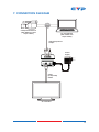
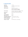
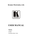
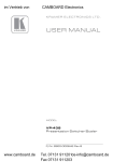
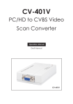
CV-401V
PC/HD to Video Scan Converter
Operation Manual
DISCLAIMERS
The information in this manual has been carefully checked and
is believed to be accurate. Cypress Technology assumes no
responsibility for any infringements of patents or other rights of third
parties which may result from its use.
Cypress Technology assumes no responsibility for any inaccuracies
that may be contained in this document. Cypress also makes no
commitment to update or to keep current the information contained
in this document.
Cypress Technology reserves the right to make improvements to this
document and/or product at any time and without notice.
COPYRIGHT NOTICE
No part of this document may be reproduced, transmitted,
transcribed, stored in a retrieval system, or any of its part translated
into any language or computer file, in any form or by any means—
electronic, mechanical, magnetic, optical, chemical, manual, or
otherwise—without express written permission and consent from
Cypress Technology.
© Copyright 2011 by Cypress Technology.
All Rights Reserved.
Version 1.1 August 2011
TRADEMARK ACKNOWLEDGMENTS
All products or service names mentioned in this document may be
trademarks of the companies with which they are associated.
SAFETY PRECAUTIONS
Please read all instructions before attempting to unpack, install or
operate this equipment and before connecting the power supply.
Please keep the following in mind as you unpack and install this
equipment:
•
Always follow basic safety precautions to reduce the risk of fire,
electrical shock and injury to persons.
•
To prevent fire or shock hazard, do not expose the unit to rain,
moisture or install this product near water.
•
Never spill liquid of any kind on or into this product.
•
Never push an object of any kind into this product through any
openings or empty slots in the unit, as you may damage parts
inside the unit.
•
Do not attach the power supply cabling to building surfaces.
•
Use only the supplied power supply unit (PSU). Do not use the PSU
if it is damaged.
•
Do not allow anything to rest on the power cabling or allow any
weight to be placed upon it or any person walk on it.
•
To protect the unit from overheating, do not block any vents or
openings in the unit housing that provide ventilation and allow for
sufficient space for air to circulate around the unit.
REVISION HISTORY
VERSION NO.
DATE DD/MM/YY SUMMARY OF CHANGE
VR0
07/04/11
Preliminary Release
VS1
11/10/12
Updated format/diagrams
CONTENTS
1. Introduction�������������������������������������������� 1
2. Applications������������������������������������������� 1
3. Package Contents�������������������������������� 1
4. System Requirements���������������������������� 1
5. Features�������������������������������������������������� 2
6. Operation Controls and Functions������� 3
6.1 Top Panel������������������������������������������3
6.2 Left Panel������������������������������������������4
6.3 Right Panel����������������������������������������4
6.3 OSD Menu�����������������������������������������5
6.4 Supported Input Timing�������������������7
7. Connection Diagram���������������������������� 8
8. Specifications���������������������������������������� 9
9. Acronyms��������������������������������������������� 10
1. INTRODUCTION
The PC/HD to Video Scan Converter is designed to down-scale PC/
Component source to analog CVBS (NTSC,PAL) signal. Ideal for
businesses with multiple CCTV cameras, this device takes your highresolution camera footage and scales it to lower resolutions.
Supporting PC resolutions up to WUXGA@60 Hz, this scaler can also
connect new video sources to older displays. The device has many
great features such as 3D noise reduction, frame rate conversion,
adaptive contrast enhancement and many more. It also has a simple
on-screen display (OSD) menu that allows the user to access the
display status including input/output information.
2. APPLICATIONS
• Security camera display
• Display PC signal to non-VGA CRT TV or monitor
• Display PC signal to non-VGA LCD TV or monitor
3. PACKAGE CONTENTS
• PC/HD to Video Scan Converter
• Power Adaptor
• Operation Manual
4. SYSTEM REQUIREMENTS
Input source equipment such as a PC/Component (RGBHV/YPbPr)
camera with D-Sub 15-pin or Component adaptor cable and output
display (TV or monitor) with CVBS input port and cable.
1
5. FEATURES
• Converts the video signal from PC/Component source to NTSC or
PAL signal
• Accepts a wide range of input resolutions of 480i to 1080p@60 Hz
(Component) and VGA to WUXGA@60 Hz (PC)
• 3D noise reduction in both temporal and spatial domain
• Frame rate conversion
• Adaptive contrast enhancement
• OSD Display
• Overscan and underscan adjustment
• Phase and Aspect adjustment
• No software installation required
• Compact and elegant design
Note: The converter do NOT support the following conversion:
-- Interlace source signal conversion between 50/60 Hz
-- 480i and 1080i@60 to PAL frame rate conversion
-- 576i and 1080i@50 to NTSC frame rate conversion
2
6. OPERATION CONTROLS AND FUNCTIONS
6.1 Top Panel
1
2
1 NTSC/PAL MENU (Hold): Press this button to bring up the On-Screen
Display (OSD) which will display the input timing and the output TV
format information.
When the OSD is displayed, press the button again to switch the
output TV system from NTSC to PAL or from PAL to NTSC.
Press and hold this button for 3 seconds the OSD will bring up the
selection menu. Press it sequentially to select the required setting.
2 POWER LED: This LED will illuminate in RED when the unit is
connected to the power supply.
3
6.2 Left Panel
1
1 PC IN: Connect to the source equipment such as a PC, laptop or
digital camera with D-sub 15pin cable (VGA) or adaptor converter
cable (Component).
6.3 Right Panel
1
2
1 CV OUT: Connect to the output display TV or monitor with RCA
cable for display of the converted composite (CVBS) signal.
2 DV5V: Plug the 5 V DC power supply included in the package into
the unit and connect the adaptor to an AC wall outlet.
4
6.3 OSD Menu
IN
640×480 (Input Timing)
OUT
NTSC (Output TV System)
Press the Menu button once
to bring up the OSD and
display the input (IN) and
Output (OUT) information.
NTSC
Press and hold the MENU
PAL
button for 3 seconds to
bring up the OSD then
Underscan 1
press it repeatedly to move
Underscan 2
the OSD cursor to the
Overscan
Phase Adj.
desired selection. Once
0~31
the selection is made, if the
Full Screen
MENU button is not pressed
Lette (RB)ox
Aspect Adj.
Pan & Scan
for a few seconds, the OSD
will disappear and the
display will output following
Auto TV 4:3
the selected parameters.
Auto TV 16:9
Below is the example of the scan selection result.
4:3
Source
5
TV
Underscan1
Underscan2
Overscan
Phase Adjustment: Range is from 0~31 and can be used to
compensate for blurry image quality and/or character jiggle.
Aspect Adjustment: There are total of 5 different aspect ratio
adjustments: Full Screen, Lette (RB)ox, Pan & Scan and Auto TV 4:3 &
Auto TV 16:9.
Full Screen: To allow the image to fill the screen of the TV.
Lette (RB) ox: To fit a 16:9 formatted video signal on a 4:3 display.
Horizontal Black bars will be displayed above and below the image
Pan & Scan: To fit a 4:3 formatted video signal on a 16:9 display.
Vertical black bars will be displayed at both sides of the the image.
Auto TV 4:3: The device will detect the input source aspect ratio of 4:3
or 16:9 and make the automatically make the adjustment to 4:3.
Auto TV 16:9: The device will detect the input source aspect ratio of
16:9 or 4:3 and automatically make the adjustment to 16:9.
Blow is the sample chart of the selection result:
Source TV
Aspect
Adjust
Full
Screen
Lette (RB)
ox
16:9
×
16:9
×
Auto TV
16:9
×
×
×
4:3
16:9
Auto TV
4:3
×
4:3
4:3
Pan&Scan
×
×
×
6
6.4 Supported Input Timing
HD Timing
PC Timing
480i
60
480p
60
576i
50
576p
50
720p
50/60
1080i
50/60
1080p
50/60
640×480
60/72/75/85
720×400
70
800×600
56/60/72/75/85
1024×768
60/70/75/85
1152×864
70/75/85
1280×720
59/60
1280×768
60/60 (RB)
1280×800
60/60 (RB)
1280×960
59/60
1280×1024
59/60
1366×768
60/60 (RB)
1440×900
60/60 (RB)
1600×1200
60
1680×1050
60/60 (RB)
1920×1080
59/60
1920×1200
60 (RB)
Note:
1. If the input resolution is not supported, the OSD will show 'IN Not Support'.
2. The converter do NOT support the following conversion:
-- Interlace source signal conversion between 50/60 Hz
-- 480i and 1080i@60 to PAL frame rate conversion
-- 576i and 1080i@50 to NTSC frame rate conversion
7
7. CONNECTION DIAGRAM
OR
Component Camera
(with YPbPr to D-Sub
15-pin Cable)
PC or Notebook
(with VGA D-Sub
15-pin Cable)
VGA/Component
Output
Power
Supply
CVBS
(Composite)
Cable
TV or Monitor
8
8. SPECIFICATIONS
Input Port
1×VGA
Output Port
1×CVBS (Composite Video)
Output Video
NTSC/PAL
ESD Protection
Human body model:
±8 kV (air-gap discharge)
±6 kV (contact discharge)
Power Supply
5 V DC/1 A linear power adaptor (US/EU
standards, CE/FCC/UL certified)
Dimensions
64 mm (W)×104 mm (D)×26 mm (H)
Weight
120 g
Chassis Material
Plastic
Silkscreen Color
White
Operating Temperature
0 °C~40 °C/32 °F~104 °F
Storage Temperature
−20 °C~60 °C/−4 °F~140 °F
Power Consumption
3W
Relative Humidity
20~90 % RH (non-condensing)
9. ACRONYMS
ACRONYM
COMPLETE TERM
CRT
Cathode Ray Tube
LCD
Liquid Crystal Display
NTSC
National Television System Committee
PAL
Phase Alternating Line
VGA
Video Graphics Array
CYPRESS TECHNOLOGY CO., LTD
Home page: http://www.cypress.com.tw