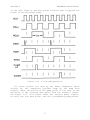
1
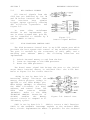
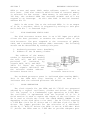
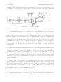
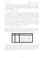
JADE COMPUTER PRODUCTS
PRESENTS
Double D
THE DOUBLE DENSITY DISK CONTROLLER
HARDWARE MANUAL
IOD-1200M
REVISION C
Copyright (C) 1980
Jade Computer Products
4901 Rosecrans Ave
Hawthorne, California
90250
All Rights Reserved
1
JADE COMPUTER PRODUCTS
4901 W. ROSECRANS BLVD
HAWTHORNE. CALIF 90250
SUBJECT:
PRODUCT:
REVISION:
DATE:
ENGINEERING CHANGE NOTICE # 1.
DOUBLE D DISK CONTROLLER.
BAND C REVISION BOARDS.
AUGUST 4. 1980.
IT HAS BEEN REPORTED THAT INSERTION OF THE DOUBLE D DISK
CONTROLLER INTO OF SOME S100 SYSTEMS PREVENTS NORMAL OPERATION.
USUALLY ON THESE SYSTEMS THE COMMON CHARACTERISTIC IS THAT THEY
JUST WILL NOT OPERATE. PLEASE NOTE S100 BUS PINS #20, #53, AND
#70 ARE CONNECTED TO GROUND, AS PER S100 STANDARDS, IEEE TASK
696.1/D2. THESE PIN CONNECTIONS DO CAUSE INTERFERANCE WITH IMSAI
FRONT PANEL SYSTEMS OR CPU BOARDS DESIGNED TO OPERATE WITH FRONT
PANELS. IT IS PERMISSABLE TO CUT THE FOIL LINKS CONNECTING PINS
#20, 53, AND 70 TO THEIR RESPECTIVE PLATE-THRU-HOLES. PLEASE
VERIFY IN YOUR SYSTEM DOCUMENTATION THAT THESE PINS ARE CAUSING
INTERFERENCE BEFORE CUTTING.
---------------------------------------------------------------SUBJECT:
PRODUCT:
REVISION:
DATE:
ENGINEERING CHANGE NOTICE # 2.
DOUBLE D DISK CONTROLLER.
BAND C REVISION BOARDS.
AUGUST 4, 1980.
A REVIEW OF THE DOUBLE D 8" PHASE LOCKED LOOP HAS BEEN
COMPLETED. THIS HAS RESULTED IN A RESELECTION OF SOME COMPONENT
VALUES. ENHANCED OPERATION, PARTICULARLY IN DOUBLE DENSITY, WILL
BE REALIZED WITH THE FOLLOWING MODIFICATION. THIS MODIFICATION
WILL DOUBLE THE LOOP CAPTURE RANGE AND ALSO ELIMINATE A CAUSE OF
LOOP INSTABILITY.
WITH THE EXCEPTION OF Rl, JUST CHANGE THOSE RESISTORS LISTED
FOR THE NEW VALUES AS SHOWN IN THE LIST. Rl DOES HAVE A CHANGED
VALUE BUT ALSO MUST BE INSTALLED SO THAT IT WILL CONNECT TO +5
VOLTS REGULATED INSTEAD OF THE PREVIOUS CONNECTION TO VX. WITH
CAREFUL LEAD BENDING AND RESISTOR PLACEMENT, ONE LEAD CAN SOLDER
TO THE +5V FOIL RUNNING FROM PIN #16 OF IC lA TO PIN #16 OF IC
lB. IT WOULD HELP TO SCRAPE SOME OF THE SOLDER MASK AWAY BEFORE
SOLDERING Rl TO THIS FOIL. VX WILL NOW MEASURE ABOUT +5.0 VOLTS.
INSTALLATION OF THE MODIFICATION WILL REQUIRE RETUNING THE PLL.
Rl
6.8K 1/4W (TO +5V)
R42 470K 1/4W
R3
12K 1/4W
R43 2.7K 1/4W
R4
10K 1/4W
R49 JUMPER
R38 20K 1/4W
---------------------------------------------------------------2
---------------------------------------------------------------SUBJECT:
PRODUCT:
REVISION:
DATE:
ENGINEERING CHANGE NOTICE # 3.
DOUBLE D DISK CONTROLLER.
BAND C REVISION BOARDS.
AUGUST 4, 1980.
THE DOUBLE D DISK CONTROLLER USES S-100 SIGNAL SWO*. CPUS
SUCH AS SBC-I00 AND SBC-200 DO NOT GENERATE THESE SIGNALS AND
THEREFORE
PRESENT
AN
INTERFACE
PROBLEM.
THE
FOLLOWING
MODIFICATION HAS SOLVED THE PROBLEM WITH THE ABOVE MENTIONED
BOARDS.
1.
ON THE SOLDER SIDE OF THE BOARD: CUT THE FOIL LINK FROM S-100
PIN # 97 TO THE PLATE-THRU-HOLE.
2. ON THE SOLDER SIDE OF THE BOARD: USING A SMALL GAUGE WIRE
JUMPER IC 1H PIN #2 TO IC 3J PIN #1.
---------------------------------------------------------------SUBJECT:
PRODUCT:
REVISION:
DATE:
ENGINEERING CHANGE NOTICE # 4.
DOUBLE D DISK CONTROLLER.
BAND C REVISION BOARDS.
AUGUST 4, 1980.
THE DOUBLE D DISK CONTROLLER EXHIBITS ERRATIC OPERATION WHEN
RUN WITH. THE BIG-Z Z80 CPU BOARD. THE PROBLEM EXISTS ON THE
BIG-Z BOARD. THE FOLLOWING MODIFICATION FIXES THIS PROBLEM.
NOTE: THE BIG-Z DOES NOT SEND OUT WRITE DATA TO THE S-100 BUS
UNTIL IT ACTUALLY SENDS THE WRITE STROBE. THIS MODIFICATION
ALLOWS THE WRITE DATA TO SETTLE ON THE S-100 BUS BEFORE THE
WRITE STROBE IS ISSUED.
1.
2.
ON THE SOLDER SIDE BIG-Z: CUT THE FOIL FROM IC 22 PIN # 13.
ON THE SOLDER SIDE BIG-Z: JUMP IC22 PIN # 13 TO PIN # 3.
----------------------------------------------------------------
3
---------------------------------------------------------------SUBJECT: ENGINEERING CHANGE NOTICE # 5B.
PRODUCT: DOUBLE.D DISK CONTROLLER.
REVISION: BAND C REVISION BOARDS.
DATE:
AUGUST 5. 1980.
IMPORTANT NOTICE! BOARD MODIFICATION NEEDED ON REVISION C.
THIS ECN PERTAINS TO THE USE OF THE DOUBLE D DISK CONTROLLER
WITH JADE RELEASE # 2 OF CP/M 2.2. CONNECTOR J3 PIN #48 WAS
DESIGNATED ILLEGAL PACK*. IT HAS BEEN REDEFINED AND IT IS NOW
DESIGNATED TWO SIDED*.
MANY SHUGART SA800/801. SIEMENS FD100-8. AND OTHER MODELS OF
DISK DRIVES HAVE OPTIONAL DATA SEPERATORS INSTALLED. DISK DRIVES
USING THESE OPTIONS USE PIN #48 OF THE 50 LINE RIBBON FOR THE
SEPERATED DATA* SIGNAL. AS RELEASE #2 (SPECIFICALLY DCM2)
MONITORS THIS SIGNAL LINE FOR TWO SIDED* ERRATIC DISK OPERATION
WOULD BE EXPECTED. PLEASE CUT THE FOIL LINK BETWEEN THE TWO
PLATE-THRU-HOLES AT J3 PIN #48 (REVISION C). FOR USE WITH THE
SA850/851 DISK DRIVE A JUMPER SHOULD BE INSTALLED .ON THE J3
PATCHING AREA FROM THE LOWER PIN # 48 PLATE-THRU-HOLE TO THE
UPPER PIN #10 PLATE-THRU-HOLE. THIS COMPLETES THE PATH FOR THE
TWO SIDED* SIGNAL FROM THE SA850/851.
.
---------------------------------------------------------------SUBJECT:
PRODUCT:
REVISION:
DATE:
ENGINEERING CHANGE NOTICE # 6.
DOUBLE D DISK CONTROLLER.
BAND C REVISION BOARDS.
AUGUST 5, 1980.
NOTE: CONCERNING THE DOUBLE D DISK CONTROLLER WHEN USED WITH
64K OF SYSTEM MEMORY OR ANY OTHER MEMORY ARRANGEMENT WHERE THE
DOUBLE .D MEMORY WINDOW OVERLAPS ASSIGNED MEMORY SPACE.
WHEN USED IN THIS CONFIGURATION THE PHANTOM BLOCK MUST BE
JUMPERED TO COMPLETE THE PHAN* SIGNAL PATH TO THE S100 BUS. THE
PHANTOM BLOCK IS LOCATED BELOW IC 4D. IT APPEARS AS TWO PLATETHRU-HOLES ENCLOSED BY A SILKSCREEN BORDER LABELED PHAN*. ADD A
JUMPER CONNECTING THESE TWO HOLES TOGETHER. ANY MEMORY BOARD
THAT THE DOUBLE D IS TO OVERLAP MUST BE CONFIGURED SO AS TO BE
DISABLED WHEN RESPONDING TO THE PHANTOM SIGNAL (PHAN*).
----------------------------------------------------------------
4
---------------------------------------------------------------SUBJECT:
PRODUCT:
REVISION:
DATE:
ENGINEERING CHANGE NOTICE # 7.
DOUBLE D DISK CONTROLLER.
BAND C REVISION BOARDS.
OCTOBER 6, 1980.
NOTE: USE NATIONAL SEMICONDUCTOR 74LS123 ONE-SHOTS ON THE
DOUBLE-D CONTROLLER BOARD. THE RESISTOR / CAPACITOR COMBINATIONS
HAVE BEEN SELECTED TO PROVIDE PROPER PULSE PERIODS WHEN USED
WITH THIS ONE-SHOT. DOUBLE D DISK CONTROLLER BOARDS (A&T AND
KIT) ARE NOW SUPPLIED WITH NATIONAL SEMICONDUCTOR 74LS123S.
CUSTOMERS WHO BUILD DOUBLE D BARE BOARDS TAKE NOTE.
---------------------------------------------------------------SUBJECT:
PRODUCT:
REVISION:
DATE:
ENGINEERING CHANGE NOTICE # 8.
DOUBLE D DISK CONTROLLER.
C REVISION BOARDS.
OCTOBER 6, 1980.
THE FOLLOWING LIST CONTAINS CORRECTIONS TO THE DOUBLE D
REVISION C SCHEMATIC OF 3/7/80. PLEASE MAKE THESE CORRECTIONS TO
YOUR DIAGRAMS.
1.
THE OUTPUT OF IC 1M (7406) PIN 6 TO THE PLATETHRU HOLE IN THE INTERRUPT BLOCK SHOULE BE
LABELED DINT*. (PAGE 1)
2.
A SECTION OF IC 3L (PINS 5 AND 15) HAS BEEN
DRAWN AND LABELED AS A 74LS244. THIS IS SHOWN ON
PAGE 1 CONNECTED TO THE 1791. THIS PART IS A
74LS240.
3.
AN INVERTING BUFFER, PART OF IC 3L (74LS240)
PINS AND 9, IS NOT SHOWN IN THE DIAGRAM. PIN 11
IS THE INPUT AND I CONNECTED TO DDEN. PIN 9 IS
THE OUTPUT AND IS THE SOURCE FOR DDEN*.
4.
FOUR PIN ASSIGNMENTS OF IC 3H (8131) ARE IN
ERROR. CHANGE PIN 13 TO PIN 11, PIN 12 TO PIN
10, PIN 11 TO PIN 13, AND PIN 10 TO PIN 12.
(PAGE 1)
5.
THE INPUT TO IC 4A ON PIN 13 IS LABELED AS
BPWR*. THIS LABEL SHOULD READ AS BPWR. (PAGE 2)
----------------------------------------------------------------
5
---------------------------------------------------------------SUBJECT:
PRODUCT:
REVISION:
DATE:
ENGINEERING CHANGE NOTICE # 9.
DOUBLE D DISK CONTROLLER.
BAND C REVISION BOARDS.
OCTOBER 6. 1980.
THE FOLLOWING JUMPER CONFIGURATION CAN BE USED WITH THE
SHUGART SA800/801 MODEL DISK DRIVE.
EACH DRIVE:
A,
DRIVE
DRIVE
DRIVE
DRIVE
DSI
DS2
DS3
DS4
A:
B:
C:
D:
LAST DRIVE:
Tl,
B,
C,
Y,
T2,
T3,
T4,
T5,
T6
HL,
800
THE L JUMPER IS SET DEPENDING ON THE -5V SUPPLY.
CONSULT YOU SA800 MANUAL. USE NO OTHER JUMP PLUGS
IN THIS CONFIGURATION.
SIEMENS DISK DRIVE MODELS FD120-8B AND THE NEWER FD100-8D CAN
BE USED THE JADE DOUBLE D. EACH DRIVE MUST HAVE THE RADIAL
SELECT OPTION PLUG SET TO THE PROPER DRIVE NUMBER" 0 SELECTS
DRIVE A, 1 SELECTS DRIVE B, 2 SELECTS DRIVE C, AND 3 SELECTS
DRIVE D. ONLY THE LAST DRIVE ON THE RIBBON SHOULD CONTAIN THE
RESISTOR PACK. BE SURE TO REVIEW ECN #5. NO OTHER CHANGES ARE
NEEDED.
THE FOLLOWING PAGE DESCRIBES A TESTED JUMPER CONFIGURATION
FOR THE SHUGART SA850/851 WHEN USED WITH JADE RELEASE # 2 OF
CP/M 2.2.
6
SHUGART SAS50/S51
------- --------START WITH THE DISK DRIVE(S) SET TO FACTORY CONFIGURATION AS
DESCRIBED IN THE SER1VE AND MAINTENANCE MANUAL. THEN PERFORM THE
FOLLOWING ALTERATIONS TO THE DRIVE(S).
1.
REMOVE THE ‘IW’ PLUG. THIS ALLOWS FOR LOWER WRITE CURRENT ON
THE INSIDE TRACKS.
2.
REMOVE THE ‘RS’ PLUG AND INSTALL THIS PLUG AT ‘RM’. THIS
ALLOWS DRIVE READY TRUE WHEN DIRECTION (SIDE SELECT) IS
SELECTING THE WRONG SIDE OF A SINGLE SIDED DISKETTE.
3.
BREAK CONNECTION ‘X’ ON THE SHORTING PLUG AND INSTALL A PLUG
AT ‘C’. THIS ALLOWS THE DRIVE TO BE SELECTED WITHOUT ENABLING
THE STEPPER OR LOADING THE R/W HEAD.
4.
BREAK CONNECTION ‘l’ ON THE SHORTING PLUG AND INSTALL A PLUG
AT ‘Y’. ACTIVITY LIGHT ON FROM R/W HEAD LOADED.
5.
REMOVE THE ‘S2’ PLUG AND INSTALL AT ‘S1’. THIS ALLOWS SIDE
SELECT FROM THE ‘STEP DIRECTION’ SIGNAL.
6.
REMOVE THE ‘851’ PLUG AND INSTALL AT ‘850’. THIS IS FOR SOFT
SECTORED DISKETTES.
7.
INSTALL A PLUG AT ‘2S’. THIS ALLOWS THE DRIVE TO ISSUE THE
‘TWO SIDED’ SIGNAL WHEN TWO SIDED DISKETTES ARE INSERTED.
8.
REMOVE THE ‘DL’ PLUG.
9.
SET -5/-15 ACCORDING TO THE NEGITIVE SUPPLY VOLTAGE YOU ARE
USING.
10. DRIVE
DRIVE
DRIVE
DRIVE
A:
B:
C:
D:
INSTALL
INSTALL
INSTALL
INSTALL
PLUG
PLUG
PLUG
PLUG
AT
AT
AT
AT
‘DS1’.
‘DS2’.
‘DS3’.
‘DS4’.
11. REMOVE THE TERMINATOR FROM ALL BUT THE LAST DRIVE ON THE
RIBBON CABLE.
12. INSTALL JADE DOUBLE D ECN # 5.
---------------------------------------------------------------ENGINEERING
7
---------------------------------------------------------------Subject:
Product:
Revision:
Date:
Engineering Change Notice # 10.
Double D Disk Controller - QUME DATATRAK 8 DRIVES
Band C boards. Release 2 software
May 8, 1981.
The following jumped options should be changed on the
DATATRACK 8 disk drive for use with the DOUBLE D
controller.
QUME
disk
1.
Remove programmable shunt from P.C. board socket. Bend pins
B, HL, and Z to prevent making contact. Replace shunt back
into socket.
2.
Insert shunt plugs at locations C, DS, Y, and 2S.
3.
Please read and perform Engineering Change Notice #5. It
applies to QUME DATATRACK 8 as well as the SHUGART SA850/851.
The following patch is required in DCM2. Location 111D hex was
OFB hex and should be changed to ODB hex. The new source code
for this line is:
TDL:
ANI
#(BC. DSE!BC. SD1)
ASM:
ANI
NOT ( BC$DSE OR BC$SDl )
Double D CP/M 2.2 distributed after Nov 30, 1981 includes this
modification (starting with S/N 2-187-1410).
ENJOY YOUR QUMES.
----------------------------------------------------------------
8
TABLE OF CONTENTS
DOUBLE D
TABLE OF CONTENTS
SECTION
DESCRIPTION
PAGE
1
1.1
1.2
1.3
INTRODUCTION
SCOPE
RELATED DOCUMENTATION
DESCRIPTION
1
1
1
1
2
2.1
2.2
2.3
2.4
2.5
2.6
2.7
2.8
2.9
2.10
2.11
2.12
2.13
2.14
2.15
2.16
2.17
2.18
2.19
2.20
2.21
HARDWARE DESCRIPTION
OVERVIEW
MEMORY ADDRESS DECODING
PORT ADDRESS DETECTION
BUS CONTROL SIGNALS
DISK PROCESSOR CONTROL PORT
DISK PROCESSOR STATUS PORT
CLOCK GENERATION
PROCESSOR
DISK CONTROLLER
DISK INTERFACE
INTERNAL I/O ADDRESSES
BOARD LEVEL STATUS PORT
BOARD LEVEL COMMAND PORT
ON-BOARD TIMER
STEP CONTROL
WAIT STATE GENERATOR
VECTOR INTERRUPT GENERATOR
EIA LEVEL INTERFACE
MEMORY CONTROL
WRITE PRECOMPENSATION
PHASE-LOCKED LOOP
3
3
3
4
5
5
6
6
7
7
8
8
9
10
11
11
12
12
12
13
14
14
3
3.1
3.2
3.3
BOARD ASSEMBLY
INTRODUCTION
ASSEMBLY
CONFIGURATION
19
19
19
25
APPENDICES
A
B
C
D
E
F
COMPONENT LAYOUT
PARTS LIST
INTERNAL SIGNAL DEFINITIONS
S-100 BUS CONNECTIONS
SCHEMATICS
FEEDBACK
9
SECTION 1
INTRODUCTION
SECTION 1
INTRODUCTION
1.1
SCOPE
This manual contains the complete hardware description of the
Jade Double Density Disk Controller. It provides the end user
with construction and configuration procedures, and a functional
description of the circuitry.
1.2
RELATED DOCUMENTATION
Double D Software Manual P/N IOD-1201M
FD 179X-01 Specifications
Z80A-CPU Technical Manual
1.3
Jade Computer Products
Western Digital Corp.
Zilog, Inc.
DESCRIPTION
The Double D is an intelligent S-100 based disk controller.
It is capable of handling up to four full size (8") or mini (5")
disk drives. Provisions have been made for double sided drives.
Single and double sided drives may be mixed. The controller is
capable of single density (FM) and double density (_FM)
operation. It can be used in software polled as well as
interrupt driven environments. Circuitry is implemented on a
four layer printed circuit board where one inside layer is used
as a ground plane. This provides for a minimal amount of ground
noise. This board was designed to meet the proposed 8-100 signal
disciplines as defined in IEEE Task 696.1/D2
The Double D contains an on-board Z80A microprocessor with 2K
of static memory.
The on-board processor runs simultaneously
with and transparent to the S-100 bus. All critic81 timing is
handled on board; data transfers are fully buffered by sector in
the on-board memory, two levels of interrupt are implemented on
the Z80A, and a wait state generator is used to synchronize the
on-board processor to the disk transfer rate. The host system
(8080, 8085, Z80, or ?) need only transfer comman0s and data
through a block of static memory, which can be accessed from the
bus. This architecture provides a high degree of timing
independence from the host system. Also, since the disk
controller program is contained on-board in ram, this board's
operational characteristics are redefinable at any time during
system operation.
1
SECTION 1
INTRODUCTION
The powerful FD 1791-01 Formatter/Controller is used to
encode and decode all data transfers to and from the disk
drives. It also provides for the generation and checking of
address marks, data marks, and the cyclic redundancy characters.
Write precompensation can be selected under software control at
three levels of intensity, providing flexible data recording.
Data separation is achieved by the use of a phase-locked loop to
insure maximum immunity to disk speed variation and to enhance
data recovery margins in both single and double density.
1.3
DEVICE SPECIFICATION
Power requirements:
System Port
Requirement:
System Memory
Requirement:
Recording Method:
External
Communication:
Disk Interface,
Connectors:
+7 TO +11 Volts
+14.5 to +21.5 volts
25 Ma. Typical
50 Ma. Maximum
-14.5 to -21.5 volts
8 Ma. Typical
30 Ma. Maximum
One I/O port,
switch selectable
40,41,42,43 Hex
1K Byte block
switch selectable
EOOO,E400,EPOO,ECOO,
FOOO,F400,FAOO,FCOO Hex
Single density in FM
Double density in MFM
One EIA compatible input signal
One EIA compatible output signal
50 Pin Card Edge Connector
AMP P/N 888083-1
3M P/N 3415-0001
8" Drives
5" Drives
System Interrupts:
0.90 Amp. Typical
1.50 Amp. Maximum
34 Pin Card Edge Connector
AMP P/N 583717-5
3M P/N 3463-0001
Optional Feature,
Vector Interrupt on
2
VIO* thru VI7*
SECTION 2
HARDWARE DESCRIPTION
SECTION 2
HARDWARE DESCRIPTION
2.1
OVERVIEW
The operational characteristics of the DOUBLE D are a
function of both hardware and on-board software. The hardware
provides the data paths, logic functions, and control signals
necessary to implement such operations as head loading, drive
selection, head positioning, and transferring data. It is the
software that determines how the disk controller commands are
interpreted and in what sequence controller events-take place.
As in all microprocessor designs, the software can do no more
than hardware implementation allows. The DOUBLE D is designed to
allow the on-board software as much control as possible. For the
user who will write control programs for this board, an
understanding of the hardware is recommended. This section
provides a description of the hardware.
2.2
MEMORY ADDRESS DECODING
The S-100 bus address lines are constantly monitored by the
Memory Address Detection circuit. See Figure 2-1. In the
Standard address mode, ICs 3H and 3B implement detection of the
selected 1K memory block. Switches M10, M11, and M12 are used
to locate the selected memory block on any 1K boundary from EOOO
to FCOO. Note: Signals SA10, SA11, and SA12 indicate the
corresponding address switch settings. See Table 2-1. For the
Extended Address Mode, IC 4B must be installed and the Address
Mode Block altered to the appropriate position. In this
configuration, address decoding is provided for any 1K block in
the upper 8K of the 24 bit address bus. In either mode, an
address match is indicated by BMA* (Bus - Memory Addressed)
being asserted (low).
SWITCH
M12
Closed
Closed
Closed
Closed
Opened
Opened
Opened
Opened
SWITCH
M11
Closed
Closed
Opened
Opened
Closed
Closed
Opened
Opened
SWITCH
M10
Closed
Opened
Closed
Opened
Closed
Opened
Closed
Opened
SA12
SA11
SA10
0
0
0
0
1
1
1
1
0
0
1
1
0
0
1
1
0
1
0
1
0
1
0
1
Table 2-1. Memory Address Selection
3
ADDRESS RANGE
IN THE SYSTEM
EOOO - E3FF
E400 - E7FF
E800 - EBFF
ECOO - EFFF
FOOO - F3FF
F400 - F7FF
FEOO - FBFF
FCOO - FFFF
SECTION 2
HARDWARE DESCRIPTION
Figure 2-1. Memory Address Detection
2.3
PORT ADDRESS DETECTION
S-100 address lines AO thru A7 are constantly monitored by
the Port Address Detection circuit. This circuit is composed of
IC 3F and part of 3E. See figure 2-2. Switches "PO" and "P1" are
used to vary the selected port address from 40 thru 43 hex. An
address match is indicated by BPA* (Bus - Port Addressed) being
asserted.
SWITCH
P1
Close
Close
Open
Open
Figure 2-2.
Port Address Detection
4
SWITCH
P0
Close
Open
Close
Open
ADDRESS
PORT
40
41
42
43
Table 2-2.
Port Address Selection
SECTION 2
2.4
HARDWARE DESCRIPTION
BUS CONTROL SIGNALS
All Control Signals from the
S100 bus are buffered by ICs 1H
and 3K before internal use. These
line
receivers
have
schmitt
trigger inputs typically offering
400
millivolts
hysteresis.
See
Figure 2-3.
In
some
older
mainframes
SLVCLR* is not implemented. For
use in those systems POC* (pin 99)
can be connected to SLVCLR* by 8
jumper (BRST* to POC*).
2.5
Figure 2-3.
Control Signal Buffers
DISK PROCESSOR CONTROL PORT
The Disk Processor Control Port is an S-100 output port which
provides the host system with control of the on-board processor.
The port is strobed by the occurrence of sOUT, pWR*, and a
matching port address (BPA*). The following functions are
implemented.
1.
2.
3.
Switch internal memory to and from the bus.
Issue an interrupt to the Z80A processor
Reset the Z80A processor.
The board reset signal BR* brings the port to the initial
state where internal memory is switched into. the S-100 bus.
Refer to Figure 2-4 for circuit details.
SLVRQ is set by date bit O.
Asserting SLVRQ* initiates the
memory switch process. SLVRQ* is
applied to the Z80A BUSRQ* pin.
When SLVRQ* (BUSRQ*) is asserted,
the Z80A tri-states its data,
address, and control lines. The
Z80A
then
asserts
SLVACK*
(BUSACK*). Refer to the Z80A
TECHNICAL MANUAL. Assertion of
SLVACK*
enables
the
Memory
Control circuit to respond to 8100 memory cycles.
Figure 2-4. Control Port
ZINT is set by data bit 1. ZINT(*) serves a dual function.
ZINT* is the maskable interrupt request to the on-board Z80A.
Note, circuit implementation makes it possible for the on-board
5
SECTION 2
HARDWARE DESCRIPTION
Z80A to test and reset ZINT* under software control.
More on
this later. ZINT also controls which 1K bank of internal memory
is selected for bus access. When memory is switched to the S100 bus, the on-board Z80A has asserted SLVACK* and will not
respond to an interrupt. At this time ZINT is used AS internal
address bit 10.
ZRST* is the reset line to the on-board Z80A. It is an output
of IC 1A, a one-shot, which is triggered by writing to this port
while data bit 7 is asserted high.
2.6
DISK PROCESSOR STATUS PORT
The Disk Processor Status Port is an S-100 input port which
allows the host processor to examine the current state of the
Disk Processor. The port responds to the occurrence of pDBIN,
sINP, and a matching port address (BPA* asserted). The following
states can be determined by reading this port.
1.
2.
On-board processor state (Run/Halt)
Address of the 1K memory window.
The address of the memory
window is determined by reading
the M10, M11, and M12 switch
positions
as
indicated
by
signals SA10, SA11, and SA12.
Table 2-1 shows the relation
between signals SA10-SA12 and
the selected window address.
Processor Status Port
Figure 2-5.
Processor Status Port
The on-board processor state is indicated when reading ZHLT*.
This is the Z80A halt flag. Reading a "0" on data bit 0
indicates that the on-board processor has halted.
2.7
CLOCK GENERATION
The clock signals for the Z80A and FD 1791-01 are generated
onboard by a crystal oscillator, divider and driver. See figure
2-6. The crystal is a fundamental type operating at 8.000 Mhz.
The oscillator is implemented with two sections of IC 3L. A
third section is used to square the output of the oscillator. IC
2M is used to divide the clock. The CLOCK SELECT JUMPER is set
depending on the disk drive to be used.' The FD 1791-01 requires
a 2.000 Mhz clock for 8" drives and a 1.000 Mhz clock for the 5"
drives. The jumper provides for the selection of a additional
divide by 2. With 8" drives the Z80A is run at 4.000 Mhz. With
5" ,drives the Z80A runs at 2.000 Mhz to provide adequate port
6
SECTION 2
HARDWARE DESCRIPTION
enable (RE* and WE*) timing for the FD 1791-01. A section of IC
1F and U-5 provide a MOS level clock driver for the Z80A as
recommended by Zilog.
Figure 2-6. Clock Circuit
2.8
PROCESSOR
The on-board processor function is implemented with the Z80A.
It was selected because of execution speed and compatibility
with TTL logic families. The processor uses the on-board 2K
static memory for program, stack, parameters, and for buffering
single/multiple sectors of data. Because the 5 upper address
bits are not decoded, this 2K block appears 32 times in the Z80A
64K address range. This allows internal programs to be assembled
on Bny 2K boundary. Note, the address selected for the memory
window has no effect on the on-board processor or the on-board
software.
The host system communicates with the on-board processor thru
the memory window. During a system boot, the control program
must be loaded thru the memory window before the on-board
processor can operate properly. It is entirely possible for the
initial control program to be a small bootstrap which then loads
a larger control program from disk. For reading and writing disk
sectors, the host system must block move sector data through the
memory window.
Both Z80A interrupts are implemented. The host system issues
the maskable interrupt by executing an OUTPUT instruction to the
Disk Processor Control Port. The FD 1791-01 issues an interrupt
upon command
completion.
The Z80A NMI* pin is used for
interrupts from the 1791-01. This interrupt is clamped by CR18
when DSE (Drive Select Enable) is low.
2.9
DISK CONTROLLER
The Western Digital 1791-01 is used for all data transfers to
and from disk. This device is addressed as four I/O ports from
7
SECTION 2
HARDWARE DESCRIPTION
the on-board processor. The user should refer to FD 1791-01
specifications for a detailed description of this part. Access
to the FD 1791-01 Status Port allows reading the disk interface
signals. These are WRITE PROTECT*, READY*, INDEX*, TRACK-ZERO*,
and SEEKCOMPLETE*.
2.10
DISK INTERFACE
Disk Interface is provided by two gold-plated card edges at
the top of the P.C. board. The 50 pin (J-3) card edge is
intended for the 8" disk drives. The mating connector is the
same type as is used to connect the other side of the ribbon
cable to the disk drive (with most drives). All even numbered
contacts (component side) are connected to internal circuitry
thru a double set of plate-thru-holes. By cutting the connecting
links and adding jumpers, the signal assignments for each
contact can be altered. The 34 pin card edge (J-2) is intended
for 5" disk drives. All unassigned contacts provide a platethru-hole for alteration. Additional signals can be assigned to
this connector by jumping from J-3 to J-2. On connectors J-2 and
J-3 all odd-numbered contacts are grounded.
2.11
INTERNAL I/O ADDRESSES
There are seven I/O ports available to the on-board processor.
These internal ports are not accessible from the host system.
They are used for control signals, status information, and data
paths. They are decoded using address bits AO thru A2.
ADDR
00
00
04
04
05
06
07
TYPE
Input
Output
Input
Output
I/O
I/O
I/O
Table 2-3.
DESCRIPTION
Board Level Status
Board Level Command
Disk Controller Status
Disk Controller Command
Disk Controller Track
Disk Controller Sector
Disk Controller Data
Internal I/O Ports
Address bits A3 thru A7 have no effect on I/O operations
except when accessing the Board Level Status Port. These upper
address bits individually trigger on-board events when asserted
high during an INPUT operation from this port. A list is
provided in Table 2-4. For a detailed description refer to the
appropriate section.
8
SECTION 2
HARDWARE DESCRIPTION
BIT
FUNCTION
SECTION
A3
A4
A5
A6
A7
Issue Step Pulse
Clear Timer
Reset Host Interrupt
Initiate Timer
Wait State Request
2.15
2.14
2.5
2.14
2.16
Table 2-4.
2.12
Address Bit Assignments
BOARD LEVEL STATUS PORT
The Board Level Status Port is a parallel input port to the
onboard Z80A. It provides the processor with access to board
signals that cannot be read from the FD 1791-01. These signals
are listed and described in Table 2-5. See Figure 2-7 for
circuit diagram.
DATA
BIT
0
1
2
3
4
5
6
7
SINGAL
NAME
UO
U1
TST*
ZINT
SERI
TOFF
ILP*
CHNG*
Table 2-5.
DESCRIPTION
User 0 switch setting
User 1 switch setting
Test mode
Interrupt req from host
EIA level input bit
Timer off
Illegal pack inserted
Disk has been changed
Board Level Status Bits
Figure 2-7.
Board Level Ports
9
SECTION 2
2.13
HARDWARE DESCRIPTION
BOARD LEVEL COMMAND PORT
The Board Level Command Port is a parallel output port of the
on-board processor.
It
is
used
to
select
various
parameters as listed in Table 2-6. See Figure 2-7 for circuit
details.
DATA
BIT
0
1
2
3
4
5
6
7
SIGNAL
NAME
DSA
DSB
DSE
SERO
DDEN
SID1
PCA
PCB
DESCRIPTION
Drive select bit A 2**0.
Drive select bit B 2**1
Drive select enable
EIA signal output control
Double density enable
Side and direction select
Precomp select A
Precomp select B
Table 2-6.
Command Port Bits
The signals DSA and DSB are used
to
determine
which
drive
is
selected. DSE must be asserted for
drive selection to take place. DSE
is also used to enable the on-board
processor to accept an interrupt
from the 1791-01. See Table 2-7 for
drive selection.
Double
Density
operation
is
enabled when DDEN is set high. A low
SERO
signal
corresponds
with
a
negative EIA output.
DSE
DSB
DSA
0
1
1
1
1
X
0
0
1
1
X
0
1
0
1
DRIVE
NONE
0
1
2
3
Table 2-7.
Drive Selection
SID1 serves a dual function. When using double-sided drives
and performing any type of read or write operation, this signal
selects which side of the diskette is used. A low SID1 selects
the same side as used on single-sided drives. When stepping
operations are being performed, SID1 functions as the direction
select, a low SID1 will cause stepping operations to move the
head toward track 0 (most drives) .
Precompensation is controlled by signals PCA and PCB. These
two signals allow precompensation to be enabled and at different
three levels of intensity. Table 2-8 lists this function.
10
SECTION 2
HARDWARE DESCRIPTION
PCB
PCA
0
0
1
1
Table 2-8.
2.14
PRECOMPENSATION
0
1
0
1
OFF
200 ns.
160 ns.
120 ns.
Write Precompensation
ON-BOARD TIMER
The
On-Board
Timer
provides
both
a
motor
control for 5" drives and
a means for deselecting
any drive if not used for
a given period of time.
The 1791-01 will unload
the head of a drive if not
used in 15 revolutions,
but in some drives the
stepper-motor will still
Figure 2-8.
consume power. The timer
On-board Timer
is under complete control
of the onboard processor. It can be set, reset, and examined by
appropriate I/O operations. See figure 2-8.
2.15
STEP CONTROL
The STEP CONTROL circuit provides more flexible control of
the step function than the 1791-01. Step pulses are issued under
control of the on-board processor. The
interval
between
step
pulses are timed by on-board software and can be resolved to
better than 0.10 milliseconds. The step pulse width has been set
at 3 microseconds. This appears satisfactory for most disk
drives. If needed, this value can be altered by choosing a new
value for C9 or R10. See Figure 2-9.
Figure 2-9.
Step and Direction
11
SECTION 2
2.16
HARDWARE DESCRIPTION
WAIT STATE GENERATOR
The Wait State Generator is
used to synchronize the on-board
processor to the Disk Controller
when data is being transferred
between the Double-D and la disk
drive.
The
wait
state
is
generated during the execution
of an input instruction from the
Board Level Status Port while
address bit A7 is held high. The
wait-state is held until the FD
1791-01 issues either a Data
Request (DDRQ) or an interrupt
(DINT).
For
circuit
details
refer to figure 2-10.
2.17
Figure 2-10.
Wait States
VECTOR INTERRUPT GENERATOR
The Vector Interrupt Generator may optionally be used to
issue an interrupt to the host processor system. The interrupt
is issued on one of VIO* thru
VI7*, selectable by jumper, when
the on-board processor executes
the
HALT
instruction.
The
interrupt request is terminated
when the host processor either
switches the Double-D memory
into the S100 bus or issues an
interrupt to the Double-D. See
figure 2-11 for circuit details.
Figure 2-11.
Vector Interrupts
2.18
EIA LEVEL INTERFACE
The EIA LEVEL INTERFACE provides the level conversions to and
from TTL. These EIA level lines are made available at connector
J4, an 8-pin DIP socket located close to IC 1A.
12
SECTION 2
2.19
HARDWARE DESCRIPTION
MEMORY CONTROL
The Memory Control Circuit is used to operate the on-board
memory. When SLVACK* is high, the on-board Z80A is performing
memory read and write operations. When the internal memory is
present in the 8100 bus (SLVACK* low), the host processor may
perform read and write operations. Refer to Figure 2-12 for
circuit diagram.
Figure 2-12.
Memory Control Circuit
S100 bus requests for read and write operations are decoded
by IC 2K. IC 2K pin 6, when high, indicates a memory read is
taking place. IC 1M pin 6 can be used to provide PHANTOM* to
the S100 bus to avoid a bus driver conflict when using memory
cards which overlap the selected memory window address. Many 64k
dynamic RAMs cannot disable 1K segments. IC 1F pin 3 is used to
enable the data out driver, IC 4J. R13 and C15 provide
approximately 120 ns. turn-on delay, allowing PHANTOM* enough
time to turn any other memory off. IC 2K pin 8 indicates a bus
write is about to take place. This signal pulls IWR* down
indicating to the 2114's that this is a write cycle. MDI* is
also asserted, which enables the data-in buffer (IC 4K). When
pWR* is asserted IC 4A pin 11 goes high. Either pin 6 or 8 of IC
1K then enables _ bank of 2114. The memory bank selected is
determined by IA10 and IA10* applied to pins 3 and 11 of IC 1K.
IC 3C detects the on-board processor read cycle. IC 1K again
provides the bank enable signal. An on-board processor write
cycle is detected by one-shot OL (IWR* and IMREQ*). The output
OL pin 13 is used to strobe the appropriate bank enable (through
13
SECTION 2
HARDWARE DESCRIPTION
IC 1K). During this strobe IWR* is held low,' indicating a write
cycle for the 2114s.
2.20
WRITE PRECOMPENSATION
The Write Precompensation circuit is used advance or retard
the individual write data pulses. This is done to correct for a
distortion called BIT SHIFT. This bit shift .is observed when
reading a data stream from 1:1 diskette. Data pulses which are
recorded close together, when read back, appear to spread apart.
This circuit shifts the pulses being recorded in the direction
opposite of the direction of this bit shift. The 1791-01
provides two signals, EARLY and LATE, which are used to advance
or retard the individual data pulses. See Figure 2-13 for
circuit diagram.
Figure 2-13.
Write Precompensation Circuit
Signals PCA and PCB are used to produce three different
voltage levels at U4 pin 5. This level is amplified by U4 and
then used as the pull-up voltage source for one-shot 1A.. R30
and R31 are individually switched by EARLY and LATE to vary the
one-shot period. R28 is always in circuit. It determines the
longest period. When neither EARLY nor LATE are applied, R28
and R31 in parallel determine the period. With EARLY asserted,
R30 is included in parallel to provide the shortest period. The
amount of precompensation applied is the difference between the
normal period and either the short period or the long period. By
selecting the voltage applied to the pull-up resistors, the
amount of precompensation is varied. IC 3B is used to inhibit
precompensation when PCA and PCB are both low.
2.21
PHASE-LOCKED LOOP
A Phased-Locked Loop is used to generate the read clock as
required by the 1791-01 for data separation. This method was
selected as it provides maximum immunity to disk speed variation
14
SECTION 2
HARDWARE DESCRIPTION
and provides enhanced data recovery margins in both single and
double density.
The loop is constructed of both digital and
analog circuitry.
Figure 2-14.
Phase Detector and Filter
The Voltage Controlled Oscillator (VCO) is a 741S123 with
both sections configured to trigger each other. The control
voltage is applied to the resistors R3 and R4/5. An increase in
voltage corresponds to an increase in frequency. IC 2A, a
section of a 741S123, also uses VX to provide this one-shot with
a period which proportionally tracks the period of the VCO. See
Figures 2-14 and 2-15.
A set of timing signals are generated from the VCO which are
used by the Digital Phase Detector. IC's 1C and 3A are 741S1138
and are used to generate these signals. They are all clocked
simultaneously to eliminated any skew in the generated signals.
In the following discussion 8 inch operation is assumed (With 5
inch operation all timings are doubled). In double density
(MFM), the incoming data stream contains bits which are
separated by 2, 3, or 4 microseconds (wishful thinking!). Read
Clock makes a transition every 1us. The Phase-Locked Loop
adjusts the VCO such that each data pulse is centered in the
middle of a half-cycle of Read Clock (Window). More precisely,
due to bit-shift, very few individual data pu1ses are centered.
15
SECTION 2
HARDWARE DESCRIPTION
They tend to occur either a little early or late but the center
of the spread in these pulses is centered in the window.
Figure 2-15.
VCO and Timing Generator
The signal PDLL (Phase Detector Lead/Lag) divides the window
into early and late sections. PDNF (Phase Detector Normal Frame)
is always true in double density. Its complement PDIF (Phase
Detector Illegal Frame) is used in single density only. In
single density, when the data pulses are separated by either 2
or 4 microseconds, every other 1 us frame of the phase detector
is an Illegal Frame for single density operation. RCLK (Read
Clock) is generated for both FM and MFM. Sections of ICs 3C, 3B,
and 4A provide this switching logic. PDPD (Phase Detector Pulse
Detected) indicates that during the last 1 us frame a data pulse
was detected. This signal is maintained during the entire frame.
PDPP (Phase Detector Pulse Present) is the output of a one-shot
with a period of 1 us. It is triggered by an incoming data
pulse. The falling edge of this signal occurs at the same place
16
SECTION 2
HARDWARE DESCRIPTION
in the next frame as the data pulse occurred that triggered the
signal in the preceding frame.
Figure 2-16
8 Inch MFM Operation
All these signals are used by the Phase Comparator which
adjusts VX. The comparator provides Pump Up and Pump Down
signals, where the period of the pump pulse is the same as the
deviation of the incoming data pulse from the window's center.
See Figure 2-15. This figure shows the internal phase signals,
an early and late data pulse, and the corresponding pump pulses.
17
SECTION 3
CONSTRUCTION
SECTION 3
BOARD ASSEMBLY
3.1
INTRODUCTION
If you have purchased the JADE DOUBLE D Disk Controller as a
kit, we strongly urge you to read this section in its entirety
before attempting to assemble the board. This board is intended
for those people who have had some prior experience with digital
electronics and circuit board assembly. If you do not, it is
highly recommended that you find an experienced person to help
you with the assembly of this board.
Although there are about as many ways of assembling a board
as the number of components factorial, if you will follow the
assembly instructions STEP-BY-STEP, construction will be easier
for you and much more pleasurable for both of us. It will help
to mark the boxes as you complete each step.
Make sure you have the tools you will need to assemble this
kit. For this board you will need the following: a soldering
iron (25 watts maximum), ROSIN CORE solder (preferably 63/37),
diagonal cutters, a small magnifying glass, a screwdriver, a
lead former or a pair of needle-nose pliers, and a small tube of
heat sink compound.
3.2
ASSEMBLY
[ ]
Check the parts received against the parts list. Take
special care to correctly identify look-alike parts;
resistors, capacitors, and diodes. If anything is
missing from your kit, please call Jade's Customer
Service
Department
and
report
the
shortage
immediately.
[ ]
USE EYE PROTECTION WHILE SOLDERING OR CUTTING WIRE
[ ]
When inserting IC sockets be sure to observe the
1
notch for proper alignment.
[ ]
Install 8-pin sockets at U4 and J4. Do not solder
yet.
[ ]
Install 14-pin sockets at 1C, 1D, 1K, 11, 1M, 2B, 2C,
2E, 2F, 2H, 2K, 21, 2M, 3A, 3B, 3C, 3E, 3J, 4A, and
4B. Do not solder yet.
[ ]
Install 16-pin sockets at 01, OM, 1A, 1B, 1E, 2A, 3F,
3H, and 3M. Do not solder yet.
19
pin
SECTION 3
CONSTRUCTION
[ ]
Install 18-pin sockets at 4C, 4DL, 4DR, and 4E.
not solder yet.
[ ]
Install 20-pin sockets at 1F, 1H, 3K, 3L, 4F, 4H,
4J, 4K, 4L, and 4M. Do not solder yet.
[ ]
Install 40-pin sockets at 1J and 2D. Do not solder
yet.
[ ]
Place the flat styrofoam cover you received with your
kit box firmly against the component side of the
board. Turn the board over, holding the flat
styrofoam piece tightly against the board. Press the
board down, forcing the sockets into the styrofoam.
Now solder the alternating corner pins of the IC
sockets to hold them in place temporarily (pins 8 and
16 on a 16-pin socket, for instance).
[ ]
Turn the board over and very carefully inspect it to
determine that all the IC sockets are down flat
against the board. If you find any that are not down
flat, melt the solder joints of the IC socket while
pressing it down against the board.
[ ]
Now that all IC sockets are down firmly on the board,
turn the board solder side up. Make sure all IC
socket pins are sticking through the holes. IC
sockets are very hard to remove after they are
completely soldered in. Remove
any
socket
not
installed properly, straighten the pin and re-insert.
[ ]
Solder all IC pins.
NOTE: For the following steps the closest IC
location for each part will be enclosed [IC#].
[ ]
Do
socket
Solder in the 1N748-750 diode at CR1 (4M).
Install nine 1N270 diodes at the following locations:
[ ] CR2 (2L)
[ ] CR7 (1A)
[ ] CR10 (U4)
[ ]
Install fourteen
locations:
[
[
[
[
[
]
]
]
]
]
CR3
CR12
CR15
CR18
CR21
(U4)
(2B)
(U4)
(3M)
(1B)
[ ] CR5 (U4)
[ ] CR8 (1A)
[ ] CR22 (U4)
1N914B
diodes
[ ] CR4 (U4)
[ ] CR13 (1B)
[ ] CR16 (2B)
[ ] CR19 (1D)
[ ] CR24 (1D)
[ ] CR6 (U4)
[ ] CR9 (U4)
[ ] CR23 (2B)
at
[
[
[
[
]
]
]
]
the
following
CR11
CR14
CR17
CR20
(U4)
(U4)
(2B)
(4L)
ECN#2 R1:6k8 (see note), R3:12k, R4:10k, R38:20k
20
SECTION 3
CONSTRUCTION
Install the 3.3K ohm 8-pin SIP resistor at RP1 (2F).
Be careful to align pin 1.
[ ]
Install the
locations:
10K
ohm
trimmers
[ ] R2 (1A)
[ ] R5 (1B)
at
the
following
[ ]
Be VERY CAREFUL in reading the resistor color codes
as there are many different values used in this kit.
If needed, use an ohmmeter!
[ ]
Install the 1.0K resistors (Brown-Black-Red) at the
following locations:
[ ] R17 (3B)
[ ]
(0L)
the
[ ] R32 (1A)
[ ] R38 (2A)
[ ] R34 (U4)
(Orange-Black-Orange)
at
[ ] R35 (2A)
Install the 4.3k resistors (Yellow-Orange-Red) at the
following locations:
[ ] R44 (2A)
[ ]
(Purple-Green-Red)
[ ] R15 (3A)
Install the 30K resistors
the following locations:
[ ] R10 (0M)
[ ]
[ ] R18 (3C)
Install the 51K resistors (Green-Brown-Orange) at the
following locations:
[ ] R29 (2A)
[ ]
[ ] R16 (3B)
at
Install the 27K resistors (Red-Purple-Orange) at the
following locations:
[ ] R20 (1A)
[ ]
[ ] R22 (3B)
[ ] R25 (4M)
[ ] R40 (2A)
(Brown-Black-Orange)
Install the 7.5K resistors
following locations:
[ ] R9
[ ]
[ ] R14 (4A)
[ ] R24 (4L)
[ ] R39 (2A)
Install four 10K resistors
the following locations:
[ ] R7 (4J)
[ ] R36 (U4)
[ ]
[ ] R21 (3M)
Install the 4.7K resistors (Yellow-Purple-Red) at the
following locations:
[ ] R8 (3A)
[ ] R23 (4K)
[ ] R27 (3A)
[ ]
[ ] R19 (2M)
[ ] R45 (2A)
Install the 5.1K resistors
following locations:
21
(Green-Brown-Red)
the
SECTION 3
CONSTRUCTION
[ ] R26 (4L)
[ ] R52 (1A)
[ ]
Install the 33K resistor (Orange-Orange-Orange)
R28 (1A-1B).
[ ]
Install the 13K resistor (Brown-Orange-Orange) at R30
(1A).
[ ]
Install the 22 ohm resistor (Red-Red-Black) AT R11
(1K-2K).
[ ]
Install the 240K resistor (Red-Yellow-Yellow) at R12
(1M).
[ ]
Install the 300 ohm resistor (Orange-Black-Brown) at
R13 (1L-2M).
[ ]
Install
(1A).
the
22K
[ ]
Install the
R31 (1A).
47K
[ ]
Install the 20K resistor (Red-Black-Orange)
(2A).
[ ]
Install the 470K resistor (Yellow-Purple-Yellow) at
R41 (2A).
[ ]
Install the
ECN#2 R42 (2A).
390K
[ ]
Install
ECN#2 (2A).
2.4K
the
resistor
resistor
resistor
resistor
(Red-Red-Orange)
at
at
(Yellow-Purple-Orange)
at
(Orange-White-Yellow)
(Red-Yellow-Red
at
R33
at
R37
at
R43
[ ]
Install the 150 ohm resistor (Brown-Green-Brown) at
R46 (4M).
[ ]
Install
(U1).
[ ]
Install the 120 ohm resistor (Brown-Red-Brown) at R48
(U1).
the
2.0K
resistor
(Red-Black-Red)
at
R47
[ ]
Install the 82k resistor (Grey-Red-Orange) At R49.
ECN#2 (2A).
[ ]
Install the 220 ohm resistor (Red-Red-Brown) R51 (1K1L).
[ ]
Install
(U1).
[ ]
Install the 15 ohm 3 watt resistor (Brown-Green-Black
at R54 (U2). Leave a 3/16" gap between the resistor
and the PCB.
[ ]
Install the 1 .2K ohm resistor (Brown-Red-Red) at R50
the
2.7K
resistor
22
(Red-Purple-Red)
at
R53
SECTION 3
CONSTRUCTION
(1L).
[ ]
Install the 0.1 uf capacitors (104) at the following
locations:
[
[
[
[
[
[
[ ]
]
]
]
]
]
]
C3
C13
C22
C23
C28
C38
(1C)
(1E-2E)
(3A-4A)
(3C-4C)
(2C-3C)
(1A)
Install
the
locations:
[
[
[
[
[
[
25
[ ] C2 (1B)
[ ] C10 (2A-2B)
[ ]
Install
the
locations:
[ ] C6 (1A)
[ ] C18 (2A)
[ ]
]
]
]
]
]
]
C5
C17
C26
C24
C34
C39
pf
(0M)
(2M)
(4M)
(3D-4D)
(U4)
(1E)
mica
pf
[ ] C9
mica
]
]
]
]
]
]
C11
C19
C12
C25
C37
C40
capacitors
[ ] C4 (0L)
[ ] C14 (0L-0M)
200
[
[
[
[
[
[
[ ] C7
capacitors
(1L-1M)
(1B)
(2M)
(1C)
(3E)
(1A)
(2M)
following
(1A)
following
[ ] C15 (1M)
Install the 6.8 uf 35 volt tantalum capacitors at the
following locations. Observe polarity.
[ ] C8
(4A)
[ ] C31 (U1)
[ ]
Install the 10 uf 10 volt (106) tantalum capacitors
aT C29 (4A-4B). Observe polarity.
[ ]
Install the 4.7 uf 25 volt tantalum capacitors at the
following locations. Observe polarity.
[ ] C32 (U1)
[ ]
[ ] C41 (4B)
Install the 10 pf mica capacitor at C1 (1A-1B).
Install the 47 uf 6.3 volt tantalum capacitor at C16
(1M). Observe polarity.
[ ]
Install 0.022 uf (223) ceramic capacitor at C20 ( 3K3L).
[ ]
Install the 100 pf mica capacitor at C21 (3L-3M).
[ ]
Install the 22 uf 25 volt tantalum capacitor at C27
(U3). Observe polarity.
[ ]
Install the 33 pf mica capacitor at C33 (1K-1L).
[ ]
Install the 0.01 uf ceramic capacitor at C35 (U4).
[ ]
Install the 1000 pf mica capacitor at C36 (U4).
[ ]
Install the 78M12 regulator at U1 (1A). Use the TO-5
mounting spacer.
23
SECTION 3
CONSTRUCTION
[ ]
Install the 7805 regulator at U2 (3A-4A) using the
heat sink and the #6 hardware. Use the needle-nose
pliers to bend the 7805 leads before mounting it.
Mount the regulator on the heat sink first, then
solder.
[ ]
Install the 2N2907A transistors at U5 (2K-2L) and U8
(U1). Use two TO-18 spacers at this time.
[ ]
Install the 2N2222A transistor at U7 (U1). Use a TO18 spacer when mounting.
[ ]
Install the 79L12 regulator at U6 (4B). Align part as
shown in silkscreen.
[ ]
Install the 8.000 Mhz xtal at Y1 (3L).
[ ]
Install switch at S1 (3F-3H).
[ ]
Insert the DOUBLE D controller card
mainframe. Turn on the power switch
following voltages.
into an S100
an check the
[ ] U2 has +5 volt output.
[ ] U1 has +12 volt output.
[ ] U6 has -12 volt output.
[ ]
THE FOLLOWING STEPS ARE FOR 8" DRIVES.
ECN#2 [ ]
Install a 10k resistor (Brown-Black-Orange) at
R1 (1A).
ECN#2 [ ]
Install a 18k resistor (Brown-Grey-Orange) at R3
(1A).
ECN#2 [ ]
Install a 15k resistor (Brown-Green-Orange) at
R4 (1A).
[ ]
Install
(OL).
a
6.2K
resistor
(Blue-Red-Red)
[ ]
Install a jumper wire from "CLK" to "8" in
CLOCK SELECT BLOCK near ICs 2L-2M.
at
R6
the
THE FOLLOWING STEPS ARE FOR 5" DRIVES.
[ ]
Install a 24K resistor (Red-Yellow-Orange) at R1
(1A).
[ ]
Install a 39K resistor (Orange-White-Orange) at
R3 (1A).
[ ]
Install a 36K resistor (Orange-Blue-Orange) at
R4 (1A).
[ ]
Install an 8.2K resistor (Grey-Red-Orange) at R6
(OL).
24
SECTION 3
CONSTRUCTION
[ ]
Install a jumper wire from "CLK" to "5" in the
CLOCK SELECT BLOCK near ICs 2L-2M.
[ ]
For use with a 16 bit address bus install a jumper
from "M" to "S" in the ADDRESS MODE JUMPER BLOCK. In
this mode IC 4B is not needed.
[ ]
For use with a 24 bit address bus install a jumper
from "M" to "E" in the ADDRESS MODE JUMPED BLOCK. In
this mode IC 4B is required.
[ ]
Insert the LM358 at U4. Insert the 74LSOO IC at 1D.
[ ]
Insert the 74LS02 IC at 3C.
[ ]
Insert the 74LS04 ICs at 1L and 2F.
[ ]
Insert the 7406 ICs at 1M and 2H.
[ ]
Insert the 74LS08 IC at 4A.
[ ]
Insert the 74LS10 IC at 2E.
[ ]
Insert the 74LS20 IC at 2C.
[ ]
Insert the 74LS21 IC at 2B.
[ ]
Insert the 74LS27 ICs at 3E and 3J.
[ ]
Insert the 74LS32 IC at 3B.
[ ]
Insert the 74LS74 IC at 2L.
[ ]
Insert the 74LS93 IC at 2M.
[ ]
Insert the 74LS113ICs at 1C and 3A.
[ ]
Insert the 74LS123 ICs at 1A, 1B, 2A, OL, and OM.
[ ]
Insert the 74L8240 ICs at 1F, 3K, and 3L.
[ ]
Insert the 74LS24'4 ICs at 1H, 4F, 4H, 4J, 4K, and
4L.
[ ]
Insert the 74LS273 IC at 4M.
[ ]
Insert the 7425.ICs at 1k and 2K.
[ ]
Insert the 7445 IC at 3M.
[ ]
Insert the 8131 ICs at 3F and 3H.
Insert the 16-pin 150 ohm resistor pack at 1E.
[ ]
Insert the Z80A microprocessor at 2D.
[ ]
Insert the WD-1791-01 controller at 1J.
[ ]
Insert the 21141-3 static rams at 4C, 4DL, 4DR, and
4E.
25
SECTION 3
CONSTRUCTION
[ ]
Inspect all inserted ICs for bent pins.
[ ]
Place DOUBLE D controller board in an extender board
in an S100 mainframe. Open all switches in S1. Turn
power switch on.
[ ]
Adjust trimmer R5 for a 2.0 MHz clock signal at IC 1B
pin 12. (1.0 MHz for 5" configuration)
[ ]
Turn power switch off. Connect disk interface cable
from controller to the disk drive. Observe pin 1
indications. Turn power switch on.
[ ]
Insert a preformatted single density diskette into
the drive (DRIVE 0) and close the door.
[ ]
Close switch TST*. This will select drive 0, turn the
motor control on, and load the head.
[ ]
Adjust R2 for a 1.0 us output from one-shot 2A pin 5.
(2.0 us output on 5" configuration).
[ ]
Open switch TST*. Turn power switch off.
26
APPENDIX A
COMPONENT LAYOUT AND FOIL PATTERNS
27
APPENDIX A
COMPONENT LAYOUT AND FOIL PATTERNS
28
APPENDIX A
COMPONENT LAYOUT AND FOIL PATTERNS
29
APPENDIX A
COMPONENT LAYOUT AND FOIL PATTERNS
30
APPENDIX A
COMPONENT LAYOUT AND FOIL PATTERNS
31
APPENDIX B
PARTS LIST
APPENDIX B
PARTS LIST
RESISTORS
R1-8"
5"
R2
R3-8"
5"
R4-8"
5"
R5
R6-8"
5"
R7
RS
R9
R10
R11
R12
R13
R14
R15
R16
R17
R18
R19
R20
R21
R22
R23
R24
R25
R26
R27
R28
R29
R30
R31
R32
R33
R34
R35
R36
R37
LOCATION-IC
10K
24K
10K
BOURNS
1SK
39K
15K
36K
10K
BOURNS
6.2K
8.2k
10K
4.7K
7.5K
30K
22 OHM
240K
300 OHM
4.7K
7.5K
10K
1.OK
10K
1.OK
27K
1.OK
4.7K
4.7K
4.7K
4.7K
5.1K
4.7K
33K
51K
13K
47K
27K
22K
51K
30K
10K
20K
1/4W
5%
1/4W
5%
Trimmer
3006P-1-103
1/4W
5%
1/4W
1/4W
5%
1/4W
Trimmer
3006P-1-103
1/4W
5%
1/4W
1/4W
5%
1/4W
5%
1/4W
5%
1/4W
5%
1/4W
5%
1/4W
5%
1/4W
5%
1/4W
5%
1/4W
5%
1/4W
5%
1/4W
5%
1/4W
5%
1/4W
5%
1/4W
5%
1/4K
5%
1/4W
5%
1/4W
5%
1/4W
5%
1/4W
5%
1/4W
5%
1/4W
5%
1/4W
5%
1/4W
5%
1/4W
5%
1/4W
5%
1/4W
5%
1/4W
5%
1/4W
5%
1/4W
5%
1/4W
5%
1/4W
5%
33
1A
1A
1A
1A
1A
OL
4J-4K
3A
OL-1L
OM -1 M
1K-2K
1M
1 L-2M
4A-4B
3A-3B
3A-3B
3B-3C
3B-3C
2M-3M
U1
3M
3B
4K-4L
4L-4M
4M
4L
3A-3B
1A-1B
2A
1A
1A
1A
1A
2A
2A
2A
2A
APPENDIX B
PARTS LIST
R38
R39
R40
R41
R42
R43
R44
R45
R46
R47
R48
R49
R50
R51
R52
R53
R54
RP1
27K
4.7K
4.7K
470K
390K
2.4K
4.3K
4.3K
150 OHM
2.0K
120 OHM
82K
1.2K
220 OHM
5.1 K
2.7K
15 OHM
3.3K
1/4W
1/4W
1/4W
1/4W
1/4W
1/4W
1/4W
1/4W
5%
5%
5%
5%
5%
5%
5%
5%
3 WATT
8 PIN SIP
10%
(1E)
BOURNS 4116R-151
16 PIN 15 RESISTOR
150 OHMS, OR EQV.
DIODES
CR1
CR2, CR5, CR6, CR7
CR8, CR9, CR10,CR22
CR23
CR3, CR4, CR11,CR12
CR13,CR14,CR15,CR16
CR17,CR18,CR19,CR20
CR21,CR24
1N748-1N750
1N270
1N914B, 1N4448, OR EQV
MISCELLANEOUS
1
1
2
1
1
1
3
1
1
EA
EA
EA
EA
EA
EA
EA
EA
EA
2A
2A
2A
2A
2A
2A
2A
2A
4M
U1
U1
2A
1K-1L
1K-1L
1A
U1
U2
8 POSITION DIP SWITCH
AHAM-TOR #343-4PP HEAT SINK
#6 SCREW, NUT, AND WASHER
8.000 MHZ XTAL,Y1
8 PIN DIP PLUG AND COVER
TO-5 SPACER
TO-18 SPACER
PRINTED CIRCUIT BOARD
HARDWARE MANUAL IOD-1200M
34
APPENDIX B
PARTS LIST
CAPACITORS
C1
C2
C3
C4
C5
C6
C7
C8
C9
C10
C11
C12
C13
C14
C15
C16
C17
C18
C19
C20
C21
C22
C23
C24
C25
C26
C27
C28
C29
C30
C31
C32
C33
C34
C35
C36
C37
C38
C39
C40
C41
LOCATIONS
10 PF 5% MICA
25 PF 5% MICA
0.1 UF MONOLYTHIC
25 P-F 5% MICA
0.1 UF MONOLYTHIC
200 PF 5% MICA
25 PF 5% MICA
6.8 UF 35V DIPPED TANT.
200 PF 5% MICA
25 PF 5% MICA
0.1 UF MONOLYTHIC
0.1 UF MONOLYTHIC
0.1 UF MONOLYTHIC
25 PF. 5% MICA
200 PF 5% MICA
47 UF 6.3V DIPPED TANT.
0.1 UF MONOLYTHIC
200 PF 5% MICA
0.1 UF MONOLYTHIC
0.022 UF CERAMIC 10%
100 PF 5% MICA
0.1 UF MONOLYTHIC
0.1 UF MONOLYTHIC
0.1 UF MONOLYTHIC
0.1 UF MONOLYTHIC
0.1 UF MONOLYTHIC
22 UF 25V DIPPED TANT.
0.1 UF MONOLYTHIC
10 UF 10V DIPPED TANT.
(DELEATED)
6.8 UF 35V DIPPED TANT.
4.7 UF 25V DIPPED TANT.
33 PF 5% MICA
0.1 UF MONOLYTHIC
0.01 UF 10% CERAMIC
1000 PF MICA 5%
0.1 UF MONOLYTHIC
0.1 UF MONOLYTHIC
0.1 UF MONOLYTHIC
0.1 UF MONOLYTHIC
4.7 UF 25V DIPPED TANT.
35
1A-1B
1B
1C
OL
OM
1A
1A-1B
4A
1L-1M
2A-2B
1B-2B
1C-2C
1E-2E
OL-OM
1M
1M
2M
2A
2M
3K-3L
3L-3M
3A-4A
3C-4C
3D-4D
3E-4E
4M
U3
2C-3C
4A-4B
U1
U6
1K-1L
U4
U4
U4
1A-2A
1A
1E
2M
4B
APPENDIX B
PARTS LIST
DIGITAL CIRCUITS
(1A)
(1B)
(1C)
(1D)
74LS123
74LS123
74LS113
74LSOO
(2A)
(2B)
(2C)
(2D)
74LS123
74L821
74LS20
Z80A
(1E)
(1F)
(1H)
(1J)
(1K)
(1L)
(1M)
RES-PK
74LS240
74LS244
1791-01
7425
74LS04
7406
(2E) 74LS10
(2F) 74LS04
(2H) 7406
(0L)
74LS123
(0M) 74LS123
(2K) 7425
(2L) 74LS74
(2M) 74LS93
(3A) 74LS113
(3B) 74LS32
(3C) 74L802
(3E)
(3F)
(3H)
(3J)
(3K)
(3L)
(3M)
ANAL0G CIRCUITS
(U1)
(U2)
(U3)
(U4)
(U5)
(U6)
(U7)
(U8)
78M12
(TO-5)
7805
(TO-220)
*DELEATED*
LM358
(8-PIN DIP)
2N2907
(TO-18)
79L12
(TO-92)
2N2222
(TO-18)
2N2907
(TO-18)
SOCKETS
8
14
16
18
20
40
PIN
PIN
PIN
PIN
PIN
PIN
DIP
DIP
DIP
DIP
DIP
DIP
SOCKET
SOCKET
SOCKET
SOCKET
SOCKET
SOCKET
2
20
9
4
10
2
EA
EA
EA
EA
EA
EA
36
74LS27
8131
8131
74LS27
74LS240
74LS240
7445
(4A)
(4B)
(4C)
(4DL)
(4DR)
(4E)
(4F)
(4H)
(4J)
(4K)
(4L)
(4M)
74LS08
74LS30
2114-3L
2114-3L
2114-3L
2114-3L
74LS244
74LS244
74LS244
74LS244
74LS244
74LS273
APPENDIX C
INTERNAL SIGNAL DEFINITIONS
APPENDIX C
INTERNAL SIGNAL DEFINITIONS
BCPS
BDBIN
BDI*
BLSTB
BMA*
BMA
BMEMR
BR*
BPWR
BSINP
BSOUT
BSWO
BOARD - CONTROL PORT STROBE
BUS - DATA BUS IN
BOARD - DATA IN
BOARD - FUNCTION STROBE
BOARD - MEMORY ADDRESSFD
BOARD - POR_ ADDRESSED
BUS - MEMORY READ
BOARD - RESET
BUS - PROCESSOR WRITE
BUS - STATUS INPUT
BUS STATUS OUTPUT
BUS STATUS WRITE OUT
CHNG*
DISK CHANGED
DCLK
DCRE*
DCWE*
DDEN
DDIN*
DDRQ
DINT
DSA
DSB
DSE
1791-01 CLOCK
1791-01 READ ENABLE
1791-01 WRITE ENABLE
DOUBLE DENSITY ENABLE
1791-01 DISK DATA IN
1791-01 DATA REQUEST
1791-01 INTERRUPT REQ
DRIVE SELECT A
DRIVE SELECT B
DRIVE SELECT ENABLE
IAnn
IIORQ*
ILP*
IMREQ*
IRD*
IWR*
INTERNAL ADDRESS BIT nn
INTERNAL Z80A I/O REQ
ILLEGAL PACK
INTERNAL Z80A MEM REQ
INTERNAL Z80A READ. CYCLE
INTERNAL Z80A WRITE CYCLE
MDI*
HDO*
MSH*
MSL*
MEMORY
MEMORY
MEMORY
MEMORY
PCA
PCB
PDIP
PDLL
PDNF
PDPD
PDPP
PRECOMP SELECT A
PRECOMP SELECT B
PHASE DETECT ILLEGAL FRAME
PHASE DETECT LEAD/LAG
PHASE DETECT NORMAL FRAME
PHASE DETECT PULSE DETECTED
PHASE DETECT PULSE PRESENT
DATA IN
DATA OUT
PELECT HIGH
SELECT LOW
37
APPENDIX C
INTERNAL SIGNAL DEFINITIONS
RCLK
1791-01 READ WINDOW
SA11
SA12
SERI
SERO
SID1
SLVACK*
SLVREQ*
ADDRESS SWITCH M11
ADDRESS SWITCH M12
TTL LEVEL OF EIA IN
TTL LEVEL OF EIA OUT
SIDE 1 SELECT
MEM TRANSFER ACK
MEM TRANSFER REQ
TOFF
TST*
TIMER OFF
TEST PLL
VFOE*
VPC
VX
PHASE LOCK LOOP ENABLE
PRECOMP INTENSITY
LOOP OSC VOLTAGE
WDNC
WDPC
WRITE DATA NOT COMPENSATED
WRITE DATA PRECOMPENSATED
ZCLK
ZHLD*
ZINT*
ZNMI*
ZRST*
Z80A
Z80A
Z80A
Z80A
Z80A
CLOCK
WAIT REQUEST
INTERRUPT REQ
N.M.INTERRUPT REQ
RESET
38