1
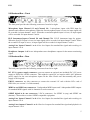
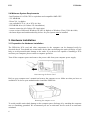
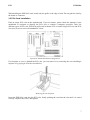
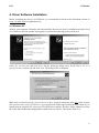
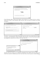
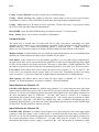
High Quality 8-in / 8-out
PCIe Audio Interface
User’s Guide
ESI - Copyright © 2009
Revision 1, April 2009
www.esi-audio.com
ESI
ESP1010e
INDEX
1. Introduction.................................................................................................................................. 4
2. Description of ESP1010e ............................................................................................................. 4
2.1 PCIe card.............................................................................................................................................................. 4
2.2 Breakout Box – Front........................................................................................................................................... 5
2.3 Breakout Box – Rear............................................................................................................................................ 5
2.4 Minimum System Requirements.......................................................................................................................... 6
3. Hardware Installation ................................................................................................................. 6
3.1 Preparation for Hardware Installation .................................................................................................................. 6
3.2 PCIe Card Installation.......................................................................................................................................... 7
4. Driver Software Installation ....................................................................................................... 9
4.1 Windows XP ........................................................................................................................................................ 9
4.2 Windows Vista................................................................................................................................................... 10
5. ESP1010e Control Panel............................................................................................................ 12
5.1 Pull-Down Menus .............................................................................................................................................. 12
5.2 Input Section ...................................................................................................................................................... 13
5.3 Output Section ................................................................................................................................................... 14
5.4 Digital Section ................................................................................................................................................... 14
5.5 DirectWIRE ....................................................................................................................................................... 15
6. Audio Applications..................................................................................................................... 17
6.1 Windows Multimedia Setup............................................................................................................................... 17
6.2 Cubase LE 4....................................................................................................................................................... 17
7. General Information .................................................................................................................. 18
3
ESI
ESP1010e
1. Introduction
Thank you for choosing the ESI ESP1010e, the perfect audio gear for multi channel recording
applications in your home studio and for home entertainment. The hardware integrates the latest
interface standard for extremely fast and reliable data transfer, more reliable and stable than
comparable FireWire or USB 2.0 interface solutions.
ESP1010e is equipped with 24-bit converters on up to 8 analog inputs, up to 8 analog outputs. Two
input connectors are equipped with microphone preamps with balanced XLR connectors and
switchable phantom power supply that can be used with high quality dynamic and condenser
microphones, in addition two Hi-Z inputs are provided to directly connect and use guitar input
signals. ESP1010e also provides a 24-bit 96kHz coaxial digital input and output, a 32 channel MIDI
I/O interface with 2 inputs and 2 outputs and full EWDM driver with DirectWIRE functionality.
All this makes ESP1010e a perfect multi channel recording solution for all the latest audio
applications – the system is simple to install and simple to use and is a great choice for you to build
a home studio around.
2. Description of ESP1010e
2.1 PCIe card
The ESP1010e PCIe card only has one single connector – EDI II. This connector is used to connect
the PCIe card with the 19" breakout box using the supplied cable.
Low Profile bracket
The ESP1010e PCIe card is a low profile card, that means it can
be installed in computer systems with lower height (the so-called
“low profile” standard). The hardware is supplied with an
additional smaller metal bracket that can be installed when
needed. To install it, you need to remove the standard bracket
using a screw driver to remove the two screws. Then use them to
install the other bracket.
4
ESI
ESP1010e
2.2 Breakout Box – Front
The front panel provides the following connectors from left to right:
Microphone Input Channel 1/2 and Channel 3/4: 2 microphone inputs with XLR input for
dynamic and condenser microphones. When the first microphone input is in use, its input signal will
be recorded via input channel 1 and 2. When the second microphone input is in use, its input signal
will be recorded via input channel 3 and 4.
Hi-Z Instrument Inputs Channel 5/6 and Channel 7/8: 2 Hi-Z instrument input for guitars.
When the first Hi-Z input is in use, its input signal will be recorded via input channel 5 and 6. When
the second Hi-Z input is in use, its input signal will be recorded via input channel 7 and 8.
Analog Line Inputs Channel 1 to 4: 4 line level inputs for standard line signal and recording via
input channel 1 to 4.
Headphone Outputs 1 & 2: two independent stereo headphone outputs for the master monitoring
signal.
2.3 Breakout Box – Rear
The back panel provides the following connectors from left to right:
DC 12V 1A power supply connector: you can connect an optional (not included) DC 12V power
supply to ESP1010e via this connector. This might be required if you require stable +48V phantom
power supply for the two microphone inputs on the front. Please note that normally this power
supply is not required.
EDI II connector: use this connector to connect the external 19" rack with the PCIe card of
ESP1010e (see section 2.1 of this manual).
MIDI in and MIDI out connectors: 2 independent MIDI inputs and 2 independent MIDI outputs
for standard MIDI signals with 16 channels for each connector.
S/PDIF digital in & out connectors: 2 RCA connectors, for S/PDIF in (top) and S/PDIF out
(bottom). Connect these to other S/PDIF compatible equipment.
Analog Line Inputs Channel 5 to 8: 4 line level inputs for standard line signal and recording via
input channel 5 to 8.
Analog Line Outputs Channel 1 to 8: 8 line level outputs for standard line signal and playback via
output channel 1 to 8.
5
ESI
ESP1010e
2.4 Minimum System Requirements
- Intel Pentium 4 1.0 GHz CPU or equivalent and compatible AMD CPU
- 512 MB RAM
- Direct X 8.1 or higher
- one available PCIe x1, x4 or PCIe x16 slot
- DVD-ROM drive (for Cubase LE 4 installation)
- internet connection (for Cubase LE 4 activation)
- recent version of Microsoft Windows XP (SP2 or higher) or Windows Vista (32-bit & 64-bit)
- the latest chipset and mainboard utility drivers for your system must be installed
3. Hardware Installation
3.1 Preparation for Hardware Installation
The ESP1010e PCIe card and other components in the computer can be damaged easily by
electrical shock. You should use an anti-static device that can discharge the static electricity of your
body to avoid potential static damage to the cards. If you do not feel capable of installing a PCIe
card into your computer please contact a computer specialist.
Turn off the computer power and remove the power cable from your computer power supply.
Disconnecting the Power Cord
Refer to your computer user’s manual and remove the computer cover. Make sure that you have an
available PCIe slot on your motherboard to install the ESP1010e.
Removing the computer cover
To avoid possible static shock damage to the computer parts, discharge it by touching the computer
case or something grounded. We recommend you use an anti-static device such as an anti-static
wristband.
6
ESI
ESP1010e
When holding the ESP1010e card, touch only the guide or the edge of card. Do not grab the card by
the board or connector.
3.2 PCIe Card Installation
Find an empty PCIe slot on the motherboard. If you are unsure, please check the manual of your
mainboard or computer to identify the PCIe slot, or consult a computer specialist. There are
different types of PCIe slot, ESP1010e will work in shorter PCIe x1 and in longer PCIe x4 and PCIe
x16 slots, however not in old standard PCI slots.
Typical PC Motherboard Slot Configuration
If a faceplate or cover is behind the PCIe slot, you can remove it by removing the screw holding it
in place or by prying it off with a screwdriver.
Removing the slot faceplate
Insert the ESP1010e card into the PCIe slot, firmly pushing the card into the slot until it is seated
securely. Replace the screw, and tighten.
7
ESI
ESP1010e
The ESP1010e PCIe card installed in a PCIe x1 slot, next to two standard PCI slots
Once finished, close the computer case. Now use the supplied EDI II cable to connect the
ESP1010e 19" rack with the card.
Connecting the EDI II cable to the ESP1010e PCIe card
Make sure the other end of the cable is properly connected to the EDI II connector on the 19" rack.
Caution: please make sure that the EDI II cable between the 19" rack and the PCIe card never
gets disconnected while your computer is powered on. Your system may crash and data loss may
occur. The EDI II cable is not intended and designed for connection while the computer is
switched on. As this is quite critical, we mention it again: never connect or disconnect the EDI II
cable while your computer is turned on.
8
ESI
ESP1010e
4. Driver Software Installation
Before installing the drivers of ESP1010e, we recommend to check on the download section of
www.esi-audio.com for updated drivers.
4.1 Windows XP
Turn on your computer. Windows will automatically detect a new device installation and the Found
New Hardware Wizard window will appear as seen on the following picture on the left.
Select No, not this time and click Next. On the following dialog select Install from a list or a
specific location (Advanced) and click Next. The dialog below will appear.
Make sure to select Search for the best driver in these locations and below that only select Include
this location in the search. Via Browse, you can select the folder that contains the driver data. If you
install from the original CD, select your CD-/DVD-drive and the \Windows folder. Otherwise select
the folder that contains the unzipped driver data from our website. Once done, click Next.
9
ESI
ESP1010e
Windows will now prompt you to confirm the Windows Logo testing in the Hardware Installation
dialog with Continue Anway before the driver installation proceeds. After some time, the
installation of the ESI ESP1010e Controller device will be completed and you need to click Finish.
Once this is done, the Found New Hardware Wizard will automatically appear again. Please follow
the exact steps one more time, to install a second ESI ESP1010e Controller device.
The Found New Hardware Wizard will then appear for a third time. Please follow all the steps once
more, to install the ESI ESP1010e Audio device. After that is finally confirmed on the last dialog
via Finish, the ESP1010e driver software has been completely installed. To confirm this, please
check if the ESI icon is displayed in the taskbar notification area as shown below.
If yes, the driver installation has been completed successfully. Note that on some systems the
computer has to be rebooted (Windows will display a message in that case) before everything is
completed.
4.2 Windows Vista
Turn on your computer. Windows will automatically detect a new device installation and the Found
New Hardware window will appear as seen on the following picture.
Select Locate and install driver software (recommended). Insert the driver CD only if you are
installing the original driver from the CD. If you are installing an updated driver from our website,
proceed by clicking on I don’t have the disc. Show me other options. on the following dialog.
10
ESI
ESP1010e
If the following window on the left will appears, click on Browse my computer for driver software
(advanced) in order to show Windows where the driver files are located. The dialog on the right
will appear.
Via Browse, you can select the folder that contains the driver data. If you install from the original
CD, select your CD-/DVD-drive and the \Windows folder. Otherwise select the folder that contains
the unzipped driver data from our website. Once done, click Next.
Windows will now prompt you to confirm the installation in the Windows Security dialog with
Install before the driver installation proceeds. After some time (on some systems it could really take
11
ESI
ESP1010e
a while), the installation of the ESI ESP1010e Controller driver will be completed and you need to
click Close.
To confirm the completion of the installation, please check if the ESI icon is displayed in the
taskbar notification area as shown below.
If yes, the driver installation has been completed successfully.
5. ESP1010e Control Panel
This chapter describes the ESP1010e Control Panel. To open the panel double
click on the ESI icon in the task notification area. The following dialog will
appear:
5.1 Pull-Down Menus
File – Exit: will close the ESP1010e control panel window but it will not shut down the control
panel. You can always launch control panel the by clicking ESI icon on the system tray.
Config – Mouse Wheel: controls the increment at which the volume is adjusted when using a
mouse wheel. The adjustment step is from 1 to 8.
Config – Latency: adjusts the latency (also often referred as buffer size) of ESP1010e. A lower
latency is achieved by selecting smaller sample size which is ideal for software synthesizer and
precise timing recording. However, the latency is also limited by your system performance. For
most recording applications, select a sample size between 64 ~ 512, select 256 or higher on slower
systems or at very high system load. Buffer size 48 is reserved only for very fast and reliable ASIO
driver environments on fast computer systems. Note that this value has to be setup before launching
any audio application using ESP1010e.
12
ESI
ESP1010e
Config – Factory Default: resets the control panel to default settings.
Config - Always On Top: this enables to place the control panel on top of every open window,
which makes it easy to work with ESP1010e and other audio applications simultaneously.
Config – Link: links the L-R faders for stereo operation. Unselect the entry, if you need to control
the levels of left and right channels independently.
DirectWIRE: opens the DirectWIRE dialog, described in section 5.5 of this manual.
Help – About: allows you to check current driver information.
5.2 Input Section
The input area is divided into 4 section from left to right, each allows controlling two input
channels; in total control over 8 input channels is possible. Each section from top down shows a
channel label (i.e. 1/2), a button for monitoring (MON), a gain knob (0db .. +24dB), input level
faders, two MUTE buttons, input level display in dB and input selection buttons at the bottom.
Monitor buttons: with this button you can enable the input monitoring for the corresponding input
channel pair. When enabled, the input signal is audible via the output.
Gain knobs: as the output level of a microphone typically is very low and requires amplification,
the gain knobs allow you to control the built-in amplifier in order to raise and match the input signal
in order for the signal to be further processed. The range is from 0dB to +24dB amplification. The
gain knobs only have an effect when the corresponding channel is set to MIC or to Hi-Z Instrument.
Level faders: these faders allow you to adjust the input level for inputs 1/2, 3/4, 5/6 and 7/8. The
levels can be set using the mouse, mouse wheel, or cursor keys. Depending on the Link setting
(refer to section 5.1), you can control left an right channels simultaneously or independently.
Mute buttons: this button allows you to mute the input signal on channel 1/2, 3/4, 5/6 or on
channel 7/8. When the button is red, mute is enabled – otherwise disabled.
Input Selection for Channel 1/2:
Line/Mic/+48V/Digital selection: by default, input channel 1/2 is processing the stereo line input
signal coming in from line inputs 1 and 2 (when LINE is selected) from the front panel of ESP1010e.
However, it can also be switched to process the mono input signal from a microphone connected to
the first microphone input of ESP1010e – for that, MIC must be selected. If a condenser
microphone that requires power supply is connected, the +48V switch must be enabled to enable
phantom power. Note that +48V should be enabled only after a condenser microphone has been
connected. Input channel 1/2 can also process the digital input signal from the coaxial S/PDIF input
of ESP1010e. For that, DIGITAL must be selected.
Input Selection for Channel 3/4:
Line/Mic/+48V selection: by default, input channel 3/4 is processing the stereo line input signal
coming in from line inputs 3 and 4 (when LINE is selected) from the front panel of ESP1010e.
However, it can also be switched to process the mono input signal from a microphone connected to
the second microphone input of ESP1010e – for that, MIC must be selected. If a condenser
microphone that requires power supply is connected, the +48V switch must be enabled to enable
13
ESI
ESP1010e
phantom power. Note that +48V should be enabled only after a condenser microphone has been
connected.
Input Selection for Channel 5/6:
Line/Hi-Z Instrument selection: by default, input channel 5/6 is processing the stereo line input
signal coming in from line inputs 5 and 6 (when LINE is selected) from the back panel of ESP1010e.
However, it can also be switched to process the mono input signal from a guitar connected to the
first Hi-Z input on the front panel of ESP1010e – for that, Hi-Z Instrument must be selected.
Input Selection for Channel 7/8:
Line/Hi-Z Instrument selection: by default, input channel 7/8 is processing the stereo line input
signal coming in from line inputs 7 and 8 (when LINE is selected) from the back panel of ESP1010e.
However, it can also be switched to process the mono input signal from a guitar connected to the
second Hi-Z input on the front panel of ESP1010e – for that, Hi-Z Instrument must be selected.
5.3 Output Section
H.P./Mix buttons: with these buttons it is possible mix the output 1/2, 3/4, 5/6 and 7/8 signals to
each other. This is especially important if you want to listen to the same signal played through only
one channel pair on both outputs, especially with headphones connected to one of the headphone
outputs on the front panel of ESP1010e. When one of the buttons is enabled, a colored line on the
screen will display that the signal is transferred to the other output channel.
Level knobs: controls the level for mixed signal to adjust the level that you wish to send to the
other channel. Make sure not to confuse the mix knobs with the gain knobs in the input section.
Level faders: these faders allow you to adjust the playback level for the analog output 1/2, 3/4, 5/6
and 7/8 signals. The levels can be set using the mouse, mouse wheel, or cursor keys. Depending on
the Link setting (refer to section 5.1), you can control left an right channels simultaneously or
independently.
Mute buttons: this button allows you to mute the output signal on each individual channel. When
the button is red, mute is enabled – otherwise disabled.
5.4 Digital Section
Digital Out section: here you can select the source for the optical and coaxial S/PDIF output It can
either be from output 1/2 or from output 3/4, depending on the selection. The ESP1010e S/PDIF
output is capable to send out professional (PRO) and consumer (CON) status bits, depending on the
selection. Some digital devices will only process either one of the two signal types on their S/PDIF
input.
Digital In section: allows you to select the digital input source. When this is set to Loopback, the
digital input signal will be internally taken from the S/PDIF transmitter – this means that you can
internally record and process 1:1 copies on a pure hardware level inside the ESP1010e hardware.
The recommended and default setting is External, as it processes the signal from the physical
coaxial S/PDIF input from ESP1010e instead. Below that, the Status area displays the current
S/PDIF input signal state.
14
ESI
ESP1010e
5.5 DirectWIRE
What is DirectWIRE?
DirectWIRE is a driver technology, developed by ESI, which can be used for routing audio streams
internally within applications using EWDM Audio MIDI Drivers exclusively developed by ESI.
With the DirectWIRE router, an application can record from other application’s audio outputs
without external wiring or any loss of data when they are running at the same time.
DirectWIRE also allows you to easily rip any audio stream in real time by transferring data thru
DirectWIRE from MP3s, live On-line Broadcast and On-demand content, and more.
DirectWIRE Panel
Click on DirectWIRE on the ESP1010e control panel. The DirectWIRE dialog as shown below will
appear. DirectWIRE digital virtual wiring technology, developed by ESI, routes audio streams
internally within applications using standard audio drivers such as WDM, ASIO and MME, even
when they are running at the same time.
The number on the row represents the input or output port. The columns represent ins and outs (on
and off) of the respected drivers. Patch the virtual cables from one point to another as you drag your
mouse point.
INPUT section: It's used to route signals from the card's hardware inputs.
MME section represents general application's I/O: Ex.) WinAmp, WaveLab (non ASIO mode),
Cakewalk, Audition, Vegas, etc.
WDM section represents Multi-MME application’s I/O: Ex.) SONAR (when using WDM/KS),
PowerDVD, WinDVD, etc.
ASIO section represents ASIO application’s I/O: Ex.) Cubase, Logic, Reason, Nuendo, SONAR
(when using ASIO), Samplitude, etc.
GSIF section represents GSIF application like GigaStudio.
Note that some applications support multiple driver modes.
15
ESI
ESP1010e
DirectWIRE Examples
Example 1. Recording from WinAmp (MME) to WaveLab (MME).
If you want to record what's played back in WinAmp, but don't want to hear the sound, you should
click the OUT button in the MME section so it'll change to OFF.
Example 2. Recording from WinAmp (MME) to Example 3. Recording from WinAmp (MME) to
Cubase, Logic, Nuendo (ASIO).
SONAR (WDM).
Example 4. Recording from GigaStudio (GSIF)
to SONAR (WDM).
16
Example 5. Recording from GigaStudio (GSIF)
to Cubase (ASIO).
ESI
ESP1010e
6. Audio Applications
This chapter contains basic configuration examples for some software applications. Please also refer
to the manual of the audio software you use for detailed information.
6.1 Windows Multimedia Setup
The Windows multimedia setup is required if you want to use your ESP1010e as the main sound
device for Windows multimedia applications. Go to My computer-> Control panel -> Sounds and
Audio Device Properties -> Audio. Select the ESP1010e entry as your playback device to make
sure that all standard signals are played via the ESP1010e hardware.
Please note that some advanced properties buttons in this area will be grayed out because some of
the mixer features of ESP1010e are not compatible with the functions provided by the Windows
default mixer that was designed for consumer audio hardware. However, this does not mean you do
not have any advanced options - the ESP1010e control panel described in the previous chapter
includes all professional audio features that you might need and which are simply not always
compatible with the basic mixer control from Windows.
6.2 Cubase LE 4
ESP1010e ships with a DVD-ROM with Cubase LE 4 from Steinberg. If you are using a different
recording software, you can skip this section.
Installation
To install Cubase LE 4, insert the DVD-ROM into the DVD-ROM drive of your computer. Under
Windows, the installation will normally start automatically – if not, you can launch it manually by
starting the installer from the DVD-ROM drive.
To proceed with the installation, follow all instructions on screen. During the installation the
Syncrosoft License Control software will be installed as well. To use Cubase LE 4 for more than 30
days, you need to activate it with this software via the internet. This means that you need an active
internet connection on the computer you are installing Cubase LE 4. We recommend you to activate
the software as early as possible.
Initial Setup
As most digital audio applications, Cubase LE 4 requires some initial configuration, before it can be
used properly with a new audio interface like ESP1010e. Start Cubase LE 4 and select Device Setup
from the Devices menu. Select VST Audio System on the tree structure on the left part of the
window and then make sure to select ESI ESP1010e ASIO as ASIO Driver entry. You can verify
your selection by selecting the ESI ESP1010e device on the left. The dialog, now lists all input and
output channels. Note that the Control Panel button has no effect. Confirm your changes by
clicking OK.
After that its time to select the input and output channels. From the Devices menu, select VST
Connection. The VST Connections window appears. Configure your input bus in the Inputs tab and
your output bus under Outputs. A bus can be either mono or stereo and added with Add Bus.
17
ESI
ESP1010e
After that you can start using Cubase LE 4 by opening an existing project or creating a new project.
The input and output busses you have created can be assigned to the individual tracks of your
project.
7. General Information
Trademarks
ESI, and ESP1010e are trademarks of EGOSYS, Inc. and ESI Audiotechnik GmbH. Windows is a
trademark of Microsoft Corporation. Other product and brand names are trademarks or registered
trademarks of their respective companies.
The FCC and CE Regulation Warning
This device complies with Part 15 of the FCC Rules. Operation is subject to the following two
conditions : (1) this device may not cause harmful interference, and (2) this device must accept any
interference received, including interference that may cause undesired operation. Caution : Any
changes or modifications in construction of this device with are not expressly approved by the party
responsible for compliance, could void the user's authority to operate equipment.
Note: This equipment has been tested and found to comply with the limits for a Class A digital
device, pursuant to Part 15 of the FCC Rules. These limits are designed to provide reasonable
protection against harmful interference when the equipment is operated in a commercial
environment. This equipment generates, uses, and can radiate radio frequency energy and, if not
installed and used in accordance with the instruction manual, may cause harmful interference to
radio communications. Operation of this equipment in a residential area is likely to cause harmful
interference in which case the user will be required to correct the interference at his own expense. If
necessary, consult an experienced radio/television technician for additional suggestions.
Correspondence
For technical support inquiries, contact your nearest dealer, local distributor or ESI support online at
www.esi-audio.com.
Disclaimer
All features and specifications subject to change without notice.
Parts of this manual are continually being updated. Please check our web site www.esi-audio.com
occasionally for the most recent update information.
18