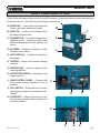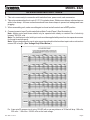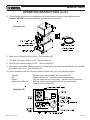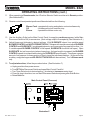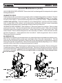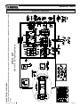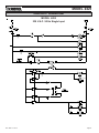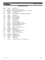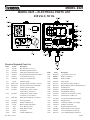
1
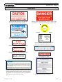
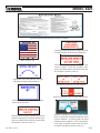
OWNERS MANUAL
MODEL #425
55 YEARS OF AMERICAN INGENUITY
KRENDL MACHINE COMPANY • 1201 SPENCERVILLE AVE
DELPHOS, OHIO 45833 • TELEPHONE 419-692-3060 • FAX 419-695-9301
E - MAIL: [email protected] • WEB SITE: www.krendlmachine.com
CONGRATULATIONS ON YOUR PURCHASE OF KRENDL EQUIPMENT
MODEL #425
OWNER'S MANUAL
FOR ASSURED SAFETY AND CONFIDENCE, PLEASE READ THIS
MANUAL CAREFULLY BEFORE INSTALLING AND OPERATING
YOUR MACHINE.
E-MAIL ADDRESS IS: [email protected]
WEB SITE IS: www.krendlmachine.com
Table of Contents
PAGE
INTRODUCTION. . . . . . . . . . . . . . . . . . . . . . . . . . . . . . . . .
1
GENERAL SAFETY INFORMATION. . . . . . . . . . . . . . . . . . 2-3
DECALS . . . . . . . . . . . . . . . . . . . . . . . . . . . . . . . . . . . . . . 4-5
WARRANTY . . . . . . . . . . . . . . . . . . . . . . . . . . . . . . . . . . . .
6
RETURNED GOODS PROCEDURE and SPECIFICATIONS
7
BASIC COMPONENTS. . . . . . . . . . . . . . . . . . . . . . . . . . . .
8
OPERATING INSTRUCTIONS . . . . . . . . . . . . . . . . . . . . . . 9-11
TROUBLESHOOTING . . . . . . . . . . . . . . . . . . . . . . . . . . . .
12
GENERAL MAINTENANCE . . . . . . . . . . . . . . . . . . . . . . . . . 13-15
ELECTRICAL . . . . . . . . . . . . . . . . . . . . . . . . . . . . . . . . . . .
16
LADDER DIAGRAM . . . . . . . . . . . . . . . . . . . . . . . . . . . . . .
17
PARTS LIST . . . . . . . . . . . . . . . . . . . . . . . . . . . . . . . . . . . . 18-21
GLOSSARY . . . . . . . . . . . . . . . . . . . . . . . . . . . . . . . . . . . .
22
SERVICE RECORD. . . . . . . . . . . . . . . . . . . . . . . . . . . . . .
23
MODEL #425
INTRODUCTION
Thank you for purchasing a KRENDL INSULATION MOVING MACHINE. With over fifty-five years
experience in manufacturing insulation moving equipment, we have designed and built your machine with
the highest quality to provide years of reliable service.
This manual has been prepared to help you obtain the maximum efficiency and service from your Krendl
equipment. The machine is designed to condition and apply insulation with the utmost in dependable
performance. Our primary objective is to build equipment which will provide complete satisfaction so
that you may confidently recommend Krendl to others.
We do not manufacture or sell insulation. Our interest lies only in the proper performance of the equipment we
manufacture. We make no recommendations or guarantees concerning various insulations.
CAUTION:
This manual contains important information regarding the safe assembly and operation of your
machine. We urge you to read it carefully and follow the instructions provided. If your questions are not
answered in this manual, may we hear from you? We want you to be able to operate this unit safely
and confidently.
UNPACKING: Store and unpack carton with correct side up. Unpack your machine IMMEDIATELY and
check for damage in shipping. Place any damage claim with delivering carrier, saving all packing
materials for inspection. Our warranty covers manufacturer's defects only. DO NOT return to shipper.
FILL IN AND RETAIN:
Krendl Machine Company
1201 Spencerville Ave.
Delphos, Ohio 45833 U.S.A.
Telephone:
Fax:
E-mail:
Web Site:
419-692-3060
419-695-9301
[email protected]
www.krendlmachine.com
For your protection in the event of theft or loss, please fill in the information requested for your own
records. This information will be needed for in-warranty repairs. You may also want to attach a copy of
your invoice.
Machine model number_____________
Blower motor manufacturer
_
Serial number
Gear motor manufacturer
_
_
Blower(s) serial number(s)___________
Gear motor serial number________________________
Supplier_________________________
Date of purchase
______________
The model and machine serial numbers are located on the hopper of the machine unit. The blower and
gearmotor serial numbers are located on the motor housing of each unit.
Rev. Date: 12-15-14
Page 1
MODEL #425
GENERAL SAFETY INFORMATION
Important: Read all instructions before operating this unit. This equipment can be potentially
dangerous and must be used in strict accordance with instructions.
Disclaimer Notice: The manufacturer will not be legally responsible for any injury or damage resulting
from the improper use of this equipment or the failure to follow instructions.
Unpacking
Handle cartons with care to avoid damage from dropping or bumping. Store and unpack cartons with the
correct side up. Completely remove machine from the packaging and from any shipping pallet or skid to
which it might be attached. In addition, completely remove all shipping materials from inside the machine
including wheel package, manual, ect....
General Safety
1. Read this manual carefully and become familiar with your machine unit. Know its applications,
limitations, and any hazards involved.
2. This machine was designed and manufactured for specific applications. Do not attempt to
modify the unit or use it for any application it was not designed for. If you have any questions
about your intended use or the machines suitability, ask your dealer/distributor or consult the
factory. The manufacturers' could not possibly anticipate every circumstance that might involve
a hazard. For that reason, warnings in the manual and warning tags or decals affixed to the unit,
are not all-inclusive. If you intend to handle, operate, or service the unit by a procedure or method
not specifically recommended by the manufacturer, first make sure that such a procedure or
method will not render this equipment unsafe or pose a threat to you and others.
Electrical Safety
• The National Electric Code (NEC) in the United States and many international electrical codes require
frame and external electrically conductive parts of this machine to be properly connected to an approved
earth ground. Local electrical codes may also require proper grounding of machine. Consult with local
electricians for grounding requirements in your area.
• Never handle any kind of electrical cord or device while standing in water, while barefoot or while hands
or feet are wet. Dangerous electrical shock will result.
• Use a ground fault circuit interrupter (GFCI) in any damp or highly conductive area. (metal decking or steel work)
• Reference NFPA 79, 70E, or OSHA safe work practices when performing energized work procedures.
Rev. Date: 12-15-14
Page 2
MODEL #425
Safety/Caution
• Be Safe - Keep away from moving parts.
• Be Safe - Make sure all guards and hopper bar are in proper place before operating machine. Guards
and safety devices/switches should not be removed, modified or by-passed. Hands should
never pass below hopper bar.
• Be Safe - Do not remove motors or lift hopper when unit is connected to power supply.
• Be Safe - Make sure machine is properly grounded. Protect all electrical supply cords from sharp
objects, moisture, and other potentially hazardous materials. Keep power cords in good
repair. Electrical service must be performed by a qualified electrician.
• Be Safe - Disconnect power supply before inspecting or adjusting unit.
• Be Safe - Consult a qualified technician to answer questions before attempting to operate, or injury may
result.
• Be Safe - Do not operate machine alone.
• Be Safe - Do not leave machine unattended and energized.
• Be Safe - Turn machine off and disconnect electricity before clearing and feeding jam or attempting to
remove any object dropped in the hopper.
• Be Safe - Keep hands, loose clothing, jewelry and hair away from agitators, gears, chains and other
moving parts.
• Be Safe - Use proper lifting when moving insulation and loading machine.
• Be Safe - Keep work area clear of debris.
• Be Safe - Wear proper safety equipment, including protective gear, such as respirators, eye and ear
protection.
• Be Safe - Violation of the Owner's Manual or safety precautions may void warranty.
Make Sure!
• Hopper is empty of foreign objects before starting.
• Adequate electrical power is supplied or damage to unit will result.
• Blower filter is kept clean and in place when blower is on.
• Machine is turned off immediately if hose is plugged, or blower will overheat.
• Machine must be on before adding insulation.
• Blower(s) must be on, when agitators are running, or machine will bind.
• Agitator motor is not run with hopper empty for more than a few minutes, or damage to seals will result.
• Sprockets, chains, belts and pulleys are correctly aligned and tensioned.
• Pieces of bag are not left in the machine as this can bind and stall your machine.
• This machine should only be used with good quality insulations that are dry, undamaged and that meet
a certain industry specification or quality standards.
Rev. Date: 12-15-14
Page 3
MODEL #425
DECALS
Keeping the filter clean will result in longer
blower life and better performances.
Rotating parts can be dangerous! You can snag clothes,
hair, hands, etc. This can cause serious injury or death.
Emergency stop button for machine.
Manufacturer information is provided here
along with machine model, and serial number.
Indicates that the electrical box on the machine is in compliance with UL codes.
Specifies the voltage this outlet is rated for.
Identifies position of material feed gate.
Rotating parts will be moving in this direction.
KMC-01234
Reset button for motor.
Part number for identification and tracking.
Identifies what type of insulation should be used with this
machine and that the manual should be read before operating. Warns to be careful around electrical components!
This can cause serious injury or death.
Rev. Date: 12-15-14
General safety information intended to reduce
the risk of serious injury or death
Page 4
MODEL #425
Operating and troubleshooting instructions provided here.
Operating machine at specified voltage will result
in longer machine life and better performance.
Made in the U.S.A.
Indicates that this outlet is intended for only the
wireless remote. Each time machine cycle
starts, an audible alarm warns the operator that
the machine is about to come on.
Opens and closes the material feed gate
which in turn controls the production.
Indicates the input power of the machine.
Indicates if blower is off, on, or on with agitator.
Indicates which employee inspected equipment and on what date.
Indicates that this outlet is intended for only the
remote control outlet. Each time machine cycle
starts, an audible alarm warns the operator that
the machine is about to come on.
Rev. Date: 12-15-14
Identifies if machine is in remote mode, manual
mode, or off position. In manual mode this switch
operates machine. In remote mode the hand
pendant operates machine. Each time machine
cycle starts, an audible alarm warns the operator that the machine is about to come on.
Page 5
MODEL #425
WARRANTY:
Krendl Machine Company (Company) warrants to each original purchaser (Buyer) of its
machines that such products will be free of manufacturing defects for a period of 2 years from
the date of shipment to the Buyer. (This does not include accessories, pumps, blowers, wall
scrubbers, etc.)
No warranty is made with respect to:
1. Components or accessories manufactured and warranted by others. Warranties for
purchased component parts as supplied from vendor such as engine, electric motor,
blower, gearbox, transmission, etc., if furnished by the manufacturer of the component, are
on file at the Company’s main office and copies will be furnished at request of Buyer.
Component(s), shipping costs prepaid, shall be sent to Company who in turn shall forward
to vendor for evaluation and warranty determination.
2. Any defect caused by repair, alteration and/or adjustment performed by Buyer or customer/
vendor of Buyer without the express written authorization of the Company.
3. The labor costs of replacing parts by parties other than the Company.
4. Any machine that has not been operated and/or maintained in accordance with normal
industry practice and the written recommendations of the Company. (e.g. machine operated with an improperly sized, worn or damaged hose, improper or inattention to preventative maintenance, etc.)
5. The product has been subjected to misuse, negligence or accident or results of any
application or use of the blowing equipment not in accordance with the Company recommendations.
This limited warranty does not cover the free replacement of component parts that become
inoperative due to wear and usage and need to be replaced on a regular basis, including but not
limited to: airlock seal(s), agitator(s), shredder(s), auger(s), fuse(s), switch(es), clutch(es), hose(s),
shaft seal(s), chain(s), belt(s), sprocket(s), pulley(s), bearing(s), cable(s), battery(ies), filter(s),
fan(s), etc.
The Company’s obligation under this warranty is limited to repairing or replacing (at Company
option) any part that is determined by the Company to be suffering from a manufacturing defect.
The Company (at Company option) will provide any required parts and labor to the Buyer. If the
equipment or parts must be returned to the Company for repair, all transportation costs shall be
the Buyer’s responsibility.
THIS LIMITED WARRANTY IS EXPRESSLY IN LIEU OF ANY OTHER GUARANTEES AND / OR
WARRANTIES, ORAL OR WRITTEN, EXPRESSED OR IMPLIED, INCLUDING WITHOUT LIMITATION, THE IMPLIED WARRANTY OF MERCHANTABILITY. NO WARRANTY, EXPRESS OR
IMPLIED, OTHER THAN THE AFORESAID WARRANTY IS MADE OR AUTHORIZED BY COMPANY. COMPANY SHALL NOT BE LIABLE FOR ANY DIRECT, INDIRECT, INCIDENTAL OR
CONSEQUENTIAL DAMAGES TO PROPERTY OR INJURY TO ANY PERSON OR COSTS ASSOCIATED WITH LOSS OF PRODUCTION RESULTING IN LOSS OF REVENUE, PROFITS OR LOSS
OF EQUIPMENT THROUGH THE USE OF THIS EQUIPMENT.
Note: Special job circumstances incurring costs for specialized repair and next day delivery
of parts will not be reimbursed by the manufacturer unless authorized by factory.
Rev. Date: 12-15-14
Page 6
MODEL #425
RETURNED GOODS PROCEDURE:
IF MACHINE WAS NOT PURCHASED DIRECTLY FROM KRENDL MACHINE COMPANY, CONTACT
YOUR SUPPLIER / DISTRIBUTOR.
When returning products to Krendl for repair, first obtain a return goods authorization, at which time you
will be given shipping instructions. The product must be shipped PREPAID:
Krendl Machine Company
1201 Spencerville Ave.
Delphos, Ohio 45833 U.S.A.
Telephone:
Fax:
E-mail:
Web Site:
419-692-3060
419-695-9301
[email protected]
www.krendlmachine.com
Once the unit is received, it will be inspected. In-warranty units will be repaired and returned
immediately. An estimate of repair charges will be provided for out-of-warranty units.
SPECIFICATIONS
MODEL#:
425
HEIGHT:
WIDTH (DEPTH):
LENGTH:
WEIGHT:
ELECTRICAL:
BLOWER VOLUME:
BLOWER PRESSURE:
HOSE OUTPUT:
57 1/2" (146 cm)
36" (91 cm)
21" (53 cm)
225 pounds (102 kg)
230VAC, 16 amp, S.I.
140 CFM
4.5 PSI maximum
2.5” diameter
MAXIMUM FEED RATES:
CELLULOSE:
1200 lbs/hr (545 kg/hr)
FIBERGLASS:
300 lbs/hr (136 kg/hr)
MINERAL FIBER: 800 lbs/hr (363 kg/hr)
WARNING: Recommended hose size, type and length must be used to achieve maximum results. Krendl
cannot guarantee performance of the machine if hoses are undersized, worn, damaged, or
hoses other than those we recommend are used.
BEFORE YOU RUN THIS MACHINE...PLEASE READ THE REST OF THIS MANUAL!!
Rev. Date: 12-15-14
Page 7
MODEL #425
BASIC COMPONENTS: #425
This is a view of the basic components of your #425 machine. It shows the location of each item and gives
the function of each. Use this as a guide throughout the manual.
A) BASE UNIT — Lower frame unit supporting
blower, gearmotor, airlock and hopper.
H
J
B) AIRLOCK — Traps air and insulation while
providing a metered flow.
C) GEAR MOTOR — Provides driving power of
agitation system. Increases output power
while decreasing speed of the agitators and
airlock.
F
D) BLOWER — Creates air pressure to blow
insulation out of airlock.
A
I
E) AGITATORS (2) — Conditions insulation in
the hopper.
F) HOPPER — Upper unit of machine holding
insulation.
G) HOPPER BAR — Hinders operators from
reaching agitators.
H) HOPPER EXTENSION — Increases overall
hopper capacity.
I) MAIN CONTROL PANEL — Connects with
main power, allowing operation of unit at
machine.
C
J) KILL SWITCH — Safety device for immediate stopping of machine. (Located on electrical box)
D
B
K) SLIDEGATE — Meters the amount of insulation dropping into airlock by controlling size
of airlock opening
G
E
Rev. Date: 12-15-14
K
E
Page 8
MODEL #425
OPERATING INSTRUCTIONS
1. This unit comes ready for connection with insulation hose, power cords, and accessories.
2. This unit provides a direct hook-up to 2 1/2" I.D. insulation hose. Slide hose on blower outlet and secure
with a hose clamp. All hose connections should have hose clamps to prevent air leakage and hose
plugging.
3. When assembling unit, make sure slidegate is closed and all controls are in OFF position.
4. Connect power to Input Cords located below Main Control Panel. (See Illustration A.)
Note: Agitator motor and blower should only be operated with steady or constant flow of electricity
between 220-230 volts.
Note: For double input units, both Input cords must be supplied with power from two separate sources
for the unit to work properly.
Note: When using extension cords, wire gauge size should not be less than input cord on unit and not
exceed 50' in length. (See Voltage Drop Chart Below.)
Ex: A two-wire 20-ampere circuit using 12 AWG with a one-way distance of 25 feet will drop 1.98 volts;
230 volts - 1.98 volts = 228.02 volts as the load voltage.
Rev. Date: 12-15-14
Page 9
MODEL #425
OPERATING INSTRUCTIONS (cont.)
5. The first bag of insulation in the hopper should be well broken by hand to assist agitator action.
Caution: NEVER force-feed material by pushing down on insulation.
(Illustration A)
6. Make sure Kill Switch is out by pulling. (See Illustration B.)
7. Turn Main Disconnect Switch to ON. (See Illustration B.)
8. Set 4-Position Selector switch to OFF. (See Illustration B.)
9. Press green start button. Machine will not run unless button is pressed after Kill Switch is out and Main
disconnect switch is on. (See Illustration B.)
10. Select operating mode on 4-Position Selector Switch from one of the following options:
Remote:
Off:
Blower:
Agitator-Feed/Blower:
Remote control hand pendant will control machine.
Machine will not run. (overrides remote hand pendant)
Only the blower will run continuously. (manual control at machine)
Both the blower and the agitator-feed will run continuously.
(manual control at machine)
(Illustration B)
Rev. Date: 12-15-14
Page 10
MODEL #425
OPERATING INSTRUCTIONS (cont.)
11. When operating in Remote mode, the 4-Position Selector Switch must be set to Remote position.
(See Illustration B.)
12. Remote control hand pendant positions will be selected from the following:
Blower-Feed - operates both motor and agitator motor simultaneously
Off
- (middle position) all functions stop
Blower
- operates the blower motor only
13. Use the Auxiliary Outlet on the Main Control Panel for supplying continuous power (while Main
Disconnect Switch is ON) to accessories. (Note voltage output on receptacle) (See Illustration A.)
14. Adjust blower and slidegate to desired settings. With SLIDEGATE closed, turn variable speed
BLOWER CONTROL and AGITATOR MOTOR ON. Fill hopper with insulation and adjust BLOWER
CONTROL and SLIDEGATE. In making adjustments, move one control in proportion to other. (i.e.
If variable speed BLOWER CONTROL is half-speed, SLIDEGATE should be half open.) Open
SLIDEGATE, but not beyond point where hose plugs. As hose length is increased, the BLOWER
CONTROL speed is increased while closing the SLIDEGATE proportionally. This allows a greater
amount of air pressure for lesser portion of fiber to travel the increased distance. (At the end of the
workday, empty the hopper and BLOW OUT THE HOSE with the machine.) Turn to Blower mode
only.
15. To adjust alarm time, follow the procedure below: (See Illustration C.)
a. Unplug machine from power source.
b. Turn OFF Main Disconnect Switch and open Main Control Panel lid.
c. Turn Timer Relay knob to desired setting. (clockwise to increase warning time)
d. Close lid, plug in machine, turn on Main Disconnect Switch and press green Start Button.
e. Retest Machine.
Main Control Panel (Overseas)
Illustration C
Rev. Date: 12-15-14
Page 11
MODEL #425
TROUBLESHOOTING
IMPORTANT: DO NOT attempt to service unit. (Contact your dealer for further information.)
1. Loud knocking sound:
a. Unplug power supply.
b. Check machine agitators and airlock for foreign objects.
2. Poor output from machine or uneven flow through hose:
a. Open SLIDEGATE.
b. Check for material bridging in hopper.
c. Voltage may be low, try another electrical source. Use proper wire size for extension cord.
d. Worn or damaged rubber airlock seals.
3. Too much dust on open blow:
a. Open SLIDEGATE.
b. Turn BLOWER CONTROL down. (See Illustration B.)
4. BLOWER MOTOR running hot:
a. Clean filter. Blow out surrounding area with air hose. (See Illustration A.)
b. Check for restriction in blowing hose.
5. AGITATOR MOTOR running hot:
a. Blow out the air hose as needed.
b. Low voltage can cause this condition. Try another electrical source.
c. Debris jamming airlock. UNPLUG power supply. Rotate airlock manually and clean out.
d. Check bearing for stiffness or seize up. Grease if needed.
Rev. Date: 12-15-14
Page 12
MODEL #425
GENERAL MAINTENANCE
Periodic preventive maintenance will add years of life to your equipment. Reviewing the information in
this manual will go a long way in reducing downtime. Remove hopper for easy maintenance of lower
base unit.
KEEP CLEAN: During operation, keep material from accumulating on Blower Filter. Always keep Filter
in place while operating machine. After each use, remove insulation from hopper and blow out hose.
AIRLOCK:
SEAL REPLACEMENT: The purpose of the airlock seal is to
trap air and insulation until it rotates 180O to the 6:00 o'clock
position. At this point, insulation is pushed by air from the
blower, out of the chamber. Worn or damaged seals allow air
and insulation to escape back into hopper, thus reducing production and coverage. When it is necessary to replace seals,
follow these directions:
Airlock rotor plates that are damaged (bent) will need replaced.
(Refer to Rotor Replacement below.) Take out rubber seal by
removing the three plate fastening bolts and top plate. Install
new seal. Seal should be inserted tight against the rotor plate,
pressing the lower tabs of seal down under the adjacent seal
with a flat blade screwdriver. (See Illustration D) Before tightening bolts make sure all bolt holes are aligned while each side of
seal is equally pressed against the end plates. Seal should be
bent backwards for counterclockwise rotation.
AIRLOCK REPLACEMENT:
1. Remove the chain guard, chain, and hose from airlock.
2. Lay machine down and remove bottom guard and two bolts
that secure airlock to machine. Take note of electrical connections and unhook gearmotor drive wires.
3. Remove airlock from machine.
4. Remove top plate and seal from rotor. Check seal and top
plate for wear and/or damage. (See Illustration E)
5. Remove gear motor and bearings from old airlock.
6. Install gearmotor and bearings on new airlock. Tighten set
screws on locking collar of bearings. (See Illustration E)
7. Install seal and top plate. As seal and top plate are installed, press bottom tab of seal under adjacent seal with
flat blade screwdriver. (See Illustration D)
8. Install weather stripping on top outer edge of airlock. (See
Illustration E)
9. Place airlock back into machine and reattach with bolts.
Reinstall chain and sprocket. NOTE: When inserting
airlock back into machine, make sure back lip of airlock
slides into airlock track then fasten bolts. Also, make sure
slidegate is in slidegate track.
Rev. Date: 12-15-14
Illustration D
Illustration E
Page 13
MODEL #425
General Maintenance (cont.)
Make sure seal and top plate are assembled on correct side of rotor plate before assembling in
airlock. Seal should press backward towards top plate when installed correctly into airlock chamber.
The airlock runs counterclockwise viewing it from the sprocket drive shaft. (See Illustration A)
Caution: If installed improperly, damage to seals will result and put undue stress on agitator motor.
This causes overheating and poor production. Seal should be bent backward to allow for a
counterclockwise rotation of rotor.
CHAIN: (#40 Nickel Plated)
ADJUSTMENT: A smooth operating chain drive should have a slight sag on the idler side of the chain.
New chains should be installed under slight tension as they will elongate a small amount due to seating of
pins and bushings during the first few days of operation. Excessive chain tension or loose chain will
cause shortened life of bearings, chain, and sprocket. Chain should be kept in good condition by proper
lubrication (dry film lubricant Dow 321) and occasional cleaning. Soaking chain in container of 10 weight
oil will provide for internal lubrication of pins and bushings. However, excess oil must be drained and
wiped away as excessive lubrication will cause insulation accumulation on chain. Worn out chain should
be replaced. When chain is replaced, worn sprockets should also be replaced, preventing further
damage to new chain.
SPROCKETS:
CHECK SPROCKETS FOR WEAR. Misalignment and/or loose sprockets and improper chain tension
causes the premature wear of chain and sprockets. All sprockets, except the idler sprocket, have been
secured with a medium grade Loctite (general purpose thread locker), to prevent gradual movement. The
set screws and key are also inserted with a medium grade Loctite. If sprocket is difficult to remove, it may
be heated with a propane torch to loosen.
Caution: Do not overheat sprocket or damage to bearing will result. A pulley or bearing puller can
then be used to remove the sprocket and key. Replace new sprocket on shaft with key and medium
grade Loctite applied to shaft. Align sprocket with corresponding sprocket, using a straightedge
placed along face of teeth and tighten set screw. Gearmotor sprocket does not require Loctite.
BEARINGS:
AGITATOR BEARINGS in base unit are prelubricated, double-sealed, self aligning ball bearings. No
lubrication is necessary. If bearings produce noise or heat (too-hot-to-touch), replace the bearings.
AGITATOR BEARING REPLACEMENT: Spray area with rust penetrant (WD-40). Remove sprocket
(See SPROCKET section above). Remove the two bolts from bearing flange and outer flange from
bearing insert. Loosen set screws on bearing hub at each end of agitator shaft. Since all set screws are
installed with a medium grade Locktite, a propane hand torch may be used to assist in removing them.
Do not overheat unit, causing shaft to expand. Using a rubber mallet, drive agitator shaft an inch in one
direction, creating a space between hopper and bearing unit. A bearing puller can then be used to
remove the bearing. Eliminate any metal burrs from shaft with file and install new bearings with felt seals.
Use a medium grade Loctite on set screws before securing bearing to shaft.
AIRLOCK BEARINGS are prelubricated, double sealed, self aligning ball bearings. Lubrication is
required at three month intervals of normal running time, or sooner if bearings produce a noise or become
too-hot-to-touch. Relubrication at the grease fittings is done with a lithium base grease conforming to a
NLGI GRADE TWO consistency. The grease should be pumped in slowly until a slight bead forms around
the seals. This bead, in addition to acting as an indicator of adequate lubrication, provides additional
protection against the entry of foreign matter. Important: If a slight bead does not form, indicating a
failure of lubrication, or if bearing shows signs of wear, replace bearing.
Rev. Date: 12-15-14
Page 14
MODEL #425
General Maintenance (cont.)
AIRLOCK BEARING REPLACEMENT: Remove two bolts from bearing and follow steps above for agitator
bearing replacement.
GEARMOTOR DRIVE:
If drive motor runs hot, or unit does not run properly, refer to troubleshooting sections of manual. The drive
motor should start quickly and run smoothly. If not, shut motor off immediately and check for low voltage,
incorrect power supply, or misconnected wiring which could cause motor failure. These conditions
void the motor warranty. Overload conditions such as bearing failure, sprocket and chain misalignment, or gear failure in the reducer can be detected by checking the electrical current (amperage)
compared with nameplate current (amperage) located on the body of the motor.
GEARMOTOR REPLACEMENT: (See Illustration F) Disconnect power from machine. Remove chain
guard and drive chain. Flip base unit upside down and remove bottom guard. Take note of electrical
connections and unhook gearmotor drive wires. Loosen hose clamp on rear airlock input tube. Slide
hose off airlock. Remove airlock and gearmotor drive assembly out of base. Loosen set screw and take
sprocket off gearmotor. Unbolt gearmotor drive from airlock. Install new gearmotor drive on airlock.
Reverse procedure for assembly.
BLOWER MOTOR:
Periodically turn machine on its side and vacuum any material that has accumulated around blower motor.
Blow out any remaining debris around motor and intake orifice of fan with compressed air. This will
extend the life of the blower significantly. Blower filter life can be extended by occasional removing and
blowing through with compressed air. Filter should be replaced periodically depending on use. If blower
produces noise or heat, refer to troubleshooting section of manual.
BLOWER REPLACEMENT: (See Illustration G) Disconnect power from machine. Remove chain guard.
Loosen hose clamp on blower and slide hose off blower. Take note of electrical connections on blower
and unhook blower wires. Remove three bolts and spacers from machine and remove blower. Reverse
procedure for assembly. NOTE: Do not over tighten bolts on re-assembly, it may damage blower
and void warranty!!!
Illustration F
Rev. Date: 12-15-14
Illustration G
Page 15
MODEL #425
230 V.A.C. 50 Hz Single Input
ELECTRICAL DIAGRAM:
Periodically, disconnect machine from power source and check all electrical connections and components for broken or loose
wires.
MODEL #425
ELECTRICAL
Rev. Date: 12-15-14
Page 16
MODEL #425
LADDER DIAGRAM
MODEL #425
230 V.A.C. 50 Hz Single Input
Rev. Date: 12-15-14
Page 17
MODEL #425
EXPLODED PARTS
#425 Machine
Rev. Date: 12-15-14
Page 18
MODEL #425
#425 PARTS LIST
Item #
Part #
1
4251-R7
2
4252-P
2-1
4252-05
2-2
FN009
2-3
42569
3
4252-OS-P-R1
4
42541-R1
5-1
1507
5-2
107-1
6
1506
7
428
8
4511
9
448
10
408-F
10
408-J
11
409-C
11
409-D
12
337
13
42518
14-1
FSB037
14-2
FW007
15
4253-R3
16-1
42526-R1
16-2
4512-2
16-3
4512-3
16-4
426-7
16-5
426-6
17
42523
18
590
---199
19
432
19-1
FSB120
19-2
40052
20
4255
20-1
4258-R1
20-2
4256-A
20-3
4507
20-4
FN015
21
4259-R2
22
1024
23
1556
24
42517-4A
25
42517-3
26
42562
27
ELU11-4546
Rev. Date: 12-15-14
Description
Base
Hopper, Plastic (11/09)
13 1/2" Hopper bar
Pushnut 1/2" (2)
Cord Hanger
CE Hopper (3/11)
Agitator (2)
Housing, flange, 2-bolt 3/4" stamped (8)
Bearing, 3/4" bore (4) insert only
Seal, felt 3/4" bore (4)
#40 Sprocket, 18T x 3/4" (2)
#40 Sprocket, 15T x 3/4"
Key, 3/16" x 3/16" x 7/8" (3)
Blower motor, 6 amp, 3-stage
Blower motor, 7 amp, 2-stage
Spacer, blower, 2 ", 7 amp blower (3) (only 1 shown)
Spacer, blower, 2 1/2", 12.5 amp blower (3) (only 1 shown)
Clamp, 2", hose (3)
Vent hose, 17" long
SB 5/16-18 x 7/8" HMS (4)
Flat Washer, 5/16" (4)
Guard, Chain
Airlock Chamber w/Rotor
Plate, top airlock (6)
Seal, airlock (6)
Seal, felt, 3/4" bolt on bearing (2)
Bearing, 2 bolt flange, 3/4" (2)
Chain, #40 x 54", N.P.
Chain, #40 x 25"
Master link, #40 (2) (not shown)
Sprocket, Idler, #40 17T x 5/8" (2)
SB 5/8" x 3/4" Shoulder Bolt (2)
Nut, 1" x 1/2" (1/2-13), plated (2)
Slidegate assembly
Slidegate
Crankrod and bracket
Handle f/crankrod
Lock Nut, 3/8"-16
Guard, bottom
#40, Sprocket, 15T x 24T x 3/4"
Key, 3/16" x 3/16" x 1 1/4"
Motor & Cord Assy, 1/2HP, 50/60Hz
Gearmotor, 1/2HP, 50/60Hz
Filter, blower 6 1/4" x 6 1/4"
Electrical System, 1 Blower, 230/50 CE
Page 19
MODEL #425
#425 PARTS LIST
Item #
Part #
27-1
4252-10
28 ELU95-395A-D
29
18-3 SJ
30
543-M-8
31-1
1536-1-A
31-2
1536-2
31-2A
1536-2A
31-3
109066-9
31-4
1536-4
31-5
1536-5
32
42567
33
42533
34
42510
35
543-M-25
36
W-6-STD
36-1
FSB071
36-2
FW018
36-3
42520
36-4 4251-09/FN033
37
W-9-B
37-1
FSB197
37-2
FW030
37-3
W-9
37-4 4251-09/FN036
38
DCL425
39
LS100
40
CV101
---PC-062
Rev. Date: 12-15-14
Description
Bracket, Mounting, Electrical
Remote Control Cord Assembly, 100', ELU, Style D
Cord, #18-3 (SJ), 100 ft.
Plug, 509-1215
Cover, switch w/belt clip & guard f/hand pendant
Insulator (2)
Insulator Strip (2)
Switch, toggle/dpdt
Cord restraint, 3/8"
Housing, switch
Electrical Cover
Outlet Cover w/hole
Outlet, receptacle cover plate
Connector, 90 degree, 1/2" Conduit
Wheel package, standard, 6"
Bolt, 5/8-11 x 3 (2)
Washer, 9/16, flat washer, (4)
Wheel, 6" (2)
Wheel Bracket, 6"
Wheel package, 9", Pnuematic
Bolt, 3/4-10 x 3 3/4 (2)
Washer, 3/4, flat washer, (4)
Wheel, 9" (2)
Wheel Bracket, 9"
Decal kit (not shown)
Limit Switch
Check Valve, 2"
Urethane Foam 2" X 8" X 8" (Not Shown)
Page 20
MODEL #425
MODEL #425 -- ELECTRICAL PARTS LIST
230 V.A.C. 50 Hz.
Electrical Exploded Parts List
Item#
27-1
27-2
27-3
27-4
27-5
27-6
27-7
27-8
27-9
27-10
27-11
Part#
1557-R2
1565-R1
543-M-38
543-M-2
ELU07-C
151080-49
1531-B
54-M-33-OS
543-M-33-D
543-M-22
543-M-15
27-12
543-M-16
27-13
27-14
27-15
27-16
27-17
27-18
27-19
27-20
KMC-068
543-M-60
543-M-59
419-B
420-1
420-2
508-2
8075-1
Rev. Date: 12-15-14
Description
Box, Electrical 11” x 13” x 7”
Plate, Backing for Electric Box
Alarm for Pre-Alarm System, 24V
Receptacle, RC Plug #509-1050 (remote)
1 3/8" Dinrail, 8 1/2" Long
Clamp, f/ 1 3/8" Din Rail (4)
Voltmeter, 0-300V
Operator Handle Assembly (Overseas)
Switch, Disconnect 40A #XA324BY
Switch, 4-position Selector
Contact Block , Selector Switch
(white) #KA-1 (not shown)
Contact Block , Selector Switch
(red) #KA-3 (3) (not shown)
Decal, (Remote/Manual - 4-Position)
Start Legend Plate
Switch, Pushbutton On
Blower Control (230V, 50Hz.)
Cover, Blower Control
Knob, Blower Control
Switch, Kill
Contactor, Kill Switch
Item#
27-21
27-22
27-23
27-24
27-25
27-26
27-27
27-28
27-29
27-30
27-31
27-32
27-33
27-34
27-35
27-36
27-37
27-38
27-39
Part#
ELU012-G
BRKR-.5
BRKR-8
ELU06-6
ELU11-5
ELU10-12
ELU06-10
151080-61
151080-62
543-M-17
391N-A-3
12-3-SJ-M
ELU06-9
543-M-18
543-M-75
1544
543-M-78
ELU06-1
ELU10-13
Description
1 3/8" Dinrail, 3 1/4" Long
Breaker, 1/2 AMP (2)
Breaker, 8 AMP
Timer, 24 VAC
GE Contactor / Relay 25 Amp (2)
Relay, E-MECH, CTRL-V230, DPDY-NO (2)
Transformer 2A
Terminal Block, Small (4)
Terminal Block, Large (4)
Connector, Cord, Liq.Tite,1/2" Blue
Locknut, Steel, Conduit, 1/2"
12-3 SJ w/Brown/Blue/Green/Yellow
Plug, European
Connector, Conduit, 1/2" Straight
Conduit, 1/2" Flexible
Receptacle, NEMA # 5-15R
Socket, Schuko, 16A Cover Panel
Cover, Transformer (not shown)
Cover, E-MECH Relay (not shown)
Page 21
MODEL #425
GLOSSARY
BRIDGING
Tendency of insulation to cling in the hopper forming an air pocket above the
airlock. This hinders the normal feeding process of the machine.
CFM
(Cubic feet per minute). A measurement of volume or quantity of air
flowing at a certain rate, or air moving capability, of a blower. It is the
volume of air moved per minute. Higher volume provides increased
coverage and velocity of insulation as it leaves the hose.
COVERAGE
Refers to the amount of insulation coverage, usually measured in square
feet, according to the R-value desired. This information is given on the
insulation package.
PSI
(Pounds of pressure per square inch). The force exerted on a surface by
air/liquid. High-pressure blowers push the insulation through the hose.
Higher pressure provides less hose plugging and increased compaction in
side wall.
PRODUCTION RATE
Pounds of insulation blown per hour.
RPM
(Revolutions per minute). Speed at which the shaft of a rotating device (i.e.
blower fan, agitator) is moving.
R-VALUE
Resistance value. A precise measurement of the insulation's resistance to
heat transfer. The higher the resistance value, the slower the heat will
transfer through the insulating material.
SETTLED DENSITY
The point at which the insulation will not continue to settle further. Any
insulation blown will have a certain amount of progressive settling that
occurs after a period of time. Following the insulation manufacturers
recommendations for bag rate coverage will provide useful information to
accommodate for settling.
SETTLING
Compression or compaction of insulation fibers caused by the weight of the
material, vibration of structure, temperature, and humidity cycles.
Rev. Date: 12-15-14
Page 22
MODEL #425
SERVICE RECORD
DATE
Rev. Date: 12-15-14
MAINTENANCE PERFORMED
COMPONENTS REQUIRED
Page 23
55 YEARS
OF AMERICAN INGENUITY
Made in the U.S.A.
KRENDL MACHINE COMPANY • 1201 SPENCERVILLE AVE
DELPHOS, OHIO 45833 • TELEPHONE 419-692-3060 • FAX 419-695-9301
E - MAIL: [email protected] • WEB SITE: www.krendlmachine.com