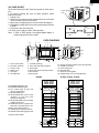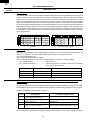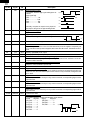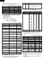
1
R-22GV
R-22GT
R-23GT
R-24GT
SERVICE MANUAL
S7508R24GT///
COMMERCIAL
MICROWAVE OVEN
MODELS
R-22GV
R-22GT
R-23GT
R-24GT
In the interest of user-safety the oven should be restored to its original
condition and only parts identical to those specified should be used.
R-24GT
TABLE OF CONTENTS
Page
PRECAUTIONS TO BE OBSERVED BEFORE AND DURING SERVICE TO
AVOID POSSIBLE EXPOSURE TO EXCESSIVE MICROWAVE ENERGY ................... INSIDE FRONT COVER
BEFORE SERVICING ........................................................................................................................................... 1
MICROWAVE MEASUREMENT PROCEDURE ................................................................................................... 2
FOREWORD .......................................................................................................................................................... 3
PRODUCT SPECIFICATIONS .............................................................................................................................. 4
GENERAL INFORMATION ................................................................................................................................... 4
OPERATION .......................................................................................................................................................... 6
TROUBLE SHOOTING GUIDE/ TEST PROCEDURE ........................................................................................ 11
TOUCH CONTROL PANEL ................................................................................................................................. 19
COMPONENT REPLACEMENT AND ADJUSTMENT PROCEDURE ................................................................ 28
PICTORIAL DIAGRAM ........................................................................................................................................ 33
CONTROL PANEL CIRCUIT ............................................................................................................................... 35
PRINTED WIRING BOARD ................................................................................................................................. 39
PARTS LIST ........................................................................................................................................................ 40
PACKING AND ACCESSORIES ......................................................................................................................... 46
SHARP ELECTRONICS CORPORATION
Service Headquarters:
Sharp Plaza,
Mahwah,
New Jersey
07430-2135
R-22GV
R-22GT
R-23GT
R-24GT
PRECAUTIONS TO BE OBSERVED BEFORE AND
DURING SERVICING TO AVOID POSSIBLE
EXPOSURE TO EXCESSIVE MICROWAVE
ENERGY
(a) Do not operate or allow the oven to be operated with the door open.
(b) Make the following safety checks on all ovens to be serviced before activating the magnetron or other
microwave source, and make repairs as necessary: (1) interlock operation (2) proper door closing, (3)
seal and sealing surfaces (arcing, wear, and other damage), (4) damage to or loosening of hinges and
latches, (5) evidence of dropping or abuse.
(c) Before turning on microwave power for any service test or inspection within the microwave generating
compartments, check the magnetron, wave guide or transmission line, and cavity for proper alignment,
integrity, and connections.
(d) Any defective or misadjusted components in the interlock, monitor, door seal, and microwave
generation and transmission systems shall be repaired, replaced, or adjusted by procedures described
in this manual before the oven is released to the owner.
(e) A microwave leakage check to verify compliance with the Federal Performance Standard should be
performed on each oven prior to release to the owner.
R-22GV
R-22GV
R-22GT
R-23GT
R-24GT
BEFORE SERVICING
Before servicing an operative unit, perform a microwave emission check as per the Microwave
Measurement Procedure outlined in this service manual.
If microwave emissions level is in excess of the specified limit, contact SHARP ELECTRONICS
CORPORATION immediately @1-800-237-4277.
If the unit operates with the door open, service person should 1) tell the user not to operate the oven
and 2) contact SHARP ELECTRONICS CORPORATION and Food and Drug Administration's
Center for Devices and Radiological Health immediately.
Service personnel should inform SHARP ELECTRONICS CORPORATION of any certified unit found
with emissions in excess of 4mW/cm2. The owner of the unit should be instructed not to use the unit
until the oven has been brought into compliance.
1
R-22GV
R-22GT
R-23GT
R-24GT
MICROWAVE MEASUREMENT PROCEDURE
A. Requirements:
1) Microwave leakage limit (Power density limit): The power density of microwave radiation emitted by a microwave oven
should not exceed 1mW/cm2 at any point 5cm or more from the external surface of the oven, measured prior to acquisition
by a purchaser, and thereafter (through the useful life of the oven), 5 mW/cm2 at any point 5cm or more from the external
surface of the oven.
2) Safety interlock switches: The primary interlock relay and door sensing switch shall prevent microwave radiation emission
in excess of the requirement as mentioned above, and secondary interlock switch shall prevent microwave radiation
emission in excess of 5 mW/cm2 at any point 5cm or more from the external surface of the oven.
B. Preparation for testing:
Before beginning the actual measurement of leakage, proceed as follows:
1) Make sure that the actual instrument is operating normally as specified in its instruction booklet.
Important:
Survey instruments that comply with the requirement for instrumentation as prescribed by the performance standard
for microwave ovens, 21 CFR 1030.10(c)(3)(i), must be used for testing.
2) Place the oven tray in the oven cavity.
3) Place the load of 275±15 ml (9.8 oz) of tap water initially at 20±5˚C (68˚F) in the center of the oven cavity.
The water container shall be a low form of 600 ml (20 oz) beaker with an inside diameter of approx. 8.5 cm (3-1/2 in.)
and made of an electrically nonconductive material such as glass or plastic.
The placing of this standard load in the oven is important not only to protect the oven, but also to insure that any leakage
is measured accurately.
4) Set the cooking control on Full Power Cooking Mode
5) Close the door and select a cook cycle of several minutes. If the water begins to boil before the survey is completed,
replace it with 275 ml of cool water.
C. Leakage test:
Closed-door leakage test (microwave measurement)
1) Grasp the probe of the survey instrument and hold it perpendicular to the gap between the door and the body of the oven.
2) Move the probe slowly, not faster than 1 in./sec. (2.5 cm/sec.) along the gap, watching for the maximum indication on
the meter.
3) Check for leakage at the door screen, sheet metal seams and other accessible positions where the continuity of the metal
has been breached (eg., around the switches, indicator, and vents).
While testing for leakage around the door pull the door away from the front of the oven as far as is permitted by the closed
latch assembly.
4) Measure carefully at the point of highest leakage and make sure that the highest leakage is no greater than 4mW/cm2,
and that the secondary interlock switch does turn the oven OFF before any door movement.
NOTE: After servicing, record data on service invoice and microwave leakage report.
2
R-22GV
R-22GT
R-23GT
R-24GT
SERVICE MANUAL
PRODUCT DESCRIPTION
COMMERCIAL
MICROWAVE OVEN
GENERAL INFORMATION
R-22GV/ R-22GT/ R-23GT/ R-24GT
FOREWORD
This Manual has been prepared to provide Sharp Electronics
Corp. Service Personnel with Operation and Service Information for the SHARP MICROWAVE OVENS, R-22GV, R-22GT,
R-23GT, R-24GT.
It is recommended that service personnel carefully study the
entire text of this manual so that they will be qualified to render
satisfactory customer service.
Check the interlock switches and the door seal carefully.
Special attention should be given to avoid electrical shock and
microwave radiation hazard.
OPERATION
TROUBLESHOOTING GUIDE
AND TEST PROCEDURE
TOUCH CONTROL PANEL
COMPONENT REPLACEMENT AND
ADJUSTMENT PROCEDURE
WIRING DIAGRAM
PARTS LIST
SHARP ELECTRONICS CORPORATION
SHARP PLAZA, MAHWAH,
NEW JERSEY 07430-2135
3
R-22GV
R-22GT
R-23GT
R-24GT
SPECIFICATION
ITEM
Power Requirements
Power Output
DESCRIPTION
120 Volts / 2.0 KW (R-22GV, R-22GT)
Approx. 17.7A
230/208 Volts / 2.5 kW (R-23GT)
Approx. 13A at 208V, 11.9A at 230V
230/208 Volts / 2.9 kW (R-24GT)
Approx. 14 A at 208V, 13.2A at 230V
60 Hertz / Single phase, 3 wire grounded
1200 W (R-22GV, R-22GT)/ 1600 W (R-23GT)/ 1800 W (R-24GT)
(IEC-705 TEST PROCEDURE) Operating frequency of 2450MHz
Case Dimensions
Cooking Cavity Dimensions
Width 20-1/8"
Width 13"
Control Complement
Touch Control System
Digital Display
10 Number Pads
STOP/CLEAR pad
START pad
SELECTAPOWER pad (Power level: 0 to 100%; except R-22GV)
SELECTATIME pad
DOUBLE QUANTITY pad
EXPRESS DEFROST pad
Memory SET pad
Memory CHECK pad
SIGNAL pad
Weight
Approx. 57 lbs/ 26 kg (R-22GV, R-22GT)/ Approx. 63 lbs/ 29 kg (R-23GT)
Approx. 66 lbs/ 30 kg (R-24GT)
UL Listed
FCC Authorized
DHHS Rules, CFR, Title 21, Chapter 1, Subchapter J
NSF Certified
Safety Standard
Height 13-1/4"
Height 7-1/8"
Depth 18-1/2"
Depth 13"
GENERAL INFORMATION
GROUNDING INSTRUCTIONS
This appliance must be grounded. In the event of an electrical short circuit, grounding reduces the risk of electric shock by
providing an escape wire for the electric current. This appliance is equipped with a cord having a grounding wire with a
grounding plug. The plug must be plugged into an outlet that is properly installed and grounded.
WARNING: Improper use of the grounding plug can result in a risk of electric shock. The electrical requirements are 120
Volt, 60 Hz AC only, 20 Amp or more (R-22GV,R-22GT); 230/208 Volt, 60 Hz, AC only, 15 Amp or more (R23GT) and 20 Amp or more (R-24GT) fused electrical supply. It is recommended that a separate circuit serving
only this appliance be provided. When installing this appliance, observe all applicable codes and ordinances.
If it is necessary to use an extension cord, use only a 3-wire extension cord that has a 3-blade grounding plug
and a 3-slot receptacle that will accept the plug on the appliance. The marked rating of the extension cord should
be AC 120 Volt 20 Amp (R-22GV,R-22GT), AC 230/208 Volt 15 Amp (R-23GT), AC230/208 Volt 20 Amp (R24GT).
Receptacle Box Cover
Receptacle Box Cover
Receptacle Box Cover
3-Pronged plug
(5-20P)
3-Pronged plug
(6-15P)
3-Pronged plug
(6-15P)
3-Pronged, Receptacle
(5-20R)
3-Pronged, Receptacle
(6-15R)
3-Pronged, Receptacle
(6-20R)
120V 20A
R-22GV, R-22GT
230/208V15A
R-23GT
230/208V20A
R-24GT
4
R-22GV
R-22GT
R-23GT
R-24GT
VOLTAGE SELECT
The R-23GT and the R-24GT have been preset for 230V operation.
If you need to change this oven for 208V operation, follow
instructions below.
1. Unplug oven.
2. Remove one screw(A) from the Voltage Select Cover located
on back of the oven near the bottom.
3. Remove the Voltage Select Cover and rotate 180 degrees.
4. Reinstall the Voltage Select Cover using one screw(A) removed
in Step 2.
5. Plug power cord into wall outlet.
Your oven is now ready for 208V, 60Hz operation.
Note: If “EE4” or “EE5” appear in the lighted digital display, a
voltage adjustment must be made.
Power supply
cord
208 V
230 V (A)
230 V
208 V
OVEN DIAGRAM
10
9
5
4
3
2
16
17
1
13
14
12
18
15
11
1.
2.
3.
4.
5.
6.
Touch control panel
Door latch openings
Ceramic shelf
Splash cover
Oven light
Air intake filter
8
7
6
7. Air intake openings
8. Door seals and sealing surfaces
9. Door hinges
10. Oven door with see-through window
11. Door latches
12. Door handle
13. Service window for replacing the oven light bulb.
14. Ventilation openings
15. Power supply cord
16. Mounting plate
17. Screw for mouning plate
18. Voltage select cover (R-23GT/R-24GT)
R-22GV
R-22GT, R-23GT, R-24GT
ON DEF NO. X2 CHECK
19. DOUBLE QUANTITY pad
20. EXPRESS DEFROST pad
21. Ten number pads for time and
memory programming
22. SELECTATIME pad
23. STOP/CLEAR pad; touch to stop
operation of oven and clear
remaining heating time
24. SELECTAPOWER pad for setting
variable power level
25. START pad; touch to operate oven
after door is closed and time is set
26. SET pad for setting memory
27. CHECK pad for checking memory
28. SIGNAL pad for setting signal sound
19
DOUBLE
QUANTITY
EXPRESS
DEFROST
ON DEF NO. X2 CHECK
20
19
DOUBLE
QUANTITY
EXPRESS
DEFROST
1
11
1
2
12
2
3
13
3
4
14
4
15
5
16
6
17
7
18
8
19
9
20
0
5
21
6
7
8
9
Accessory: Menu labels
0
20
21
23
22
SELECTATIME
STOP/CLEAR
23
22
SELECTA
TIME
STOP
CLEAR
START
25
24
SELECTAPOWER
START
25
26
SET
CHECK
SIGNAL
28
26
SET
CHECK
27
27
5
SIGNAL
28
R-22GV
R-22GT
R-23GT
R-24GT
OPERATION
DESCRIPTION OF OPERATING SEQUENCE
circuits to the high voltage components are de-energized,
and the digital read-out displays " . " and cooking is
cancelled (in the case of Memory cooking).
7. The monitor switch (1) is electrically monitoring the
operation of the secondary interlock switch (1) and
primary interlock relay (1), and monitor switch (2) is
electrically monitoring the operation of the secondary
interlock switch (2) and primary interlock relay (2), and
monitor switches (1), (2) are mechanically associated
with the door so that it will function in the following
sequence.
(1) When the door opens from a closed position, the contacts
of the primary interlock relays (1), (2) and secondary
interlock switches (1), (2) open. Then the monitor switch
contacts close.
(2) When the door is closed from the open position, the
monitor switches (1), (2) contacts first open, and then the
contacts of the secondary interlock switches (1), (2)
close.
The following is a description of component functions during
oven operation.
OFF CONDITION
Closing the door activates the door sensing switch and
secondary interlock switches (1), (2). (In this condition, the
monitor switches (1) & (2) contacts are opened.) When the
oven is plugged in, and the rated voltage is supplied to the
control unit, (figure O-1), the display will show " . ".
IDLE CONDITION
When the door is opened, the contacts of the door sensing
switch open, initiating the following:
1. A signal is input to the control unit energizing the coil of
shut-off relay (RY-1).
2. The shut-off relay (RY-1) contacts close completing
circuits to turn on the oven lamp, blower motor and stirrer
motors.
3. If the door remains open, 60 seconds later the control
unit de-energizes shut-off relay (RY-1) turning off the
oven lamp, blower motor and stirrer motors.
When the door is closed, the door sensing switch contacts
close. With the closing of the door sensing switch contacts,
an additional circuit is provided which will permit the operation of the oven when one of the touch pads is depressed.
Since the control is enabled through the door sensing
switch, the door must be closed before the touch pads will
be effective. When the door is closed, a full 60 second IDLE
condition is always provided for selecting and pressing the
desired touch pads. A 60 second IDLE condition will also
follow the end of each cook cycle.
If the secondary interlock switches (1), (2) and primary interlock
relays (1), (2) fail with their contacts closed when the door is
opened, the closing of the monitor switches (1), (2) contacts will
form a short circuit through the monitor fuse, secondary interlock switches (1), (2) and primary interlock relays (1), (2),
causing the monitor fuse to blow.
VARIABLE POWER COOKING
( EXCEPT R-22GV)
When Variable Cooking Power is programmed, the rated
voltage A.C. is supplied to the power transformer intermittently
through the contacts of relay (RY-2, RY-3). Relays RY-2 and
RY-3 are operated by the control unit within an interval second
time base. Microwave power operation is as follows:
COOKING CONDITION
When the door is closed from the open position and Memory
pad is touched the, following will occur:
POWER LEVEL
100%
90%
80 %
70%
60%
50%
40%
30%
20%
10%
0%
1. The contacts of relays are closed and components
connected to the relays are turned on (For details, refer
to Figure O-3)
2. Rated voltage is supplied to the primary winding of the
power transformer and is converted to about 3.3 volts
(for R-22GV, R-22GT) / 3.1 volts (for R-23GT, R-24GT)
output on the filament winding, and approximately 2000
volts (for R-22GV, R-22GT) / 2040 volts (for R-23GT, R24GT) on the high voltage winding.
3. The filament winding voltage heats the magnetron
filament and the H.V. winding voltage is sent to a voltage
doubler circuit.
4. The microwave energy produced by the magnetron is
channelled through the waveguide into the cavity feedbox, and then into the cavity where the food is placed to
be cooked.
5. Upon completion of the cooking time, the oven will revert
to the IDLE condition.
6. When the door is opened during a cook cycle, monitor
switches (1) & (2), door sensing switch, secondary
interlock switches (1), (2) and primary interlock relays
(1), (2) are activated with the following results. The
6
ON TIME
32 sec.
30 sec.
26 sec.
24 sec.
22 sec.
18 sec.
16 sec.
12 sec.
8 sec.
6 sec.
0 sec.
OFF TIME
0 sec.
2 sec.
6 sec.
8 sec.
10 sec.
14 sec.
16 sec.
20 sec.
24 sec.
26 sec.
32 sec.
Note:
The ON/OFF time ratio does not exactly correspond
with the percentage of microwave power, because
approx. 2 seconds are needed for heating of the
magnetron filament.
Note:
R-22GV has only 100% power level.
R-22GV
R-22GT
R-23GT
R-24GT
TWO MAGNETRON OPERATION SYSTEM
OPERATION OF
MAGNETRON
Two magnetrons (1), (2) are equipped in order to get higher
microwave power output. The primary windings of the
power transformers (1), (2) are connected so that each
magnetron can be oscillated alternatively according to the
frequency of the power supply. Refer to the Figure B-1.
COMMERCIAL
FREQUENCY
(60HZ)
POWER OUTPUT
BY MAGNETRON 1
POWER OUTPUT
BY MAGNETRON 2
SCHEMATIC
Figure B-1. Operation of Magnetron
NOTE: CONDITION OF OVEN
1. DOOR CLOSED OR 1 MINUTE AFTER COOK OFF
2. " . " APPEARS ON DISPLAY
FUSE 20A
SECONDARY
INTERLOCK
SWITCH (1)
PRIMARY
INTERLOCK
RELAY (1)
SECONDARY
INTERLOCK
SWITCH (2)
PRIMARY
INTERLOCK
RELAY (2)
MAGNETRON
THERMAL
CUT-OUT (1)
(UPPER)
YLW
MAGNETRON (1)
(UPPER)
RECTIFIER (1)
MAGNETRON (2)
(LOWER)
RECTIFIER (2)
BLK
MONITOR SWITCH (2)
CAPACITOR (2)
0.75µF
WHT/GRY
D3 D1
TAB1
TAB2
OVEN LAMP
OL
SM
STIRRER MOTOR
STIRRER MOTOR
SM
BLOWER MOTOR
DOOR SENSING
SWITCH
GRY
GRY
B1
POWER
TRANSFORMER (2)
(REAR)
INTAKE
THERMISTOR
B2
MONITOR SWITCH (1)
MAGNETRON
THERMISTOR
OVEN
THERMISTOR
B3
H3 H1
RY3
RY2
RY1
A3
BLK
YLW
BLOWER
MOTOR
THERMAL
CUT-OUT
OVEN
THERMAL
CUT-OUT
BLK
120V 60Hz
A1
MAGNETRON
THERMAL
CUT-OUT (2)
(LOWER)
CAPACITOR (1)
0.75µF
GRN
BM
POWER
TRANSFORMER (1)
(FRONT)
BLK
A7
WHT
ORG
GRY
Figure O-1. R-22GV/GT Oven SChematic-OFF Condition
MAGNETRON
THERMAL
CUT-OUT (1)
(UPPER)
PRIMARY
INTERLOCK
RELAY (1)
BLK
RED
COM
SECONDARY
INTERLOCK
SWITCH (2)
Figure O-1. R-23GT/24GT Oven SChematic-OFF Condition (208 VCondition)
MAGNETRON (2)
(LOWER)
CAPACITOR (2)
0.94µF
RECTIFIER (2)
NC
COM
7
MAGNETRON (1)
(UPPER)
CAPACITOR (1)
0.94µF
RECTIFIER (1)
V.S.SW (3)
RED
MONITOR SWITCH (1)
MONITOR SWITCH (2)
OVEN
THERMISTOR
SECONDARY
INTERLOCK
SWITCH (1)
NC
COM
POWER
TRANSFORMER (2)
(REAR)
V.S.SW (4)
D3 D1
TAB1
TAB2
OVEN LAMP
OL
OL
DOOR SENSING
SWITCH
SM
COM
STIRRER MOTOR
NC
B1
INTAKE
THERMISTOR
B3
H3
H1
RY3
RY2
RY1
BLOWER
MOTOR
B2
SM
V.S.SW
(1)
BM
VOLTAGE SELECT
SWITCH (V.S.SW) (2)
WHT/GRY
WHT
NC
A3
MAGNETRON
THERMISTOR
PNK
BLOWER
MOTOR
THERMAL
CUT-OUT
BLK
208/230V 60Hz
A5
WHT
OVEN
THERMAL
CUT-OUT
MAGNETRON
THERMAL
CUT-OUT (2)
(LOWER)
A7
A1
POWER
TRANSFORMER (1)
(FRONT)
RED
PNK
PRIMARY
INTERLOCK
RELAY (2)
GRY
FUSE 20A
R-22GV
R-22GT
R-23GT
R-24GT
SCHEMATIC
NOTE: CONDITION OF OVEN
1. FOR 1MINUTE AFTER DOOR OPENED.
2. " . " APPEARS ON DISPLAY.
SECONDARY
INTERLOCK
SWITCH (1)
FUSE 20A
MAGNETRON
THERMAL
CUT-OUT (1)
(UPPER)
PRIMARY
INTERLOCK
RELAY (1)
YLW
A3
B2
B1
MAGNETRON (1)
(UPPER)
RECTIFIER (1)
BLK
POWER
TRANSFORMER (2)
(REAR)
BLK
MAGNETRON
THERMISTOR
MONITOR SWITCH (2)
B3
H3 H1
RY3
RY2
RY1
120V 60Hz
GRN
A1
MAGNETRON
THERMAL
CUT-OUT (2)
(LOWER)
CAPACITOR (1)
0.75µF
OVEN
THERMISTOR
BLK
BLOWER
MOTOR
THERMAL
CUT-OUT
YLW
PRIMARY
INTERLOCK
RELAY (2)
MONITOR SWITCH (1)
OVEN
THERMAL
CUT-OUT
BLK
SECONDARY
INTERLOCK
SWITCH (2)
A7
WHT
POWER
TRANSFORMER (1)
(FRONT)
ORG
GRY
MAGNETRON (2)
(LOWER)
RECTIFIER (2)
CAPACITOR (2)
0.75µF
WHT/GRY
D3 D1
TAB1
TAB2
OVEN LAMP
OL
SM
STIRRER MOTOR
STIRRER MOTOR
SM
BM
BLOWER MOTOR
DOOR SENSING
SWITCH
INTAKE
THERMISTOR
GRY
GRY
Figure O-2. R-22GV/22GT Oven SChematic-IDLE Condition
MAGNETRON
THERMAL
CUT-OUT (1)
(UPPER)
PRIMARY
INTERLOCK
RELAY (1)
BLK
RED
COM
CAPACITOR (2)
0.94µF
SECONDARY
INTERLOCK
SWITCH (2)
Figure O-2. R-23GT/24GT Oven SChematic-IDLE Condition (208 VCondition)
MAGNETRON (2)
(LOWER)
NC
COM
8
MAGNETRON (1)
(UPPER)
RECTIFIER (1)
V.S.SW (3)
RED
MONITOR SWITCH (1)
MONITOR SWITCH (2)
CAPACITOR (1)
0.94µF
COM
RECTIFIER (2)
SECONDARY
INTERLOCK
SWITCH (1)
NC
POWER
TRANSFORMER (2)
(REAR)
V.S.SW (4)
D3 D1
TAB1
TAB2
OVEN LAMP
OL
OL
DOOR SENSING
SWITCH
SM
COM
STIRRER MOTOR
NC
OVEN
THERMISTOR
B1
INTAKE
THERMISTOR
B3
H3
H1
RY3
RY2
RY1
BLOWER
MOTOR
B2
SM
V.S.SW
(1)
BM
VOLTAGE SELECT
SWITCH (V.S.SW) (2)
WHT/GRY
WHT
NC
A3
MAGNETRON
THERMISTOR
PNK
BLOWER
MOTOR
THERMAL
CUT-OUT
BLK
208/230V 60Hz
A5
WHT
OVEN
THERMAL
CUT-OUT
MAGNETRON
THERMAL
CUT-OUT (2)
(LOWER)
PRIMARY
INTERLOCK
RELAY (2)
A7
A1
POWER
TRANSFORMER (1)
(FRONT)
RED
PNK
GRY
FUSE 20A
R-22GV
R-22GT
R-23GT
R-24GT
SCHEMATIC
NOTE: CONDITION OF OVEN
DOOR CLOSED.
SELECTATIME PAD TOUCHED.
COOKING TIME PROGRAMMED.
START PAD TOUCHED.
FUSE 20A
SECONDARY
INTERLOCK
SWITCH (1)
PRIMARY
INTERLOCK
RELAY (1)
SECONDARY
INTERLOCK
SWITCH (2)
PRIMARY
INTERLOCK
RELAY (2)
MAGNETRON
THERMAL
CUT-OUT (1)
(UPPER)
YLW
BLK
MAGNETRON (1)
(UPPER)
RECTIFIER (1)
MONITOR SWITCH (2)
MONITOR SWITCH (1)
MAGNETRON
THERMISTOR
CAPACITOR (2)
0.75µF
WHT/GRY
D3 D1
TAB1
TAB2
OVEN LAMP
OL
SM
STIRRER MOTOR
STIRRER MOTOR
SM
BM
BLOWER MOTOR
DOOR SENSING
SWITCH
MAGNETRON (2)
(LOWER)
GRY
B1
RECTIFIER (2)
B2
POWER
TRANSFORMER (2)
(REAR)
GRY
A3
BLK
YLW
B3
H3 H1
RY3
RY2
RY1
120V 60Hz
GRN
A1
MAGNETRON
THERMAL
CUT-OUT (2)
(LOWER)
CAPACITOR (1)
0.75µF
OVEN
THERMISTOR
BLK
BLOWER
MOTOR
THERMAL
CUT-OUT
OVEN
THERMAL
CUT-OUT
BLK
A7
WHT
POWER
TRANSFORMER (1)
(FRONT)
ORG
INTAKE
THERMISTOR
1.
2.
3.
4.
GRY
Figure O-3. R-22GV/22GT Oven SChematic-Cooking Condition
MAGNETRON
THERMAL
CUT-OUT (1)
(UPPER)
PRIMARY
INTERLOCK
RELAY (1)
BLK
RED
COM
CAPACITOR (2)
0.94µF
SECONDARY
INTERLOCK
SWITCH (2)
Figure O-3. R-23GT/24GT Oven SChematic-Cooking Condition (208 VCondition)
MAGNETRON (2)
(LOWER)
NC
COM
9
MAGNETRON (1)
(UPPER)
RECTIFIER (1)
V.S.SW (3)
RED
MONITOR SWITCH (1)
MONITOR SWITCH (2)
CAPACITOR (1)
0.94µF
COM
RECTIFIER (2)
SECONDARY
INTERLOCK
SWITCH (1)
NC
POWER
TRANSFORMER (2)
(REAR)
V.S.SW (4)
D3 D1
TAB1
TAB2
OVEN LAMP
OL
OL
DOOR SENSING
SWITCH
SM
COM
STIRRER MOTOR
NC
OVEN
THERMISTOR
B1
SM
BLOWER
MOTOR
B2
INTAKE
THERMISTOR
B3
H3
H1
RY3
RY2
RY1
V.S.SW
(1)
BM
VOLTAGE SELECT
SWITCH (V.S.SW) (2)
WHT/GRY
WHT
NC
A3
MAGNETRON
THERMISTOR
PNK
BLOWER
MOTOR
THERMAL
CUT-OUT
BLK
208/230V 60Hz
A5
WHT
OVEN
THERMAL
CUT-OUT
MAGNETRON
THERMAL
CUT-OUT (2)
(LOWER)
PRIMARY
INTERLOCK
RELAY (2)
A7
A1
POWER
TRANSFORMER (1)
(FRONT)
RED
PNK
GRY
FUSE 20A
R-22GV
R-22GT
R-23GT
R-24GT
DESCRIPTION AND FUNCTION OF COMPONENTS
Functions:
With the door shut, the contacts of the door sensing switch
and the secondary interlock switches (1), (2) are closed and
the contacts of the monitor switches (1), (2) are open.
1. When the door is opened, the contact of the door sensing
switch and secondary interlock switches (1), (2) are
opened first, then the contact of the monitor switches (1),
(2) are closed.
2. As the door goes to a closed position, the contacts of the
monitor switches (1), (2) are opened first, then the
contacts of the door sensing switch and the secondary
interlock switches (1), (2) close.
3. If the door is opened, and the contacts of the primary
interlock relay and secondary interlock switch of the
same circuit fail to open, the monitor fuse blows
simultaneously with closing of the monitor switch contacts
of that circuit (1 or 2).
CAUTION: BEFORE REPLACING A BLOWN MONITOR
FUSE TEST THE DOOR SENSING SWITCH,
PRIMARY INTERLOCK RELAYS (1), (2), SECONDARY INTERLOCK SWITCHES (1), (2) AND
MONITOR SWITCHES (1), (2) FOR PROPER
OPERATION. (REFER TO CHAPTER "TEST
PROCEDURE").
NOTE: MONITOR FUSE AND SWITCH ARE REPLACED
AS AN ASSEMBLY.
DOOR OPEN MECHANISM
1. The door release lever is pulled.
2. The upper latch head is lifted up by the linked door
release lever.
3. The latch lever is lifted up by the door release lever.
4. The joint lever is lifted up by the latch lever.
5. The lower latch head is lifted up by the joint lever.
6. Now both latch heads are lifted up, so they can be
released from the latch hook.
7. Now the door can be opened.
Door release
lever
Latch head
Switch lever A
Monitor switch (2)
Monitor switch (1)
Latch hook
Switch lever B
Secondary interlock
switch (1)
Joint lever
Latch lever
Secondary interlock
switch (2)
Door sensing switch
Switch lever C
Latch head
Figure D-1. Door Open Mechanism
MAGNETRON THERMAL CUT-OUTS (1), (2)
The thermal cut-outs (1), (2) located on the top of the upper
and lower waveguide, are designed to prevent damage to
the magnetrons (1), (2). If an over heated condition develops in the tube due to blower motor failure, obstructed air
ducts, dirty or blocked air intake, etc., the circuit to the
magnetrons are interrupted. Under normal operation, the
thermal cut-outs remains closed. However, when abnormally high temperatures are generated within the magnetron,
the thermal cut-out will open at 293˚F (145˚C) causing the
microwave energy to stop. The defective thermal cut-out
must be replaced with new rated one.
DOOR SENSING SWITCH
The door sensing switch is activated by the latch head of the
door and switch lever C. When the door is opened, the
contacts of the switch open and interrupt the circuit to the
coils of the primary interlock relay (1), (2). The contacts of
the primary relay (1), (2) then open and interrupt the circuit
to the primary winding of the power transformers. At this
time, the contacts of relay RY1 close and the blower motor,
stirrer motors and oven lamps are energized for 1 minute.
SECONDARY INTERLOCK SWITCHES (1), (2)
The secondary interlock switch (1), (2) are activated by the
upper latch head of the door and switch lever B. When the
door is opened, the contacts of the switch open and interrupt
the circuit to the primary winding of the power transformers
(1), (2).
OVEN THERMAL CUT-OUT
The thermal cut-out, located on the side of the exhaust duct
assembly, is designed to prevent damage to the oven by
fire. If the food load is overcooked, by either error in cook
time or defect in the control unit, the thermal cut-out will
open. Under normal operation, the oven thermal cut-out
remains closed. However, when abnormally high temperatures are generated within the oven cavity, the oven thermal
cut-out will open at 239˚F (115˚C), causing the oven to shut
down. The defective thermal cut-out must be replaced with
new rated one.
MONITOR SWITCHES (1), (2)
The monitor switches (1), (2) are mounted in the upper
position of the latch hook. The monitor switches are activated by the upper latch head of the door and switch lever
A. When the door is opened, the contacts of the monitor
switches close. Monitor switch (1) is intended to render the
oven inoperative by means of blowing the monitor fuse,
when the contacts of the primary interlock relay (1) and
secondary interlock switch (1) fail to open when the door is
opened. Monitor switch (2) is intended to render the oven
inoperative by means of blowing the monitor fuse, when the
contacts of the primary interlock relay (2) and secondary
interlock switch (2) fail to open when the door is opened.
OVEN THERMISTOR
The thermistor is a negative temperature coefficient type.
The temperature in the exhaust duct is detected through the
resistance of the thermistor.
If the temperature is high, the control panel will display “EE7”
and the oven will stop to avoid overheating and catching fire.
If the thermistor is open, the control panel will display "EE6"
and the oven will stop.
10
R-22GV
R-22GT
R-23GT
R-24GT
INTAKE THERMISTOR
OVEN LAMPS
This thermistor detects ambient air temperature. The thermistor is a negative temperature coefficient type. The temperature around the lower position of control panel is detected through the resistance of the thermistor.
If the thermistor remains in a shorted condition for more than
2 minutes, the control will display “EE10” and stop operating.
The oven cavity light illuminates the interior of the oven so
that food being cooked can be examined visually through
the door window without having to open the door. The oven
lamp is on during the cooking cycle and idle condition.
SELECT SWITCHES (1) - (4) (for R-23GT and R24GT)
The select switch assembly is an array of four separate
switches which may be configured for either 208V or 230V
operation (see General Information section, voltage select).
These switches are connected to the windings of components specified in the table below and make those components compatible with the specified line voltage by changing
their internal windings. For 208V operation contacts (Normal Open) of the all switches are open.
MAGNETRON THERMISTOR
The thermistor is a negative temperature coefficient type.
The air temperature around the lower magnetron is detected through the resistance of the thermistor.
If the temperature is high, the control panel will display
"EE17" and the oven will stop to protect the lower magnetron
against overheat.
If the thermistor is open, the control panel will display "EE16"
and the oven will stop.
SELECT SWITCH (1)
BLOWER MOTOR THERMAL CUT-OUT 115˚C
Oven
cavity
Rear
cabinet
side
This thermal cut-out protects the blower motor against
overheating. If its temperature goes above 239˚F (115˚C)
because the blower motor is stalled or the ventilation openings are blocked, the contacts of the thermal cut-out will
open. The line voltage to the control unit will be cut off and
the operation of the oven will be stopped. The defective
thermal cut-out must be replaced with a new one.
N.C.
COM.
SELECT
SWITCH (2)
N.O
SELECT SWITCH (4)
SCREW
SELECT SWITCH (3)
SELECT SWITCH ANGLE
SELECT SWITCH AND ELECTRICAL COMPONENTS
CONDITION
BLOWER MOTOR
SWITCH NO.
ELECTRICAL PARTS
The blower motor drives a blade which draws external cool
air into the oven. This cool air is directed through the air
vanes surrounding the magnetrons and cools the
magnetrons. This air is channelled through the oven cavity
to remove steam and vapours given off from the heating
foods. It is then exhausted through the exhausting air vents
at the oven cavity.
(1)
(2)
(3)
(4)
Touch control unit
Blower motor
Power transformer (1) (Front side)
Power transformer (2) (Rear side)
Oven in the 208V setting: contacts between common and
normally open are closed.
Oven in the 230V setting: contacts between common and
normally closed are closed.
STIRRER MOTOR
The upper and lower stirrer motors drive stirrer antennas to
stir the microwave radiation from the upper and lower
waveguides.
TROUBLESHOOTING GUIDE
When troubleshooting the microwave oven, it is helpful to follow the Sequence of Operation in performing the checks. Many of the
possible causes of trouble will require that a specific test be performed. These tests are given a procedure letter which will be found
in the "Test Procedure"section.
IMPORTANT: If the oven becomes inoperative because of a blown monitor fuse, check the monitor switches (1), (2),
primary interlock relays (1), (2), door sensing switch and secondary interlock switches (1), (2) before
replacing the monitor fuse. If monitor fuse is replaced, the mintor switches (1) and/or (2) must also be
replaced. Use part FFS-MA012WRK0 (R-22GV/22GT)/ FFS-MA015WRK0 (R-23GV/24GT) as an assembly.
11
R-22GV
R-22GT
R-23GT
R-24GT
CK = Check / RE = Replace/ RST= Reset
TEST PROCEDURE
CONDITION
A
B C D
E
F
F
G
I
J
PROBLEM
Home fuse blows when power cord is plugged
into wall receptacle
Monitor fuse blows when power cord is
plugged into wall receptacle.
OFF
CONDITION
" . " does not appear in display when power
cord is first plugged into wall receptacle.
Blower motor does not operate. (Oven lamp(s)
and stirrer motors go on for 1 minute after
door is opened.)
Blower motor, oven lamp(s) and stirrer motors do not go on for 1 minute after door is
opened.
Blower motor and stirrer motors go on but
oven lamp(s) do not light for 1 minute after
door is opened.
Blower motor, oven lamp(s) and stirrer motors keep going on after more than 1 minute
when door is opened and closed.
Blower motor, oven lamp(s) and stirrer motors do not go on in cook cycle.
Oven goes into a cook cycle but shuts down
before and off cooking cycle.
COOKING
CONDITION
Oven does not go into cook cycle when
START pad is touched.
Low or no power is produced during cooking
condition. (The food is heated incompletely
or not heated at all.)
Extremely uneven heating is produced in
oven load (food).
Variable cooking does not operates properly, except HIGH power functions.
"EE1" Magnetron (1) failure.
(1) (1) (1) (1)
(1)
(1)
"EE2" Magnetron (2) failure.
(2) (2) (2) (2)
(2)
(2)
"EE3" Magnetron (1) and (2) failure.
"EE4" Voltage is too high (for R-23GT/24GT).
"EE5" Voltage is too low (for R-23GT/24GT).
"EE6" Thermistor failure.
ERROR
MODE
"EE7" Exhaust air temperature is too high.
"EE8" Relay melt short.
"EE9" Maximum time is exceeded.
"EE0" Fan lock judge.
"EE10" Intake thermistor is shorted.
"EE16" Magnetron thermistor is open.
"EE17" Magnetron temperature is too high.
12
J CK CK H H
H H
R-22GV
R-22GT
R-23GT
R-24GT
J
K
K
K
L
M
N
N
N
O CK CK CK CK CK RST RST CK CK
13
R-22GV
R-22GT
R-23GT
R-24GT
TEST PROCEDURES
PROCEDURE
LETTER
A
COMPONENT TEST
MAGNETRON ASSEMBLY TEST
HIGH VOLTAGES ARE PRESENT DURING THE COOK CYCLE, SO EXTREME CAUTION SHOULD
BE OBSERVED.
DISCHARGE THE HIGH VOLTAGE CAPACITOR BEFORE TOUCHING ANY OVEN COMPONENTS
OR WIRING.
To test for an open filament, isolate the magnetron from the high voltage circuit. A continuity check across
the magnetron filament leads should indicate less than 1 ohm.
To test for a shorted magnetron, connect the ohmmeter leads between the magnetron filament leads and
chassis ground. This test should indicate an infinite resistance. If there is little or no resistance the
magnetron is grounded and must be replaced.
Power output of the magnetron can be measured by performing a water temperature rise test. This test
should only be used if above tests do not indicate a faulty magnetron and there is no defect in the following
components or wiring: silicon rectifier, high voltage capacitor and power transformer. This test will require
a 16 ounce (453cc) measuring cup and an accurate mercury thermometer or thermocouple type
temperature tester. For accurate results, the following procedure must be followed carefully:
1. Fill the measuring cup with 16 oz. (453cc) of tap water and measure the temperature of the water with
a thermometer or thermocouple temperature tester. Stir the thermometer or thermocouple through
the water until the temperature stabilizes. Record the temperature of the water.
2. Place the cup of water in the oven. Operate oven at 100 % POWER selecting more than 60 seconds
cook time. Allow the water to heat for 60 seconds, measuring with a stop watch, second hand of a
watch or the digital read-out countdown.
3. Remove the cup from the oven and again measure the temperature, making sure to stir the
thermometer or thermocouple through the water until the maximum temperature is recorded.
4. Subtract the cold water temperature from the hot water temperature. Refer to the chart below for the
normal temperature rise of each model. If the water temperatures are accurately measured and
tested for the required time period the test results will indicate if the magnetron tube has low power
output (low rise in water temperature) which would extend cooking time or high power output (high
rise in water temperature) which would reduce cooking time. Because cooking time can be adjusted
to compensate for power output, the magnetron tube assembly should be replaced only if the water
temperature rise test indicates a power output well beyond the normal limits. The test is only accurate
if the power supply line voltage is 208/230 volts for models R-23GT, R24GT and 120 volts for models
R-22GV, R-22GT and the oven cavity is clean.
B
Model
RF output
Normal temperature rise
Line voltage
R-22GV/22GT
1200W
36.5 - 67.9˚F (20.3 - 37.7˚C)
120V
R-23GT
1600W
46.6 - 86.6˚F (25.9 - 48.1˚C)
208V/230V
R-24GT
1800W
50.4 - 93.6˚F (28.0 - 52.0˚C)
208V/230V
POWER TRANSFORMER TEST
DISCHARGE THE HIGH VOLTAGE CAPACITOR BEFORE TOUCHING ANY OVEN COMPONENTS
OR WIRING.
Disconnect the primary input terminals and the secondary output terminals, and measure the resistance
of the transformer with an ohmmeter. Check for continuity of the coils with an ohmmeter. On the R x 1
scale, the resistance of the filament coil should be approximately and the resistance of the high voltage
coil and primary coil should be as follows:
Model
R-22GV/22GT
R-23GT
R-24GT
Primary coil
Approx. 0.42 Ω
Approx. 0.86 Ω (at 208V)
Approx. 0.95 Ω (at 230V)
Approx. 0.86 Ω (at 208V)
Approx. 0.95 Ω (at 230V)
14
High voltage coil
Approx. 106 Ω
Approx. 65 Ω
Part code
RTRN-A453WRE0
RTRN-A454WRE0
Approx. 60 Ω
RTRN-A455WRE0
R-22GV
R-22GT
R-23GT
R-24GT
TEST PROCEDURES (CONT'D)
PROCEDURE
LETTER
COMPONENT TEST
(HIGH VOLTAGES ARE PRESENT AT THE HIGH VOLTAGE TERMINAL, SO DO NOT ATTEMPT TO
MEASURE THE VOLTAGE OF THE FILAMENT AND HIGH VOLTAGE COILS.)
C
HIGH VOLTAGE RECTIFIER (1) AND/OR (2) TEST
DISCHARGE THE HIGH VOLTAGE CAPACITOR BEFORE TOUCHING ANY OVEN COMPONENTS
OR WIRING.
Isolate the rectifier from the circuit. Using the highest ohm scale of the meter, read the resistance across
the terminals and observe, reverse the leads to the rectifier terminals and observe meter reading. If a
short is indicated in both directions, or if an infinite resistance is read in both directions, the rectifier is
probably defective and should be replaced.
NOTE: Be sure to use an ohm-meter that will supply a forward bias voltage of more than 6.3 volts.
D
HIGH VOLTAGE CAPACITOR (1) AND/OR (2) TEST
DISCHARGE THE HIGH VOLTAGE CAPACITOR BEFORE TOUCHING ANY OVEN COMPONENTS
OR WIRING.
If the capacitor is open, no high voltage will be available to the magnetron. Disconnect input leads and
check for short or open between the terminals using an ohmmeter.
Checking with a high ohm scale, if the high voltage capacitor is normal, the meter will indicate continuity
for a short time and should indicate an open circuit once the capacitor is charged. If the above is not the
case, check the capacitor with an ohmmeter to see if it is shorted between either of the terminals and
case. If it is shorted, replace the capacitor.
E
SECONDARY INTERLOCK SWITCH TEST
Isolate the switch and connect the ohmmeter to the common (COM.) and normally open (NO) terminal
of the switch. The meter should indicated an open circuit with the door open and a closed circuit with the
door closed. If improper operation is indicated, replace the secondary interlock switch.
F
PRIMARY INTERLOCK SYSTEM TEST
DOOR SENSING SWITCH
Isolate the switch and connect the ohmmeter to the common (COM.) and normally open (NO) terminal
of the switch. The meter should indicated an open circuit with the door open and a closed circuit with the
door closed. If improper operation is indicated, replace the door sensing switch.
NOTE: If the door sensing switch contacts fail in the open position and the door is closed, the blower
motor, stirrer motors and oven light will be activated by RY1 for one minute.
PRIMARY INTERLOCK RELAY (1), (2)
Disconnect two (2) wire leads from the male tab terminal of the Primary Interlock Relay (1) and (2).
Primary Interlock Relay (1)
RY-2
Primary Interlock Relay (2)
RY-3
Check the state of the relay contacts via tab terminal using a ohmmeter. The relay contacts should be
open. If the relay contacts are closed, replace the circuit board entirely or the relay itself.
G
MONITOR SWITCHES (1), (2) TEST
Disconnect the oven from power supply. Before performing this test, make sure that the secondary
interlock switches (1), (2) and the primary interlock relays (1), (2) are operating properly, according to
the above Switch Test Procedure.
Disconnect the wire lead from terminal (COM.) of the monitor switch(es) (1) and/or (2). Check the monitor
switch(es) (1) and/or (2) operation using the an ohmmeter. Connect ohmmeter leads between monitor
switch (COM.) terminal and (N.C.) terminal. When the door is open, the meter should indicate a closed
circuit. When the monitor switch actuator is pushed by a screw driver through the upper latch hole on
the front plate of the oven cavity with the door opened (in this condition the plunger of the monitor switch
is pushed in), the meter should indicate an open circuit. If improper operation is indicated, the switch may
be defective. After testing the monitor switch, re-connect the wire lead to the monitor switch (COM.)
terminal and check the continuity of the monitor circuit.
15
R-22GV
R-22GT
R-23GT
R-24GT
TEST PROCEDURES (CONT'D)
PROCEDURE
LETTER
COMPONENT TEST
MONITOR SWITCH (2)
MONITOR SWITCH (1)
SCREW DRIVER
OHMMETER
LATCH HOOK
H
SELECT SWITCHES (1) (4) TEST (FOR R-23GT, R-24GT)
Isolate switch and check the contacts by using an ohmmeter with following table. If improper operation
is indicated, make the necessary switch adjustment or replacement.
Table: Switch Connection
Plunger operation
Between COM. and NO.
Between COM. and NC.
COM.: Common terminal
Plunger released
Plunger operation
Open circuit
Close circuit
Close circuit
Open circuit
NO.:
NC.:
SELECT SWITCH (4)
SELECT SWITCH (1)
Oven
cavity
Rear
cabinet
side
N.C.
I
Normal Open terminal
Normal Close terminal
SCREW
COM.
SELECT
SWITCH (2)
N.O
SELECT SWITCH (3)
SELECT SWITCH ANGLE
BLOWN MONITOR FUSE
If the monitor fuse is blown when the door is opened, check the primary interlock relay (1), (2), secondary
interlock switches (1), (2), door sensing switch and monitor switches (1), (2) according to the "TEST
PROCEDURE" for those switches before replacing the blown monitor fuse.
CAUTION: BEFORE REPLACING A BLOWN MONITOR FUSE, TEST THE PRIMARY INTERLOCK
RELAYS, SECONDARY INTERLOCK SWITCHES, DOOR SENSING SWITCH AND MONITOR SWITCHES FOR PROPER OPERATION.
If the monitor fuse is blown by improper switch operation, the monitor fuse and switch must be replaced
with "monitor fuse and switch assembly" part number FFS-BA012WRK0 (for R-22GV/GT) or FFSBA015WRK0 (for R-23GT/24GT), even if the monitor switch operates normally. The monitor fuse and
switch assembly is comprised of a 20 ampere fuse and switch.
J
THERMAL CUT-OUTS
A continuity check across the thermal cut-out terminals should indicate a closed circuit unless the
temperature of the thermal cut-out reaches specified temperature. The thermal cut-out reset automatically at specific temperature.
Open
temperature
Close
temperature
Magnetron thermal
cut-out (1)
145˚C
Magnetron thermal
cut-out (2)
Non resetable
type
Display or
Condition
Check point
EE1
Magnetron (1) Failure:
Test magnetron (1) and Blower fan motor.
EE3
Magnetron (1), (2) Failure: Test magnetron (1), (2).
Check blower fan motor and ventilation opening.
EE2
Magnetron (2) Failure:
Test magnetron (2) and Blower fan motor.
Blower motor thermal cut-out
115˚C
Non resetable
type
Oven shut Check blower fan motor and ventilation opening or
off
rocked rotating of blower fan motor.
Oven thermal cutout
115˚C
Non resetable
type
Oven shut Food has been burned in oven.
off
Temperature of oven inside is very high.
16
R-22GV
R-22GT
R-23GT
R-24GT
TEST PROCEDURES (CONT'D)
PROCEDURE
LETTER
COMPONENT TEST
When replacing thermal cut-out, check plastic contents around thermal cut-out. If they are damaged,
replace them with each defective thermal cut-out.
CAUTION: IF THE THERMAL CUT-OUT INDICATES AN OPEN CIRCUIT AT ROOM TEMPERATURE,
REPLACE THE THERMAL CUT-OUT.
K
MAGNETRON THERMISTOR TEST
Disconnect connector-H from the CPU unit. Measure the resistance of the thermistor with an ohmmeter.
Connect the ohmmeter leads to the leads of the thermistor.
Room Temp.
59˚F (15˚C)
68˚F (20˚C)
77˚F (25˚C)
Resistance
Approx. 15.91 kΩ
Approx. 13.04 kΩ
Approx. 10.74 kΩ
If the meter does not indicate above resistance, replace the thermistor.
OVEN THERMISTOR TEST
Disconnect connector-B from the CPU unit. Measure the resistance of the thermistor with an ohmmeter.
Connect the ohmmeter leads to the leads of the thermistor.
Room Temp.
59˚F (15˚C)
68˚F (20˚C)
77˚F (25˚C)
Resistance
Approx. 77.45 kΩ
Approx. 61.47 kΩ
Approx. 49.12 kΩ
If the meter does not indicate above resistance, replace the thermistor.
INTAKE THERMISTOR TEST
Disconnect connector-D from the CPU unit. Measure the resistance of the thermistor with an ohmmeter.
Connect the ohmmeter leads to the leads of the thermistor.
Room Temp.
59˚F (15˚C)
68˚F (20˚C)
77˚F (25˚C)
Resistance
Approx. 15.88 kΩ
Approx. 13.03 kΩ
Approx. 10.74 kΩ
If the meter does not indicate above resistance, replace the thermistor.
L
TOUCH CONTROL PANEL ASSEMBLY TEST
The touch control panel consists of circuits including semiconductors such as LSI, IC, etc. Therefore, unlike
conventional microwave ovens, proper maintenance cannot be performed with only a voltmeter and
ohmmeter. In this service manual, the touch control panel assembly is divided into two units, Control Unit and
Key Unit, troubleshooting by unit replacement is described according to the symptoms indicated.
1. Key Unit
The following symptoms indicate a defective key unit. Replace the key unit.
a) When touching the pads, a certain pad produces no signal at all.
b) When touching the pads, sometimes a pad produces no signal.
2. Control Unit
The following symptoms may indicate a defective control unit. Replace the control unit.
2-1 Programming problems.
a) When touching the pads, a certain group of pads do not produce a signal.
2-2 Display problems.
a) For a certain digit, all or some segments do not light up.
b) For a certain digit, brightness is low.
c) Only one indicator does not light.
d) The corresponding segments of all digits do not light up; or they continue to light up.
e) Wrong figure appears.
f) A certain group of indicators do not light up.
g) The figure of all digits flicker.
2-3 Other possible problems caused by defective control unit.
a) Buzzer does not sound or continues to sound.
b) Cooking is not possible.
Note: When defective components, (the Control Unit or Key Unit) are replaed, the defective part or parts
must be properly packed for return in the shipping carton. with its cushion material, in which the new
replacement part was shipped to you.
17
R-22GV
R-22GT
R-23GT
R-24GT
TEST PROCEDURES (CONT'D)
PROCEDURE
LETTER
M
COMPONENT TEST
KEY UNIT TEST
If the display fails to clear when the STOP/CLEAR pad is depressed, first verify the flat ribbon is making good
contact, verify that the door sensing switch (stop switch ) operates properly; that is the contacts are closed
when the door is closed and open when the door is open. If the door sensing switch (stop switch ) is good,
disconnect the flat ribbon cable that connects the key unit to the control unit and make sure the door sensing
switch is closed (either close the door or short the stop switch connector ). Use the key unit matrix indicated
on the control panel schematic and place a jumper wire between the pins that correspond to the STOP/CLEAR
pad making momentary contact. If the control unit responds by clearing with a beep, the key unit is faulty and
must be replaced. If the control unit does not respond, it is faulty and must be replaced. If a specific pad does
not respond, the above method may be used (after clearing the control unit ) to determine if the control unit
or key pad is at fault.
G1
G2
G4
G3
G5
G6
G7
G9
7
DOUBLE
QUANTITY
G 10
8
SELECTA EXPRESS
DEFROST
TIME
G 11
9
5
3
1
G 12
0
6
4
2
G8
START
SET
STOP /
CLEAR
CHECK
SIGNAL
G1
G3
G4
G5
G6
G7
G8
7
SELECTA DOUBLE
POWER QUANTITY
START
G 10
8
SELECTA EXPRESS
DEFROST
TIME
STOP /
CLEAR
CHECK
G 11
9
5
3
1
SIGNAL
G 12
0
6
4
2
G9
SET
R-22GT/R-23GT/R-24GT
R-22GV
N
G2
RELAY TEST
Remove the outer case and check voltage between Pin Nos. 3 and 7 of the connector (A) on the control unit
with an A.C. voltmeter. The meter should indicate rated voltage, if not, check oven circuit.
RY1, RY2 and RY3Relay Test
These relays are operated by D.C. voltage.
Check voltage at the relay coil with a D.C. voltmeter during the microwave cooking operation.
DC. voltage indicated ............................... Defective relay.
DC. voltage not indicated ......................... Check diode which is connected to the relay coil. If diode is
good, control unit is defective.
O
RELAY SYMBOL
OPERATIONAL VOLTAGE
CONNECTED COMPONENTS
RY1
APPROX. 12.0V D.C.
Oven lamps, Blower motor and Stirrer motors
RY2
APPROX. 12.0V D.C.
Power transformer 1
RY3
APPROX. 12.0V D.C.
Power transformer 2
PROCEDURES TO BE TAKEN WHEN THE FOIL PATTERN ON THE PRINTED WIRING BOARD
(PWB) IS OPEN
To protect the electronic circuits, this model is provided with a fine foil pattern added to the primary on the PWB,
this foil pattern acts as a fuse. If the foil pattern is open, follow the troubleshooting guide given below for repair.
Problem: POWER ON, indicator does not light up.
STEPS
OCCURANCE
CAUSE OR CORRECTION
1
The rated voltage is not applied to POWER
terminal of CPU connector (CN-A)
Check supply voltage and oven power cord.
2
The rated voltage is applied to primary side
of power transformer.
Power transformer or secondary circuit defective.
Check and repair.
3
Only pattern at "a" is broken.
*Insert jumper wire J1 and solder.
4
Pattern at "a" and "b" are broken.
*Insert the coil RCILF2003YAZZ between "c" and "d".
NOTE: *At the time of making these repairs, make a visual inspection of the varistor. Check for burned
18
R-22GV
R-22GT
R-23GT
R-24GT
TEST PROCEDURES (CONT'D)
PROCEDURE
LETTER
COMPONENT TEST
TB1
CT1
c
d
b
P
(VRS2)
POWER
VRS1
(J1)
a
T1
17
7
POWER
12
damage and examine the transformer with
a tester for the presence of layer shortcircuit (check primary coil resistance which
is approximately 270Ω ± 10% for R-22GV/
R-22GT, and approximately 865Ω ± 10%
between 208V terminals and 970Ω ± 10%
between 230V terminals for R-23GT/R24GT). If any abnormal condition is detected, replace the defective parts.
TOUCH CONTROL PANEL ASSEMBLY
OUTLINE OF TOUCH CONTROL PANEL
The touch control section consists of the following units as
shown in the touch control panel circuit.
This is a memory IC, responsible for memory function.
7) IC3
This is a IC for driving light emitting diode.
(1) Control Unit
(2) Key Unit
8) Display Circuit
This is a circuit for driving light emitting diode by IC1 output.
The principal functions of these units and the signals communicated among them are explained below.
9) Key Input Circuit
This is a circuit for transmitting key input information to IC1.
1. Control Unit
Signal of key touch and oven function control are all
processed by one microcomputer.
10) Sound-body Driving Circuit
This is a circuit for driving sound body by IC1 output.
11) Relay Driving Circuit
This is a circuit for driving output relay by IC1 output.
1) Power Supply Circuit
This circuit changes output voltage at the secondary side
of the low voltage (T1) transformer to voltages required at
each part by full wave rectifying circuit, constant voltage
circuit, etc..
12) Door Sensing Switch Circuit
This is a circuit for driving IC1 to detect door opening/
closing.
2) ACL Circuit
This is an Auto-clear Circuit, i.e., a reset circuit, which
enables IC1 to be activated from initial state.
13) Exhaust Air Temperature Detecting Circuit
This is a circuit for transmitting output change of thermistor
(Oven thermistor) to IC1.
3) Power SYNC Signal Generating Circuit
This is a circuit for generating power SYNC signal by virtue
of the secondary side output of transformer T1.
This signal is used as a basic frequency for time processing.
14) Magnetron Temperature Circuit
(Detect no load or fan lock)
This is a circuit for transmitting output change of thermistor
(Magnetron Temperature Sensor) to IC1.
15) Intake Air Temperature Detecting Circuit
This is a circuit for transmitting output change of thermistor
(Intake Air Sensor) to IC1.
4) Clock Circuit
This is a circuit for controlling clock frequency required for
operating IC1.
16) High Voltage Monitoring Circuit.
This circuit detects problems in the magnetron / high
voltage circuit by sensing a variation in the current flowing
through the primary winding of the high voltage trans-
5) IC1 (Main Processor)
This is a one-chip microcomputer, responsible for controlling the entire control unit.
6) IC2 (Memory Processor)
19
R-22GV
R-22GT
R-23GT
R-24GT
VOLTAGE REGULATION FOR "ERROR" INDICATION
former.
During heating, the primary current of the high voltage
transformers also flows through the primary winding of the
current transformer CT1. This causes a current to be
induced in the secondary winding of CT1 and results in an
AC voltage which is determined by R100.
This AC voltage is then half wave rectified by D100 and
smoothed (filtered) by C100.
This AC voltage is the input to the AN3 port of IC1, which
determines if there is a magnetron / high voltage problem.
D100
CT1
R102
TB1
To AN3 of IC1
Input to
208V
Input to
230V
*Normal
+6% excel.
208.0--220.48
230.0--243.8
*Normal
-9% excel.
189.28--208.0
209.3--230.0
*Error.or
indication
range
+6% to
+13% excel.
-9% to
-13% excel.
220.48
235.04
189.28
180.96
243.8
259.9
209.3
200.1
Not
cookable
over +13%
under -13%
over 235.04
under 180.96
over 259.9
under 200.1
* Cookable Range
C101
100k
R101
47µ/10v
C100
* R100
4.7k
Voltage
regulation
2. Key Unit
The key unit is composed of a matrix circuit in which when
a key it touched, one of signals P30--P34 generated by the
LSI, is passed through the key and returned to the LSI as
one of signals P24--P27.
This model has 20 Memory pads.
When the oven is shipped, Memory pad 1 to 10 are set as
follows: fig.1.
TB2
* R100
R22GT/GV---620F
R23/24GT ---820F
Figure T-1. High Voltage Monitoring Circuit
Memory No.
1
2
3
4
5
6
7
8
9
0
17) Supply Voltage Detecting Circuit
(Applicable to R-23GT / R-24GT only)
This is a circuit for detecting troubles of input voltage at
microwave oven. The function of this circuit is to divide the
variation of voltage across C1 to supply voltage variation
by ZD1, R1 and R2 and to put the result to AN6 port of IC1
for detection.
Cook Time
Output Power
10 sec.
20 sec.
30 sec.
45 sec.
1 min.
1 min. 15 sec.
1 min. 30 sec.
2 min.
2 min. 30 sec.
3 min.
100%
100%
100%
100%
100%
100%
100%
100%
100%
100%
(fig. 1)
470 HZ12B1
ZD1
470
D4
R1
VRS1
VRS2
(J1)
AC208V
60Hz
D2
D3
R2
D1
AC230V
60Hz
A5
11ES1 x 4
C1 2200µ/25v
T1
A3
+
-
This model has a double quantity pad. When the oven is
shipped, Magnification "1.8" is preset in the double quantity pad.
This model has an express defrost pad. When the oven is
shipped, express defrost is set as follows: fig.2.
FORMULA
POWER
1 STAGE
2 STAGE
3 STAGE
P = 0.2T + 20
P = 0.13T + 30
P = 0.67T - 50
40 %
30 %
20 %
T : Total cooling time
A7
(fig. 2)
FIgure T-2. Supply Voltage Detecting Circuit
When 1/2 total cooking time is passed, the signal will
sound and "CHECK" indicator will flash.
20
R-22GV
R-22GT
R-23GT
R-24GT
DESCRIPTION OF LSI
LSI(IZA633DR)
The I/O signal of the LSI(IZA633DR) is detailed in the following table.
Pin No.
1
Signal
VCC
I/O
IN
Description
Power source voltage: +5V.
VC voltage of power source circuit input.
VEE/AVSS
IN
Connected to GND
4
VREF
IN
Connected to VC. (+5V)
5
AN7
IN
Temperature measurement input: INTAKE THERMISTOR.
By inputting DC voltage corresponding to the temperature detected by the thermistor, this
input is converted into temperature by the A/D converter built into the LSI.
2/3
6
AN6
IN
R-23GT/R-24GT:Used (judge for input voltage), R-22GV/R-22GT: Connected to GND.
AN5-AN4
IN
Terminal to change functions according to the model.
Signal in accordance with the model in operation is applied to set up its function.
9
AN3
IN
A/D input for troubleshooting Magnetron 1. and/or Magnetron 2.
10
AN2
IN
Temperature measurement input: OVEN THERMISTOR.
By inputting DC voltage corresponding to the temperature detected by the thermistor, this
input is converted into temperature by the A/D converter built into the LSI.
11
AN1
IN
Input signal which communicates the door open/close information to LSI.
Door closed; "L" level signal (0V).
Door opened; "H" level signal (+5V).
12
AN0
IN
Temperature measurement input: FAN LOCK THERMISTOR.
By inputting DC voltage corresponding to the temperature detected by the thermistor, this
input is converted into temperature by the A/D converter built into the LSI.
P55-P54
OUT
Magnetron high-voltage circuit driving signal.
To turn on and off the cook relay. In 100% power level operation, "H" level during cooking;
"L" level otherwise. In other power level operation (90,80,70,60,50,40,30,20,10 or 0%), "H"
and "L" level is repeated according to power level.
7-8
13-14
ON
Power level
100%
90%
80%
70%
60%
50%
15
16-18
19
P53
OUT
P52-P50
IN
P47
OUT
ON
32sec.
30sec.
26sec.
24sec.
22sec.
18sec.
OFF Power level
0sec.
40%
2sec.
30%
6sec.
20%
8sec.
10%
10sec.
0%
14sec.
ON
16sec.
12sec.
8sec.
6sec.
0sec.
OFF
16sec.
20sec.
24sec.
26sec.
32sec.
+5V
OFF
GND
32 sec.
Oven thermistor circuit power supply control signal.
Output the "H" signal to supply power to oven thermistor circuit about 1.7msec. after plugging
in.
Terminal not used.
Signal to sound buzzer.
This signal is to control the 2.5kHz continuous
signal through IC3.
A: key touch sound.
B: Guydance sound.
C: Completion sound.
0.1 sec
+5V
A
T
GND
1 sec
1 sec
+5V
B
200µsec.
200µsec.
GND
2 sec
+5V
C
GND
20
P46
OUT
Oven lamp, Blower motor and Stirrer motor driving signal. (Square Waveform : 60Hz)
To turn on and off the shut-off relay (RY1). The
During cooking
Square waveform voltage is delivered to the RY1
H
driving circuit and relays(RY2,RY3,COOK RELAY)
L
control circuit.
16.7 msec
21
R-22GV
R-22GT
R-23GT
R-24GT
Pin No.
21
Signal
I/O
P45
OUT
Description
Digit selection signal.
The relation between digit signal and digit are as
follows:
Digit signal Digit
P42 ..................... 1st.
P43 .................... 2nd.
P44 ..................... 3rd.
P45 ..................... 4th.
25
P44-P42
OUT
INT1
IN
L
+5V
P42
GND
P43
P44
Normally, one pulse is output in every ß period,
and input to the grid of the light-emitting diode.
22-24
H
ß(60Hz)
P45
Digit selection signal.
Signal similar to P45.
Signal synchronized with commercial power source frequency.
This is basic timing for all time processing of LSI.
H : +5V
L : GND
16.7 msec
26
INT0
IN
Connected to GND through resistor.
27
RESET
IN
Auto clear terminal.
Signal is input to reset the LSI to the initial state when power is supplied. Temporarily set
to "L" level the moment power is supplied, at this time the LSI is reset. Thereafter set at "H"
level.
28
P71
OUT
Memory (EEPROM) clock output.
29
P70
IN/OUT
30
XIN
IN
31
XOUT
OUT
32
VSS
IN
Connected to GND.
33
P27
IN
Signal coming from touch key.
When either one of G-12 line keys on key matrix is touched, a corresponding signal out of
P30, P31, P32, P33, P34 will be input into P27. When no key is touched, the signal is held
at "L" level.
34
P26
IN
Signal similar to P27.
When either one of G-11 line keys on key matrix is touched, a corresponding signal will be
input into P26.
35
P25
IN
Signal similar to P27.
When either one of G-10 line keys on key matrix is touched, a corresponding signal will be
input into P25.
36
P24
IN
Signal similar to P27.
When either one of G-9 line keys on key matrix is touched, a corresponding signal will be
input into P24.
37-38
P23-P22
OUT
Terminal not used.
39-40
P21-P20
OUT
Segment data signals.
The relation between signals and indicators are as follows:
Signal
Segment
Signal
Segment
Memory (EEPROM) data input/output.
Internal clock oscillation frequency setting input.
The internal clock frequency is set by inserting the ceramic filter oscillation circuit with
respect to XOUT terminal.
Internal clock oscillation frequency control output.
Output to control oscillation input of XIN.
P21,P20
P17.P16
P15,P14
P13,P12
P11,P10
P07,P06
.......... 1
.......... 2
.......... 3
.......... 4
.......... 5
.......... 6
P05,P04 ............. 7
P03,P02 ............. 8
P01,P00 ............. 9
ß(60Hz)
+5V
GND
22
R-22GV
R-22GT
R-23GT
R-24GT
Pin No.
Signal
I/O
Description
41-48
P17-P10
OUT
Segment data signal.
Signal similar to P21.
49-56
P07-P00
OUT
Segment data signal.
Signal similar to P21.
57-59
P37-P35
OUT
Terminal not used.
60
P34
OUT
Key strobe signal.
Signal applied to touch-key section. A pulse signal is input to P27, P26, P25 and P24
terminals while one of G4 line keys on key matrix is touched.
61
P33
OUT
Key strobe signal.
Signal applied to touch-key section. A pulse signal is input to P27, P26, P25 and P24
terminals while one of G5 line keys on key matrix is touched.
62
P32
OUT
Key strobe signal.
Signal applied to touch-key section. A pulse signal is input to P27, P26, P25 and P24
terminals while one of G6 line keys on key matrix is touched.
63
P31
OUT
Key strobe signal.
Signal applied to touch-key section. A pulse signal is input to P27, P26, P25 and P24
terminals while one of G7 line keys on key matrix is touched.
64
P30
OUT
Key strobe signal.
Signal applied to touch-key section. A pulse signal is input to P27, P26, P25 and P24
terminals while one of G8 line keys on key matrix is touched.
2-2 Memory IC (IC2)
X24C02P is a 2K-bit, serial memory, enabling CMOS to be erased/written electrically. This memory is constructed with 256
registers x 8bits, enabling individual access, read and write operations to be performed. Details of input/output signal for IC2 are
as shown in the following diagram.
FUNCTIONAL DIAGRAM
(3) Vcc
(4) Vss
H.V. GENERATION
TIMING
& CONTROL
START CYCLE
TOP VIEW
(5) SDA
A0
1
8
VCC
A1
2
7
TEST
START
STOP
LOGIC
CONTROL
LOGIC
SLAVE ADDRESS
REGISTER
COMPARATOR
(6) SCL
A2
3
VSS
4
6
SDA
E 2PROM
256 x 8
INC
LOAD
SCL
WORD
ADDRESS
COUNTER
5
64
XDEC
1
5
3
R/W
CK
PIN
64
YDEC
8
DATA REGISTER
Dout
Dout
ACK
Figure T-4 Relation between Pin Nos, and Signals
Pin No.
1-3
4
5
6
7
8
Signal
A0-A2
VSS
SDA
SCL
TEST
VCC
I/O
IN
IN
IN/OUT
IN
IN
IN
Description
Connected to +5V.
Connected to GND.
Serial data input/output : input/outputs data to IC1.
Clock signal input : input/outputs sireal data at every one pulse.
Connected to GND.
Connected to +5V.
23
R-22GV
R-22GT
R-23GT
R-24GT
SERVICING
1. Precautions for Handling Electronic Components
This unit uses CMOS LSI in the integral part of the circuits.
When handling these parts, the following precautions
should be strictly followed. CMOS LSI have extremely high
impedance at its input and output terminals. For this
reason, it is easily influenced by the surrounding high
voltage power source, static electricity charge in clothes,
etc, and sometimes it is not fully protected by the built-in
protection circuit.
In order to protect CMOS LSI.
1) When storing and transporting, thoroughly wrap them in
aluminium foil. Also wrap all PW boards containing them in
aluminium foil.
2) When soldering, ground the technician as shown in the
insulated with an insulating tape. After servicing, be sure to
replace the leads to their original locations.
A. On some models, the power supply cord between the touch
control panel and the oven itself is so short that the two
can’t be separated. For those models, check and repair all
the controls (sensor-related ones included) of the touch
control panel while keeping it connected to the oven.
B. On some models, the power supply cord between the touch
control panel and the oven proper is long enough that they
may be separated from each other. For those models,
therefore, it is possible to check and repair the controls of
the touch control panel while keeping it apart from the oven
proper; in this case you must short both ends of the door
sensing switch (on PWB) of the touch control panel with a
jumper, which brings about an operational state that is
equivalent to the oven door being closed. As for the
sensor-related controls of the touch control panel, checking them is possible if dummy resistor(s) with resistance
equal to that of the controls are used.
(2)Servicing the touch control panel with power supply
from an external power source:
Disconnect the touch control panel completely from the
oven proper, and short both ends of the door sensing
switch (on PWB) of the touch control panel, which brings
about an operational state that is equivalent to the oven
door being closed. Connect an external power source to
the power input terminal of the touch control panel, then it
is possible to check and repair the controls of the touch
control panel it is also possible to check the sensor-related
controls of the touch control panel by using the dummy
resistor(s).
approx. 1M ohm
figure and use grounded soldering iron and work table.
2. Shapes of Electronic Components
3
2
1
IC
KIA7805P1
E
CB
Transistor
DTA123ES
DTB143ES
DTD143ES
KRA101M
KRC101M
3. Servicing of Touch Control Panel
We describe the procedures to permit servicing of the
touch control panel of the microwave oven and the precautions you must take when doing so. To perform the
servicing, power to the touch control panel is available
either from the power line of the oven itself or from an
external power source.
(1) Servicing the touch control panel with power supply
of the oven:
4. Servicing Tools
Tools required to service the touch control panel assembly.
1) Soldering iron: 30W
(It is recommended to use a soldering iron with a grounding terminal.)
2) Oscilloscope: Single beam, frequency range: DC-10MHz
type or more advanced model.
3) Others: Hand tools
CAUTION:
THE HIGH VOLTAGE TRANSFORMER OF THE MICROWAVE OVEN IS
STILL LIVE DURING SERVICING
PRESENTS A HAZARD.
5. Other Precautions
1) Before turning on the power source of the control unit,
remove the aluminium foil applied for preventing static
electricity.
2) After aluminium foil is removed, be careful that abnormal
voltage due to static electricity etc. is not applied to the
input or output terminals.
3) Attach connectors, electrolytic capacitors, etc. to PWB,
making sure that all connections are tight.
4) Be sure to use specified components where high precision
is required.
Therefore, when checking the performance of the touch
control panel, put the outer cabinet on the oven to avoid
touching the high voltage transformer, or unplug the
primary terminal (connector) of the high voltage transformer to turn it off; the end of such connector must be
24
R-22GV
R-22GT
R-23GT
R-24GT
PROCEDURE FOR CHECKING/CLEARING
SERVICE COUNTS OF MICROWAVE OVEN
3) Practice for inputting total using times (Ex. 310000 times).
... Flashing /
The following procedure enables the servicer to obtain the total
using times (cook cycles) since the microwave oven is purchased and the total operation time (hours) since the microwave oven is purchased. The maximum capacity of the total
using is 999,999 times, and the maximum capacity of total
operation time is 999,999 hours.
PAD
(Door close)
CHECK
CHECK
#2
SIGNAL
SIGNAL
DOUBLE
QUANTITY
1) Practice for checking total using times (Ex. 345678 times).
... Flashing /
PAD
(Door close)
CHECK
CHECK
#2
SIGNAL
SIGNAL
DOUBLE
QUANTITY
DISPLAY
.
.
.
#1
82 68
(user total count)
... 0.1sec BUZZER
INDICATOR TONE
34 56
2
(after 1 sec.)
No.
78
(service total count lower figure)
CHECK No.
CHECK
XXXX78
1
1
(after 1 sec.)
SET
3,1,0,0
SET
2
(after 1 sec.)
SET
0
SET
No.
34 56
No.
34 56
0
31 00
31 00
2
3456XX
(after 1 sec.)
CHECK No.
CHECK
(service total count upper figure)
2
(service total count upper figure)
1
INDICATOR TONE
3456XX
34 56
1 (No 1)
DISPLAY
.
.
.
82 68
(user total count)
... 0.1sec BUZZER
x4
No.
78
0
0
0
(service total count 310000 set)
(service total count upper figure)
2 (No 2)
2
(after 1 sec.)
CHECK
No.
78
.
4) Practice for inputting total operation time (Ex. 1234 hours).
(service total count lower figure)
CHECK
... Flashing /
.
PAD
(Door close)
2) Practice for checking total operation time (Ex. 4567 hours).
... Flashing /
PAD
(Door close)
CHECK
CHECK
#2
SIGNAL
SIGNAL
DOUBLE
QUANTITY
DISPLAY
.
.
.
#1
82 68
(user total count)
CHECK
CHECK
... 0.1sec BUZZER
#2
SIGNAL
SIGNAL
DOUBLE
QUANTITY
INDICATOR TONE
CHECK No.
CHECK
DISPLAY
.
.
.
82 68
(user total count)
... 0.1sec BUZZER
INDICATOR TONE
CHECK No.
CHECK
34 56
(service total count upper figure)
3456XX
9
34 56
(service total count upper figure)
9
(after 1 sec.)
SET
1,2
SET
45
0
12
12
0
10
No.
x2
No.
3456XX
9 (No 9)
9
(after 1 sec.)
(after 1 sec.)
SET
3,4
SET
No.
45
67
0
34
34
(Total operation time 1234 hours set)
(Total operation time upper figure)
0 (No 0)
0
(after 1 sec.)
CHECK
No.
67
(Total operation time lower figure)
CHECK
.
25
.
x2
R-22GV
R-22GT
R-23GT
R-24GT
5) Practice for cancelling total using times and total operation
time (user and service) and all other counter.
... Flashing /
PAD
(Door close)
SET
SET
(within 2.0sec.)
DOUBLE QUANTITY
CHECK
SINGLE
SET
DISPLAY
.
.
.
.
.
.
.
.
.
KEY
DISPLAY
0
0
1
1
:
:
9
9
START
A
... 0.1sec BUZZER
INDICATOR
TONE
No.
2) To check the constants of Express defrost.
" ": Flicker /
DOUBLE
PAD
CHECK
EXPRESS DEFROST
OTHER SETTING AND CHECKING PROCEDURE
1. EXPRESS DEFROST
T = STG1 + STG 2 + STG3
STG = A x T + B
1) To set the constants of Express defrost.
Ex. 0.20T + 20, 40% at 1st stage
0.13T + 30, 30% at 2nd stage
0.67T - 50, 20% at 3rd stage
(
#2 SELECTATIME
2
#4 SELECTAPOWER
4
SELECTATIME
1,3
SELECTATIME
3
#4 SELECTAPOWER
3
SELECTATIME
#3
5
#4 SELECTAPOWER
2
SET
SET
"NO"
.
0.00
DEF.
0.20 DEF
(A)
0 DEF
20 DEF
(+ - B)
DEF
PDEF
P - 40
0.00 DEF
0.13 DEF
(A)
0 DEF
30 DEF
(+ - B)
DEF
PDEF
P - 30
0 DEF
5 DEF
DEF
PDEF
P - 20
. DEF
.
INDICATOR
TONE
"No." CHECK
DEF
0.13
(A)
30
( +-B )
: 0.1 sec BUZZER
DISPLAY
.
.
.
DISPLAY
.
.
0.20
(A)
20
( +-B )
: 0.1 sec BUZZER
P - 40
( PL )
)
" ": Flicker /
PAD ORDER
(Door close)
SET
SET
(within 2 sec.)
#1 START
EXPRESS DEF
2,0
PAUSE
End of each stage
After 10% of total cooking time is passed
:
After 90% of total cooking time is passed
There is no pause
P - 30
( PL )
TONE
5
( pause time )
P - 20
( PL )
( repeat )
.
CHECK
x2
3) To set user counts
Practice for inputting total number of using times (Ex.
3100 times), and using times of Memory 1 (Ex. 100
times).
" ": Flicker /
PAD
(Door close)
CHECK
CHECK
x2
DISPLAY
.
.
.
82 68
(user total count)
: 0.1 sec BUZZER
INDICATOR
TONE
CHECK No.
CHECK
DOUBLE QUANTITY
SIGNAL
SET
3,1,0,0
SET
0
31 00
31 00
x4
(user total count 3100 set)
#A
1
(after 1 sec.)
SET
1,0,0
SET
1
1 32
(memory 1 count)
0
1 00
1 00
No.
x3
(memory 1 count 100 set)
CHECK
.
NOTE:
1 : To input using times of other memory, touch necessary Memory key at
above step #A.
2 : To input using times of manual cooking, touch SELECTATIME key at
above step #A.
3 : To input using times of Express Defrost, touch EXPRESS DEFROST
key at above step #A.
#1 : No key entry signal.
#2 : To set -B, touch the selectapower key twice.
#3 : Ex. defrost is paused after 50% of cooking time has lapsed when 5 key
is entered, otherwise it is paused at the end of each stage.
#4 : For R-22GV, change selectapower key to signal key.
26
R-22GV
R-22GT
R-23GT
R-24GT
MEMORY READJUSTMENT PROCEDURE
1. To set the standard voltage (for R-23GT / R-24GT)
When the IC2 is changed in the control unit, the standard voltage must be set again for power supply check.
The power supply must be set 230V within ± 1V, and 230V connector in control unit installed.
PAD ORDER
(230V power)
(Door close)
(Plug in)
SIGNAL
DOUBLE
SET
DISPLAY
CHECK
0633
(plug off)
(BLANK)
TONE
(BLANK)
.
.
.
.
All
indicators
ON
NOTE :
1. This procedure must be performed within 1 minute.
2. When IC2 malfunctions the unit does not function normally (correct cooking data is not output, data is not stored correctly in
memory, etc.).
3. Initialization of memory after repairing the touch control panel.
After repairing the touch control panel, reset all counters to 0 (including service counter). Make sure that the constant which is stated
on page 20 (fig.2) has been memorized. If it mismatches, input the constant according to "EXPRESS DEFROST" on page 26.
27
R-22GV
R-22GT
R-23GT
R-24GT
COMPONENT REPLACEMENT AND ADJUSTMENT PROCEDURE
CAUTION: DISCONNECT OVEN FROM POWER SUPPLY BEFORE REMOVING OUTER CASE.
DISCHARGE HIGH VOLTAGE CAPACITOR BEFORE TOUCHING ANY OVEN COMPONENTS OR WIRING
AFTER REMOVING OUTER CASE.
OUTER CASE, REAR CABINET AND POWER SUPPLY CORD REMOVAL
To remove the components, procedure as follows.
1. Disconnect oven from power supply.
2. Remove the screws from the rear and along side the
edge of the case.
3. Slide the case back about 1 inch (3 cm) to free it from the
oven cavity.
4. Lift entire case from the unit.
5. DISCHARGE HIGH VOLTAGE CAPACITOR BEFORE
TOUCHING ANY OVEN COMPONENTS OR WIRING
6. Now, outer case is free.
8. Remove the one (1) screws holding the switch mounting
angle to the rear cabinet and release the switch mounting
angle from the rear cabinet (for R-23GT and R-24GT).
9. Disconnect the power supply cord from the fuse holder.
10.Remove the one (1) screws holding the grounding wire
of power supply cord to the base plate.
11.Remove the rear cabinet with the power supply cord
from the oven cavity.
12.Loosen the tab of the cord bushing, and remove the
power supply cord with the cord bushing from the rear
cabinet.
13.Remove the cord bushing from the power supply cord,
14.Now, the power supply cord and rear cabinet are free.
To remove rear cabinet and power supply cord:
7. Remove the screws holding the rear cabinet to the oven
cavity and blower motor.
POWER TRANSFORMERS (1) AND/OR (2) REMOVAL
1. Disconnect oven from power supply
2. Remove outer case and rear cabinet referring to "OUTER
CASE, REAR CABINET AND POWER SUPPLY CORD
REMOVAL".
3. Disconnect wire leads of power transformers (1) and/or
(2) from magnetrons (1) and/or (2).
4. Disconnect wire leads of power transformers (1) and/or
(2) from high voltage capacitors (1) and/or (2).
5. Disconnect wire leads of high voltage rectifier assembly
from power transformers (1) and/or (2).
6. Remove two (2) screws holding each power transformer
(1) and/or (2) to base plate.
7. Remove the power transformers (1) and/or (2) from base
plate.
8. Now, power transformers (1) and/or (2) are free.
between the two transformers are of the same length.
Be careful as to connect the wires according to the
Pictorial Diagram S-2. If they incorrectly wired a short
will be placed across the transformers. This could
cause the oven to cycle on the upper thermal cut-out
due to excessive heat being generated within wiring.
Connect the gray lead (after July 1995 production it will
have a blue connector case as shown in the bellow
figure ) to the rear power transformer.
Power
Transformer
(Front)
Red
WIRING CAUTION FOR MODEL R-22GT/ R-23GT
Power
Transformer
(Rear)
Blue case
Gray
As shown in the figure below, the red and gray wires
MAGNETRONS (1) AND/OR (2) REMOVAL
Removal
1. Disconnect oven from power supply
2. Remove outer case and rear cabinet referring to "OUTER
CASE, REAR CABINET AND POWER SUPPLY CORD
REMOVAL".
3. Remove the two (2) screws holding magnetron exhaust
duct to upper and lower waveguide.
4. Remove the magnetron exhaust duct from oven cavity.
5. Disconnect wire leads from magnetrons (1) and/or (2).
6. Remove the four (4) screws holding each magnetron (1)
and/or (2) to upper and/or lower waveguide. When
removing the screws, hold the magnetron to prevent it
from falling.
7. Remove the magnetrons (1) and/or (2) from upper and/
or lower waveguide with care so magnetron antenna is
not hit by any metal object around antenna.
8. Now, the magnetrons (1) and/or (2) are free.
CAUTION: WHEN REPLACING MAGNETRON, BE SURE
THE R.F. GASKET IS IN PLACE AND MOUNTING SCREWS ARE TIGHTENED SECURELY.
HIGH VOLTAGE CAPACITOR AND HIGH VOLTAGE RECTIFIER ASSEMBLY REMOVAL
1. Disconnect oven from power supply.
2. Remove outer case and rear cabinet referring to "OUTER
CASE, REAR CABINET AND POWER SUPPLY CORD
REMOVAL".
3. Remove two (2) screws holding ground side terminals of
high voltage rectifier assembly to the capacitor holder
28
R-22GV
R-22GT
R-23GT
R-24GT
and oven cavity.
4. Disconnect all wire leads from the high voltage capacitor.
5. Disconnect wire leads of high voltage rectifier assembly
from the power transformers (1) and/or (2).
Now, high voltage assembly is free.
7. Remove two (2) screws holding the capacitor holder to
oven cavity.
Now, capacitors (1), (2) are now free.
BEFORE TOUCHING ANY OVEN COMPONENTS OR
WIRING.
2. DO NOT REPLACE ONLY THE HIGH VOLTAGE
RECTIFIER. IF IT IS DEFECTIVE, REPLACE THE
HIGH VOLTAGE RECTIFIER ASSEMBLY.
3. WHEN REPLACING THE HIGH VOLTAGE RECTIFIER
ASSEMBLY AND THE HIGH VOLTAGE CAPACITOR,
THE GROUND SIDE TERMINAL OF THE HIGH
VOLTAGE RECTIFIER MUST BE SECURED FIRMLY
WITH A GROUNDING SCREW.
CAUTION:
1. DISCHARGE THE HIGH VOLTAGE CAPACITOR
BLOWER MOTOR AND BLOWER MOTOR THERMAL CUT-OUT REMOVAL
the chassis support.
6. Remove the one (1) screw holding the magnetron air
guide cover to the blower motor.
7. Remove the blower motor from the oven cavity.
8. Remove the two (2) screws holding the blower motor
thermal cut-out to the blower motor.
6. Now, the blower motor and blower motor thermal cut-out
are free.
1. Disconnect oven from power supply
2. Remove outer case referring to "OUTER CASE, REAR
CABINET AND POWER SUPPLY CORD REMOVAL"
(from item 2 to item 6).
3. Disconnect the wire leads from the blower motor and
blower motor thermal cut-out.
4. Remove the one (1) screw holding the blower motor to
the oven cavity.
5. Remove the one (1) screw holding the blower motor to
STIRRER MOTORS (UPPER AND LOWER) REMOVAL
(UPPER)
1. Disconnect oven from power supply
2. Remove outer case and rear cabinet referring to "OUTER
CASE, REAR CABINET AND POWER SUPPLY CORD
REMOVAL".
3. Disconnect the wire leads from the stirrer motor (upper).
4. Remove the one (1) screw holding the stirrer motor
(upper) to the oven cavity.
5. Turn and lift up the stirrer motor (upper).
6. Now, the stirrer motor (upper) is free.
(LOWER)
1. Disconnect oven from power supply
2. Remove the stirrer motor cover by snipping off the
material in four portions.
3. Where the portions have been snipped off bend the
portions flat. No sharp edge must be evident after
removal of the stirrer motor cover.
4. Disconnect the wire leads from the stirrer motor (lower).
5. Remove the one (1) screw holding the stirrer motor
(Lower) to the oven cavity.
6. Now, the stirrer motor (lower) is free.
7. After replacement use one (1) screw to fit the stirrer
motor cover. (This screw has been fitted to the base plate
near the stirrer motor cover beforehand.)
CONTROL PANEL ASSEMBLY AND CONTROL UNIT REMOVAL
2) If the Touch Control Panel is hard to remove;
(1) Insert a flat head screw driver into space B . (Fig. 1)
(2) Rotate the screwdriver clockwise while holding position
C of the Touch Control Panel. (Fig. 2)
CONTROL PANEL ASSEMBLY REMOVAL
The complete control panel should be removed for replacement of components. To remove the control panel, proceed
as follows:
1. Disconnect oven from power supply.
2. Remove the air intake filter assembly from the base
plate.
3. Remove two (2) screws holding the control panel to the
base plate.
4. Pull down the control panel and remove it forward.
5. Disconnect connectors (A), (B), (D), (H), wiring from tab
terminal 1 and 2 and wiring from RY1 and RY2.
6. Now the control panel assembly is free.
TO AVOID DAMAGE TO TOUCH CONTROL PANEL,
COVER THE TIP OF SCREWDRIVER WITH TAPE.
Fig. 2
Fig. 1
B
B
CAUTION FOR TOUCH CONTROL PANEL REMOVAL
1) Hold the lower end (Position A, Fig. 1) of the touch
control panel assembly firmly while sliding it down and
toward you.
A
TOUCH CONTROL PANEL
DO NOT FORCE THE CONTROL UNIT TO SLIDE DOWN
DURING REMOVAL. THIS MAY CAUSE DAMAGE TO
THE CONTROL UNIT BY HITTING THE TAB TERMINALS LOCATED AT THE FRONT OF THE OVEN CAVITY.
SCREW DRIVER
29
C
R-22GV
R-22GT
R-23GT
R-24GT
Replacement of individual component is as follows:
1. Be careful not to damage any of the components on
the control unit.
2. When inserting key units ribbon cable through the
frame, ensure it is not pinched or bent. Ensure the
control unit is pushed upward to lock into the control
panel frame prior to screwing the control unit into
the frame.
3. Ensure there are not any wires near the varistors, if
the explode, they may damage the wires.
CONTROL UNIT AND CONTROL PANEL FRAME
(WITH KEY)
7. Remove two (2) screws holding the control panel
mounting angle to the panel frame.
8. Lift up the control panel mounting angle from the panel
frame.
9. Disconnect connector (G) from the control unit by pushing
the hooks of cable holder inwardly.
10.Remove four (4) screws holding the control unit to the
panel frame assembly.
11.Push down the right side two (2) hooks fixing the control
unit to the panel frame assembly, and lift up the control
unit upward.
12.Now, the control unit and control panel frame (with key)
are free.
CAUTION:
When installing the control unit into the control panel
frame:
NOTE: 1. Before attaching a new key unit, remove
remaining adhesive on the control panel frame
surfaces completely with alcohol.
2. When attaching the key unit to the control panel
frame, adjust the upper edge and right edge of
the key unit to the correct position of control
panel frame.
3. Stick the key unit firmly to the control panel frame
by rubbing with soft cloth to prevent scratching.
HOW TO RELEASE THE POSITIVE LOCK® CONNECTOR.
Procedure
1. Pushing the lever of positive lock® connector.
2. Pull down the connector from the terminal.
3. Now, the connector is free.
Terminal
Positive lock®
connector
1
Push
Note: If the positive lock® has a insulation sleeve, first
remove it. If you do not, you can not push the lever
of positive lock®.
CAUTION: THE POSITIVE LOCK® TERMINAL CAN NOT
BE REMOVED BYJUST PULLING ON IT. THE
LOCK LEVER MUST BE RELEASED TO REMOVE THE CONNECTOR FROM THE TERMINAL.
Lever
2
Pull down
Figure C-1. How to release the positive lock connector.
DOOR SENSING SWITCH/SECONDARY INTERLOCK SWITCHES (1), (2)
AND MONITOR SWITCHES (1), (2) REPLACEMENT
8. Now, switch(es) is now free.
RE-INSTALL
1. Re-install the switch(es) in accordance with following
procedure.
DOOR SENSING SWITCH
Mount the door sensing switch in the lower position of
latch hook.
MONITOR SWITCHES
1) Mount the two (2) switches side by side in the top position
of the latch hook.
2) Fasten both switches together to latch hook with one (1)
screw and nut.
SECONDARY INTERLOCK SWITCHES
1) Mount the two (2) switches side by side in the middle
position of the latch hook.
2) Fasten both switches together to latch hook with one (1)
screw and nut.
2. Re-install latch hook assembly and fasten it to oven
flange with two (2) screws.
3. Re-connect all wire leads to all switches, referring to
REMOVAL
1. Disconnect oven from power supply
2. Remove outer case and rear cabinet referring to "OUTER
CASE, REAR CABINET AND POWER SUPPLY CORD
REMOVAL".
3. Remove outer control panel reffering to "CONTROL
PANEL ASSEMBLY AND CONTROL UNIT REMOVAL".
4. Disconnect all wire leads from the all switches.
5. Remove two (2) screws holding latch hook to oven
flange.
6. Remove latch hook assembly from oven flange.
7. Remove the switch(es) in accordance with following
procedure.
DOOR SENSING SWITCH
Push the two (2) tabs outward and pull switch forwards
to release switch.
MONITOR SWITCHES OR SECONDARY INTERLOCK
SWITCHES
Remove one (1) screw and nut holding two switches
together to latch hook.
30
R-22GV
R-22GT
R-23GT
R-24GT
pictorial diagram. Be careful to ensure proper connection
of the wire leads.
4. Make sure that the monitor switches (1), (2) and all other
switches are operating properly. And check continuity of
the monitor circuit. Refer to chapter "Test Procedure"
and Adjustment procedure.
DOOR SENSING SWITCH/SECONDARY INTERLOCK SWITCHES (1), (2)
AND MONITOR SWITCHES (1), (2) ADJUSTMENT
If the door sensing switch, secondary interlock switches (1),
(2) and monitor switches (1), (2) do not operate properly due
to a misadjustment, the following adjustment should be
made.
1. Loosen the two (2) screws holding latch hook to the oven
cavity front flange.
2. With door closed, adjust latch hook by moving it back and
forth, and up and down. In and out play of the door
allowed by the upper and lower position of the latch hook
should be less than 0.5mm. The vertical position of the
latch hook should be adjusted so that the door sensing
switch and secondary interlock switches (1), (2) are
activated with the door closed. The horizontal position of
the latch hook should be adjusted so that the monitor
switches (1), (2) are activated with the door closed.
3. Secure the screws with washers firmly.
4. Check the operation of all switches. If all switches have
not activated with the door closed, loosen two (2) screws
and adjust the latch hook position.
After adjustment, check the following.
1. In and out play of door remains less than 0.5mm when in
the latched position.
2. The door sensing switch and secondary interlock switches
(1), (2) interrupt the circuit before the door can be
opened.
3. Monitor switches (1), (2) contacts close when door is
opened.
4. Re-install outer case and check for microwave leakage
around door with an approved microwave survey meter.
(Refer to Microwave Measurement Procedure.)
Door release
lever
Latch head
Switch lever A
Monitor switch (2)
Monitor switch (1)
Latch hook
Switch lever B
Secondary interlock
switch (1)
Joint lever
Latch lever
Secondary interlock
switch (2)
Door sensing switch
Switch lever C
Latch head
Figure C-2. Latch Switch Adjustments
DOOR REPLACEMENT
(B) An approved microwave survey meter should be
used to assure compliance with proper microwave
radiation emission limitation standards.
REMOVAL
1. Disconnect oven from power supply
2. Remove outer case referring to "OUTER CASE, REAR
CABINET AND POWER SUPPLY CORD REMOVAL".
3. Remove the two (2) screws holding each of the upper
and lower oven hinges to the oven cavity.
4. Remove door assembly with upper and lower oven
hinges by pulling it forward.
5. Release upper and lower oven hinges from door
assembly.
6. Now, door assembly is free.
NOTE: When individual parts are replaced, refer to "Door
Disassembly".
DOOR ADJUSTMENT
Door adjustment is performed with the door properly installed and closed and while the oven hinges are loose.
1. Loosen upper and lower oven hinges with phillips head
screw driver.
2. Adjust the door by moving it vertically so that the top right
hand corner of the door is in line with the top of the control
panel frame assembly.
3. Tighten the upper and lower oven hinge screws.
After adjustment, make sure of the following:
1. Door latch heads smoothly catch the latch hook through
the latch holes, and the latch head goes through the
center of the latch hole.
2. Deviation of the door alignment from horizontal line of
cavity face plate is to be less than 1.0mm.
3. The door is positioned with its face depressed toward the
cavity face plate.
4. Re-install outer case and check for microwave leakage
around door with an approved microwave survey meter.
(Refer to Microwave Measurement Procedure.)
Note: The door on a microwave oven is designed to act as
an electronic seal preventing the leakage of
microwave energy from oven cavity during cook
cycle. This function does not require that door be air-
RE-INSTALL
1. Insert the upper and lower oven hinges into door hinge
pins.
2. Insert the upper and lower oven hinges with door assembly
into rectangular holes of oven cavity front plate.
3. Make sure that the door is parallel with oven face lines
(left and upper side line) and door latch heads pass
through the latch holes correctly.
4. Fasten upper and lower oven hinges firmly to oven cavity
with two (2) screws on each hinge.
Note: After any service to the door;
(A) Make sure that door sensing switch, secondary
interlock switches (1), (2) and monitor switches (1),
(2) are operating properly. (Refer to chapter "Test
Procedures".).
31
R-22GV
R-22GT
R-23GT
R-24GT
tight, moisture (condensation)-tight or light-tight.
Therefore, occasional appearance of moisture, light
or sensing of gentle warm air movement around
oven door is not abnormal and do not of themselves,
indicate a leakage of microwave energy from oven
cavity. If such were the case, your oven could not be
equipped with a vent, the very purpose of which is
to exhaust the vapor-laden air from the oven cavity.
UPPER
OVEN HINGE
OUTER CASE
CABINET
LOWER
OVEN HINGE
LATCH
HEADS
Figure C-3. Door Replacement
DOOR DISASSEMBLY
3. Remove choke cover from door panel, referring to
"CHOKE COVER REMOVAL".
4. Remove two (2) screws holding the door handle to door.
5. Remove the door handle from door panel.
6. Now, door handle is free.
UPPER AND LOWER LATCH HEADS REMOVAL
7. Remove the door release lever from the door assembly.
8. Remove the three (3) screws holding the joint plate to the
door panel.
9. Release the latch spring from the tab of the joint lever and
joint plate.
10.Release the latch heads from joint lever and joint plate.
11.Now, the latch heads are free.
DOOR CASE REMOVAL
1. Remove the door assembly from oven cavity, referring to
"DOOR REMOVAL".
2. Remove choke cover from door panel, referring to
"CHOKE COVER REMOVAL".
3. Remove door handle from door panel, referring to "DOOR
HANDLE REMOVAL".
4. Bend up four (4) nails of door case.
5. Remove door case from door panel.
6. Now, the door case is free.
DOOR GLASS REMOVAL
7. Remove the four (4) screws holding two (2) outside
window fixing plates to door panel.
8. Now, the door glass is free.
CHOKE COVER REMOVAL
1. Open the door and insert a putty knife (thickness of about
0.5mm) in gap between the choke cover and corner
portion of door panel to free engaging parts. Refer to Fig.
C-4.
NOTE: As the choke cover and door panel are engage at 16
places, do not force any perticular part.
2. Remove the choke cover carefully. (If choke cover is
broken, replace with a new one.)
PUTTY KNIFE
CHOKE COVER
2
DOOR
HANDLE
UPPER
OVEN HINGE
PUTTY KNIFE
BENT
CHOKE COVER
DOOR PANEL
1
BENT
FRONT
LOWER
OVEN HINGE
LATCH HEAD
Figure C-4. Choke cover
DOOR COMPONENTS REMOVAL
DOOR HANDLE REMOVAL
1. Remove the door assembly from oven cavity, referring to
"DOOR REMOVAL".
2. Place door assembly on a soft cloth with latches facing
up.
32
1
2
3
33
RY3(2)
TAB2
TAB1
C
N
I
A
T1
RY1
4
5
7
YLW
GRY
BLK
CN-A
BLU
GRN
GRN
NO
(1)
RED
BLK
NO
E
STIRRER
(LOWER)
O
R
G
G
R
Y
BLK
BLK
GRY
GRY
(1)
POWER
TRANSFORMER
(1)
G W
R H
Y T
B
L
K
(2)
POWER
TRANSFORMER
(2)
HIGH VOLTAGE
CAPACITOR
HICH VOLTAGE COMPONENTS
HIGH VOLTAGE
CAPACITOR
Figure S-1. Pictorial Diagram (R-22GV, R-22GT)
PNK
COM
RED
GRN
PNK
PNK
ORG
DOOR SENSING SWITCH
COM
COM
NO
B
L
K
B
C
BLK
BLK
A
(2)
(1)
YLW
BLK
WHT
GRY
GRY
GRY
B
L
K
RED
B
L
K
GRY
GRY
BLOWER
TMOTOR
YLW
BLOWER TMOTOR
THERMAL CUT-OUT
STIRRER MOTOR
(UPPER)
GRN
BLK
WHT
POWER SUPPLY CORD
120V 60Hz
NOTE:
THE GROUNDING CONDUCTOR OF THE
POWER SUPPLY CORD HAS BEEN GROUDED
BY POWER SUPPLY CORD FIXING SCREW.
THE SCREW MUST BE KEPT ALWAYS TIGHT.
BLK
BLK
MAGNETRON
THERMISTOR
FUSE
&
FUSE
HOLDER
MAGNETRON
(LOWER)
MAGNETRON
THERMAL
CUT-OUT
(LOWER)
B
L
K
B
L
U
MAGNETRON
THERMAL
CUT-OUT
(UPPER)
MAGNETRON
(UPPER)
(1)
ORG
G
R
Y
4
2
3
4
5
6
1
1 GRN
2 RED
3 GRY
(2)
G
R
Y
SECONDARY
INTERLOCK
SWITCH (1)
(OVEN SIDE)
NC
PNK
GRY
BLK
BLK
3
INTAKE THERMISTOR
WHT
WHT
BLK
GRY
GRY
C
N
I
D
SP1
RY2(1)
CN-H
CN-B
IC
G
BLK
C
N
I
G
SECONDARY
INTERLOCK
SWITCH (2)
(CABINET SIDE)
Y Y
L L
W W
(2) COM
OVEN
LAMP
&
SOCKET
RED
OVEN
THERMISTOR
B
CN-B
CN-H
1 BLK
2
3 BLK
W G
H R
T Y
NC
(1) COM
MONITOR
SWITCH (2)
(OVEN SIDE)
OVEN
THERMAL
CUT-OUT
C
2
YLW
ORG
R
E
D
H
CN-D
1 BLK
2
3 BLK
TOUCH CONTROL
PANEL
F
MONITOR
SWITCH (1)
(CABINET SIDE)
G
R
Y
A
H.V. RECTIFIER
1
H.V. RECTIFIER
D
B
L
K
R-22GV
R-22GT
R-23GT
R-24GT
5
6
A
B
C
6
D
E
F
G
H
1
2
3
34
G W
R H
Y T
WHT
WHT
RED
BLK
PNK
PNK
INTAKE THERMISTOR
RY3(2)
TAB2
TAB1
C
N
I
A
T1
RY1
SP1
RY2(1)
CN-H
CN-B
4
5
NO
RED
GRN
WHT
WHT
COM
(2)
GRY
STIRRER
(LOWER)
GRY
GRY
PNK
FUSE
&
FUSE
HOLDER
BLK
A
O
R
G
B
C
P
N
K
WHT
R
E
D
WHT
WHT
BLK
BLK
(1)
POWER
TRANSFORMER
(1)
HIGH VOLTAGE
CAPACITOR
G
R
Y
B
R
N
R
E
D
Y
L
W
(1)
NC
BLK
GRY
GRY
PNK
W
H
T
W
H
T
P
N
K
(3)
NC
B
L
K
B
L
K
G
R
Y
COM
B
R
N
(4)
NC
VOLTAGE
SELECT
SWITCH ES
WHT
PPL
BLOWER
TMOTOR
PNK
POWER SUPPLY CORD
230/208V 60Hz
O
R
G
COM
B
L
K
ORG
BLOWER TMOTOR
THERMAL CUT-OUT
STIRRER MOTOR
(UPPER)
NOTE:
THE GROUNDING CONDUCTOR OF THE
POWER SUPPLY CORD HAS BEEN GROUDED
BY POWER SUPPLY CORD FIXING SCREW.
THE SCREW MUST BE KEPT ALWAYS TIGHT.
GRN
BLK
WHT
NC
P
P
L
(2)
BLK
BLK
MAGNETRON
THERMISTOR
MAGNETRON
THERMAL
CUT-OUT (1)
(UPPER)
RED
COM
MAGNETRON
(LOWER)
(2)
(1)
MAGNETRON
(UPPER)
MAGNETRON
THERMAL
CUT-OUT (2)
(LOWER)
COM
GRY
WHT
G
R
Y
(2)
POWER
TRANSFORMER
(2)
HIGH VOLTAGE
CAPACITOR
B
L
U
5
E
Figure S-2. Pictorial Diagram (R-23GT, R-24GT)
The gray wire lead must be connected
to the power transformer (2) at rear side.
CN-A
PNK
RED
YLW
COM
DOOR
SENSING
SWITCH
(1)
NO
HICH VOLTAGE COMPONENTS
RED
G
R
Y
PNK
BLK
BLK
4
7
G
BLK
BLU
GRN
GRN
COM
NO
SECONDARY
INTERLOCK
SWITCH (1)
(OVEN SIDE)
GRY
GRY
PNK
OVEN
THERMISTOR
3
2
3
4
5
6
1
1 GRN
2 RED
3 GRY
CN-B
3
NC
COM
RED
ORG
OVEN
THERMAL
CUT-OUT
2
BLK
RED
RED
IC
C
N
I
D
R
E
D
SECONDARY
INTERLOCK
SWITCH (2)
(CABINET SIDE)
WHT
F
C
N
I
G
NC
WHT
(2)
OVEN
LAMP
&
SOCKET
Y
L
W
B
BLK
CN-H
1 BLK
2
CN-D
1 BLK
2
3 BLK
TOUCH CONTROL
PANEL
H
COM
MONITOR
SWITCH (2)
(OVEN SIDE)
D
(1)
MONITOR
SWITCH (1)
(CABINET SIDE)
W
H
T
C
Y
L
W
A
H.V. RECTIFIER
1
H.V. RECTIFIER
B
L
K
R-22GV
R-22GT
R-23GT
R-24GT
6
6
A
B
C
D
E
F
G
H
MICRO 2
MICRO 1
OVEN LAMP
STIRRER
MOTOR
BLOWER
MOTOR
AC120V
60Hz
b
(J1)
(J2)
VRS1
CT1
RY3
RY2
c
a
d
RY1
–
–
+
5
D3
(C)
(B)
IC2
INTAKE
THERMISTOR
D1
VC
Q3
KRC101M
–
C70
C61
R33
2.7k
(A)
C60
0.1µ
/50v
(B)
B3
ZD2
HZ4A2
R3 4.7k
VC
–
H3
C62
0.1µ/50v
C63
0.1µ/50v
R64 4.7k
MAGNETRON
THERMISTOR
H1
C5
47µ/10v
C6
+
Q60 KRA101M
R5 4.7k
(J6)
(J4)
C7
60
55
50
45
40
35
33
5
10
15
20
25
30
32
P30
P31
P32
P33
P34
P35
P36
P37
P00
P01
P02
P03
P04
P05
P06
P07
P10
P11
P12
P13
P14
P15
P16
P17
P20
P21
P22
P23
P24
P25
P26
P27
IC3
R83 4.7k
R82 4.7k
R81 4.7k
R80 4.7k
IC1
IZA633DR
64
1
CF1 CST4.00MGW
VCC
VEE
AVSS
VREF
AN7
AN6
AN5
AN4
AN3
AN2
AN1
AN0
P55
P54
P53
P52
P51
P50
P47
P46
P45
P44
P43
P42
INT1
INT0
RESET
P71
P70
XIN
XOUT
VSS
(A)
ON
R50 100
CHECK
6
0
G12
4
2
1
C
3
5
9
G7
G11
G6
8
G5
G10
G4
1
SELECTA EXPRESS STOP/
TIME DEFROST CLEAR
G3
X2
R86 4.7k
7
G2
NO.
IF NOT SPECIFIED, 1/4w ± 5%
B
G9
G1
LED1
IF NOT SPECIFIED, 1SS270A
DOUBLE
START
QUANTITY
DEF.
R84 4.7k
IF NOT SPECIFIED, 0.01µ / 16v
SIGNAL
CHECK
SET
G8
5
H
6
Figure S-3. Control Panel Circuit (R-22GV)
OVEN THERMISTOR
B1
D23 11ES1
B2
R32 2.7k
R70 4.7k
DOOR
SWITCH
VC
VC
SP1
R40 2.7k
(J5)
(J3)
R66
4.7k
R65 6.8k
(C)
Q2
DTA123ES
C
–
+
+
–
C2 0.1µ/50v
A0 1 8 VCC
TEST
A1
A2
SCL
VSS 4 5 SDA
Q21
KRC101M
C21
10µ/25v
D101
–
+
R102 4.7k
Q23 DTD143ES
Q22
DTD143ES
D100
C1 2200µ/25v
Q20
DTB143ES
D4
D3
+
9
+
C4 0.1µ/50v
C8 0.1µ/50v
LIGHT EMITTING DIODE
8
R51 100
D2
VC
7
R52 100
Q1 KIA7805PI
4
TB2
TB1
COM
NC
COM
NC
A1
A7
A5
10G471K
D21
6
D1
C31
5
A3
D20
R100 620F
C20
0.1µ/50v
C9
0.1µ/50v
C30 47µ/10v
C3 47µ/10v
R4 4.7k
R30 100
R31 15k
4
R53 100
R54 100
D22
11ES1 x 4
C100 47µ/10v
4
R101 100k
35
R71 4.7k
3
C101
3
D70
13
12
11
10
01
02
03
04
05
06
07
11 1 16
12
13
14
15
16
17
GND 8 9
C64
(J9)
R61 4.7k
F
R62 20k
2
R60 1.1k
2
R88 4.7k
3
R55 100
1
2
G
R56 100
R57 100
E
R87 4.7k
D
R58 100
B
NOTE :
A
R85 4.7k
1
R63 1.5k
T1
R-22GV
R-22GT
R-23GT
R-24GT
6
A
D
E
F
G
H
MICRO 2
MICRO 1
OVEN LAMP
STIRRER
MOTOR
BLOWER
MOTOR
AC120V
60Hz
TB2
TB1
COM
NC
COM
NC
A1
A7
b
(J1)
(J2)
A5
CT1
RY3
RY2
c
a
RY1
–
–
–
+
D100
VC
Q3
KRC101M
5
D3
(C)
(B)
IC2
–
+
C70
C61
R33
4.7k
(A)
C60
0.1µ
/50v
(B)
B3
(J5)
(J3)
ZD2
HZ4A2
R3 4.7k
VC
–
H3
C62
0.1µ/50v
C63
0.1µ/50v
R64 4.7k
MAGNETRON
THERMISTOR
H1
C5
47µ/10v
C6
+
Q60 KRA101M
R5 4.7k
(J6)
(J4)
C7
60
55
50
45
40
35
33
5
10
15
20
25
30
32
P30
P31
P32
P33
P34
P35
P36
P37
P00
P01
P02
P03
P04
P05
P06
P07
P10
P11
P12
P13
P14
P15
P16
P17
P20
P21
P22
P23
P24
P25
P26
P27
IC3
R83 4.7k
R82 4.7k
R81 4.7k
R80 4.7k
IC1
IZA633DR
64
1
CF1 CST4.00MGW
VCC
VEE
AVSS
VREF
AN7
AN6
AN5
AN4
AN3
AN2
AN1
AN0
P55
P54
P53
P52
P51
P50
P47
P46
P45
P44
P43
P42
INT1
INT0
RESET
P71
P70
XIN
XOUT
VSS
(A)
ON
G12
G11
G10
G9
DEF.
G1
LED1
G2
NO.
R50 100
G3
X2
CHECK
0
9
8
7
G4
R86 4.7k
1
IF NOT SPECIFIED, 1/4w ± 5%
G8
3
4
5
6
2
1
SIGNAL
SET
G7
CHECK
G6
IF NOT SPECIFIED, 1SS270A
SELECTA EXPRESS STOP/
TIME DEFROST CLEAR
G5
IF NOT SPECIFIED, 0.01µ / 16v
SELECTA DOUBLE
START
POWER QUANTITY
5
6
Figure S-4. Control Panel Circuit (R-22GT)
OVEN THERMISTOR
B1
D23 11ES1
B2
R32 2.7k
R70 4.7k
DOOR
SWITCH
VC
VC
SP1
R40 2.7k
(C)
R65 6.8k
R66
4.7k
Q2
DTA123ES
4
INTAKE
THERMISTOR
D1
+
–
C2 0.1µ/50v
A0 1 8 VCC
TEST
A1
A2
SCL
VSS 4 5 SDA
Q21
KRC101M
C21
10µ/25v
D101
–
+
R102 4.7k
Q23 DTD143ES
Q22
DTD143ES
+
Q20
DTB143ES
D4
D3
+
9
D2
C4 0.1µ/50v
C8 0.1µ/50v
LIGHT EMITTING DIODE
8
R51 100
D1
VC
7
R52 100
VRS1
d
10G471K
D21
C1 2200µ/25v
C9
0.1µ/50v
C30 47µ/10v
6
Q1 KIA7805PI
C20
0.1µ/50v
5
R53 100
R54 100
A3
D20
R100 620F
C31
C3 47µ/10v
R4 4.7k
R30 100
R31 15k
4
R55 100
11ES1 x 4
C100 47µ/10v
4
R101 100k
36
R71 4.7k
3
C101
3
D70
13
12
11
10
01
02
03
04
05
06
07
11 1 16
12
13
14
15
16
17
GND 8 9
C64
(J9)
R61 4.7k
F
R62 20k
2
R60 1.1k
2
R88 4.7k
3
1
2
H
R87 4.7k
G
R56 100
R57 100
E
R58 100
C
NOTE :
B
R85 4.7k
1
R63 1.5k
A
R84 4.7k
D22
D
T1
R-22GV
R-22GT
R-23GT
R-24GT
6
A
B
C
D
E
F
G
H
MICRO 2
MICRO 1
OVEN LAMP
STIRRER
MOTOR
BLOWER
MOTOR
NC
A1
A7
TB2
TB1
COM
NC
COM
AC208V
60Hz
A5
VRS2
b
(J1)
(J2)
VRS1
CT1
RY3
RY2
c
a
d
RY1
–
–
+
–
+
D100
5
D3
(C)
(B)
IC2
C70
C61
R33
4.7k
(A)
C60
0.1µ
/50v
(B)
B3
10k
(J5)
(J3)
ZD2
HZ4A2
R3 4.7k
VC
–
H3
C62
0.1µ/50v
C63
0.1µ/50v
MAGNETRON
THERMISTOR
H1
C5
47µ/10v
C6
+
Q60 KRA101M
R5 4.7k
20k
(J6)
(J4)
C7
60
55
50
45
40
35
33
5
10
15
20
25
30
32
P30
P31
P32
P33
P34
P35
P36
P37
P00
P01
P02
P03
P04
P05
P06
P07
P10
P11
P12
P13
P14
P15
P16
P17
P20
P21
P22
P23
P24
P25
P26
P27
IC3
R83 4.7k
R82 4.7k
R81 4.7k
R80 4.7k
IC1
IZA633DR
64
1
CF1 CST4.00MGW
VCC
VEE
AVSS
VREF
AN7
AN6
AN5
AN4
AN3
AN2
AN1
AN0
P55
P54
P53
P52
P51
P50
P47
P46
P45
P44
P43
P42
INT1
INT0
RESET
P71
P70
XIN
XOUT
VSS
(A)
ON
G12
G11
G10
G9
DEF.
G1
LED1
G2
NO.
R50 100
G3
X2
CHECK
0
9
8
7
G4
R86 4.7k
1
IF NOT SPECIFIED, 1/4w ± 5%
G8
3
4
5
6
2
1
SIGNAL
CHECK
G7
SET
G6
IF NOT SPECIFIED, 1SS270A
SELECTA EXPRESS STOP/
TIME DEFROST CLEAR
G5
IF NOT SPECIFIED, 0.01µ / 16v
SELECTA DOUBLE
START
POWER QUANTITY
5
6
Figure S-5. Control Panel Circuit (R-23GT)
OVEN THERMISTOR
B1
D23 11ES1
B2
R32 2.7k
R70 4.7k
DOOR
SWITCH
VC
A0 1 8 VCC
TEST
A1
A2
SCL
VSS 4 5 SDA
VC
SP1
R40 2.7k
(C)
R66
4.7k
Q2
DTA123ES
LIGHT EMITTING DIODE
4
INTAKE
THERMISTOR
D1
–
C2 0.1µ/50v
+
VC
Q3
KRC101M
–
+
R64 4.7k
ZD1
HZ12B1
Q21
KRC101M
D101
–
+
R102 4.7k
Q23 DTD143ES
Q22
DTD143ES
Q20
DTB143ES
D4
D3
+
C4 0.1µ/50v
C8 0.1µ/50v
D2
C10
D1
VC
9
Q1 KIA7805PI
8
R51 100
AC230V
60Hz
10G471K x 2
D21
7
R52 100
R1 470
R2 470
C21
10µ/25v
C1 2200µ/25v
C9
0.1µ/50v
C30 47µ/10v
6
A3
D20
R100 820F
C20
0.1µ/50v
5
R53 100
R54 100
11ES1 x 4
C100 47µ/10v
C31
C3 47µ/10v
R4 4.7k
R30 100
R31 15k
13
12
11
10
01
02
03
04
05
06
07
11 1 16
12
13
14
15
16
17
GND 8 9
C64
(J9)
R61 4.7k
4
R65 6.8k
R71 4.7k
37
R101 100k
4
C101
3
D70
3
R62 20k
2
R60 1.1k
2
R88 4.7k
3
1
R55 100
H
2
G
R87 4.7k
D22
F
R56 100
R57 100
E
R58 100
C
NOTE :
B
R85 4.7k
1
R63 1.5k
A
R84 4.7k
D
T1
R-22GV
R-22GT
R-23GT
R-24GT
6
A
B
C
D
E
F
G
H
MICRO 2
MICRO 1
OVEN LAMP
STIRRER
MOTOR
BLOWER
MOTOR
NC
A1
A7
TB2
TB1
COM
NC
COM
AC208V
60Hz
A5
b
VRS1
CT1
RY3
RY2
c
a
d
RY1
–
–
+
–
+
VC
Q3
KRC101M
5
D3
(C)
(B)
IC2
–
+
C70
C61
R66
4.7k
R33
4.7k
(A)
C60
0.1µ
/50v
(B)
B3
20k
(J5)
(J3)
ZD2
HZ4A2
R3 4.7k
VC
–
H3
C62
0.1µ/50v
C63
0.1µ/50v
MAGNETRON
THERMISTOR
H1
C5
47µ/10v
C6
+
Q60 KRA101M
R5 4.7k
10k
(J6)
(J4)
C7
60
55
50
45
40
35
33
5
10
15
20
25
30
32
P30
P31
P32
P33
P34
P35
P36
P37
P00
P01
P02
P03
P04
P05
P06
P07
P10
P11
P12
P13
P14
P15
P16
P17
P20
P21
P22
P23
P24
P25
P26
P27
IC3
R83 4.7k
R82 4.7k
R81 4.7k
R80 4.7k
IC1
IZA633DR
64
1
CF1 CST4.00MGW
VCC
VEE
AVSS
VREF
AN7
AN6
AN5
AN4
AN3
AN2
AN1
AN0
P55
P54
P53
P52
P51
P50
P47
P46
P45
P44
P43
P42
INT1
INT0
RESET
P71
P70
XIN
XOUT
VSS
(A)
ON
G12
G11
G10
G9
DEF.
G1
LED1
G2
NO.
R50 100
G3
X2
CHECK
0
9
8
7
G4
R86 4.7k
1
IF NOT SPECIFIED, 1/4w ± 5%
G8
3
4
5
6
2
1
SIGNAL
CHECK
G7
SET
G6
IF NOT SPECIFIED, 1SS270A
SELECTA EXPRESS STOP/
TIME DEFROST CLEAR
G5
IF NOT SPECIFIED, 0.01µ / 16v
SELECTA DOUBLE
START
POWER QUANTITY
5
6
Figure S-6. Control Panel Circuit (R-24GT)
OVEN THERMISTOR
B1
D23 11ES1
B2
R32 2.7k
R70 4.7k
DOOR
SWITCH
VC
VC
SP1
R40 2.7k
(C)
Q2
DTA123ES
LIGHT EMITTING DIODE
4
INTAKE
THERMISTOR
D1
+
–
C2 0.1µ/50v
A0 1 8 VCC
TEST
A1
A2
SCL
VSS 4 5 SDA
Q21
KRC101M
D101
–
+
R102 4.7k
Q23 DTD143ES
Q22
DTD143ES
D100
C1 2200µ/25v
Q20
DTB143ES
D4
D3
+
R64 4.7k
ZD1
HZ12B1
R1 470
R2 470
C21
10µ/25v
VRS2
(J1)
(J2)
C4 0.1µ/50v
C8 0.1µ/50v
D2
C10
D1
VC
9
Q1 KIA7805PI
8
AC230V
60Hz
10G471K x 2
D21
7
R51 100
A3
D20
R100 820F
C31
6
R52 100
D22
11ES1 x 4
C100 47µ/10v
C20
0.1µ/50v
C9
0.1µ/50v
C30 47µ/10v
C3 47µ/10v
R4 4.7k
R30 100
R31 15k
13
12
11
10
01
02
03
04
05
06
07
11 1 16
12
13
14
15
16
17
GND 8 9
C64
(J9)
R61 4.7k
5
R53 100
R54 100
R65 6.8k
R71 4.7k
38
R101 100k
4
C101
3
D70
3
R62 20k
2
R60 1.1k
2
R88 4.7k
4
R55 100
1
3
H
2
G
R56 100
R57 100
F
R87 4.7k
E
R58 100
C
NOTE :
B
R85 4.7k
1
R63 1.5k
A
R84 4.7k
D
T1
R-22GV
R-22GT
R-23GT
R-24GT
6
A
B
C
D
E
F
G
H
R-22GV
R-22GT
R-23GT
R-24GT
1
2
4
3
1
5
6
13
DIP
A
A
F
5
4
Q60
C30
R5
B
+
+
R33
R32
R31
IC2
E
C31
R83
C83
32
33
B
8
1
R30
-
CF1
B
C5
R82
C6
C7
1
C82
R81
C81
R3
3
ZD2
25
40
R80
C80
E
B
R58
Q2
3
2
1
16
CN-D
IC3
15
1
20
50
C
IC1
CN-G
C
4
12
5
R57
R56
R55
R54
R53
R52
R51
R50
R66
6
5
(J3)
(J4)
7
60
J88
9
8
10
55
R84
(J91)
(J90)
(J89)
C64
J87
J86
R65
R62
C61
D
C70
1
D23
D
10
D21
E
(J9)
MICRO 1
Q22 R102
B
D101
C63
C3
3
C62
1
CN-B
R64
R63
9
SP1
R40
E
(C10)
B
RY2
Q23
D22
MICRO 2
(R1)
(ZD1)
Q1
++
R101
C100
B
E
R100
15
16
C1
TB2
11
+
D100
14
-
RY3
Q3
C2
C9
F
TB1
F
E
(R2)
-
E
(J6)
C4
R70
CN-H
C8
(J5)
R4
R61
R71
+
3
R60
D70
8
C101
-
J85
1
64
C60
CT1
17
7
P
S
(VRS2)
POWER
P
12
(J2)
POWER
T1
OL
SM
G
1
G
VRS1
(J1)
TTM
D3
RY1
CN-1
-
D20
D4
+
C20
D2
D1
-
+
B
C21
Q21
E
B
13
Q20
E
H
H
Figure S-7. Printed Wiring Board
1
2
4
3
39
5
6
R-22GV
R-22GT
R-23GT
R-24GT
PARTS LIST
◊Refer to "IMPORTANT" described at end of parts list.
REF. NO.
PART NO.
DESCRIPTION
Q'TY
CODE
ELECTRIC PARTS
1- 1
1- 2
1- 2
1- 3
1- 4
1- 4
1- 5
1- 6
1- 6
1- 7
1- 8
1- 9
1- 9
1-10
1-11
1-12
1-12
1-13
1-13
1-14
1-15
1-16
1-17
1-18
1-19
1-19
1-19
1-20
1-20
1-20
FH-HZA044WRE0
QSOCLA010WRE0
QSOCLA010WRE0
FH-HZA047WRE0
RMOTEA315WRE0
RMOTEA316WRE0
QFSHDA018WRE0
QACCDA018WRE0
QACCDA015WRE0
DH-HZA009WRK0
FW-QZA100WRK0
FFS-BA012WRK0
FFS-BA015WRK0
QSW-MA020WRE0
QSW-MA051WRE0
RC-QZA189WRE0
RC-QZA191WRE0
RLMPTA027WRE0
RLMPTA030WRE0
RMOTDA209WRE0
RTHM-A037WRE0
RTHM-A057WRE0
RTHM-A015WRE0
RTHM-A083WRE0
RTRN-A453WRE0
RTRN-A454WRE0
RTRN-A455WRE0
RV-MZA230WRE0
RV-MZA189WRE0
RV-MZA239WRE0
Magnetron thermistor
Oven lamp socket [R-22GV, R-22GT]
Oven lamp socket [R-23GT, R-24GT]
Intake thermistor
Blower motor [R-22GV, R-22GT]
Blower motor [R-23GT, R-24GT]
Fuse holder
Power supply cord [R-22GV, R-22GT]
Power supply cord [R-23GT, R-24GT]
Oven thermistor
High voltage rectifier assembly
Monitor switch and fuse assembly [R-22GT,R-22GV]
Monitor switch and fuse assembly [R-23GT, R-24GT]
Voltage select switch [R-23GT,R-24GT]
Secondary inter lok switch and Door sensing switch
High voltage capacitor [R-22GV, R-22GT]
High voltage capacitor [R-23GT, R-24GT]
Oven lamp [R-22GV, R-22GT]
Oven lamp [R-24GT, R-23GT]
Stirrer motor
Magnetron thermal cut-out 145˚C
Magnetron thermal cut-out 145˚C
Blower motor thermal cut-out 115˚C
Oven thermal cut-out 115˚C
Power transformer [R-22GV, R-22GT]
Power transformer [R-23GT]
Power transformer [R-24GT]
Magnetron [R-22GV, R-22GT]
Magnetron [R-23GT]
Magnetron [R-24GT]
1
1
2
1
1
1
1
1
1
1
1
1
1
4
3
2
2
1
2
2
1
1
1
1
2
2
2
2
2
2
AN
AF
AF
AL
BE
BH
AL
AY
AW
AP
AX
AH
AK
AF
AG
AX
AY
AG
AF
AR
AG
AG
AG
AH
BK
BM
BM
BF
BM
BL
2- 1
2- 2
2- 3
2- 4
2- 4
2- 5
2- 5
2-5-1
2- 6
2- 6
2- 7
2- 8
2- 8
FDAI-A183WRW0
PSHEGA006WRE0
PSHEGA007WRE0
GCOVAA240WRW0
GCOVAA239WRW0
FFTASA072WRY0
FFTASA069WRY0
PCUSU0407WRP0
GCABUA531WRP0
GCABUA523WRP0
PZETEA071WRP0
TMAPCA714WRR0
TMAPCA715WRR0
Base plate assembly
1
Rubber sheet A
2
Rubber sheet B
2
Rear cabinet [R-22GV, R-22GT]
1
Rear cabinet [R-23GT, R-24GT]
1
Oven lamp access cover assembly [R-22GV]
1
Oven lamp access cover assembly [R-22GT, R-23GT, R-24GT]1
Cushion
1
Outer case cabinet [R-22GV]
1
Outer case cabinet [R-22GT, R-23GT, R-24GT]
1
Cabinet insulation sheet
1
Schematic diagram [R-22GV, R-22GT]
1
Schematic diagram [R-23GT, R-24GT]
1
BC
AF
AE
AX
AW
AM
AN
AA
AY
BA
AF
AF
AG
DPWBFB358WRU0
DPWBFB360WRU0
DPWBFB392WRU0
DPWBFB394WRU0
QCNCMA308DRE0
QCNCMA312DRE0
QCNCMA039DRE0
QCNCWA030DRE0
QCNCMA145DRE0
QLUGPA012DRE0
VCEAB31EW228M
VCKYD11HF104Z
VCEAB31AW476M
VCKYD11HF104Z
VCEAB31AW476M
VCKYD11HF104Z
VCKYD11CY103N
VCKYD11HF104Z
VCKYD11CY103N
VCKYD11CY103N
VCEAB31HW104M
VCEAB31EW106M
VCEAB31AW476M
VCKYD11CY103N
Control unit [R-22GT]
Control unit [R-23GT]
Control unit [R-24GT]
Control unit [R-22GV]
4-pin connector (A)
3-pin connector (B)
3-pin connector (H)
12-pin connector (G)
3-pin connector (D)
Tab terminal (TAB1,TAB2)
Capacitor 2200 uF
25V
Capacitor
0.1 uF
50V
Capacitor
47 uF
10V
Capacitor
0.1 uF
50V
Capacitor
47 uF
10V
Capacitor
0.1 uF
50V
Capacitor 0.01 uF
16V
Capacitor
0.1 uF
50V
Capacitor 0.01 uF
16V [R-23GT]
Capacitor 0.01 uF
16V [R-24GT]
Capacitor
0.1 uF
50V
Capacitor
10 uF
25V
Capacitor
47 uF
10V
Capacitor 0.01 uF
16V
CABINET PARTS
CONTROL PANEL PARTS
◊ 3- 1
◊
◊
◊
3- 1
3- 1
3- 1
3- 1A
3- 1B
3- 1C
3- 1D
3- 1E
3- 1F
C1
C2
C3
C4
C5
C6
C7
C8-9
C10
C10
C20
C21
C30
C31
40
1
1
1
1
1
1
1
1
1
2
1
1
1
1
1
1
1
2
1
1
1
1
1
1
BL
BL
BL
BL
AC
AB
AB
AF
AB
AB
AE
AB
AA
AB
AA
AB
AA
AB
AA
AA
AB
AA
AA
AA
R-22GV
R-22GT
R-23GT
R-24GT
REF. NO.
C60
C61
C62
C63-64
C70
C100
C101
CF1
D1-4
D20-22
D23
D70
D100-101
IC1
IC2
IC3
LED1
Q1
Q2
Q3
Q20
Q21
Q22-23
Q60
R1-2
R1-2
R3-5
R30
R31
R32
R33
R40
R50-58
R60
R61
R62
R63
R64
R65
R66
R70-71
R80-88
R100
R100
R101
R102
(J5)
(J5)
(J6)
(J6)
RY1
RY2-3
SP1
T1
T1
CT1
VRS1
VRS2
ZD1
ZD2
3- 2
AZ
3- 2
3- 2-1
3- 2-1
3- 2-2
3- 2-3
3- 3
3- 4
3- 5
3- 6
PART NO.
VCKYD11HF104Z
VCKYD11CY103N
VCKYD11HF104Z
VCKYD11CY103N
VCKYD11CY103N
VCEAB31AW476M
VCKYD11CY103N
RCRS-A010DRE0
VHD11ES1///-1
VHD1SS270A/-1
VHD11ES1///-1
VHD1SS270A/-1
VHD1SS270A/-1
RH-IZA633DRE0
RH-IZA521DRE0
RIC—A025BDE0
VHPSL3966T/1B
RIC—A022BDE0
VSDTA123ES/-3
RH-TZA036CBE0
VSDTB143ES/-3
RH-TZA036CBE0
VSDTD143ES/-3
RH-TZA037CBE0
VRD-Q12EF471J
VRD-Q12EF471J
VRD-Q12EF472J
VRD-Q12EF101J
VRD-Q12EF153J
VRD-Q12EF272J
VRD-Q12EF472J
VRD-Q12EF272J
VRD-Q12EF101J
VRD-Q12EF112J
VRD-Q12EF472J
VRD-Q12EF203J
VRD-Q12EF152J
VRD-Q12EF472J
VRD-Q12EF682J
VRD-Q12EF472J
VRD-Q12EF472J
VRD-Q12EF472J
VRN-R12EK621F
VRN-R12EK821F
VRD-Q12EF104J
VRD-Q12EF472J
VRD-Q12EF103J
VRD-Q12EF203J
VRD-Q12EF203J
VRD-Q12EF103J
RRLY-A071DRE0
RRLY-A094DRE0
RALM-A003DRE0
RTRNPA094DRE0
RTRNPA095DRE0
RTRN-026CHRE0
RH-VZA034DRE0
RH-VZA034DRE0
VHEHZ12B1//-1
VHEHZ4A2///-1
FPNLCB147WRK0
DESCRIPTION
Q'TY
Capacitor
0.1 uF
50V
1
Capacitor 0.01 uF
16V
1
Capacitor
0.1 uF
50V
1
Capacitor 0.01 uF
16V
2
Capacitor 0.01 uF
16V
1
Capacitor
47 uF
10V
1
Capacitor 0.01 uF
16V
1
Ceramic resonator CST4.00MGW
1
Diode (11ES1)
4
Diode (1SS270A)
3
Diode (11ES1)
1
Diode (1SS270A)
1
Diode (1SS270A)
2
LSI
1
IC (X24C02P)
1
IC (KID65004AP)
1
Light emitting diode
1
IC (KIA7805P1)
1
Transistor (DTA123ES)
1
Transistor (KRC101M)
1
Transistor (DTB143ES)
1
Transistor (KRC101M)
1
Transistor (DTD143ES)
2
Transistor (KRA101M)
1
Resistor
470 ohm
1/4W [R-23GT]
2
Resistor
470 ohm
1/4W [R-24GT]
2
Resistor
4.7k ohm
1/4W
3
Resistor
100 ohm
1/4W
1
Resistor
15k ohm
1/4W
1
Resistor
2.7k ohm
1/4W
1
Resistor
4.7k ohm
1/4W
1
Resistor
2.7k ohm
1/4W
1
Resistor
100 ohm
1/4W
9
Resistor
1.1k ohm
1/4W
1
Resistor
4.7k ohm
1/4W
1
Resistor
20k ohm
1/4W
1
Resistor
1.5k ohm
1/4W
1
Resistor
4.7 ohm
1/4W
1
Resistor
6.8 ohm
1/4W
1
Resistor
4.7 ohm
1/4W
1
Resistor
4.7 ohm
1/4W
2
Resistor
4.7 ohm
1/4W
9
Resistor
620 ohm (F)
1/4W [R-22GV, R-22GT]
1
Resistor
820 ohm (F)
1/4W [R-23GT, R-24GT]
1
Resistor
100k ohm
1/4W
1
Resistor
4.7k ohm
1/4W
1
Resistor
10k ohm
1/4W [R-23GT]
1
Resistor
20k ohm
1/4W [R-24GT]
1
Resistor
20k ohm
1/4W [R-23GT]
1
Resistor
10k ohm
1/4W [R-24GT]
1
Relay (OJE-SS-112LM)
1
Relay (OMIF-S-112LM)
2
Buzzer (PS3025P02)
1
Touch control transformer [R-22GV, R-22GT]
1
Touch control transformer [R-23GT, R-24GT]
1
Current transformer
1
Varistor (10G471K)
1
Varistor (10G471K) [R-23GT, R-24GT]
1
Zener diode (HZ12B1) [R-23GT, R-24GT]
1
Zener diode (HZ4A2)
1
Control panel frame with key unit [R-22GT, R-23GT, R-24GT]
FPNLCB148WRK0
FUNTKA670WRE0
FUNTKA671WRE0
HDECAA193WRP0
PCUSUA303WRE0
LANGTA243WRW0
XEPSD30P10XS0
XEPSD40P12000
XHTSD40P08TV0
Control panel frame with key unit [R-22GV]
Key unit [R-22GT, R-23GT, R-24GT]
Key unit [R-22GV]
Decoration metal fittings
Cushion
Control panel mounting angle
Screw; control unit mounting
Screw; control panel mounting angle mounting
Screw; decoration panel mounting for earth
OVEN PARTS
41
1
1
1
1
1
1
5
1
1
CODE
AB
AA
AB
AA
AA
AA
AA
AD
AB
AA
AB
AA
AA
AW
AL
AE
AS
AE
AA
AA
AC
AA
AC
AA
AA
AA
AA
AA
AA
AA
AA
AA
AA
AA
AA
AA
AA
AA
AA
AA
AA
AA
AA
AA
AA
AA
AA
AA
AA
AA
AG
AN
AG
AQ
AU
AH
AD
AD
AB
AA
1
AZ
AT
AT
AP
AA
AF
AA
AA
AA
R-22GV
R-22GT
R-23GT
R-24GT
REF. NO.
4- 1
4- 2
4- 3
4- 4
4- 5
4- 6
4- 7
4- 8
4- 9
4-10
4-11
4-12
4-13
4-14
4-15
4-16
4-17
4-18
4-19
4-20
4-21
4-22
4-23
4-24
4-25
4-26
4-27
4-28
4-29
4-30
4-31
4-32
4-33
4-34
4-35
4-36
4-37
4-38
4-39
4-40
4-41
4-42
4-43
4-44
PART NO.
PFILWA055WRP0
FDUC-A292WRY0
FOVN-A336WRY0
PFILWA051WRP0
MLEVPA153WRF0
MLEVPA154WRF0
MLEVPA155WRF0
MSPRCA075WRE0
MSPRCA076WRE0
PHOK-A081WRF0
MHNG-A216WRM0
PDUC-A566WRF0
PDUC-A567WRF0
FGLSPA021WRY0
FPLT-A006WRY0
FPLT-A005WRY0
LANGKA762WRP0
LANGQA425WRP0
LBNDKA075WRP0
PGIDHA054WRW0
NSFTPA031WRF0
PCOVPA310WRF0
PCUSGA275WRP0
MHNG-A215WRM0
PCUSUA413WRP0
PCUSUA415WRP0
PCUSUA416WRP0
PDUC-A607WRW0
PSPAGQ002YBE0
LANGKA679WRM0
HDECQA147WRM0
LANGFA172WRP0
LBSHC0006YBE0
PCUSGA408WRP0
FFIL-A005WRK0
HDECEA001WRP0
HDECQA146WRM0
PCUSGA409WRP0
PCLIC0018WRE0
PSHEPA528WRE0
LANGKA475WRP0
LANGKA760WRP0
PCUSGA289WRP0
MSPRCA101WRE0
DESCRIPTION
Oven light screen (Outer)
Exhaust duct assembly
Oven cavity
Oven light screen (Inside)
Switch lever A
Switch lever B
Switch lever C
Switch spring A
Switch spring B
Latch hook
Lower oven hinge
Mg air guide
Mg air guide cover
Ceramic shelf
Stirrer antenna upper assembly
Stirrer antenna lower assembly
Partition angle R
Oven lamp mounting plate
Capacitor holder
Water-proof cover
Antenna motor shaft
Splash cover
Cushion
Upper oven hinge
Cushion
Cushion
Cushion
Mg exhaust duct
Vibration-proof cushion
Fixing angle S
Corner cap right
Chassis support
Cord bushing
Cushion
Air intake filter assembly
Decoration sash
Corner cap left
Cushion
Clip L
Insertion sheet
Switch mounting angle [R-23GT, R-24GT]
Switch lever [R-23GT, R-24GT]
Cushion [R-23GT, R-24GT]
Switch lever spring C
5
5- 1
5- 2
5- 3
5- 4
5- 5
5- 6
5- 7
5- 8
5- 9
5-10
5-11
5-12
5-13
5-14
5-15
5-16
5-17
5-18
5-19
5-19
5-19
5-19
5-20
DDORFA746WRK0
FDORFA289WRT0
GCOVAA242WRY0
FHNDMA011WRY0
GCOVHA350WRF0
JHNDPA169WRM0
LANGKA766WRP0
PCUSGA430WRP0
PGLSPA457WRE0
PPACGA142WRP0
PSHEPA520WRE0
XCPSD40P12000
XFPSD40P08K00
XHTSD40P08RV0
FANGKA200WRY0
FLEVFA019WRY0
LSTPCA002WRM0
MLEVPA220WRF0
MSPRCA097WRE0
HBDGCA065WRE0
HBDGCA068WRE0
HBDGCA066WRE0
HBDGCA067WRE0
LANGKA768WRP0
Door assembly
Door panel assembly
Door case
Door lever assembly
Choke cover
Door handle
Outside window fixing plate
Cushion
Door glass
Door case packing
Sealer film
Screw : 4mm x 12mm
Screw : 4mm x 8mm
Screw : 4mm x 8mm
Latch fixing angle
Joint lever
Latch head
Head lever
Latch spring
Door badge [R-22GT]
Door badge [R-22GV]
Door badge [R-23GT]
Door badge [R-24GT]
Fixing plate upper
6- 1
TINSEA645WRR0
Instruction manual
Q'TY
1
1
1
1
1
1
1
1
3
1
1
1
1
1
1
1
1
1
1
1
2
1
1
1
2
2
2
1
1
1
1
1
1
1
1
1
1
2
2
1
1
1
1
1
CODE
1
1
1
1
1
1
2
2
1
2
1
2
3
4
1
1
2
1
1
1
1
1
1
1
BP
BH
BD
AP
AR
AU
AF
AM
AV
AF
AH
AA
AA
AA
AQ
AP
AM
AM
AG
AF
AF
AF
AF
AH
1
AH
AP
BR
AC
AC
AC
AC
AB
AB
AP
AG
AN
AN
BD
AT
AY
AE
AD
AD
AF
AH
AZ
AB
AG
AG
AC
AC
AP
AA
AD
AE
AH
AD
AM
AS
AR
AE
AE
AB
AM
AD
AE
AB
AC
DOOR PARTS
MISCELLANEOUS
42
R-22GV
R-22GT
R-23GT
R-24GT
REF. NO.
6- 2
6- 3
6- 4
6- 4
6- 5
6- 6
6- 7
6- 7
6- 8
6- 8
6- 9
6-10
6-10
6-11
6-12
6-13
6-13
6-13
6-13
6-14
6-15
6-16
6-16
PART NO.
TLABHA024WRR0
FW-VZB402WRE0
FW-VZB401WRE0
FW-VZB403WRE0
LHLDWA023WRE0
LHLDWA047WRE0
LHLDWA040WRE0
LHLDWA040WRE0
TCAUAA224WRR0
TCAUAA130WRR0
LHLDWA043WRE0
TCAUAA188WRR0
TCAUAA220WRR0
TCAUA0165WRR0
TCAUAA116WRR0
TSPCNC130WRR0
TSPCNC128WRR0
TSPCNC129WRR0
TSPCNC131WRR0
TCAUAA181WRR0
TCAUAA165WRR0
LHOLDA004WRE0
LHOLDA004WRE0
DESCRIPTION
Menu sticker
Switch harness
Main wire harness [R-22GV, R-22GT]
Main wire harness [R-23GT, R-24GT]
Wire saddle
Wire saddle S
Wire holder A [R-22GV, R-22GT]
Wire holder A [R-23GT, R-24GT]
Lamp caution [R-22GV, R-22GT]
Lamp caution [R-23GT, R-24GT]
Wire saddle S
Monitor caution label [R-22GV, R-22GT]
Monitor caution label [R-23GT, R-24GT]
DHHS caution label
Voltage caution label [R-23GT, R-24GT]
Rating label [R-22GV]
Rating label [R-22GT]
Rating label [R-23GT]
Rating label [R-24GT]
Filter caution label
User caution
Cord holder [R-22GV, R-22GT]
Cord holder [R-23GT, R-24GT]
7- 1
7- 2
7- 3
7- 4
7- 5
7- 6
7- 7
7- 8
7- 9
7-10
7-11
7-12
7-13
7-14
7-15
7-16
7-17
7-18
7-19
7-20
7-21
7-22
7-23
7-24
7-25
7-26
7-27
7-28
7-29
7-30
7-31
7-32
7-33
7-34
XCBWW30P08000
XBPSD30P28KS0
XNESD30-24000
XEPSD30P12XS0
LX-BZA116WRE0
XBPUW40P04000
XBTWW40P08000
XHPSD40P06000
LX-CZA038WRE0
LX-EZA004WRE0
XOTSD40P06000
XCBWW30P12000
XOTSD40P10000
XHPSD50P08000
XHPSD40P05000
XHTSD40P08RV0
XOTSD40P12000
XOTWW40P10000
XOTWW40P20000
XCPSD40P08000
XFPSD40P08K00
XOTWW40P08000
PSPA-A101WRE0
XCPSD30P06000
LX-BZA064WRE0
XBPSD30P50K00
XFPSD50P12KS0
XFTSD40P08000
XTPSD40P08000
XWWSD50-06000
XONSC40P10000
LX-BZA110WRE0
XOTSC40P12000
XJPSD40P10000
Screw : 3mm x 8mm
Screw : 3mm x 28mm
Nut : 3mm x 2.4mm
Screw : 3mm x 12mm
Special screw
Screw : 4mm x 4mm
Screw : 4mm x 8mm
Screw : 4mm x 6mm
Special screw
Special screw
Screw : 4mm x 6mm
Screw : 3mm x 12mm
Screw : 4mm x 10mm
Screw : 5mm x 8mm
Screw : 4mm x 5mm
Screw : 4mm x 8mm
Screw : 4mm x 12mm
Screw : 4mm x 10mm
Screw : 4mm x 20mm
Screw : 4mm x 8mm
Screw : 4mm x 8mm
Screw : 4mm x 8mm
Special washer
Screw : 3mm x 6mm
Special screw [R-23GT, R-24GT]
Screw : 3mm x 50mm [R-23GT, R-24GT]
Screw : 5mm x 12mm [R-22GT]
Screw : 4mm x 8mm
Screw : 4mm x 8mm
Washer : 5mm x 0.6mm
Screw : 4mm x 10mm
Special screw
Screw : 4mm x 12mm
Screw : 4mm x 10mm
Q'TY
1
1
1
1
1
1
2
1
1
1
1
1
1
1
1
1
1
1
1
1
1
1
2
CODE
AH
AG
BD
BD
AB
AC
AB
AB
AD
AC
AC
AD
AF
AB
AE
AH
AH
AH
AG
AC
AC
AA
AA
SCRE,NUTS AND WASHERS
4
2
4
3
2
4
1
1
2
2
2
1
2
8
2
8
8
13
1
2
1
4
4
3
1
2
4
1
2
2
4
4
7
2
AB
AA
AA
AB
AD
AB
AA
AA
AA
AA
AA
AB
AA
AB
AA
AA
AA
AB
AA
AA
AA
AB
AB
AA
AA
AC
AA
AA
AA
AA
AA
AC
AA
AA
IMPORTANT: ◊ CONTROL UNIT ASSEMBLY: SPECIAL INSTRUCTUIONS
When defective components marked ◊ are replaced, the defective part or parts must be properly
packed for return in the shipping carton, with its cushion material in which the new replacement
part was shipped to you.
Once properly packed, the defective part or parts should be shipped at once to:
SHARP ELECTRONICS REFURBISHING CENTER
1825 W. 169th Street Suite F
Gardena, California 90247
If damage has been sustained to the returned part due to improper packing, credit will not be
issued.
43
R-22GV
R-22GT
R-23GT
R-24GT
HOW TO ORDER REPLACEMENT PARTS
To have your order filled promptly and correctly, please furnish the following information.
1. MODEL NUMBER 3. PART NO. 2. REF. NO. 4. DESCRIPTION
Order Parts from the authrized SHARP parts Distributor for your area.
Defective parts required return should be returned as 4indicated in the Service
Policy.
5
2
1
6
3
3-1
CONTROL PANEL PARTS
3-2
A
A
3-2-3
6-15
B
B
3-2-2
3-5
3-4
C
C
3-6
DOOR PARTS
3-3
1-3
D
D
3-2-1
5-4
5-10
5-14
5-11
E
E
5-1
5
5-12
5-15
5-18
5-8
5-20
F
5-16
F
5-13
5-17
5-9
5-7
G
G
5-6
5-13
5-2
5-19
H
5-3
H
5-5
1
2
4
3
44
5
6
R-22GV
R-22GT
R-23GT
R-24GT
2
1
4
3
6
5
OVEN AND CABINET PARTS
7-29
4-20
6-8
A
6-11
7-18
2-5
2-6
A
4-43
2-5-1
7-25
7-18
2-4
7-31
6-12
2-8
7-33
4-30
B
7-18
7-33
7-18
4-42
4-26
7-22
2-7
7-1
7-12
1-15
7-1
C
7-8
7-24
7-18
C
7-3
7-28
6-6
7-14
6-9
7-13
1-10
4-21
4-29
4-28
1-13
6-5 A2
4-1
1-1
4-27
4-12
7-16
7-32
x-2
4-33
4-13 7-4
7-15
4-18
4-41
7-19
4-25
1-14
4-2
1-6
7-26
4-27
1-7
1-18
1-2
D
B
7-20
7-22
4-26
A1
7-17
7-34
7-18
7-17
7-11
A2
A1
D
1-9
4-24
7-7
E
4-32
1-5
4-42
1-12
7-32
4-27
7-13
1-20
7-34
4-4
4-37
7-14
7-18
4-3
6-13
7-11
1-20
4-19
7-16
4-15
4-11
E
7-24
1-8
4-17
7-6
1-17
6-14
7-23
1-12
7-6
7-23
7-16
7-1
4-16
F
7-16
1-16
4-21
4-8
7-10
4-36
1-14
4-9
1-19 7-27
7-30
7-15
4-31
4-34
4-23
7-2
7-27
4-22
1-9
7-3
4-5
7-30
F
6-10
1-4
4-44
4-6
1-11
1-19
6-7
1-11
7-5
4-10
G
4-9
4-7
1-11
7-2
G
7-21
6-16
2-1
4-14
4-35
7-17
7-17
H
H
7-9
6- 7 for R-22GT/23GV
7-9
7-16
7-17
1
2
2-3 x2
2-2 x2
6-16 for R-23GT/24GT
4
3
45
5
6
R-22GV
R-22GT
R-23GT
R-24GT
PACKING
TOP PAD ASSEMBLY
FPADBA313WRK0
DOOR PROTECTION SHEET
SPADP0336WRE0
WRAP COVER
BOTTOM PAD ASSEMBLY
FPADBA314WRK0
DOOR PAD
SPADF0341WRE0
TRAY HOLDER
SPADPA505WRE0
PACKING CASE
SPAKCC525WRE0 (R-22GV)
SPAKCC523WRE0 (R-22GT)
SPAKCC524WRE0 (R-23GT)
SPAKCC526WRE0 (R-24GT)
PRINTED MATERIAL
INSTRUCTION BOOK
* Not replaceable items.
'95 SHARP CORP. (7K3.050E) Printed in U.S.A
46