1
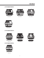
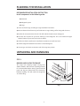
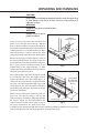
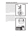
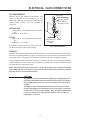
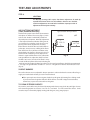
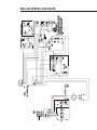
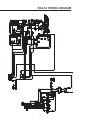
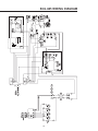
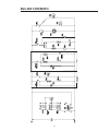
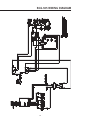
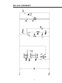
RGS SERIES RANGE
Installation Guide
MODELS:
RGS-305
RGS-366
RGS-364GL
RGS-364GD
RGS-484GG
RGS-486GL
RGS-486GD
RGS-485GD
A MESSAGE TO OUR CUSTOMERS
Thank you for selecting this DCS RGS Gas Range. Because of this appliance’s unique features we have
developed this Installation Guide. It contains valuable information on how to properly operate and
maintain your new appliance for years of safe and enjoyable cooking.
For your convenience, product questions can be answered by a DCS Customer Service Representative by
phone: 1-888-281-5698, Fax: 714-372-7004, email: [email protected], or by mail:
DCS
Attention: Customer Service
800 Skylab Road
Huntington Beach, CA 92647
www.dcsappliances.com
WARNING
If the information in this manual is not followed exactly, a fire or explosion
may result causing property damage, personal injury or death.
PRECAUTION
Do not store or use gasoline or other flammable vapors and liquids in the
vicinity of this or any other appliance.
FOR YOUR SAFETY
IF YOU SMELL GAS:
Do not try to light any appliance.
Do not touch any electrical switch; do not use any phone in your building.
Immediately call your gas supplier from a neighbor’s phone. Follow the gas
supplier’s instructions.
If you cannot reach your gas supplier, call the fire department.
Installation and service must be performed by a qualified installer, service
agency or the gas supplier.
PLEASE RETAIN THIS MANUAL FOR FUTURE REFERENCE.
1
TABLE OF CONTENTS
INTRODUCTION ..................................................................................................................................................................3
MODELS ....................................................................................................................................................................................4
PLANNING THE INSTALLATION ..............................................................................................................................5
UNPACKING AND HANDLING .............................................................................................................................5-7
VENTILATION REQUIREMENTS ...............................................................................................................................8
INSTALLING ANTI-TIP DEVICE .................................................................................................................................9
CABINET PREPARATION ......................................................................................................................................10-12
BACKGUARD INSTALLATION .................................................................................................................................13
ELECTRICAL / GAS CONNECTIONS .............................................................................................................13-14
TEST AND ADJUSTMENTS .................................................................................................................................14-15
INSTALLER FINAL CHECKLIST .........................................................................................................................15-16
WIRING DIAGRAMS ................................................................................................................................................17-23
RGS 48”Wiring Diagram . . . . . . . . . . . . . . . . . . . . . . . . . . . . . . . . . . . . . . . . . . . . . . . . . . . . . . . . . . . . . .17
RGS 36”Wiring Diagram . . . . . . . . . . . . . . . . . . . . . . . . . . . . . . . . . . . . . . . . . . . . . . . . . . . . . . . . . . . . . .18
RGS 36” / 48”Wiring Schematic . . . . . . . . . . . . . . . . . . . . . . . . . . . . . . . . . . . . . . . . . . . . . . . . . . . . . . . .19
RGS 485 Wiring Diagram . . . . . . . . . . . . . . . . . . . . . . . . . . . . . . . . . . . . . . . . . . . . . . . . . . . . . . . . . . . . . .20
RGS 485 Wiring Schematic . . . . . . . . . . . . . . . . . . . . . . . . . . . . . . . . . . . . . . . . . . . . . . . . . . . . . . . . . . . .21
RGS 305 Wiring Diagram . . . . . . . . . . . . . . . . . . . . . . . . . . . . . . . . . . . . . . . . . . . . . . . . . . . . . . . . . . . . . .22
RGS 305 Wiring Schematic . . . . . . . . . . . . . . . . . . . . . . . . . . . . . . . . . . . . . . . . . . . . . . . . . . . . . . . . . . . .23
HOW TO OBTAIN SERVICE........................................................................................................................................24
WARRANTY ..........................................................................................................................................................................25
2
INTRODUCTION
The DCS Professional series ranges are designed with a large number of features available in a
multitude of different combinations. Top burner sections, thermostatic griddles, and grills are available
as complete freestanding ranges.
The large capacity gas convection ovens of the RGS series are equipped with an in-oven gas infrared
broiler. The smaller gas oven found on the 48” RGS series is ideal for baking smaller dishes. All range
models require the installation of one of the two offered Backguards if installed with less than 12” to
combustible material. See pages 11 and 12.
IMPORTANT INSTALLATION INFORMATION
The RGS series ranges are tested in accordance with ANSI Z21.1 Standard for Household Cooking Gas
Appliances. These ranges must be installed in conjunction with a suitable overhead vent hood. See
Step 2 for ventilation requirements). Due to the professional high heat capacity of this unit, particular
attention should be paid to the hood and duct work installation to ensure it meets local building
codes. To eliminate risk of burns or fire by reaching over heated surface units, cabinet storage located
above the surface units should be avoided. Check local building codes for the proper method of range
installation. Local codes vary. Installation, electrical connections, and grounding must comply with all
applicable codes. In the absence of local codes, the range should be installed accordance with the
National Fuel Gas Code ANSI Z223-1-1998 and National Electrical Code ANSI / NFPA 70-1990. Be sure
that the unit being installed is set up for the kind of gas being used. The gas ranges are shipped from
the factory set and adjusted for natural gas or LP (propane), depending on the specific model ordered.
Verify that the range is compatible with gas supply at the installation site before proceeding
further. Return range to dealer if unit is not set for site gas supply.
3
MODELS
48” RGS RANGE MODELS
RGS-484GG
RGS-486GL
RGS-486GD
RGS-364GL
RGS-364GD
RGS-485GD
36” RGS RANGE MODELS
RGS-366
30” RGS RANGE MODELS
OVEN ON
HEATING
HEATING
DOOR LOCKED
RGS-305
4
PLANNING THE INSTALLATION
RECOMMENDED INSTALLATION INSTRUCTION
Install components in the following order:
A) Vent Hood
B) Backguard System
C) Range
1) Locate and level range according to range installation instructions.
2) Measure distance from floor to top of island trim on range adding 1/8” for backguard clearance.
3) Transfer this measurement to the wall. This will mark the bottom of your backguard.
4) From this line measure 28” up wall to mark top of 30” backguard. This is the minimum height
that the bottom of your vent hood can be installed.
6) Follow vent hood manufacturer’s installation instructions to install vent hood.
7) Follow backguard installation instructions to install backguard.
8) Connect gas and electric connections and slide range into position.
UNPACKING AND HANDLING
STEP 1:
MOVING AND PLACING THE RANGE
The ranges have shipping weights varying from
380lbs. to 600lbs. After removal of packing material,
it is recommended that the door(s), grates, front kick
panel, and drip pan (below knobs) be removed to
facilitate handling. This will reduce the weight for
ease of handling.
Kick Panel
Fig. 1
5
UNPACKING AND HANDLING
CAUTION:
Proper equipment and adequate manpower must be used in moving the range
to avoid damage to the unit or the floor. The unit is heavy and rests on
adjustable steel legs.
WARNING:
DO NOT lift range by the oven door handles!!
WARNING:
DO NOT remove the grill or
griddle assemblies!!
Left
Rear
Left
Rear
Shipping
Shipping
Screws Screws
It may be necessary to remove the oven doors and
knobs to pass through some doorways. With the
doors and knobs removed, a 29 1/16” (RGS-36/48) or
29 3/8” (RGS-305) wide opening is required. Without
removing the door, a 31 1/2”(RGS-36/48) or 30”(RGS305) wide opening is required. Remove the outer
carton and packing material from the shipping base.
Remove the kick panel by removing two screws at
the top and pulling forward. The range is held to the
skid by two bolts in the front behind the kick panel,
(fig. 1 pg. 5) and two L-brackets located on the
bottom flange of the range back (fig . 2). After
removing the bolts and brackets, the range must be
lifted and removed from the skid.
Due to the weight, a dolly with soft wheels should
be used to move this unit. The weight must be
supported, uniformly across the bottom (fig. 3). To
remove the door, open the door and hold it all the
way open. Close the hinge latches (fig. 4 pg. 7) and
release the door. The door can then be removed by
gently lifting and pulling the door, with the hinges
up and out of the frame.
Fig. 2
Range Must
Range Must
Be Uniformly
be Uniformly
Supported
Supportedon
Braces
on Braces
Electric and gas connections should be made (see
22"
page 13 & 14) before the range is slid into the
cabinet opening. If installing a full backguard with
LevelingLegs
Legs
Leveling
the range it should also be installed before the
Fig. 3
range is placed in its final position (refer to page 5)
for proper performance, the professional range
should be level. To achieve a flush fit of the range to adjoining countertops, it will be necessary to have
level cabinets (front to back, and left to right across opening of the range).
6
UNPACKING AND HANDLING
After checking the countertops for level and
before sliding the range into place, measure the
distance from the floor to the top of the counter
work surface in the rear left and right corners.
Adjust the corresponding rear corner of the range
to an equal height of the counter, as the rear
leveling legs are not accessible once the range is
pushed into place. Once the range is in place, the
front leg levelers can be accessed to level the
front of the range. Replace the kick panel and
oven doors by reversing the procedure described
previously. It is important that the two screws
retaining the kick panel are secure to prevent
accidental access to live electrical components
and wires (fig. 1 pg. 5).
DOOR HINGE
ROLLER
Door
Hinge
Roller
Lock
(close)
LOCK
(CLOSE)
UnLock
UN-LOCK
GRIDDLE AND GRILL LEVEL ADJUSTMENTS
The grill and griddle sections (if equipped) are
fastened in place at the front with screws. They
are designed to be stationary and not meant to
be removed for cleaning. The griddle has two
leveling screws beneath the rear flue cover which
can be used to adjust the griddle to the desired
slope. To access the leveling adjustment screws,
remove the griddle flue cover by lifting upwards.
The center screw is for shipping and should be
removed.
Fig. 4
Shipping Screw
(remove)
Outer Leveling
Screws (2)
Griddle Flue
Cover
Fig. 5
7
VENTILATION REQUIREMENTS
STEP 2:
A suitable exhaust hood must be installed above the range. The following chart indicates the
minimum blower capacity recommended for hood ventilation.
VENTILATION
UNIT
HOOD
BLOWER
STANDARD COUNTER
INSTALLATION
RECOMMENDATIONS
(24" Deep x Unit Width)
*48" RANGE
800-1200 CFM
**36" RANGE
600-800 CFM
ISLAND
INSTALLATION
RECOMMENDATIONS
(30" Deep x 36" at Bottom)
800-1200 CFM
600-1200 CFM
30" RANGE
500 CFM
500 CFM
* When installing a unit featuring a grill, select a blower on the high end of recommendation.
** For all 36” Range GL models a 1200 CFM ventilation unit is required.
CAUTION:
Ventilation hoods and blowers are designed for use with single wall ducting.
However, some local building codes or inspectors may require double wall
ducting. Consult local building codes and/or local agencies, before starting, to
ensure that hood and duct installation will meet local requirements.
Hood blower speeds should be variable to reduce noise and loss of heated or air conditioned
household air when maximum ventilation is not required. Normally, the maximum blower speed is
only required when using the grill.
For best smoke elimination, the lower edge of the hood should be installed a minimum of 30" to a
maximum of 36" above the range cooking surface, (page 10 & 11). If the hood contains any
combustible materials (i.e. a wood covering) it must be a minimum of 36" above the cooking surface.
Due to a high volume of ventilation air, a source of outside replacement air is recommended. This is
particularly important for tightly sealed and insulated homes. A reputable heating and ventilating
contractor should be consulted.
8
INSTALLING ANTI - TIP DEVICE
All ranges must have an anti-tip device
correctly installed as per the following
instructions. If you pull the range out
from the wall for any reason, make sure
that the device is properly engaged
when you push the range back against
the wall. If it is not, there is a possible
risk of the range tipping over and
causing injury if you or a child stand, sit
or lean on an open oven door.
(2) Wood Screws into
Back Wall (ALL
Installations)
(2)Small Holes for
Wood Installations
(2) Large Holes for
Concrete Installations
BACK
WALL
INCLUDED PARTS:
Included with this kit are:
F
E O GE
D
I
S AN
HT R R
G
I
R LL O
WA
(4) #10 x 2” wood screws,
(1) Anti-tip bracket, and (1) Installation
Instructions.
A
INSTALLING THE KIT:
Instructions are provided for wood and
cement floors. Any other type of
construction may require special installation techniques as deemed necessary
to provide adequate fastening of the Antitip bracket to the floor and wall. The use of
this bracket does not preclude tipping of
the range when not properly installed.
Fig. 6
A=
1/2”
5/8”
7/8”
Model
Series
RGS-48
RGS-36
RGS-305
WOOD CONSTRUCTION:
Place the bracket against the back wall, into the
right rear corner where the range is to be located.
Leave a gap between the wall (or side of range) and
the bracket (see fig. 6). Drill (2) 1/8” diameter pilot
holes in the center of the small holes. A nail or awl
may be used if a drill is not available. Fasten the
bracket securely to the floor and wall.
CONCRETE OR CEMENT CONSTRUCTION:
Hardware Required:
WARNING
ALL RANGES CAN TIP
INJURY COULD RESULT
INSTALL ANTI-TIP
BRACKET PACKED
INSIDE OVEN
SEE INSTRUCTIONS
(2) sleeve anchors, lag bolts, and washers (not
provided). Locate the bracket as described above.
Fig. 7
Drill the recommended size holes for the hardware.
Install the sleeve anchors into the holes and then install the lag bolts through the bracket. The bolts
must be properly tightened as recommended for the hardware. Fasten the bracket securely to the
floor and wall.
ONCE INSTALLED:
Complete the range installation per the instructions provided with the product. Check for proper
installation of the range and Anti-tip device by grasping the back of the unit and carefully attempt to
tilt the range forward.
9
CABINET PREPARATION
STEP 4:
1) The range is a free standing unit. If the unit is to be placed adjacent to cabinets, the clearances
shown in fig. 8 (RGS-48 & 36) & fig. 10 (RGS-305) are required. The same clearances apply to island
installations.
2) The range can be placed in various positions with respect to the cabinet front, with the front either
flush or projecting, depending on the countertop depth.
3) The gas and electrical supply should be within the zones shown (fig. 8, 10, & 14).
4) The maximum depth of over head cabinets installed on either side of the hood is 13”.
5) Any openings in the wall behind the range and in the floor under the range must be sealed.
6) When there is less than a 12” clearance between combustible material and the back edge of the
range, (above the cooking surface) a DCS backguard must be installed, (figs. 9A & B & 11 page 12
and 13). When clearance to combustible material is over 12”no backguard is necessary (fig. 9A page
11). Backguards must be ordered separately. Fig. 9A & 11, indicate the space required for each
type of backguard.
7) Always keep the appliance area clear and free from combustible materials, gasoline and other
flammable vapors and liquids.
8) Do not obstruct the flow of combustion and ventilation air to the unit.
Min. 48" Wide Hood
Min. 36" Wide Hood
12" Min. to combustible
material , each side
13"
Max.
18" Min.
A
B
12
A
cooking surface
3-1/2"
Electrical Supply
35-3/8" Max. For Level Counter,
36-3/4" Max. With Range
Leveling Legs Fully Extended
3-1/4"
Gas Supply
A B
RGS 48 models = 8" 16"
RGS 36 models = 4" 12"
As defined in the
“National Fuel Gas Code”
(ANSI Z223.1, Latest Edition).
The range height is adjustable. The level of the
range top must be at the same level or above the countertop level.
Fig. 8 RGS 48” & 36” Models Only
10
CAUTION:
36" Min. to
combustible
material ,
from cooking
surface
CABINET PREPARATION
A
B
12" Min. to
Combustibles
without backguard
G
36" Min. to
Combustibles
H
A
C
B
C
0” Clearance
0” Clearance
E
F
I
D
J
Fig. 9 RGS 48” & 36” Models Only
RGS 48 Models
RGS 36 Models
A
B
C
28-1/8”
28-1/8”
10-1/8”
10-1/8”
2”
2”
D
E
35 1/2” min.-37” max. 30-1/4”
35 1/2” min.-37” max. 30-1/4”
11
F
44-1/2”
44-1/2”
G
28-1/4”
28-1/4”
H
1-5/16”
1-5/16”
I
25”
25”
J
WIDTH
27-3/8” 47-7/8”
27-3/8” 35-7/8”
CABINET PREPARATION
Min. 30" Wide Hood
13"
CAUTION:
36" Min. to
combustible
material ,
from cooking
surface
12" Min. to combustible Max.
material , each side
18" Min.
16" 2"
cooking surface
4"
Electrical and
Gas Supply
35-3/8" Max. For Level Counter,
36-3/4" Max. With Range
Leveling Legs Fully Extended
As defined in the
“National Fuel Gas Code”
(ANSI Z223.1, Latest Edition).
The range height is adjustable. The level of the
range top must be at the same level or above the countertop level.
Fig. 10 RGS 305 Models Only
12" Min. to
Combustibles
without backguard
G
36" Min. to
Combustibles
H
A
C
B
C
D
0” Clearance
0” Clearance
E
F
J
I
Fig. 11 RGS 305 Models Only
A
B
C
RGS 305 Models 28-1/8” 10-1/8” 2”
D
E
F
35-1/2” min. 37” max.
30”
44”
12
G
H
I
27-1/2” 1-5/16” 24-1/4”
J
26-3/4”
WIDTH
29-7/8”
BACKGUARD INSTALLATION
BACKGUARD KITS:
Wall Mount
Full Backguard
The backguard is located as shown in Fig. 12.
Secure the backguard to the wall behind the
range. Specific instructions for installation of
the full backguard or low backguard can be
found packaged with the backguard. See
also page 5, “Planning The Installation
Section”. A backguard must be installed when
there is less than a 12” clearance between
combustibles and the back of the range
(above the cooking surface) see fig. 11.
(Model #’s BGS-3030,
BGS-3036, BGS-3048)
Wall Mount
Low Backguard
(Model #’s BGS-1230,
BGS-1236, BGS-1248)
Fig. 12
ELECTRICAL / GAS CONNECTIONS
STEP 5:
ELECTRICAL CONNECTIONS
Receptacle
ReceptacleBox
Box
Plate
CoverCover
Plate
Power Requirements Range:
120 VAC, 60 Hz., single phase
RGS-305: 4 Amp. Max.
RGS-36: 7 Amp. Max.
RGS-48: 13 Amp. Max.
Three Three
Prong
Prong
Plug
Plug
(use 15 Amp. circuit)
Always disconnect electric supply cord from the
wall outlet or service disconnect before servicing
this appliance. Observe all governing codes and
ordinances when grounding, in absence of
which, observe National Electrical Code
ANSI / NFPA No. 70-1990.
Three Prong
Three
Prong
Receptacle
Receptacle
Fig. 13
RECOMMENDED GROUNDING METHOD
This appliance is factory equipped with a power
supply cord with a three-prong grounding plug (with polarized parallel blades). It must be plugged
into a mating grounding, type receptacle, connected to a correctly polarized 120 volt circuit. If the
circuit does not have a grounding type receptacle, it is the responsibility and obligation of the installer
to have the existing receptacle changed to a properly grounded and polarized receptacle in
accordance with all applicable local codes and ordinances by a qualified electrician. In the absence of
local codes and ordinances, the receptacle replacement shall be in accordance with the National
Electrical Code.
The third prong should not, under ANY circumstances, be cut or removed.
13
ELECTRICAL / GAS CONNECTIONS
GAS REQUIREMENTS
Verify the type of gas supplied to the location. The
range are shipped from the factory set up and
adjusted for natural gas or LP (propane), depending on
specific model ordered. The unit CANNOT be
converted.
Gas
GasSupply
Supply
Flex Line
Line to
Flex
ToRange
Range
ManualShut-Off
Shut-Off
Manual
Valvemust
MustbeBe
Valve
EasilyAccessible
Accessible
Easily
NATURAL GAS
Elec
Connection: 1/2” N.P.T. Minimum 5/8” dia. flex
line.
Pressure: 6” to 14”W.C.
LP GAS
Connection: 1/2” N.P.T. Minimum 5/8 dia. flex
line.
Pressure: 11” to 14”W.C.
A regulator is required at the LP source to provide a
maximum of 14”W.C. to the range regulator.
2” 2"
Maximum
Maximum
Protrusion
From
Protrusion
from Wall
Wall
For Gas
for Gas
Supply
Supply
Fig. 14 All RGS Models
HOOK-UP
A manual valve must be installed external to the appliance, in an accessible location from the front for
the purpose of shutting off the gas supply. The supply line must not protrude beyond the back of the
unit. Make sure the gas supply is turned off at the wall valve before connecting the appliance.
The gas supply connections should be made by a qualified technician and in accordance with local
codes or ordinances. In the absence of a local code, the installation must conform to the National Fuel
Gas Code ANSI 223.-1988, latest edition.
NOTE: The flex line for the gas supply must be metal and be approved by an approved certifying
agency (AGA, CGA, CSA, or UL). Never use a hose made of rubber or other synthetic material, as the heat
may cause the hose to melt and develop leaks.
CAUTION:
The appliance must be isolated from the building’s gas supply piping system
by closing its individual manual shut-off valve during any pressure testing of
the gas supply piping system at test pressures equal to or less than 1/2 psig
(3.5kPa.).
The appliance and its individual shut-off valve must be disconnected from
the gas supply piping system during any pressure testing of the system at the
test pressures in excess of 1/2 psig (3.5kPa.). When checking the manifold gas
pressure, the inlet pressure to the regulator should be at least 7.0” W.C. for
natural gas or 12.0” for LP.
14
TEST AND ADJUSTMENTS
STEP 6:
CAUTION:
For Warranty coverage, DCS requires that burner adjustments be made by
a qualified technician at the time of installation. Extreme care should be
used when adjustments are made after installation. Improper or lack of
adjustments will void your warranty.
AIR SHUTTER ADJUSTMENT
(Oven, Griddle or Grill only)
TypicalTypical
Section
Flame
SectionofofProper
Proper Flame
Check for the proper burner flame characteristics
(Griddle)
(Grill
and adjust air shutters if necessary (fig. 15). Each
(Grill)
(Griddle)
valve and air shutter is individually tested and
adjusted prior to shipment. Normally adjustment
is not required, however, vibration during transit,
1-1/2”
1-1/2" - -2"2”
3/8”
5/8”
gas conversion or variations in the local gas sup3/8"-- 5/8"
ply may make minor adjustments necessary.
Burner flames should be blue and stable with no
yellow tips, excessive noise or lifting of the flame
from the burner. If any of these conditions exist,
check that the air shutter or burner ports are not
blocked. If this condition persists, adjust the air
shutter as required. If the flame is too yellow, indiFig. 15
cating insufficient air, adjust the shutter counterclockwise to increase air inlet. If the flame is noisy
or tends to lift away from the burner, indicating too
much air, turn the shutter clockwise to reduce air. The open burner flames should be approximately
1-1/2" high. The griddle flames should be 1-1/2" to 2". The grill burner flames should be 3/8” to 5/8”
(fig. 15).
SURFACE BURNERS
The surface burners are not adjustable. Proper operation is achieved when the correct orifices for gas
supply are installed at the factory, based on model ordered.
If the open top burner does not ignite, check the spark igniter by listening for a clicking sound.
If you do not hear the igniter click, turn off the burner. Check for a tripped circuit breaker,
blown fuse, or poor wire connection to the igniter.
TO CLEAN EXTERIOR SURFACES
The stainless steel surfaces may be cleaned by wiping with a damp soapy cloth. Any mild glass cleaner
will remove fingerprints and smears. Do not use steel wool as it will scratch this surface. Small
scratches may be removed by lightly sanding, with the grain, using 120 grit paper.
15
INSTALLER FINAL CHECKLIST
GENERAL
Placement of unit.
Specified clearance maintained to cabinet surfaces.
Unit Level - front to back, side to side.
All packaging material and tie straps removed, drip pans clean and empty.
Backguard attached if there is less than 12" clearance above the cooking surface to combustibles
behind unit.
Radiant tray placed in grill unit (if equipped). The two grill racks in place.
ELECTRICAL
Receptacle with 15 ampere over-current protection is provided for service cord connection.
Adequate ground connection.
Front kick panel in place and two (2) screws secure.
GAS SUPPLY
Connection: 1/2 NPT with a minimum 5/8" diameter flex line. Site gas supply is compatible with
range model, & sufficient pressure is available (see gas requirements pg. 13).
Manual gas shut-off valve installed in an accessible location.
Unit tested and free of gas leaks.
OPERATION
All internal packing materials removed. Check below grate, pans and drip drawers.
Grill compartment seated and does not rock (not all models).
Bezels centered on burner knobs and knobs turn freely.
Each burner lights satisfactorily, both individually and with other burners.
Flame adjustment made on air shutter of each oven, griddle, or grill burner, (fig. 15).
Griddle is level and does not rock (not all models).
Drip trays are properly in place and pull out freely (Not all models).
Oven door hinges seated and door opens and closes properly.
Burner grates correctly positioned, level, and do not rock.
16
RGS-48 WIRING DIAGRAM
17
RGS-36 WIRING DIAGRAM
18
RGS-48/36 SCHEMATIC
19
RGS-485 WIRING DIAGRAM
20
RGS-485 SCHEMATIC
21
RGS-305 WIRING DIAGRAM
22
RGS-305 SCHEMATIC
23
HOW TO OBTAIN SERVICE
For warranty service, contact DCS Customer Service at (888) 281-5698. Before you call, please have
the following information ready:
Model Number
Serial Number
Date of installation
A brief description of the problem
Your satisfaction is of the utmost importance to us. If a problem cannot be resolved to your
satisfaction, please write or fax us at:
Write:
DCS
Attention: Consumer Relations
5800 Skylab Road
Huntington Beach, CA 92647
Fax us at: (714) 372-7004
email: [email protected]
BEFORE YOU CALL FOR SERVICE:
1) Is the circuit breaker tipped or the fuse blown?
2) Is there a power outage in the area?
24
WARRANTY
Length of Warranty:
One (1) Year Full parts and Labor Covers the entire product.
Five (5) Year Surface burners, oven burner.
Ten (10) Year Porcelain oven, porcelain inner door panel. Oven racks and grates.
DCS Will Pay For
All repair labor and parts found to be defective due to materials or workmanship for one full year “IN
HOME” warranty during the first year of ownership. This does not apply if the unit was subjected to
other than normal household use. Service must be provided by Authorized Factory Agent during
normal working hours. No charges will be made for repair or replacement at the location of initial
installation or factory for parts returned pre-paid, through the dealer and claimed within the warranty
period, and found by DCS to be defective.
Replacement will be F.O.B. DCS, and DCS will not be liable for any transportation costs, labor costs, or
export duties. This warranty shall not apply, nor can we assume responsibility for damage that might
result from failure to follow manufactures instructions or local codes, where the appliance has been
tampered with or altered in anyway or which, in our judgement, has been subjected to misuse,
negligence, or accident. Implied warranty shall not extend beyond the duration of this written
warranty. This warranty is in lieu of all warranties expressed or implied and all other obligations or
liability in connection with the sale of this appliance.
DCS Will Not Pay For
Installation or start-up.
Shipping damage.
Service by an unauthorized agency.
Damage or repairs due to service by an unauthorized agency or the use of unauthorized parts.
Service during other than normal working hours.
Improper installation, such as improper hook-up, etc.
Service visits to teach you how to use the appliance; correct the installation; reset circuit
breakers or replace home fuses.
Repairs due to other than normal household use.
Damage caused from accident, abuse, alteration, misuse, incorrect installation or installation not
in accordance with local codes.
Units installed in non-residential application such as day care centers, bed and breakfast
centers, churches, nursing homes, restaurants, hotels, schools, etc.
This warranty applies to appliances used in residential applications; it does not cover their use in
commercial situations. This warranty is for products purchased and retained in the 50 states of the
U.S.A., the District of Columbia and Canada. This warranty applies even if you should move during the
warranty period. Should the appliance be sold by the original purchaser during the warranty period,
the new owner continues to be protected until the expiration date of the original purchaser’s warranty
period. This warranty gives you specific legal rights. You may also have other rights which vary from
state to state.
25
NOTES
26
NOTES
27
NOTES
28
5800 Skylab Road, Huntington Beach, CA 92647
Tel: 714.372.7000 • Fax: 714.372.7001
Customer Service: (888) 281-5698
www.dcsappliances.com
As product improvement is an ongoing process at DCS, we
reserve the right to change specifications or design without
notice.
P/N 17456 Rev. A
Litho in USA 08/2002