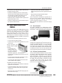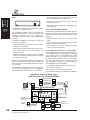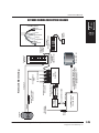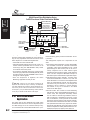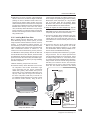
1
LEVITON INTEGRATED NETWORKS
Installation Manual
for Residential
Installation Manual
for Residential Structured Wiring
www.leviton.com/lin
www.levitonvoicedata.com
Tech Line: 800-722-2082
Customer Service: 800-323-8920
W-818/E1-35M rs
E-1
Structured Wiring
Version 2.0
INSTALLATION MANUAL FOR
RESIDENTIAL STRUCTURED WIRING
This manual provides a comprehensive description of issues related to the fast evolving subject
known as residential structured wiring. It covers industry standards, warranties, installer certification,
ordinances, tools, job planning, system design and installation techniques. It was our goal to produce
a document which helps the designer or contractor with the entire process of planing and installing a
system which is compliant with today’s industry standards.
Contact Information
Contact
Function
Phone
Fax
Customer Service
Ordering product
800-323-8920
800-832-9538
Tech Line
Tech support
800-722-2082
425-483-5270
Sales Support
Literature requests
800-922-6229
425-485-0112
Visit us on the web at :
www.leviton.com/lin
www.levitonvoicedata.com
Leviton Voice and Data Division: 800-722-2082
Leviton Canada:
800-469-7890
Leviton S.A. de C.V. (Mexico):
525-386-0073
Note: Because Leviton engages in a continuous program of product improvement data in this manual
is subject to change without notice.
© Copyright Leviton Manufacturing Co., Inc. 2001. All rights reserved.
TABLE OF CONTENTS
Section
Page No.
1 Introduction to Leviton Integrated Networks Systems
1.1 Structured Media Subsystems ........................................................................................................................ 1-2
1.2 Types of Structured Media Subsystems..........................................................................................................
1.2.1 Essential Infrastructure ..........................................................................................................................
1.2.2 Enhanced Infrastructure ........................................................................................................................
1.2.3 Application Subsystems (Multi-room Video, Multi-Location Stereo,......................................................
Multi-Location Networking, Family and Home Monitoring)
1-2
1-2
1-2
1-2
2 Leviton Quality and Warranty
2.0 Quality Statement, Quality Processes, ISO 9000 Leviton Integrated Networks ............................................. 2-1
Structured Media™ Warranty
3 Certification Policy
3.0 Requirements for Installer Certification, Certification, Certification Checklist ................................................ 3-1
4 Local Ordinances, Covenants, and Service Provider Coordination
4.0 Local Ordinance, Covenants and Builder Considerations, Service Provider Coordination............................ 4-1
5 Recommended Accessories, Tools, and Test Equipment
5.1 Mud Rings Instead of Electrical Boxes for Drop Locations ........................................................................... 5-1
5.2 Cable Routing, Dressing, and Strain Relief..................................................................................................... 5-1
5.2.1. Pulling Low-Voltage Wiring Through Wood and Metal Framing Members ........................................... 5-2
5.3 Tools for Pre-Wire (Rough-In) Installation ........................................................................................................ 5-3
5.4 Tools for Trim Out Installation........................................................................................................................... 5-3
5.5 Termination Equipment for Category 5 or 5e Cable........................................................................................ 5-3
5.6 Termination Equipment for RG-6 and RG-6 Quad Shield Cable..................................................................... 5-4
5.6.1 Other Tools for Installing Leviton Integrated Network .......................................................................... 5-4
5.7 Test Equipment for Category 5 or 5e Installations .......................................................................................... 5-4
5.8 Test Equipment for Telephone Installations ..................................................................................................... 5-5
5.9 Test Equipment for Coaxial Cable Installations ............................................................................................... 5-6
5.10 Check List (of above) .................................................................................................................................... 5-6
5.11 What You Need to Know................................................................................................................................ 5-6
6 Description of Leviton Integrated Network Systems
6.1 Essential Infrastructure Platform for Single Family Homes ............................................................................. 6-1
6.1.1 Series 280 SMC ..................................................................................................................................... 6-2
6.2 Essential Infrastructure Platform for a Multiple Dwelling Unit ........................................................................ 6-2
6.2.1 Series 100 SMC ..................................................................................................................................... 6-3
6.2.2 Series 140 SMC ..................................................................................................................................... 6-3
For more information call your Leviton representative or the Leviton Technical Hotline at 800-722-2082
© Copyright 2001 Leviton Manufacturing Co., Inc.
I
6.3 Enhanced Infrastructure Platform .................................................................................................................
6.3.1 Series 420 SMC ..................................................................................................................................
6.3.2 Media Versatile Panel..........................................................................................................................
6.3.3 Wallplates, Jacks and Connections ....................................................................................................
6-4
6-4
6-4
6-5
6.4 Distributed Video (CATV, DSS, other Services) ...........................................................................................
6.4.1 Passive Video Splitters........................................................................................................................
6.4.2 Satellite Signal Distribution .................................................................................................................
6.4.3 Modules with Built-in Amplifiers ..........................................................................................................
6-5
6-5
6-5
6-5
6.5 Multi-Room Audio/Video Options ..................................................................................................................
6.5.1 Stereo Modulator.................................................................................................................................
6.5.2 DC Power Distribution Module............................................................................................................
6.5.3 Multi-Room InfraRed (IR) Repeater ....................................................................................................
6-6
6-6
6-6
6-7
6.6 Multi Location Networking............................................................................................................................. 6-7
6.6.1 10 Base-T Network Hub...................................................................................................................... 6-7
6.6.2 10/100 Base-T Network Hub............................................................................................................... 6-8
6.7 Multi-Room Stereo Sound Application ..........................................................................................................
6.7.1 Audio Controls ....................................................................................................................................
6.7.2 Multi-Room InfraRed (IR) Repeater ....................................................................................................
6.7.3 Speakers .............................................................................................................................................
6-8
6-9
6-9
6-9
6.8 Home Video Security Monitoring ..................................................................................................................
6.8.1 Video Sequencer ................................................................................................................................
6.8.2 Media Center Modulator .....................................................................................................................
6.8.3 RF Notch Filter ....................................................................................................................................
6-10
6-10
6-11
6-11
7 System Design and Placement—Laying Out the Basics
7.1 Laying out the Basics on the Floor Plans ..................................................................................................... 7-1
7.2 System Choices and Options (Floorplans and Planning Charts) ................................................................. 7-1
7.3 Mud Ring Locations ......................................................................................................................................
7.3.1 Location Matrix by Type ......................................................................................................................
7.3.2 Number per Room ..............................................................................................................................
7.3.3 Installation Height above Floor ...........................................................................................................
7-8
7-8
7-8
7-8
7.4 Cabling Types and Counts for Each Location ..............................................................................................
7.4.1 Telephone and Data Cable: Cat 5 or 5e UTP .....................................................................................
7.4.2 Video Cable for CATV, TV, DSS, and Monitoring: .............................................................................
7.4.3 Power Cable for Video Monitoring Camera: Cat 5 or 5e UTP ...........................................................
7.4.4 Speaker Cable for Multi Location Stereo ............................................................................................
7.4.5 Infrared (IR) Remote Control Target and Emitter Cable ....................................................................
7.4.6 Hi-speed Fiber Optic Cable................................................................................................................
7.4.7 Non-metallic Tubing (ENT and PVC) for Future Cable Runs ..............................................................
7-9
7-9
7-9
7-9
7-9
7-10
7-10
7-11
7.5 Wall Plate Configurations ..............................................................................................................................
7.5.1 QuickPort Flush-Mount Plates.............................................................................................................
7.5.2 QuickPort Decora Plus WallPlate Inserts and Wallplates ..................................................................
7.5.3 Wall Mount Telephones .......................................................................................................................
7-11
7-11
7-12
7-12
7.6 Structured Media Center ..............................................................................................................................
7.6.1 General Location.................................................................................................................................
7.6.2 Height Above the Floor .......................................................................................................................
7.6.3 Horizontal Location .............................................................................................................................
7-12
7-12
7-12
7-12
7.7 Structured Media Center Components and Devices.................................................................................... 7-13
7.7.1 Recommended Placements of Cables and Components .................................................................. 7-13
7.8 What You Need to Know ............................................................................................................................... 7-13
II
For more information call your Leviton representative or the Leviton Technical Hotline at 800-722-2082
© Copyright 2001 Leviton Manufacturing Co., Inc.
Installation Manual
8 Pre-Wire Installation
8.1 The Walk-Through ......................................................................................................................................... 8-1
8.1.1 The Reality of the Job and the Installation.......................................................................................... 8-1
8.2 Mud Rings ..................................................................................................................................................... 8-2
8.2.1 Location of Mud Rings ........................................................................................................................ 8-2
8.2.2 Mounting Mud Rings ........................................................................................................................... 8-2
8.3 Structured Media Center...............................................................................................................................
8.3.1 Location Matters..................................................................................................................................
8.3.2 Mounting Your SMC ............................................................................................................................
8.3.3 Grommets or Plastic Bushings............................................................................................................
8.3.4 Cable Entry to the SMC ......................................................................................................................
8.3.5 Powering the SMC ..............................................................................................................................
8.3.6 AC Power Module ...............................................................................................................................
8.3.7 Installing the AC Power Module..........................................................................................................
8.3.8 Grounding the SMC ............................................................................................................................
8-2
8-2
8-3
8-4
8-4
8-4
8-4
8-4
8-6
8.4 Structured Cabling (Pre-wire) .......................................................................................................................
8.4.1 Cable Topology ...................................................................................................................................
8.4.2 Cable Routing, Dressing and Strain Relief .........................................................................................
8.4.3 Cable Bend Radius .............................................................................................................................
8.4.4 Service Loops ....................................................................................................................................
8.4.5 Labeling ..............................................................................................................................................
8.4.6 Label Placement .................................................................................................................................
8.4.7 Wiring Chart ........................................................................................................................................
8-6
8-7
8-7
8-9
8-9
8-9
8-9
8-10
8.5 Pre-Wire for Individual Devices..................................................................................................................... 8-10
8.6 Volume Control and Speakers Location Considerations .............................................................................. 8-11
8.7 Wiring for the Decora Digital Volume Controls ............................................................................................. 8-11
8.8 What You Need to Know ............................................................................................................................... 8-11
8.9 Summary of Installation Rules and Precautions ........................................................................................... 8-11
8.9.1 Standard General Practices for Installers ........................................................................................... 8-13
8.9.2 Wire and Cable Installation ................................................................................................................. 8-13
9 Installation Trim Out
9.1 QuickPort Jacks, Connectors, and Wallplates ............................................................................................
9.1.1 Terminating Cat 5 or 5e Jacks ............................................................................................................
9.1.2 Terminating Coaxial Connectors .........................................................................................................
9.1.3 Terminating at Other Connectors ........................................................................................................
9.1.4 Placing QuickPort Connectors and Jacks into QuickPort Wall Plates ...............................................
9.1.5 Labeling and Label Placement ...........................................................................................................
9-1
9-1
9-2
9-3
9-3
9-3
9.2 Structured Media Center Devices (SMC Trim Out)....................................................................................... 9-3
9.2.1 Placing and Mounting Devices ........................................................................................................... 9-3
9.2.2 Routing and Dressing Cable in the SMC............................................................................................ 9-3
9.3 Essential Infrastructure Platform ...................................................................................................................
9.3.1 Basic Telephone Connections Using Bridged Telephone Module .....................................................
9.3.2 Category 5 Voice and Data Module....................................................................................................
9.3.3 Coaxial Video Distribution Connections Using Passive Splitter .........................................................
9-4
9-4
9-5
9-5
9.4 Enhanced Infrastructure................................................................................................................................ 9-6
9.4.1 Telephone Connections Using Telephone Distribution and Cat 5 Modules ....................................... 9-6
9.4.2 Installing the DC Power Supply Module ............................................................................................. 9-7
For more information call your Leviton representative or the Leviton Technical Hotline at 800-722-2082
© Copyright 2001 Leviton Manufacturing Co., Inc.
III
9.5 Multi-Location Networking............................................................................................................................. 9-8
9.5.1 Video Distribution (Coaxial)................................................................................................................. 9-11
9.6 Multi-Room Stereo Sound Application ..........................................................................................................
9.6.1 Multi-Room Considerations .................................................................................................................
9.6.2 Installing and Connecting Analog Volume Controls ...........................................................................
9.6.3 Setting Impedance for the Leviton Impedance Matching Volume Controls.......................................
9.6.4 Installing the Decora Digital Volume Controls ....................................................................................
9.6.5 Preparing the Speakers for Mounting .................................................................................................
9.6.6 Installing the Speakers........................................................................................................................
9-13
9-13
9-15
9-15
9-16
9-17
9-17
9.7 Multi-Room Audio/Video Options .................................................................................................................. 9-17
9.7.1 Stereo Modulator................................................................................................................................. 9-18
9.8 Multi-Room Stereo Infra-Red (IR) Control Connection.................................................................................. 9-18
9.8.1 Installing Targets and Emmiters.......................................................................................................... 9-18
9.9 Indoor/Outdoor Home Camera Monitoring ...................................................................................................
9.9.1 Indoor Security Camera ......................................................................................................................
9.9.2 Installing the Decora Camera .............................................................................................................
9.9.3 Mounting the Decora Camera.............................................................................................................
9.9.4 Outdoor Camera .................................................................................................................................
9.9.5 Mounting the Outdoor Camera ...........................................................................................................
9.9.6 Powering the Cameras........................................................................................................................
9.9.7 Direct Video Monitoring.......................................................................................................................
9.9.8 Network Video Monitoring ...................................................................................................................
9-19
9-20
9-20
9-20
9-21
9-21
9-21
9-21
9-22
9.10 Multi-Room Video Application..................................................................................................................... 9-27
9.10.1 Installing Multi-Room Video............................................................................................................. 9-28
9.11 What You Need to Know Check List ........................................................................................................... 9-29
9.12 Terminating the Cable ................................................................................................................................. 9-29
10 Testing and Test Documentation
10.1 Labels.......................................................................................................................................................... 10-1
10.2 Documentation ............................................................................................................................................ 10-1
10.3 Visual Inspection Immediately after Pre-Wire ............................................................................................. 10-1
10.4 Basic Testing ...............................................................................................................................................
10.4.1 Cat 5 or 5e UTP in Non-Cat 5 or 5e Compliant Cable Runs ..........................................................
10.4.2 Audio Cable ....................................................................................................................................
10.4.3 RG-6 Quad Shield Cable ................................................................................................................
10-1
10-2
10-3
10-3
10.5 Category 5 or 5e Testing............................................................................................................................. 10-3
10.6 Final Residential Wiring Verification ............................................................................................................ 10-5
10.7 Speaker Cabling Tests ................................................................................................................................ 10-6
10.8 Documentation of Test Results.................................................................................................................... 10-7
Appendix A Glossary
Appendix B Frequently Asked Questions
IV
For more information call your Leviton representative or the Leviton Technical Hotline at 800-722-2082
© Copyright 2001 Leviton Manufacturing Co., Inc.
INTRODUCTION
1
INTRODUCTION
to Leviton
Integrated
Networks and
Structured
Media Systems
1 Introduction to Leviton
Integrated Networks and
Structured Media™ systems
Leviton Integrated Networks purpose.
More than ever, today’s technologies are confronting
homeowners with an expanded range of choices—and
some hard decisions as a result. The three standard
television channels of the 1950’s and 60’s, for example,
have exploded into some hundreds of digital cable and
satellite options, while the quality of the incoming
audio/video signal has evolved to the point where the
luxury of a home theater is increasingly considered a
standard feature. Home telephone lines are now tied
up far longer on the internet than with actual phone
conversations, to the point where the phrase on-line
refers more to a way of life than a connection status.
People are considering high-speed access alternatives for their homes which, just a short time ago, were
only available to a handful of large corporations.
On top of all these new incoming home technologies,
age-old needs such as security, convenience and comfort are raising homeowner expectations in every area.
Smarter lighting, better power quality and more comprehensive home control are just some of the applications making the leap from luxury to everyday use.
Since 1906, the name Leviton has been synonymous
with quality in connectivity. Perfecting the concept of
residential wiring devices at the beginning of one century gave Leviton the head start needed to bring
today’s homes and businesses into the next one. From
multimedia panels to surge-protected AC outlets, from
three-way lighting to Category 5 or 5e cabling,
Leviton’s highest level of products, skills and
resources are combined in Leviton Integrated
Networks, an ongoing residential system program that
uses the layered subsystem approach to make
upgrading simpler and more sensible.
Subsytems for Today’s Wired Home
Leviton Integrated Networks start with Structured
Media™ subsystems designed for those with high
expectations for their high technology homes,
designed with the flexibility to handle everything from
high-speed internet to high-definition TV. From there,
Lighting Control subsystems set the ambience needed to fully complement today’s wired homes. Home
Control subsystems add comfort, convenience and
security by making the home more accessible and livable, as well as making it look more lived-in—the first
line of defense according to the security experts.
Power Quality subsystems help to protect the home’s
technology investment by shielding home offices and
entertainment centers from potentially damaging
power line problems. Finally, Special Needs upgrades
give everyone, young and old, easier access in a
friendlier living environment.
The different Leviton Integrated Networks subsystems
have a common baseline that places them a cut above
the rest: each component is derived from the more
demanding realm of commercial and professional applications. Leviton’s data communications products used
in Structured Media, for example, are considered “high
end” in high-speed commercial networks, while the
surge-protection components comprising Leviton Power
Quality are rated for “mission-critical” use in hospitals
and laboratories. As standard equipment in high-profile,
high-style applications ranging from restaurants to art
galleries, Leviton’s Lighting Controls share an equally
impressive set of credentials. The Lighting Control,
Home Control, Power Quality, and Special Needs subsytems are covered in other Leviton Documentation.
This Installation Manual focuses on the Structured Media
subsystems involving voice, data, video, audio, and
video monitoring for the home.
For more information call your Leviton representative or the Leviton Technical Hotline at 800-722-2082
© Copyright 2001 Leviton Manufacturing Co., Inc.
1-1
1
INTRODUCTION
to Leviton
Integrated
Networks and
Structured
Media Systems
Leviton Integrated Networks presents these most desired
home features in pre-configured subsystem packages,
with system design, component placement, wiring and
installation outlined in easily-followed steps. With the
Leviton Integrated Networks program, the skilled contractor is positioned as a system integrator, capable of
providing their clients with the latest in home technologies and features—all provided and backed by Leviton,
the first name their customers trust for their electrical
needs. Whether the job calls for a simple upgrade to
Category 5 or 5e wiring or a fully-automated networked
home, Leviton Integrated Networks has the product, system and installation plan needed to ensure success.
1.1 Structured Media™
subsystems.
Structured Media refers to a subsystem that supports
the range of information, communication and entertainment technologies available to the modern home—
including telephone, high-speed internet, cable and
satellite TV (analog and digital), and more. Leviton’s
Structured Media takes the concept of structured
cabling, as practiced in demanding commercial applications for business and office networking, and combines it with multimedia to accommodate the convergence of audio/video and personal computers, of telephone and internet services, and much more.
Most important, Leviton’s Structured Media program
gives end-users a standards-compliant system—an
important consideration today where inadequate or
substandard performance may mean a lot more than a
call-back. Each properly installed Leviton Structured
Media subsystem is designed to meet TIA-570A, the
most stringent residential standard proposed by the
Telecommunications Industries Association.
1.2 Types of Structured Media
subsystems.
Structured Media subsystems can handle needs ranging from cable TV and telephone in several rooms to a
Home Area Network (HAN) for a small office or homebased business much like a LAN or Local Area
Network. Every Leviton Structured Media subsystem is
capable of growing to keep up with the user, with “open
architecture” centralized enclosures and wallplates.
Leviton Integrated Networks Systems are built on two
primary platforms: Essential Infrastructure and
Enhanced Infrastructure. Various applications can be
added to these platforms to meet the particular needs of
1-2
the builder, contractor, and home owner. Each of these
applications require additional dedicated pre-wiring.
1.2.1 Essential Infrastructure Platform: this is the base
level for residential structured cabling, ideal for
builders and end-users who want the marketability and assurance of a Category-rated
cabling system and whose needs include telephone and cable TV with the possibility of home
networking in the future. This platform includes
telephone, data, and video distribution. NOTE:
The Leviton Essential infrastructure plan uses
the same cabling as the Enhanced plan, and
can be easily upgraded.
1.2.2 Enhanced Infrastructure Platform: for homes with
multiple PC’s, telecommuters working at home,
and anyone who may require a network. The
Enhanced infrastructure level includes Ethernet
for networking PC’s and peripherals together as
in an office, and provides more room to grow.
1.2.3 Application Subsystems
• Multi-room Television and Video: this level application requires additional, dedicated prewiring. It allows distribution of video throughout a home on a dedicated wiring platform It
can be built on the Enhanced infrastructure
level by connecting back to the home entertainment center for sources (CD’s, FM, etc.)
and amplification.
• Multi-Location Stereo: this application or subsystem requires additional, dedicated pre-wiring.
It allows distribution of stereo audio to multiple
locations throughout the home, with speakers
and volume controls in each outfitted location or
with Decora Media wallplates that can deliver
centralized audio/video content from a source
to minisystems and personal electronics
(including PC stations) throughout the home.
• Multi-Location Networking: this level application
will allow two or more PCs on the internet at the
same time, and multiple gaming (two or more
players on the same connection). It is also
popular with families, especially where there is
the need to support business, educational and
recreational internet use at the same time.
Multi-room Internet can also be built onto the
Enhanced infrastructure.
• Family and Home Monitoring: this level application requires additional, dedicated pre-wiring.
It provides several camera options for watching
nurseries, backyards and front doors, and
other sensitive areas, as well as delivering the
picture to televisions throughout the home—on
a dedicated “security” channel, or through a
video sequencer. Security Video can also be
easily built on the Enhanced infrastructure.
For more information call your Leviton representative or the Leviton Technical Hotline at 800-722-2082
© Copyright 2001 Leviton Manufacturing Co., Inc.
WARRANTY
2 Leviton Quality and Warranty
Quality Statement
“It is our policy to continuously improve the quality of
our management systems in order to achieve total customer satisfaction and assure the overall safety, reliability, and performance of our products.”
Quality Processes
Leviton quality starts with careful design in engineering, becomes built-in with superior supplier selection
and manufacturing, and continues through post sales
commitment to providing the best products and customer service possible to you, our contractor/installer
customer.
Leviton engineering and manufacturing is ISO9001
certified and our processes are continually improved to
enable the highest quality engineering design and
manufacturing to bring you high quality products at a
reasonable price.
Leviton Integrated Networks components and systems
are field proven and reflect many years of experience
in demanding commercial, educational-institutional,
government, and other high profile applications.
ISO 9000
Leviton is an ISO 9000
Certified Company.
2.1 Leviton Integrated Networks
Structured Media™ Warranty
Leviton offers a two-part warranty for its Leviton
Integrated Networks Structured Media product offerings. The first part is a warranty on Leviton components used in the product line. The second part is an
extended warranty, which is only offered for Leviton
Integrated Networks Certified Installations that are
installed, tested, documented, and registered to
Leviton by Leviton certified installers (Program
Installation Partners).
Please see the Leviton
Guidelines for Program Partners necessary to partner
in the Certification Program warranty program.
Limited Two-Year Leviton Component Warranty and
Exclusions
Leviton warrants to the original consumer purchaser and
not for the benefit of anyone else that the Leviton labeled
devices, plugs, jacks, connectors, splitters, cables, system media centers, and electronics included as part of a
Leviton Integrated Networks residential installation, at the
time of its sale by Leviton is free of defects in materials and
workmanship under normal and proper use for Two-Years
from the purchase date. Leviton’s only obligation is to correct such defects by repair or replacement, at its option. If
within such two year period the product is returned prepaid, with proof of purchase date, and a description of the
problem to Leviton Manufacturing Co., Inc., Attention:
Quality Assurance Department, 59-25 Little Neck Parkway,
Little Neck, New York 11362-2591. This warranty excludes
and there is disclaimed liability for labor for removal of this
product or reinstallation. The warranty is void if this product is installed improperly or in an improper environment,
overloaded, misused, opened, abused, or altered in any
manner, or is not used under normal operating condition or
not in accordance with any labels or instructions. There are
no other or implied warranties of any kind, including merchantability and fitness for a particular purpose, but if any
implied warranty is required by the applicable jurisdiction,
the duration of any such implied warranty, including merchantability and fitness for a particular purpose, is limited
to two-years. Leviton is not liable for incidental, indirect,
special, or consequential damages, including without limitation, damage to, or loss of use of, any equipment, lost
sales or profits or delay or failure to perform this warranty
obligation. The remedies provided herein are the exclusive
remedies under this warranty, whether based on contract,
tort or otherwise.
2
WARRANTY
Leviton Quality
and Warranty
Leviton Integrated Networks Certified System Ten-Year
Applications Assurance and Ten-Year Extended
Warranty
Leviton’s approved Certification Program passive structured cabling products, when properly installed in the
Structured Media Center and throughout the residence by
Certified Program Installation Partners, with the appropriate category rated cable in strict compliance with Leviton
practices and procedures and the electrical performance
criteria of the TIA/EIA 570-A standard, will support and
conform to EIA/TIA-570-A specifications, covering any
current or future application which supports transmission
over the Category 5 or 5e cabling links for a period of ten
years from the date of certification provided the installation remains as originally installed and certified. In addition, these same Leviton-approved Certification Program
products will be free from defects in material and workmanship for a period of Ten Years from date of certification, as long as the products remain installed in the
Certification Program System.
For more information call your Leviton representative or the Leviton Technical Hotline at 800-722-2082
© Copyright 2001 Leviton Manufacturing Co., Inc.
2-1
CERTIFICATION
3 Certification Policy
All details for this program are covered in Leviton’s
“Guidelines for Certification Program Partners”. The
certification program will help you install the Leviton
Integrated Network platforms and application subsystems according to best practices and will enable the
homeowner to receive years of problem free service
from the completed installation.
Requirements for Installer Certification
3
CERTIFICATION
Policy
3-1
To become a certified installer, you must complete a
certification training program, pass an examination,
and receive a certificate. In addition, your Installation
Company must sign a contract agreeing to installation
requirements and warranty responsibilities. As part of
the program you will learn the function and application
of the components and subsystems included in the
Leviton Integrated Networks offering. In addition, you
will learn the best preferred installation, documentation, testing, and registration practices necessary to
complete a Leviton installation. From time to time
Leviton will add to the Leviton Integrated Networks
product line and will advise you of additional
Installation Manual inserts and, if applicable, additional training updates. If you have not received Leviton
certification training, please contact your Leviton distributor, or the Leviton Technical Support line at (800)824-3005 to register for the next available training
class in your area.
Certification
Your certificate is proof that you have completed training and have demonstrated satisfactory understanding
of the ANSI/TIA/EIA-570A Residential Structured Wiring
Standard and Leviton installation, documentation, testing, and registration practices. Use your certificate to
indicate to your builder customer that you are a Leviton
Integrated Networks certified installer. Many builders
will require this certificate.
Certification Checklist
A Leviton Integrated Networks certified installation
requires you to follow specific procedures and practices. Please refer to the Guidelines for Certification
Program Partners brochure and the practices outlined
throughout this manual. The Warranty for you, your
builder, and the homeowner, requires that this
Certification Checklist is complete at the end of the
installation process.
For more information call your Leviton representative or the Leviton Technical Hotline at 800-722-2082
© Copyright 2001 Leviton Manufacturing Co., Inc.
ORDINANCES
4 Local Ordinances, Covenants,
and Service Provider
Coordination
Local Ordinances
Local ordinances require adherence to national and
local electrical codes when installing AC and, in many
instances, low voltage wiring and devices. Make sure
you follow all local ordinances and codes when
installing a Leviton Integrated Networks system. For
example, this manual refers to the use of mud rings
instead of electrical boxes for wallplate locations. Your
local area may require electrical boxes and conduit for
all low voltage wiring. In these cases, be sure to substitute the appropriate type and size of outlet boxes as
well as conduit to meet your local ordinances.
Remember to use boxes and conduit of sufficient size
to accommodate and meet the cable pull, cable fill,
and cable service loop requirements listed in Chapters
7 and 8 of this Installation Manual.
In addition to local covenants, your builder may have
design requirements specifying the location of central
wiring locations (the location of the Leviton Structured
Media™ center (SMC) within the home. Also, the
builder may specify the number and location of various
wallplates, telephone, data communications, and
Community Antenna Television (CATV), Digital Satellite
Service (DSS) or television (TV) jacks.
Be sure to check with your builder in order to meet all
local covenants and builder specifications during the
planning and installation of Leviton Integrated
Networks systems.
Service Provider Coordination
The telephone, CATV, and other communications service providers serving your site may have special
requirements and services that you should know about
prior to planning and installing the Leviton Integrated
Networks systems.
Be sure to check on the availability of Integrated
Services Digital Networks (ISDN) and Asynchronous
Digital Subscriber Line (ADSL or DSL) services from
the local telephone service provider(s). Availability of
these services will dictate the number of Category 5 or
5e cables from the demarcation point to the SMC, the
type of components in the SMC, and certain wallplate
configurations within the home. Your builder may
specify certain Leviton Integrated Network packages
based on the availability of these services.
Alarm Security services may also have a service
demarcation point separate from normal telephone
service. Please check with the builder if any such services will be offered.
Covenants and Builder Considerations
CATV may or may not be offered in your building area.
If not available immediately, CATV service is often
added at a future date and the wiring plan should provide for CATV service from a demarcation point into
the house.
Your local community may have certain covenants that
specify location of service entrance and/or demarcation points for CATV, telephone, and other special communications services. External jacks and TV antennae
outlets also may be restricted. External satellite antennae, TV antennae, and outdoor speaker locations may
be restricted, prohibited, or limited to certain locations
in your area or development.
Please check with the CATV provider to determine the
number of service entrance cables you will need. In
some communities, two or more cables may be
required to offer alternative CATV services, or to provide an increased number of cable channels. You must
duplicate the number of required cables from the CATV
demarcation point to the SMC and to the CATV jacks in
the home. Typically, the CATV provider will provide a
4
ORDINANCES
Local
Ordinances,
Covenants, and
Service Provider
Coordination
(continued on pg. 4-3)
For more information call your Leviton representative or the Leviton Technical Hotline at 800-722-2082
© Copyright 2001 Leviton Manufacturing Co., Inc.
4-1
IMPORTANT SAFETY AND INSTALLATION INFORMATION
FOR ALL TELECOMMUNICATIONS APPLICATIONS
There are special safety considerations with telephone wiring that may be unknown by workers new to this field. The following
hints and guidelines should be followed closely to help avoid safety hazards, and ensure trouble-free installations and highquality telephone service.
This publication cannot, however, cover every aspect of safe installation and connection of telephone wiring. The contractor
must follow local code requirements, including Article 800 of the National Electrical Code, and all rules or suggestions of the
local telephone company and/or governmental and other regulatory agencies.
!
HIGH VOLTAGE SAFETY TEST: EXPERIENCED
ELECTRICIANS, AT FIRST CONTACT, ALWAYS
ASSUME THAT HAZARDOUS VOLTAGES MAY
EXIST IN ANY WIRING SYSTEM.
A SAFETY CHECK, USING A KNOWN, RELIABLE
VOLTAGE MEASUREMENT OR DETECTION DEVICE, SHOULD BE MADE IMMEDIATELY
BEFORE WORK IS STARTED AND WHENEVER
WORK IS RESUMED ON ANY JOB.
Heart Pacemakers
Never attempt repair, installation, or modification of telephone equipment or wiring systems if
you wear a pacemaker. Pacemakers can be disrupted by
telephone-circuit voltages and ringing-cycle frequencies.
!
Lightning and High-Voltage Danger
Most electrical injuries involving telephone
wiring result from sudden, unexpected high voltages on normally low-voltage wiring. Installers may relax
their normal care when handling telephone wire because it is
a low-voltage system. However, telephone wiring can carry
hazardous high voltages under certain unsafe conditions.
Never install or connect telephone wiring during electrical
storms. Improperly protected telephone wiring can carry a
fatal lightning surge for many miles.
Lightning exposure can also be a danger to telephone
users. Therefore, jacks should never be installed in a position that would allow telephone use by a person while in a
bathtub, hot tub, or swimming pool.
4
ORDINANCES
Local
Ordinances,
Covenants, and
Service Provider
Coordination
4-2
All outside wiring must be equipped with properly grounded
and listed signal circuit protectors. These protectors must be
installed in compliance with the requirements of the local
telephone company and applicable codes. Do not remove or
modify protectors or the grounding wire placed by the telephone company. Connections to telephone company independent grounding systems can be made only with the
approval of the local telephone company.
Do not run open wiring between structures where it may be
exposed to lightning without proper protection. Avoid wiring
in or near damp locations.
Wire Separations
Telephone wiring systems must be installed to
minimize the possibility of accidental contact with
hazardous power and lighting wiring. Never place telephone
wiring near bare power wires or lightning rods, antennas,
transformers, steam or hot water pipes, or heating ducts.
Never place telephone wire in any conduit, box, channel,
duct, or other enclosure containing power or lighting circuits
of any type. Always provide adequate separation of telephone wiring and other electrical wiring according to code.
When in doubt about separation distances, the “Rule of
Sixes” can be used. This rule requires six feet of separation
between telephone wiring and open high-voltage wiring,
lightning grounding wire or grounding rods. It requires six
inches of separation from all other high-voltage wiring
unless in conduit.
Avoiding Shocks
Fifty (50) to sixty (60) volts DC is normally present on an idle tip-and-ring pair. Ninety (90) volt
AC ringing current can deliver a very uncomfortable shock
under certain circumstances. Consequently, always use
insulated tools and avoid all contact with bare terminals and
grounded surfaces.
To avoid being shocked, always disconnect the dialtone
service from the premise wiring while working. If you cannot
disconnect, take the telephone handset (receiver) off hook.
The DC level will drop and normally no AC ringing current
will be delivered. (Be sure to replace the handset when work
is completed.)
Metallic Surfaces
Special caution is required when running telephone wire on
or near metallic siding. Always check for stray voltages present on any metallic surfaces.
Cutting and Drilling
Always observe trade safety rules for concealed wiring. Be
extremely careful not to cut through or drill into concealed
wiring or pipes. Make a small inspection opening before cutting or drilling.
Splicing
Common wire-splicing techniques may cause the
wire to break and result in poor circuit integrity.
This can cause interference in the form of static and noise
on the line.
Clean Contacts
Dust or dirt can cause special problems on telephone wiring
contacts. Be sure all contacts are clean and that all parts are
installed correctly to protect them from dust and dirt.
For more information call your Leviton representative or the Leviton Technical Hotline at 800-722-2082
© Copyright 2001 Leviton Manufacturing Co., Inc.
Installation Manual
signal level of 0 dBmV to 15 dBmV. The signal level at
the demarcation point will dictate whether a video
amplifier is required prior to video splitters.
If CATV is available, check to see if cable modems are
available for high-speed internet access. Some cable
modem providers want a direct run from the CATV
demarcation point to the location of the cable modem.
A TV antenna and/or DSS antenna and provision for
DSS distribution throughout the home from the SMC is
not just an alternative to CATV. Your planning and
installation should include provisions for DSS even
though CATV is available. Many homeowners want
either an alternative to CATV, or both CATV and DSS
services. HDTV reception may also need to be concidered. The DSS antenna may require one, two, or
four RG-6 quad shielded cables to the SMC, and from
there to DSS receiver locations. Most RG-6 quad shield
cables for video and TV distribution within the home
use a copper clad steel core to provide optimum video
signal performance and cable strength.
But for the
coaxial cable that connects the satellite antenna to the
satellite receiver, many DSS manufacturers recommend solid copper core RG-6 quad shield because the
cable must carry power (voltage switching) to switch
LNBs at the antenna. Make sure you understand the
requirements for your installation. Also, a telephone
jack is required at each DSS receiver location. An offair TV antenna may require one or two cables to the
SMC and from there to TV locations. Please note the
possible covenant restrictions on antennae locations in
4.2 above. When planning external antennae or satellite dishes, make sure to take all necessary grounding,
mounting, and lightning protection precautions that
may be required in your region.
4
ORDINANCES
Local
Ordinances,
Covenants, and
Service Provider
Coordination
For more information call your Leviton representative or the Leviton Technical Hotline at 800-722-2082
© Copyright 2001 Leviton Manufacturing Co., Inc.
4-3
5
ACCESSORIES
Recommended
Accessories,
Tools, and Test
Equipment
ACCESSORIES
5 Recommended Accessories,
Tools, and Test Equipment
An installer with the highest skill level can’t make up for
inferior equipment or tools. The old adage about using
the right tools for the job certainly applies to installing
the structured cable and components that make up
modern day data, telephone, and media networks.
Leviton provides the best and most appropriate tools
for category-rated connectivity systems, tools that in
turn help the installer to do a superior job. Not only will
your work be easier to perform, but also you and your
customers are more assured of full system integrity.
After the system is installed, the next step is testing the
cable runs. The testing equipment recommended by
Leviton will help you quickly isolate common wiring
faults and inadvertent wire damage sometimes caused
by other trades on the job. This section will cover the
recommended installation and testing tools as well as
accessories to secure your cable as you route it
throughout the job.
5.1 Mud Rings Instead of
Electrical Boxes for Drop
Locations
Unlike standard AC wiring, low-voltage wiring on its own
does not require any type of outlet box. An AC device
that supplies power to low-voltage wiring, such as an
Leviton’s AC Power Module, will always be housed in a
box as per the NEC. An unrelated AC device, such as a
switch, can also share a box with low-voltage wiring (not
a preferred practice) provided there is a physical, metal
separator between the two devices.
Leviton recommends a mud ring instead of electrical
boxes for the low voltage wiring when allowed by local
codes. Using a standard mud ring at the termination
point of low-voltage wiring offers two immediate
advantages:
• It allows more room for space consuming devices
such as a security camera and connection points
• It makes it easier to maintain minimum cable bend
radii behind the wallplate
Installer Tip: Leviton recommends that you leave a 36
inch service loop for fiber optic cable and a 24 inch
service loop for all other cable. This gives you plenty of
spare cable to correct wiring errors and for future
expansion should the end device need changing.
A mud ring, like a standard outlet box, provides a sturdy
surface for attaching a device or cover plate. Mud rings
are available for both new construction and remodeling
in existing walls.
5.2 Cable Routing, Dressing, and
Strain Relief
Unshielded twisted-pair (UTP) cable, such as Category
5 or 5e, which features prominently in this publication,
is manufactured to deliver high-speed performance to
multiple end points. UTP cable does its job best when
its handled appropriately. This is not a forgiving material that can be pulled, stretched, and stapled the same
way as standard romex. A light touch on the installer’s
part goes a long way towards guaranteeing system
integrity and performance. Leviton recommends the
following materials for cable installations:
• J-hooks and similar cable supports instead of staples
for supporting cable along joists
• Cable clamps on individual cable runs
• Velcro‚ tie wraps and cable straps for wrapping multiple cables and for securing cable to studs (Leviton
SoftCinch‚ or equivalent)
• Leviton Cable Joe‚ Clamp-on Cable Router for
smoothly routing up to 20 cables around corners without damage
Standard staples are not recommended. The methods
recommended here are more forgiving. The cost of time
spent tracing down and replacing one damaged cable
will surpass any lower material expense or labor cost
saved by using less expensive staples.
• It permits the installer to leave a long cable service
loop or (spare cable) inside the stud cavity
5-1
For more information call your Leviton representative or the Leviton Technical Hotline at 800-722-2082
© Copyright 2001 Leviton Manufacturing Co., Inc.
Installation Manual
Installer’s Tip: An insulated staple is an ideal fastener
for low-voltage wiring. The insulation acts as a built-in
stop that prevents the staple from crushing or stressing the cables. Be sure the cable diameter does not
exceed the staple’s capacity.
• If a cable cannot meet the 1 1/4" rule, it must be protected by a steel nailing plate attached to the edge
of the framing member
• Cable running in intermediate and rigid metal conduit, rigid nonmetallic conduit, and electrical metallic
tubing is exempt from the 1 1/4" rule
• Cable running through metal framing members must
be protected by a bushing or grommet unless the
cable is running inside conduit
A single low-voltage cable running through a stud hole
is unlikely to get damaged by a drywall nail or screw,
but a bundle of cables would certainly be subject to
damage. For the cost of some nailing plates, the nuisance and expense of replacing a damaged low-voltage wire inside a finished wall can be avoided.
USE PLASTIC NM-TYPE
STAPLES AND LEAVE WIRE
LOOSE INSIDE STAPLE
Use j-hooks or similar devices designed to support cables.
5
ACCESSORIES
Recommended
Accessories,
Tools, and Test
Equipment
DO NOT SHARE BORE
HOLES WITH POWER
IF POWER
MUST BE
CROSSED,
CROSS AT
90 DEGREES
(0 32 CM)
FROM FLOOR
Staples by hand, or
use staplers with
depth stops.
Use Velcro® to
keep cables from
becoming overcinched.
Use tie wraps
loosely on large
bundles. (See
‘Using Tie-wraps’)
DO NOT SHARE STUD SPACE
WITH ELECTRICAL POWER
STEEL NAILING PLATES
WALL PHONE OUTLET
BOXES ARE 48 INCHES
(122 T)
Cable Joe®
Clamp-on Cable
Router
Part number
49001-JOE
Use Velcro® tie wraps and cable straps to secure large bundles.
5.2.1 Pulling Low-Voltage Wiring Through Wood
and Metal Framing Members
Like standard AC cable, low-voltage wiring will run
through holes in wall studs, floor joists, and rafters.
Although NEC rulings for protecting electrical cable
apply to AC conductors, structured cable systems can
be protected the same way. These rulings state:
• Cable running through framing members must be
1 1/4" or further from the nearest edge of that framing
member (Section 300-4[a][1] and [2] )
Cable Joe® Clamp-on Cable Router
The best solution available for pulling cables
around corners.
• Saves time and money by preventing cable damage,
and allowing more effective use of installation personnel.
• Mounts onto any surface: trays, joists, or lag bolts to
walls.
• Routes up to 20 cables at once–even around 90°
angles.
For more information call your Leviton representative or the Leviton Technical Hotline at 800-722-2082
© Copyright 2001 Leviton Manufacturing Co., Inc.
5-2
• Made of heavy duty 12 gauge cold rolled steel with 6roller design to pull cables smoothly and easily.
5
ACCESSORIES
Recommended
Accessories,
Tools, and Test
Equipment
• Opens simply and closes securely with quickrelease pin.
Cable Joe® Application and Use
Tape (electrical and other)
Cable Joe™
Permanent marker
Flashlight
Ladder
Broom and dust pan
Position Cable Joe so that cables run at the widest
angle possible. This will preserve cable bend radius.
5.4 Tools for Trim Out Installation
(see test section for test tools and other sections
for more detailed information)
Pull
Feed
Clamp or screw to stable
structure. Close and set latch
before pulling cable.
IF CABLE PATH IS
TIGHTER THAN 90
0
Pull
When running cable around a
90˚ corner, place Cable Joe at
an angle, so that cable runs
smoothly through rollers.
Pull
Pull
If cable is being run around an
angle that is tighter than 90˚...
...use two Cable Joes to relieve
cable stress.
5.3 Tools for Pre-Wire (Rough-in)
Installation
•
•
•
•
•
•
•
•
•
•
•
•
•
•
•
•
•
•
•
•
•
Labels (for labeling cable)
Electric drill
Drill bits (assorted)
Extension power cords
Screw driver set (regular and philips)
Pliers
Hammer
Keyhole drywall saw
Wire snips or wire cutters
Category 5 or 5e UTP stripper
Impact/Punchdown tool with 110 bit and blade
RG-6 quad shield coax stripper
RG-6 quad shield coax F-connector crimper
6- and 8-position telephone and Category 5 or 5e
plug crimp tool
Leviton coaster for Category 5 or 5e jack termination
Utility knife
Fish tape
Level (6”)
Flashlight
Ladder
Broom and dust pan
The following list includes tools normally found useful in
the pre-wire or rough-in stage of installation.
5.5 Termination Equipment for
Category 5 or 5e Cable
•
•
•
•
•
•
•
•
•
Good, clean jacket removal and termination assures
that every wire connection is made with full contact
between the wire end and its termination point. This
technique results is in a high quality connection that
cannot be obtained when a wire is nicked or poorly
stripped. Leviton offers several termination tools for
Category 5 or 5e cable including:
•
•
•
•
5-3
•
•
•
•
•
•
Labels (for labeling cable)
Drill
Drill bits (assorted)
Extension power cords
Screw driver set (regular and philips)
Pliers
Hammer
Wire snips or wire cutters
Wire fasteners for Category 5 or 5e and RG-6 quad
shield cable
Measuring tape
Level (6”)
Punch (for steel studs)
Grommets (for steel studs)
• UTP Jacket Stripping Tool
• Jack Termination Tool
• D814 Wire Punchdown/Termination Tool (and D814
Tool Blades)
For more information call your Leviton representative or the Leviton Technical Hotline at 800-722-2082
© Copyright 2001 Leviton Manufacturing Co., Inc.
Installation Manual
The Wire Punchdown
Termination Tool presses
wire conductors into place
in Insulation Displacement
Connectors (IDCs) and in
QuickPort modular snap-in
jacks. It will also trim off
the ends of the wire conductors.
The
Wire Using Wire Punchdown
Punchdown/Termination Termination Tool on Leviton
Cat 5 or 5e jack
Tool assures solid connections on an array of wire
termination blocks. A push on the tool’s handle and one
of its five interchangeable blades will easily terminate
22, 24, or 26 gauge solid wire into 110 style IDC punch
downs as found on Leviton Category 5 or 5e jacks,
Category 5 or 5e Modules, and other Leviton modules.
Installer’s Tip: Category 5 or 5 e cable requires precise
termination. Removing too much insulation can
adversely affect the efficiency of the cable. Tools manufactured specifically for trimming low-voltage cable
will work more precisely than knives or diagonal cutters.
EIA/TIA-570 standards recommend the use of 8-conductor jacks only with a T568A wiring pattern on the
outlet end. Leviton recommends one of the following
three terminations on the distribution end of Category 5
or 5e cable:
• Category 5 or 5e Module or patch block (or patch
panel)
• Individual Category 5 or 5e jacks mounted in a housing, bracket, or panel with T568A wiring
Leviton offers coaxial Stripping Tools for one-step stripping of RG-6 quad shield cable
5
UTP Stripper
Coax Stripper
ACCESSORIES
Recommended
Accessories,
Tools, and Test
Equipment
5.6.1. Other Tools for Installing Leviton
Integrated Networks
Installing structured cabling requires some of the standard tools that every electrician and installer carries,
including:
• Wire cutters
• Large and small screwdrivers (both slotted and
Phillips)
• Drill and a variety of drill bits
Aside from the specific tools listed above, the following
will also be needed to do a proper installation:
• Special coax wire cutters that keep the cable round
when cutting
• A set of small screwdrivers for installing terminal strips
and connecting wire to binding posts in the system
• A modular plug crimping tool for putting plugs on
Category 5 or 5e cable
• A good quality labeling tool
• Unbridged 1x9 Bridged Telephone Module
5.6 Termination Equipment for RG-6
and RG-6 Quad Shield Cable
The recommended terminations for video (broadband)
wiring is a compression lock or a crimp male F-type connector at both ends of the cable. A high-quality push-on
F-fitting can be used as well, but if you have any questions about its integrity, use a compression lock or a
crimp style instead. The small amount of extra installation
effort will pay off in the end.
Leviton recommends a high quality, commercial grade
coax stripping tool (e.g., Leviton C5914) for stripping
all RG-6 quad shield cable and a comparable crimping
or compression tool for assembling the connector
(note: the type of tool will depend on the style of F connector used).
5.7 Test Equipment for Category
5 or 5e Installations
Category 5 or 5e cable should be inspected throughout its installation. This is much easier than trying to
trace down a problem later within a bundle of cables.
Good testing equipment will:
• Help keep your installation Category 5 or 5e compliant
• Find any errors or disruptions
• Point out problems in your installation techniques so
they can be corrected
• Adds value to your installation, to the builder, and to
the homeowner
• Make it possible to provide the Leviton extended
warranty on installation
For more information call your Leviton representative or the Leviton Technical Hotline at 800-722-2082
© Copyright 2001 Leviton Manufacturing Co., Inc.
5-4
When field-testing Category 5 or 5e cable installed for
data transmission:
5
ACCESSORIES
Recommended
Accessories,
Tools, and Test
Equipment
• Use a Category 5 or 5e field test set, following the
manufacturer’s instructions
• Use a Category 5 or 5e field test set for testing all
Category 5 or 5e cable, respectively, installed for
data transmission. Select a test set from one of the
listed, or other reputable manufacturer and follow the
manufacturer’s instructions.
• Only those cable runs with Category 5 or 5e jacks
available on both ends of the run (wallplate Category
5 or 5e jack and Cat 5 Module at the SMC end) can
be tested for Category 5 or 5e compliance.
5.8 Test Equipment for
Telephone Installations
Leviton and other suppliers manufacture equipment for
testing low voltage wiring. Two key instruments from
Leviton are the Tone Test Set and the Inductive Speaker
Probe. Used together, these instruments will:
• Locate individual wires in a horizontal run along with
any breaks or terminations that might be present
• Test for continuity
• Check for shorts and opens
• Identify Tip and Ring polarity
• Identify the line condition for CLEAR LINE with dial
tone, BUSY LINE and RINGING LINE
Cable Testers - Manufacturer Listing
The following companies manufacture hand-held cable testers. This information is listed as a courtesy for your reference only and is not an endorsement nor a recommendation. You are advised to
contact each company directly to request detailed information about each product. Some of these
companies also sell their product through other companies under other product names; you are
advised to ask which of these companies is the actual manufacturer of the tester.
Agilent Technologies
Fluke Corporation
753 Forrest Street
Marlborough, MA 01752
800-418-7111
508-486-0400
Fax: 508-786-9700
www.scope.com
[email protected]
6920 Seaway Blvd, PO Box 9090
Everett, WA 98206
800-44-FLUKE (Customer
Support)
www.fluke.com/nettools/
Product
Wirescope 155 Cable Analyzer ,
WireScope 350 Fiber SmartProbe+
Datacom Textron
11001 31st Place West
Everett, WA 98204
800-468-5557
425-355-0590
Fax: 425-290-1600
www.datacom.textron.com
Product
LANcat® Installer Cable Tester,
LANcat® System 5 Cable Tester
and Talk Set, Optical Loss
Measuring System LANcat®
System 6 Cable Tester and Talk
Set, FIBERcat(tm), NXT Network
Test
5-5
Unshielded Twisted Pair
(UTP) cable used in non-category rated applications,
coaxial cable, and other
cable:
Product
Microtest, Inc.
DSP-100 CableMeter, DSP-100/SR
Cable Meter DSP-2000
CableAnalyzer, DSP-FTK Fiber Test
Kit (MM), LS-1310/1550 Fiber Test
Kit (SM), Fluke 140 Tone Probe &
Fluke 620 LAN Cable Meter DSP
4000v
4747 North 22nd Street
Phoenix, AZ 85016-4708
800-526-9675
602-952-6400
Fax: 602-952-6401
www.microtest.com
[email protected]
Product
Wavetek Wandel Goltermann
1030 Swabia Ct.
Research Triangle Park, NC,
27709-9441
800-729-9441
www.wwgsolutions.com
[email protected]
MicroScanner, Microscanner Pro,
PentaScanner 350, OmniScanner 2,
OmniFiber, CertiFiber
Product
LT 8000, LT 8100, LT 8155LT 8000,
LT 8100, LT 8155, 8600, 8600TSP &
Fiber Test
For more information call your Leviton representative or the Leviton Technical Hotline at 800-722-2082
© Copyright 2001 Leviton Manufacturing Co., Inc.
Installation Manual
The low-cost Tone Test Set can test for all types of wire
applications including telephone, data, CATV, HVAC
systems, and security/fire alarms. Results are shown on
an easy-to-read LED display. Telco standard 6A-type
alligator clips with piercing pins securely grip 66-clips,
screw heads, screw bodies, and wire-wrapped of
threaded terminals, allowing testing of all types of configurations. A 6-position, 2-conductor plug lead is also
provided for connection to modular jacks.
Inductive Speaker Probe
Tone Test Set
ACCESSORIES
Recommended
Accessories,
Tools, and Test
Equipment
Installer’s Tip: Cable should be tested regularly during
installation so any problems can be repaired early in
the job.
The Inductive Speaker Probe, used in combination with
the Tone Test Set, readily detects audible frequency
tones so wires, cables, and metallic circuits can be
traced and identified without damage to their installation. The Inductive Speaker Probe’s duckbill and
needlepoint tips provide great flexibility for inspecting
wiring in tight spots, cables under tension, or larger
cable bundles. A built-in speaker eliminates the need
for a buttset (in noisy environments, a buttset can be
attached to the probe’s connecting tabs).
Leviton’s Craftsperson’s Handset performs all the standard buttset line tests such as polarity check, line monitoring, and signaling. It is line-powered and provides
both DTMF (Touch Tone) and dial pulse output.
A Modular Plug Breakout Adapter serves to breakout
individual conductors when connected to a Category 5
or 5e jack.
5.9 Test Equipment for Coaxial
Cable Installations
Coax cable can be tested for breaks in the cable itself
and for cable resistance. Breaks can be checked using
a multimeter or coax cable tester. The multimeter also
checks for resistance.
Installer’s Tip: Using two-way radios during testing will
easily allow the installers to talk with each other during
testing.
Some cable testers for telephone applications, such as
the TelScout® TS100 from Textronix, Inc., the
MicroScanner™ and MicroScanner Pro™ from
Microtest, Inc., and the ShortStop™ from JTE, offer
non-category rated twisted pair as well as coax testing
in a single unit, enabling you to find faults in coaxial
cables. Coax testers check for continuity and shorts
and some of the testers, like the MicroScanner and the
ShortStop also include a TDR feature for determining
length of the cable run.twisted pair and coax testing in
a single unit, enabling you to locate faults in coaxial
5
Craftsperson’s Handset
(Buttset)
Modular Plug Breakout
Adapter
cables. Coax testers check for continuity and opens or
shorts in multiple and single runs of coax. A signal level
analyzer is a necessary tool for measuring TV signals
coming into a house and for video verification.
5.10 Check List
Accessories and Tools
Objective
Use This
Termination
point
Mud ring
Cable routing J-hooks, cable clamps, Velcro®
& support
tie wraps cable straps, Cable
Joe® Clamp-on Cable Router
Category 5 or UTP Stripping Tool,
5e cable
D814 110 Wire
cutting tools Punchdown/Termination Tool
Category 5 or 1x9 Bridged Telephone Module;
5e cable
Cat 5 Voice and Data Module;
termination
Category 5 or 5e jacks
Coax cable
cutting tools
Coaxial Stripping Tool; Coaxial
Crimping or compression Tool,
Coaxial Cable cutter
5.11 What You Need to Know
Mud rings are ideal termination hardware for low-voltage wiring.
Structured wiring is not as hardy a material medium as
standard AC cable; it must be carefully supported and
routed so the cable integrity stays intact.
Specific testing and termination tools for low-voltage
wiring help assure a clean, trouble-free installation.
For more information call your Leviton representative or the Leviton Technical Hotline at 800-722-2082
© Copyright 2001 Leviton Manufacturing Co., Inc.
5-6
DESCRIPTION
6 Description of the Leviton
Integrated Networks
Structured MediaTM System
6
DESCRIPTION
of Leviton
Integrated
Systems
The Leviton Integrated Networks are composed of a
series of smaller subsystems. This manual explains the
installation of the Structured Media subsystem as
described in Section 1. The Structured Media subsystem covers all of your customer’s data, telephone, and
entertainment needs. This subsystem or infrastructure
comes with the following:
• A Structured Media Center or centralized distribution
panel
• Modules for information, telephone, and entertainment end use devices
• Home network (Ethernet) capability
• Room for expansion
Installer’s Tip: The future will be filled with more low voltage appliances and devices, not fewer. Keep expansion in mind when you and your customer discuss the
system installation.
6.1 The Essential Infrastructure
Platform for Single-Family Homes
Leviton’s Essential Infrastructure platform offers the following three SMCs for a carrying ability of up to twelve
different distribution modules:
1. SMC 280 (28” Panel)
• Stylish wallplates with snap-in jacks and connectors
at the points of termination
2. SMC 100 (14” Panel for multi dwelling units)
You can add application modules to the infrastructure
platforms to address multi-room stereo sound from an
entertainment center, home monitoring video cameras,
and other applications.
It is important to size the SMC accurately to your job
specifications. Several factors will influence the complexity of your structured cabling installations including:
The Leviton Integrated Networks Structured Media
subsystem starts with a Structured Media Center or
SMC as a housing and distribution center. Within each
SMC are various modules or origination points for your
structured cabling.
• The requirements of your customer
There are two platforms for the Leviton Integrated
Networks Structured Media subsystems:
1.The Essential Infrastructure Platform
2.The Enhanced Infrastructure Platform
Note: Depending on a particular builder’s or remodeler’s marketing plan, other terms may be used to
describe the different Leviton Platforms (such as
Advanced, Basic, etc.).
The Essential Infrastructure platform is the base level
for structured cabling. It provides telephone, video,
and data functions with the assurance of Categoryrated cabling in a single, low-cost package. This platform is coupled with different SMCs for the following
building types:
1. Single family
2. Multiple dwelling unit (MDU)
The Enhanced Infrastructure platform uses a larger
SMC that allows for the following:
3. SMC 140 (14 “ Panel)
• The size of the dwelling
• Your job budget
✍
Take Note: The SMC platform is a consolidation panel for
low-voltage wiring. All your points of origination are neatly
and safely contained in one protected box. Leviton offers four
types of SMCs in three sizes that can handle even the most
elaborate residential installations and meet a full range of
budgets. An open architecture Media Versatile™ Panel is
available for custom retrofit and remodel jobs.
Leviton makes your work easier by offering PreConfigured Structured Cabling Panels that are assembled from the most popular distribution modules. These
are your system’s basic building blocks. The panels
and modules can be combined easily to meet any job’s
specifications.
These panels include combinations of the following
modules:
• 1 x 9 Bridged Telephone Module bridges up to four
telephone lines and out to nine telephone jacks
(Please note that bridged telephone connections are
for voice only and do not conform to the TIA-570-A
standard for Category 5 or 5e data wiring; these
bridged telephone lines cannot be tested for
Category 5 or 5e compliance using Category 5 or 5e
field test sets.
• More telephone, video, and data terminations than
the Essential Infrastructure Platform
6-1
For more information call your Leviton representative or the Leviton Technical Hotline at 800-722-2082
© Copyright 2001 Leviton Manufacturing Co., Inc.
Installation Manual
• Category 5 Voice and Data Module whose six
Category 5 or 5e ports allow for basic home networking (data, phone, fax or modem) and can be connected to a Telephone Distribution Module, key system, or network hub
• 1X6 Video Splitter that is suitable for both cable TV
and off-air antenna signals
✍
Take Note: Both the Bridged Telephone Module and the
Category 5 Voice and Data Module are available as standalone units and can be used for expansion or special applications, when properly mounted and installed.
Installer’s Tip: Leviton’s Pre-Configured Structured
Cabling Panels combine the most popular distribution
modules into single units that will suit the needs of
many of your customers. These panels can always be
replaced or supplemented with individual modules if a
customer’s needs change in the future.
Each metal SMC comes with pre-drilled holes spaced to
accept the snap-in plastic connectors mounted on
Leviton’s modules and Pre-Configured Structured
Cabling Panels.
6.1.1 Series 280 SMC
The Series 280 is
designed for expanded installations. Using
the SMC 280 in an
Essential infrastructure
installation
ensures
“room
to
grow”.
Remember, the main
difference among the
different SMC’s is the
size of the enclosure
and AC power options.
The Series 280’s twenty-eight inch length
gives it abundant room
for up to eight individual distribution modules (sizes and density
of the modules will
vary). This means you
can use a single distribution center for all the
latest technology such as home networking, security
cameras, and multi-location stereo. The panel features
multiple knock-outs throughout for ease of cable routing. The Series 280 is designed to accommodate
Leviton’s hospital-grade AC Power Module with power
surge suppression for all internal electronic modules
connected to it.
Installer’s Tip: In addition to its AC Power Module,
Leviton also offers a DC Power Supply Module that
supplies DC power to multiple modules within an
SMC. Each DC component is wired to the module’s
outputs and the module itself plugs into a standard
120VAC outlet. This eliminates the need for multiple,
individual power supplies within the SMC.
Details
• Large capacity can service more intricately wired
homes
• Accommodates 1/4, 1/2, and full-width expansion
modules and both horizontal and vertical placement
for most modules
• The SMC is constructed with white, powder-coated
18-gauge steel whose cover features a 3/4” overlap
to hide irregular drywall openings
Dimensions
• Enclosure: 28”h X 14.38w X 3.60”d
• Cover: 30”h X 16.0” w
For a three-bedroom, single-family home with an SMC
280, Leviton suggests the following components to
meet most homeowners’ structured cable needs:
6
DESCRIPTION
of Leviton
Integrated
Systems
• Coax surge protector
• AC Power Module
• Basic Home Networking Unit consisting of a 1X9
Bridged Telephone Module, a single Cat-5
Voice/Data Module, and a 1X6 Video Splitter with
terminators
This system will handle a maximum of nine telephone
locations, six locations for data networking, and six
video locations. You can expand the system to more
telephone, data networking, and video locations by
adding more modules.
6.2 Essential Infrastructure
Platform for a Multiple
Dwelling Unit
Along with single-family homes, structured cabling is
regularly installed in new apartments and condominiums as well as retrofitted into remodeled older buildings. With less square footage and typically fewer
inhabitants than a single-family home, a normal-sized
MDU (multi dwelling unit) won’t require a large SMC for
its Essential Infrastructure platform. Leviton’s 100 and
140 series SMCs will more than handle jobs this size.
For more information call your Leviton representative or the Leviton Technical Hotline at 800-722-2082
© Copyright 2001 Leviton Manufacturing Co., Inc.
6-2
Installer’s Tip: Think of a SMC the same way you would
a service entrance. A 200-amp panel allows for plenty
of future expansion of an electrical service whereas a
150-amp panel that meets a customer’s immediate
needs might not. Although additional Series 140 subsystems can be added as demand for structured
wiring increases, you might be better off installing the
larger Series 280 or 420 at the outset.
Details
• Enclosures with covers are sold separately or as a kit
that includes your choice of Pre-Configured
Structured Cabling Panel
6
DESCRIPTION
of Leviton
Integrated
Systems
• The enclosure works for both new construction and
retrofits because it can be either surface-mounted or
recessed between wall studs
Series 100 SMC with basic home networking module
6.2.1 Series 100 SMC
The Series 100 is Leviton’s most economical unit, yet it
can accommodate distribution modules and pre-configured panels for basic voice, data, and video needs.
It is an ideal panel for the essential configurations often
used in condominiums and apartments. Its two-stage,
construction-ring-style installation (a construction ring
is mounted first, prior to drywall, and an insert and
cover added during trim-out) avoids potential damage
during the rough-in phase of construction.
• The SMC is constructed with white, powder-coated
18-gauge steel whose cover features a 3/4” overlap
to hide irregular drywall openings
Dimensions
• Enclosure: 14.38"h X 14.38"w X 3.60"d
• Cover: 16.10"h X 16.10"w
The following components, installed in a SMC 140, will
comfortably serve a three-bedroom condominium,
apartment, or townhouse:
• 1X9 Bridged Telephone Module
• Cat-5 Voice and Data Module
Details
• 1X6 Video Splitter Module
• Construction Rings are sold five to a box
• J-Box Kit (provides surge protected AC power)
• Inserts and covers are sold as part of a kit that
includes your choice of one of four Pre-Configured
Structured Cabling Systems
• Coax surge protector
• All materials are UL listed
• The insert cover comes in white powder-coated 18gauge steel and the insert is 18-gauge galvanized steel
This platform will accommodate a maximum of nine
telephone locations, six data networking locations, and
six locations for video.
Dimensions
• Construction Ring: 17.60" h X 17.60" w X 3.39" d
• Insert: 13.36"w X 6.25"h X 2.50"d
• Cover: 16.10"h X 16.10"W
6.2.2 Series 140 SMC
The Series 140 is a professional-grade whole-house
media enclosure that is well suited for a MDU or even
a typically sized detached home. It can accommodate
two Pre-Configured Structured Cabling Panels or an
assortment of both full and half-width expansion modules. Two or more Series 140 SMC’s can be combined
for larger installations.
6-3
Series 140 SMC with a video amplifier
For more information call your Leviton representative or the Leviton Technical Hotline at 323-722-2082
© Copyright 2001 Leviton Manufacturing Co., Inc.
Installation Manual
6.3 Enhanced Infrastructure
Platform
An enhanced infrastructure for a four-bedroom home
would include the following components in a SMC 420:
• Coax surge protector (P/N 47690-6S)
• AC Power Module (P/N 47605-DP)
Larger homes or customers with greater structured
cabling needs require larger SMC capacity. Contractors
can either:
• Install more than one SMC to accommodate the
required distribution modules
• Advanced Small Office Unit consisting of two
Category 5 Voice & Data Modules, a Telephone
Distribution Module, a 1X6 Video Splitter, and 7”
Patch Cords
Take Note: Leviton SMCs can be readily combined to provide all the distribution needed for structured cabling projects.
There are no design limitations to the potential size of a job.
✍
This infrastructure will accommodate a maximum of
twelve telephone locations or twelve data locations,
and six video locations. You can expand the system to
more telephone, data networking, and video locations
by adding more modules.
6.3.1 Series 420 SMC
6.3.2 Media Versatile Panel
The Series 420 is
Leviton’s largest SMC
measuring forty-two inches high. It can accommodate several panels and
modules, allowing it to
manage many high tech
functions simultaneously.
Its
dimensions
and
details are similar to the
280 Series except for its
greater length.
The Media Versatile™ Panel, which is based on the professional-grade enclosures typical of commercial installations, comes with a 3/4" plywood open architecture
backing that allows you to attach your modules with
wood screws in any pattern you choose. This versatile
panel is perfect for remodeling jobs where you might
find existing components of varying sizes that a customer wishes to reuse while also adding new Leviton
modules.
The
280
and
420
Structured Media Center
can accommodate a
varying array of individual
distribution modules from
Leviton’s
Integrated
Networks™ Structured
Media line including:
• Securable door
• Install a Series 420 SMC
• 3X8 Bi-Directional Video
Module, P/N 47690-38B
6
DESCRIPTION
of Leviton
Integrated
Systems
Details
• Openings for both cable bundles and 1" and 1.5"
conduit fittings
• Wall or surface-mounted
• Powder-coated, 18 gauge steel construction
Dimensions
• 24"h X 14"w X6"d
Series 420 SMC
While the Pre-Configured Structured Cable Panels work
very well for basic installations, your installation might
call for a more customized infrastructure.
• 1X6 Passive Audio Module, P/N 48211-6A
• Video Amplifier, P/N 48210-VA
• 1X4, 1X6, and 1X8 Video Splitters, P/N’s (1 GHz)
47690-4C, 47690-6C, and 47690-8C: P/N’s (2 GHz)
47690-4C2, 47690-6C2, 47690-8C2
• 10Base-T (w/power adapter)(P/N 47605-EH) or
10/100Base-T Network Hub (w/power adapter)(P/N
47605-ETX)
• Video Sequencer and Modulator (P/N 48213-CVS)
Media VersatileTM Panel
For more information call your Leviton representative or the Leviton Technical Hotline at 800-722-2082
© Copyright 2001 Leviton Manufacturing Co., Inc.
6-4
6.3.3 Wallplates, Jacks, and Connections
The variety of terminating connectors, jacks, and
wallplates, the small, but critical components of any
system infrastructure, will be discussed in section 8.
You have a choice of 1, 2, 3, 4, or even 6 position
QuickPort or Decora style wallplates along with
Category 5 or 5e jack, F-Connector, audio binding
post, and blank snap-in inserts. You can order the
wallplates and snap-in inserts in white, almond, or
ivory colors.
6
DESCRIPTION
of Leviton
Integrated
Systems
Installer’s Tip: For both basic and enhanced infrastructure, Leviton recommends a minimum of
Category 5 or 5e twisted-pair cable for telephone and
data, RG-6 quad shield coaxial cable for video cable,
CATV, TV, DSS, and monitoring, and 16/2 or better
class 2 stranded copper for speakers.
Frequency
Channel
Range
Insertion Loss (dB)
50 MHz
1000 MHz
2 through
140
1X4
-6.6
-7.3
1X6
-8.9
-10.0
1X8
-10.0
-11.0
950 MHz
2000 MHz
Digital Cable
Channels
-7.7
-10.5
-11.0
-14.0
-11.9
-15.7
Total Cable Loss = (Loss in dB/100 Ft @ Highest
Frequency to be Transported) X (Cable Length) X (.01)
Total System Loss = Total Cable Loss (above calculation) + Splitter Loss (from table 6.4)
It may be necessary to install a separate Video
Amplifier to strengthen the video signal. This amplifier
features:
• A variable attenuator for accurate level setting and
the clearest signal possible
6.4 Distributed Video (CATV, DSS,
other Services)
You have several options for distributing video service
to more than one location:
1. Install a video splitter with or without a separate
video amplifier (depending on signal level available)
2. Install a module that includes an amplifier (3X8 BiDirectional Video Module)
6.4.1 Passive Video Splitters
Leviton’s video splitters (1X4, 1X6, and 1X8) are basic
passive video distribution units. Depending on your
specific job, one of these splitters on its own may not
be sufficient to serve all of its intended devices with
picture-clear reception. Several factors will affect
reception, including:
• The number of devices being served by the incoming
coax cable (the rule of thumb is that the more cable
locations, or drops, the greater the losses).
• The type and quality of the cable
• The quality of the local cable signal
• The quality and workmanship of the connectorization
of the cable
• A boosting of signal strength up to 25 dB
• FM Trap (FM signals not amplified)
Installer’s Tip: Be sure to thoroughly discuss video and
TV options with your customer. You do not want to be
explaining poor or unacceptable picture quality at the
end of an installation because of a poor wiring or component choice.
6.4.2 Satellite Signal Distribution
The 3X4 Multi-Switch uses multiple inputs to distribute
satellite and TV antenna signals throuhout the home. By
combining signals from dual incoming LNB (low noise
block) digital satellite systems, and with transmission
from an off-air antenna on a single coaxial cable, it can
distribute signals to up to four TV’s. The Multi-Switch
incorporates a separate input to receive TV antenna
signals which is best used in combination with a video
amplifier.
6.4.3 Modules with Built-in Amplifiers
The 3X8 Bi-Directional
Video Module supports
bi-directional
signaling.
• The overall length of the cable runs (locations at the
far end of the home may suffer from line losses).
Please see the Splitter Signal Loss Chart in Table 6.4.
You should be aware that the CATV signal level delivered to the house will be between 0dBmV and
15dBmV. You can calculate the signal level based on a
loss budget calculation as follows:
6-5
For more information call your Leviton representative or the Leviton Technical Hotline at 800-722-2082
© Copyright 2001 Leviton Manufacturing Co., Inc.
Installation Manual
• Sends video to up to eight televisions within the home
• Amplifies incoming signals
• Provides two auxilliary inputs and combines them
with the internal 8-way splitter; Requires a modulated signal with 20-30 dB signal strength such as
Leviton’s SMC Modulator (P/N 48213-VMA)
• Distributes CATV or terrestrial antenna signals out to
eight locations with no loss
• Includes two DSS antenna inputs passed through to
two outputs to DSS receivers
6.5 Multi-Room Audio/Video
Options
Leviton’s Decora Media System (DMS) utilizes advanced
electronics and Category 5 or 5e cable to distribute
audio and video signals throughout a house. Signals
from a VCR, DVD, cable TV, A/V Center, or even a
PC/MP3 Player, satellite, and security cameras can be
sent through up to 1000 feet of Category 5 or 5e cable
with no discernable distortion. The DMS is composed of
three components:
• Advanced circuitry with automatic equalization
streams analog audio and video signals with less distortion
• Stereo audio input/output handles Dolby®
ProLogic™ surround signals
All the components in the DMS are powered with 15
Vdc and can be powered either independently or
through the Media Hub. Important: This product
requires a dedicated Category 5 or 5e run.
Note: The DMS Hub requires the 15 VDC Power Supply
(Supplied)
6.5.1 Stereo Modulator
The Stereo Modulator is a desktop-style device
designed to work with audio/video components such as
DVD players. It takes the signal from an audio/video
6
DESCRIPTION
of Leviton
Integrated
Systems
• A send unit for transmitting signals at the source
• A receive unit for receiving signals
• A Media Hub for whole house distribution to up to six
receive units
Several topologies are
possible within the DMS
including:
• An audio/video networking scheme, with
A/V or PC components
sending and receiving
audio/video signals via Decora Media Hub
a single send and multiple receive units and the centralized hub
• A hub-to-receive model where information is sent to
and from the hub to remote receive units
• A point-to-point model where the send and receive
units are linked directly together
The DMS has the following features:
Stereo Modulator
component and converts the signal to a cable TV channel that can be broadcast over the whole-house coaxial network to multiple televisions on one unused cable
channel, effectively setting-up an in-home entertainment channel. The “frequency agile” modulator outputs
on any UHF channel between 14 and 69 or CATV channel between 54 and 94 and 100-125 (channels 75-80
are recommended with the Notch Filter, P/N 47689-B).
6.5.2 DC Power Distribution Module
The DC Power Distribution Module is a unique solution
for supplying high-quality electrical power to the separate DC-powered components in the Structured
Media Center (SMC). This module reduces clutter and
opens up space in the SMC by eliminating the need
for multiple DC power supplies. Powered by a single
1.5 Ampere DC power supply, the DC Power
Distribution Module provides fully-regulated 12 Vdc
power for up to 12 individual devices.
• "Daisy chain" feature for hubs: distribute audio/video
signals to over 20 locations
• Composite (baseband) RCA inputs (L/R Audio and
Video) for connectivity directly from a single audio/
video source
• Send and receive units fit standard single-gang electrical boxes and LV rings
Power Distribution Module
For more information call your Leviton representative or the Leviton Technical Hotline at 800-722-2082
© Copyright 2001 Leviton Manufacturing Co., Inc.
6-6
The DC Power Distribution Module features:
• 12 outputs that provide 12 Vdc power for up to 12
devices
• F-connector output for the 3 X 8 Bi-Directional Video
Module
• Low-profile, flush-mount design of the target
• Six removable double screw terminal jacks with slot
drive screws
• Two signal connections and two power connections
Module
DESCRIPTION
of Leviton
Integrated
Systems
Power Consumption (mA)
3 X 8 Bi-Directional
Video Module
80
Decora Media System
60
Decora Camera
70
Outdoor Camera
225
Video Amplifier
500
Video Sequencer
100
IR Emitter
500
Digital Volume Control
10/100Base-T Hub
75
1200
Module Power Consumption Table 6.5
• Fully regulated (12 volt DC regulated output)
• 1 Input - utilizing plug-in DC transformer power supply
• Dimensions: 6.58" X 2.5" X 1.5"
Use the chart on Table 6.5 (below) showing the power
consumption of various modules to ensure that you will
not exceed the current for one Power Distribution
Module. Just add up the current for each module you
are using. If the total current exceeds 1450 mA, use a
second DC Power Distribution Module with its DC
Power Supply.
6.5.3 Multi-Room Infrared (IR) Repeater
Infrared technology allows for the remote control of
audio/video devices when the user and the device are
in different rooms. Leviton’s IR Extender consists of
three components:
1. IR Target (P/N 47621-MIE)
• Easy-to-install, adhesive backing on emitter
• DC power supply required
Installer’s Tip: Be sure to discuss the location of the
various IR targets with your client before wiring them.
Some might object to a ceiling installation and other
will want to designate a specific location.
The IR Emitter plugs into a dedicated Category 5 or 5e
jack at the equipment location. The Repeater requires a
dedicated Category 5 or 5e cable from the target to the
SMC and to the Category 5 or 5e jacks.
6.6 Multi-Location Networking
With the advent of multiple PC households and home
offices, home networking will be more in demand by
your customers and clients. Category 5 or 5e cable
allows both high speed and high capacity data transfer. A Category 5 or 5e module and hub provides a
central point from which to service multiple PC’s and
peripherals.
Depending on the number of devices and PCs that
require network access, you can choose additional
Category 5 or 5e modules combined with a network hub
to connect the termination points. Leviton offers two
such hubs:
• The 10Base-T Network Hub
• The 10/100Base-T Network Hub
The combination of structured cabling and a network
hub creates an in-home Ethernet data network when
used with network cards or adapter-equipped PC’s and
associated software.
6.6.1 10Base-T
Network Hub
3. 110 Distribution Block (P/N 47603-110 or 47689-B)
The
professionalgrade10Base-T
Network Hub offers:
The IR Repeater system is simple: the IR target takes
the signal from a remote control for an audio/video component, such as a DVD player, and converts it to a lowvoltage electrical signal. This signal is converted back
at the component to be controlled by the IR emitter. The
• Category 5 or 5e
patch cord connection to the Category
5 Voice and Data
Module
2. IR Emitter (P/N 47621-CMS)
6-7
The IR Repeater has the following features:
• 1500 mA maximum
• Shipped with (6) 18 gauge pigtails with 2.5 mm
power jacks
6
IR target is installed in a ceiling or wall and connects to
the IR emitter with Cat 5 cable. Each component has its
own emitter. An IR distribution block installed inside the
Structured Media Center routes each signal to the
appropriate component.
10Base-T Network Hub
For more information call your Leviton representative or the Leviton Technical Hotline at 800-722-2082
© Copyright 2001 Leviton Manufacturing Co., Inc.
Installation Manual
• Data collision and jabber handling functions
• 10 Mps performance speed
• Five Category 5 or 5e RJ-45 ports, including one
port for expansion
ing posts for customer stereo speaker terminations are
also included.
This application features:
• IEEE 802.3 compliant
• Easy hookup to the audio distribution module in the
SMC for multiple speakers
• LED lights to indicatePower, Link/Receive, Partition
Power, and Collision status
• Volume controls fit in single-gang box or mud ring
• Up to fourteen network connections by uplinking a
maximum or four hubs with a NORMAL/UPLINK
switch
• Auto partitioning and reconnecting of ports to facilitate faulty segment isolation
The 10Base-T Network Hub is packaged with a Power
Adapter. Please note that the power required is 7.5
Vdc. This hub is an excellent choice for most residential needs such as sharing printers and other peripherals as well as networking PCs for file sharing and multiplayer games.
6.6.2. 10/100Base-T Network Hub
This hub shares
the same properties as the 10Base-T Network
Hub, but with its
faster speed of
100Mbps, the
10/100Base-T
Network Hub 10/100Base-T Network Hub
can meet the
more demanding needs of a home office and telecommuting applications. Some of these applications
include sharing high-speed and capacity devices such
as zip drive and back-up systems. The hub will automatically adapt to either a 10Base-T or 100BaseT
attached device. Note that a 10/100Base-T hub will
operate only as fast as the slowest device attached.
6
1 X 6 Passive Audio Module
6.7.1 Audio Controls
Leviton offers three series of audio controls in its
Composer Series. Each is appropriate for a specific
power installation range.
DESCRIPTION
of Leviton
Integrated
Systems
The Brahms Stereo Volume Control is a 75 watt (25
watts of RMS) control that is ideal for low to moderate
power installations including those with dedicated
multi-room amplifiers and mini-systems. The Brahms
series can accommodate 4, 8, or 16 Ohm speakers
and amplifiers up to 75 watts. This series features:
• Attenuation: -34 dB in 12 steps
• Attenuator type: tapped auto transfer
• Power rating: UL Listed @75 watts audio, 25 watts
RMS continuous
• Screw type connections and a 12-position rotary
switch
• Rotary controls built tapped auto-transformer design
6.7 Multi-Room Stereo Sound
Application
New homes are becoming increasingly pre-wired for
audio. Once again, a single, central distribution point is
the best solution for most installations. The Leviton
Multi-Room Stereo Sound application can accommodate up to six pairs of speakers when wired correctly.
The impedance matching analog volume control
adjusts the volume of individual zones in the home. Two
sets of eight-inch in-wall speakers and two analog volume controls are included in the system package. One
indoor and one outdoor wallplate configured with bind-
Brahms offers individual controls whose range of features include dual volume capability, a headphone
jack, and even an outdoor model.
Leviton’s Strauss‘ Volume Controls have similar features to the Brahms controls, but come with a higher
power rating of 216 watts. This makes them ideal for
home theatre receivers and built-in impedance matching separate power amplifiers. With their higher current
capabilities, the Strauss series is built to resist saturation and degradation even after years of high-volume
use all the while maintaining signal purity.
The Decora Digital Chopin Volume Control interface
replaces traditional transformers and rotary controls
with an advanced interface module and one-touch
For more information call your Leviton representative or the Leviton Technical Hotline at 800-722-2082
© Copyright 2001 Leviton Manufacturing Co., Inc.
6-8
rocker switch. The volume control unit mounts inside a
standard wall box or low-voltage mud ring and connects to the Interface Module inside the Structured
Media Center with Category 5 or 5e cable.
The Chopin Volume Control features:
• A single RJ-45 connection to an Interface Module
instead of direct speaker/amplifier connections
required at the controller
• Two RJ-45 jacks on each digital volume control so
that the volume controls can be interconnected and
operate like a three-way light switch at two locations
in a long hallway, large room, or patio
• Start-up mute feature to avoid shocking people with
excessive audio levels when control is activated
6
DESCRIPTION
of Leviton
Integrated
Systems
• 60 and 100 watt ratings depending on the speaker
model
✍
Take Note: Leviton’s outdoor speakers include 100 watt
and a 60 watt models built to resemble natural rocks and
thus blend in with the surrounding environment. These
speakers, which come with Direct Bury 16/2 speaker wire,
are built to withstand environmental extremes including heat
and humidity. A weatherproof Multi-Purpose Surface Mount
speaker is also available.
6.8 Home Video Security
Monitoring with Indoor and
Outdoor Camera Application
• Microprocessor-controlled relays in the Interface
Module for silent switching
Note: This application requires dedicated pre-wiring.
• Digital, transformer-free design uses aerospacequality cermatile resistors for proper heat dissipation
and superior performance
Once seen only in commercial settings, security cameras are finding their way into private homes as well.
Leviton’s indoor Decora® Camera provides highquality color video output, and the outdoor camera
allows outside monitoring. The camera’s output connection allows you to use RG-6 quad shield for the
video signal and Category 5 or 5e for power.
• Up to three volume controls can be connected to the
interface module for controlling any one zone
6.7.2 Multi-Room InfraRed (IR) Repeater
In addition to the traditional audio controls listed above,
Leviton’s Multi-Room InfraRed IR Repeater (see 6.5.3)
allows the user to control an audio device from a
remote location.
6.7.3 Speakers
Leviton offers speakers that meet any number of installation requirements including:
• In-wall installations (music and home theater)
The Decora® Camera and outdoor camera can be
used in two ways:
1. They can be plugged directly into an auxiliary video
input on a television or VCR (usually marked “Video
1 or Video 2”)
2. They can be used with a distribution component
such as a modulator or video sequencer (explained
in Chapter 9)
Installer’s Tip: The cameras should be located within
one hundred cable feet of the SMC.
The Decora® Camera features:
• Ceiling mount
• Color CMOS imaging
• Surface mount
• Connection for power and ground
• Outdoor applications
• RCA jack and RCA-to F-connector adapter for connecting video to coaxial cable
All Leviton in-wall and ceiling series speakers incorporate the following features:
• Long-throw, high-output woofers
• Adjustable horizontal pan for full room coverage
• LED power indicator
• Ultralight polydome tweeters
• Low-loss precision crossover network for smooth, linear response
• Paintable grills and frames that can be made to
match any décor
• Mounting frames for easy installation
• Acoustically engineered for optimum performance
when installed in walls or soffits
• Nominally rated at 8 Ohms impedance and 90dB
sensitivity
6-9
Decora® Camera
Outdoor Camera
For more information call your Leviton representative or the Leviton Technical Hotline at 800-722-2082
© Copyright 2001 Leviton Manufacturing Co., Inc.
Installation Manual
The outdoor camera has the same features except it
also includes an audio signal (carried over the
Category 5 or 5e cable) and a pan adjustment (the
whole case is adjustable).
6.8.1. Video Sequencer
Leviton’s Video Sequencer allows the user to monitor
up to four Decora Cameras (both indoor and outdoor)
simultaneously in any combination.
junction with the Video Sequencer, converts the composite signal from a Decora Camera to a selected TV
channel through the use of a programmable, pushbutton interface. As previously noted, this signal can be
broadcast over the whole-house coaxial network to
multiple television sets using a dedicated channel.
When used in conjunction with CATV, a notch filter will
be needed for the channel range that includes the
modulated channel, e.g., 75-80 range for Channel 78.
The Media Center Modulator features:
• RCA video and stereo audio inputs (loop through
feature only)
• F-connector output (channels 14-94 UHF and 100125 CATV)
• Mono audio broadcast
This component requires a 12 Vdc power supply or the
DC Distribution Module.
6.8.3. RF Notch Filter
Video Sequencer
The Video Sequencer:
• Provides images from each camera by automatically
switching among them
• Allows for 1-30 second variable time setting
between cameras
• Has a manual step feature that allows for individual
camera monitoring
• Has four composite RCA audio/video inputs and a
set of two RCA outputs for interfacing to a monitor
and modulator, or up to two modulators (e.g., one
going to a VCR)
The Video Sequencer requires a 12 Vdc power supply
or the DC Distribution Module.
6.8.2. Media Center Modulator
Another component in Leviton’s home security monitoring group is the Media Center Modulator, which in con-
Although the Media Center Modulator allows output on
CATV channels 14-94 and 100-125, Leviton recommends using a channel range well beyond that served
by your local CATV provider. If a clear series of channels is not available, use a channel in the range 75-80
and add the Notch Filter. This filter is used whenever
the modulator is used with other Structured Media
Video Distribution Modules (such as the 3X8 BiDirectional Video Module). It is unlikely that you would
not be using one of these modules with the modulator
so an RF Notch Filter should be figured into your estimate and materials list.
6
DESCRIPTION
of Leviton
Integrated
Systems
6.9 What You Need to Know
• Structured Media Centers (SMCs) are the single distribution points for low-voltage wiring systems. They
vary in size, allowing for simple to more complex
installations.
• Pre-Configured Cabling Panels offer the most
requested distribution modules and act as simplified,
basic system building blocks.
• You can infinitely customize your system using individual distribution modules.
• Clear audio/video transmission requires more vigilant
selection of components given that these are more
subjective media for most people. Your cable and
hardware selections must match up with the system
requirements and your customer’s expectations.
• Home monitoring camera installation will be based in
part by the location of your SMC.
For more information call your Leviton representative or the Leviton Technical Hotline at 800-722-2082
© Copyright 2001 Leviton Manufacturing Co., Inc.
6-10
SYSTEM DESIGN
7 System Design and
Placement—Laying Out the
Basics
In years past, low-voltage cable and wiring meant telephone lines, intercom systems, and door chimes.
Structured wiring today means ethernet connections,
multiple phone and dedicated data lines, multi-location
stereo, and more. It’s increasingly important to carefully design your system and write up a plan for cable,
device, and distribution center placement. With the
median size of newly constructed homes in the U.S. rising to at 2,000 square feet in 1998 (suggesting both
more and larger individual rooms) and with condominiums and apartments becoming increasingly “tech
wired”, your plans will include plenty of structured
cable. This section will deal with the basics of your lowvoltage wiring plan.
7
SYSTEM
DESIGN
System Design
and PlacementLaying Out the
Basics
7.1 Laying Out the Basics on the
Floor Plan
A well-prepared floor plan done in advance of your
installation will save you headaches later. It isn’t
enough to simply call for installing one phone jack or
cable TV termination per room. Your plan, or a designer’s plan, must be thoroughly discussed with your
client. This plan should include:
• The specific locations for each type of device (phone,
audio-video, computer data, etc.)
• The types of cable that will be run to these locations
and cable routing
• Allowance for future expansion as your customer’s
needs change
• Allowance for changes as the role of various rooms
change (a bedroom becoming a home office, for
example)
cover all possible choices. You can’t predict furniture
placement and you’re better off running more cable, if a
budget permits, than coming back later to add to the
run. The minimum grade cable you should run is
Category 5. Mark all your proposed locations with blue
masking tape or similar material and do a walk through
with the homeowner prior to installation. When your client
is satisfied with your plan, you can decide the best system installation to the plan requirements.
Be sure to plan “beyond the basics.” The Category 5
or 5e UTP and RG-6 coaxial cabling of the Essential
and Enhanced infrastructures will cover three applications: telephone, data, and coaxial video (CATV) distribution. Additional applications such as multi-room
video, multi-location stereo, and home monitoring all
require additional dedicated wiring.
Remember that low-voltage structured cable requires
gentler handling during installation. When developing
your floor plan, be sure that you have sufficient access
to pull the cable without damaging it.
Installer’s Tip: Your Leviton Technical Support representative can always assist you with any installation
problems that occur outside of the scope of this
manual. Call the Leviton Technical Support line at
(800)-722-2082.
7.2 System Choices and Options
Leviton Integrated Networks Structured Media subsystem offers a complete convenient array of distribution
panels and devices to manage your client’s telephone,
data, and multi-room audio/video requirements.
Options range from basic phone, internet, and cable
TV to more advanced applications such as home theatre and home offices. These subsystems, as
described in chapter 6, always start with include the
one of the following Structured Media Centers:
• Series 100
• When a DSL modem is anticipated, allow for three (3)
category 5 or 5e jacks in a location, and when a
Cable modem is anticipated, allow for three (3) coax
and two (2) category 5 or 5e jacks in a location.
• Series 140
If your client is unsure of a specific wall location for a
device, then suggest that two or more be installed to
These subsystems also include the Media Versatile
Panel.
• Series 280
• Series 420
continued on page 7-8
7-1
For more information call your Leviton representative or the Leviton Technical Hotline at 800-722-2082
© Copyright 2001 Leviton Manufacturing Co., Inc.
DECORA CAMERA
IR TARGET
DEVICE KEY:
DATA
VIDEO
TELEPHONE
WALLPLATE KEY:
OPTIONAL
MEDIA ROOM
SHOP
TWO CAR
GARAGE
DEN
POWDER
LAUNDRY
FAMILY ROOM
ENHANCED STRUCTURED MEDIA PLATFORM - 1ST FLOOR (TYPICAL)
7
SYSTEM
DESIGN
System Design
and PlacementLaying Out the
Basics
For more information call your Leviton representative or the Leviton Technical Hotline at 800-722-2082
© Copyright 2001 Leviton Manufacturing Co., Inc.
7-2
ENTRY
NOOK
PATIO
LIVING
ROOM
DINING
ROOM
KITCHEN
PANTRY
DECORA CAMERA
IR TARGET
DATA
FAMILY
BATH
BEDROOM
FOUR
BEDROOM
THREE
BEDROOM
TWO
BONUS ROOM
DEVICE KEY:
VIDEO
TELEPHONE
WALLPLATE KEY:
MASTER
SUITE
MASTER
BATH
WALK-IN
CLOSET
SYSTEM
DESIGN
System Design
and PlacementLaying Out the
Basics
ENHANCED STRUCTURED MEDIA PLATFORM - 2ND FLOOR (TYPICAL)
7
7-3
For more information call your Leviton representative or the Leviton Technical Hotline at 800-722-2082
© Copyright 2001 Leviton Manufacturing Co., Inc.
Connection Planner
QuickPort connectors
Voice
Room type &
applications
Leviton
part
numbers
Total Req’d.
Number of
locations
planned
Data
F-conn/
coax
Speaker
terminals
Speaker
terminals
RCA
RCA
40830-B*E 40830-B*R
40830-B* 40830-B* 40830-B*
40830-B*E 40830-B*R (black stripe) (red stripe)
Category 5 Category 5 gold coaxial (black stripe) (red stripe) audio left audio right
10
6
16
6
6
2
2
QuickPort platform
Decora QuickPort Flush-mount
wallplates inserts wallplates Blanks
RCA
40830-B*Y
(yellow stripe)
80401-* 40754-B* 40804-B*
video
nylon single four port four port 40859-B*
1
0
0
0
19
26
1. Living Room
telephone
data
(multi-location
networking)
cable TV
satellite TV
home theater
multi-location
stereo
2. Kitchen
telephone
data
(multi-location
networking)
cable TV
satellite TV
home theater
multi-location
stereo
3. Family room
telephone
data
(multi-location
networking)
cable TV
satellite TV
home theate
multi-location
stereo
home
monitoring
7
4. Dining room
SYSTEM
DESIGN
System Design
and PlacementLaying Out the
Basics
telephone
data
(multi-location
networking)
multi-location
stereo
5. Home office
telephone
data
(multi-location
networking)
cable TV
satellite TV
multi-location
stereo
6. Master bedroom
telephone
data
(multi-location
networking)
cable TV
satellite TV
multi-location
stereo
For more information call your Leviton representative or the Leviton Technical Hotline at 800-722-2082
© Copyright 2001 Leviton Manufacturing Co., Inc.
7-4
(continued from previous page)
Room type &
applications
Other location-based components
8-inch
8-inch
Speakers Speaker
Leviton
part
40890-WP 40890-WS
numbers
pair
single
Total Req’d.
6
Number of
locations
planned
6.5-inch Outdoor Weather Analog Vol.
Speakers Speaker Cover
Control
40841-D*
40891-W 40827
Impedance
pair
single 5977-GY Matching
1
1
2
1
Digital Vol. Decora
DMS Send
DMS
Other
Decora
Outdoor
Control Media Sys.
Unit
Rec. Unit Components Camera Camera
48211-V*
Impedance
Matching 48210-MCH 48210-MSU 48210-MRU
48213-*DC 48213-*OC
4
4
1
1
1
1
1. Living Room
telephone
data
(multi-location
networking)
cable TV
satellite TV
home theater
multi-location
stereo
2. Kitchen
telephone
data
(multi-location)
networking)
cable TV
satellite TV
home theater
multi-location
stereo
3. Family room
7
SYSTEM
DESIGN
System Design
and PlacementLaying Out the
Basics
telephone
data
(multi-location)
networking)
cable TV
satellite TV
home theater
multi-location
stereo
home
monitoring
4. Dining room
telephone
data
(multi-location
networking)
multi-location
stereo
5. Home office
telephone
data
(multi-location)
networking)
cable TV
satellite TV
multi-location
stereo
6. Master bedroom
telephone
data
(multi-location
networking)
cable TV
satellite TV
multi-location
stereo
7-5
For more information call your Leviton representative or the Leviton Technical Hotline at 800-722-2082
© Copyright 2001 Leviton Manufacturing Co., Inc.
Connection Planner (continued)
QuickPort connectors
Voice
Room type &
applications
Leviton
part
numbers
Total Req’d.
Number of
locations
planned
Data
F-conn/
coax
Speaker
terminals
40830-B* 40830-B* 40830-B*
40830-B*E
Category 5 Category 5 gold coaxial (black stripe)
10
6
16
6
Speaker
terminals
40830-B*R
(red stripe)
6
RCA
40830-B*E
(black stripe)
audio left
2
RCA
40830-B*R
(red stripe)
audio right
2
QuickPort platform
Decora
QuickPort
wallplates
inserts
RCA
40830-B*Y
(yellow stripe)
80401-*
40754-B*
video
nylon single four port
1
0
0
0
7. Bedroom 2/
nursery
telephone
data
(multi-location
networking)
cable TV
satellite TV
multi-location
stereo
home
monitoring
8. Bedroom 3
telephone
data
(multi-location
networking)
cable TV
satellite TV
multi-location
stereo
9. Bedroom 4
telephone
data
(multi-location
networking)
cable TV
satellite TV
multi-location
stereo
7
10. Laundry
SYSTEM
DESIGN
System Design
and PlacementLaying Out the
Basics
multi-location
stereo
11. Garage/
workroom
telephone
multi-location
stereo
12. Exterior
(front and
back yards)
multi-room
stereo
home
monitoring
For more information call your Leviton representative or the Leviton Technical Hotline at 800-722-2082
© Copyright 2001 Leviton Manufacturing Co., Inc.
7-6
(continued from previous page)
Room type &
applications
QuickPort platform
Flush-mount
Wallplates Blanks
Leviton
part
40804-B*
numbers
four port 40859-B*
Total Req’d.
19
26
0
Number of
locations
planned
Other location-based components
8-inch
8-inch
6.5-inch
Speakers
Speaker
Speakers
40890-WP
pair
6
40890-WS
single
1
40891-W
pair
1
Outdoor
Speaker
40827
single
2
Weather Analog Vol.
Cover
Control
40841-D*
Impedance
5977-GY Matching
1
4
Digital Vol. Decora IR ExDecora
Outdoor
Control Media Sys tender
Camera
Camera
47621-MIE
48211-V*
Impedance Other
and
Matching Equipment 47621-CMS 48213-*DC 48213-*OC
4
3
1
1
7. Bedroom 2/
nursery
telephone
data
(multi-location
networking)
cable TV
satellite TV
home theater
multi-location
stereo
8. Bedroom 3
telephone
data
(multi-location)
networking)
cable TV
satellite TV
home theater
multi-location
stereo
9. Bedroom 4
telephone
data
(multi-location)
networking)
cable TV
satellite TV
multi-location
stereo
7
10. Laundry
SYSTEM
DESIGN
System Design
and PlacementLaying Out the
Basics
multi-location
stereo
11. Garage/
workroom
telephone
multi-location
stereo
12. Exterior
(front and
back yards)
multi-room
stereo
home
monitoring
7-7
For more information call your Leviton representative or the Leviton Technical Hotline at 800-722-2082
© Copyright 2001 Leviton Manufacturing Co., Inc.
Installation Manual
continued from page 7-1
The primary difference among the SMCs is their size: the
larger the box, the more modules and panels it can hold.
In addition, (the 280 and 420 series each have a surgeprotected AC power option to accommodate multiple
active modules). There is virtually no limit to the size or
complexity of the system you install in a normal residence. Every room can be wired for data, telephone,
and multi-media. Unlike AC wiring, where you must
meet, for instance, mandatory spacing requirements for
devices and minimum installation standards, residential
structured cable standards are more versatile.
✍
Take Note: The key to structured wiring is to have a single distribution center as the point of origin for your cables
rather than a series of stand alone modules. Make sure all
modules are installed in a Structured Media Center.
Installer’s Tip: You can always install additional SMCs
should your client’s needs exceed the capacity of a
single unit.
7.3 Mud Ring Locations
Leviton strongly advocates the use of mud rings for
wiring wall plate locations if allowed by local codes.
Mud rings make it easier for you to maintain a service
loop, or extra cable, in the wall cavity without the possible damage or excessive bending to a cable that can
result from stuffing it into an electrical box. Their locations by room and within each will be determined by
your floor plan and by the end use device.
Installer’s Tip: You can use a standard electrical box if
you haven’t got a mud ring, but remove the back section from it first. This will allow you to leave a service
loop in the wall while providing a mounting surface for
your device and cover plate.
7.3.1 Location Matrix by Type
Location will depend on the floor plan, but you can
assume the following:
• Install a mud ring for one phone and one data port
per room
Installer’s Tip: Just as the NEC prohibits the installation
of AC electrical outlets above most baseboard heaters
(Section 110-3[b]) because of the potential damage to
any electrical cord plugged into that outlet, you will
want to avoid installing a low-voltage device above
these heaters for the same reason.
7.3.2. Number per Room
The TIA/EIA Residential Telecommunications Cabling
Standard suggests the following in regard to telecommunications cabling:
• A minimum of one outlet location (where applicable)
in the kitchen, each bedroom, the family or great
room, and the den or study
• Sufficient outlets in each of these rooms along any
unbroken wall spaces measuring twelve feet or more
in length
• Additional outlets as needed so that “no point along
the floor line in any wall space is more than twentyfive feet, measured horizontally, from an outlet location in that same space”
7.3.3 Installation Height Above the Floor
It’s difficult to state any hard and fast rules regarding
the location of most mud rings. In a children’s playroom, for instance, your client might want a wall phone
installed lower than the 48” standard height. The height
of a counter or backsplash, or the location of a sink for
that matter, will determine the placement of mud rings
in a kitchen. Using AC wiring as a guideline, you’re
safe installing your mud rings at the following heights
measuring from the floor to the bottom of the mud ring
opening:
• Wall phones: 48”
7
SYSTEM
DESIGN
System Design
and PlacementLaying Out the
Basics
• Desk phones and fax, data ports, audio/video, and
floor-mounted speakers: 15” or the same height as to
the bottom of installed electrical outlet boxes”
• Wall-mounted speakers: vary by design and plan
• Volume control for speakers: same as to the bottom
of electric light switch boxes
• Wall-mounted security camera: varies by design and
plan
• Allow for one audio/video device per room
• Allow for one analog volume control wall unit per
stereo speaker zone requiring a volume control.
• Every room with a security camera will require one
mud ring at the camera location
Installer’s Tip: As you’ll see in Section 8, be sure to run
your low-voltage wiring in a separate stud space from
the AC cable. Be sure your mud ring locations keep
this rule in mind.
For more information call your Leviton representative or the Leviton Technical Hotline at 800-722-2082
© Copyright 2001 Leviton Manufacturing Co., Inc.
7-8
7.4 Cabling Types and Counts for
Each Location
AC wiring varies by gauge size. The end use device or
appliance dictates the ampacity amperage of the circuit and thus your choice of cable (14/2, 12/2, etc.).
Low-voltage wiring varies by type and to a lesser extent
by gauge (most will normally be 24 AWG).
The TIA/EIA Standard 570-A proposes different grades
of residential cabling depending on the services the
cable will be providing within a residence. There are
two grades:
• Grade 1
• Grade 2
Grade 1 meets the minimum requirements for telecommunication services. It can support telephone, CATV, and low
speed data applications. These minimum requirements
are a four-pair 100 ohm UTP that meet or exceed Category
3 transmission requirements and 75 ohm coaxial cables.
Grade 2 meets all of Grade 1 requirements as well as
multimedia applications and fiber optic wiring. The minimum cable requirements for each cabled location are
two four-pair 100 ohm UTP cables that meet or exceed
Category 5 or 5e cable and two 75 ohm coaxial cables.
Two strand 62.5/125 mm optical cable is an optional
cable for Grade 2 installations.
7
When a DSL modem is anticipated, allow for three (3)
category 5 or 5e jacks in a location, and when a Cable
modem is anticipated, allow for three (3) coax and two
(2) category 5 or 5e jacks in a location.
SYSTEM
DESIGN
System Design
nd PlacementLaying Out the
Basics
Installer’s Tip: Leviton strongly suggests that you use
nothing less than Grade 2 infrastructure, Category 5
(at a minimum) or 5e cable for your structured
voice/data cable work, and RG-6 quad shield cable for
video work.
Installer’s Tip: make sure all wire and cables meet all
local safety and fire codes, and make sure that they
are rated for in-wall use. Approved wire and cabling
will feature a classification (such as CL-2, or Class 2)
to indicate suitability for installation. Failure to follow
this procedure could result in exposure to insurance
and even legal problems.
Each end use application will determine your choice of
cable.
7-9
7.4.1 Telephone and Data Cable: Category 5 or
5e UTP
Always use Category 5 or 5e cable for these applications. When properly installed, it It can carry up to 100
Megahertz (MHz) of bandwidth and is an affordable
medium for data transfer.
7.4.2 Video Cable for CATV, TV, DSS, and Video
Monitoring: RG-6 Quad Shield Coax
For distribution of broadcast and cable TV, install RG6 quad-shield coax cable. This will help avoid any
customer dissatisfaction that can result even when
your installation is done perfectly, but the cable
choice wasn’t the best. RG-59, once commonly used
by cable companies for basic service, is now recommended only for very short component-to-component
runs (such as behind an entertainment center). It is
barely worth an installer’s trouble to stock this second
cable variety for such minor installations and much
easier to stick with RG-6 quad-shield for all your coax
needs.
If the installation calls for it, direct burial coax cable is
available.
Installer’s Tip: Remember, minimum industry standards can bring only passable results in some installations. For this reason, Leviton recommends higher
quality structured cable for your installations.
7.4.3 Power Cable for Video Home Monitoring
Camera: Category 5 or 5e UTP
Run both a RG-6 quad shield cable for video signal and
a Category 5 or 5e cable for power to each potential
camera location. In lieu of two separate cables, a composite cable containing both can be run. Remember to
leave enough extra length at each end to separate the
connections later. Since the video sequencer can handle up to four cameras, it’s a good idea to plan four
camera locations and pre-wire to them.
7.4.4 Speaker Wire for Multi-Location Stereo
Speaker wire ranges from a concert blasting 8 AWG
stranded silver copper cable to a more modest 22
AWG copper, but the minimum accepted gauge for
high-fidelity reproduction is 18 AWG copper (remember, the heavier the wire’s gauge the lower the number).
Leviton recommends a 16/2 or better stranded copper,
class 2 cable. Class 2 refers to the cable’s fire rating
and it is the minimum acceptable by the NEC. Only use
wire cable marked with at least a CL 2 or CL 3 rating.
Plan to pre-wire to all volume control and speaker locations. It is best to run speaker wire separately from
other low voltage cabling.
For more information call your Leviton representative or the Leviton Technical Hotline at 800-722-2082
© Copyright 2001 Leviton Manufacturing Co., Inc.
Installation Manual
Installer’s Tip: An audio system’s performance is
determined in part by the amount of resistance in its
speaker- amplifier circuit, which consists of the
speaker inputs, amplifier outputs, and the wire
between them. Generally, this resistance—also
known as impedance—rises as the distance between
the amplifier and speaker increases, and becomes a
real factor in multi-room audio distribution. Be sure to
follow the speaker manufacturer’s guidelines for wire
gauge (this will be affected, in part, by the distance
between the speaker and the amplifier) and the amplifier manufacturer’s recommendations for acceptable
impedance loads. Too small of a gauge will result in
substandard speaker performance.
7.4.5 Infrared (IR) Remote Control Target and
Emitter Cable
Connect Infrared components with additional runs of
Category 5 or 5e cable to each IR target and IR emitter location.
7.4.6 High-Speed Optical Fiber Cable
Although this manual does not deal directly with highspeed optical fiber cable, we recognize that an installer
might be asked to install it as a primary system or as an
addition to an existing one. Optical fiber converts electrical video/data/voice signals into pulses of light that
are then beamed through a thin glass cable. The
advantages to optical fiber cable include:
• Noise immunity (it is not affected by electromagnetic
induction or EMI)
• Low signal loss
• No short circuits as it does not carry an electrical
current
• The ability to carry more data, faster, with much higher bandwidth, than copper
The TIA-568-A standard recognizes two fiber optic
cables:
• 62.5/125mm multimode optical fiber
• 9/125mm singlemode optical fiber
Multiple Targets & Emitters Using Bridge
+
r4
ir 2
Pai
Pa
Pair 3
Pa
ir
1
DC POWER SUPPLY MODULE
Brown
Brown/White
Green
Green/White
CAT5
Cat 5
QUICKPORT
RJ-45
5
N
E
GRE
BLACK
E
G
6
WHITE (NC) RAN
O
YELLOW
7
8
WHITE (NC)
YELLOW
E
NG
BLACK
RA
D
RE
BROWN
N
EE
GR
O
TARGET
EMITTER
SYSTEM
DESIGN
System Design
and Placement
Laying Out the
Basics
RJ-45
3
1X9 Telephone Block
Orange
Orange/White
Blue
Blue/White
QUICKPORT
RJ-45
4
BROWN
D
RE
7
CAT5
2
Cat 5 Wire Colors
EMITTER
(Strip &
Tin Leads)
BL OR GR BR
1
2
3
4
1
TARGET
AC ADAPTOR
Cat 5
9
10
1
2
3
4
BL OR GR BR
RJ-45
Note:
Wired over Category 5 or 5e cable
power leads connected to Brown
pair for + and Green pair for - ,
Orange leads (cat 5/5e) used for
signal. Blue wire is not used.
For more information call your Leviton representative or the Leviton Technical Hotline at 800-722-2082
© Copyright 2001 Leviton Manufacturing Co., Inc.
7-10
Leviton offers a complete line of fiber optic terminations
and patching alternatives. For more information, please
contact Leviton Technical Support at (800)-722-2082.
can accept 2-, 3-,4-,or 6-port inserts. The Leviton
wallplates described in the following sections fit these
devices:
✍Take Note: Your local code ultimately determines the
• Telephone, fax, and data ports (Category 5 or 5e
jacks)
rules and guidelines that must be followed when installing
either AC cable or low-voltage wiring. Always refer to this
code before starting your installation
SYSTEM
DESIGN
System Design
and PlacementLaying Out the
Basics
• DSS with Video and Telephone (F-connectors and
Category 5 or 5e jacks)
7.4.7. Non-Metallic Tubing for Future Cable
Runs
• Speaker terminals (binding posts)
Although few codes call for running low-voltage cable
inside conduit, this protective tubing does offer some
advantages. Installed empty conduit allows future
changes to the system without tearing into walls or ceilings. All the installer needs to do is leave a pull string
in the conduit for pulling through cable at a later date.
• Infrared remote control emitters (Category 5 or 5e
jacks)
Plan to run one conduit from the demarcation points to
the SMC, another conduit from the SMC to the attic
area, and another conduit from the SMC to the basement or crawl space.
7
• Standard Video ports (F-connectors)
• Audio/video jacks (RCA’s and BNC’s)
7.5.1 QuickPort™ Flush-Mount Plates
These wall plates come pre-configured in a singlegang housing. The following flush-mount configurations are available in either ivory, white, or almond:
• 1-port
• 2-port
ENT Flexible Conduit
• 3-port
ENT flexible conduit is low cost, and easy to install as it
does not require solvent soldering. One-inch or oneand-a-half inch tubing will easily take care of future
cabling.
• 4-port
• 6-port
Plastic Conduit
Nonmetallic PVC conduit is joined in sections with special fittings that are attached with a solvent-type
cement. This is a very sturdy material that might cause
some installation problems if its configuration cannot
accommodate minimum bend radii for low-voltage
cable. Again, always install a pull string when installing
this or any other conduit for future wiring purposes.
✍
Take Note: Never run low-voltage wiring inside the same
conduit as AC. Always maintain at least minimum recommended separation between the two types of cable.
7.5 Wallplate Configurations
Structured wire wallplates must accommodate a variety
snap-in modules and devices. Leviton offers both single-piece wallplates already configured for a set number of modules and one-and two-gang wallplates that
7-11
For more information call your Leviton representative or the Leviton Technical Hotline at 800-722-2082
© Copyright 2001 Leviton Manufacturing Co., Inc.
Installation Manual
7.5.2 QuickPort™ Decora Plus™ Wallplate Inserts
and Wallplates
The Decora system offers the maximum in configuration
flexibility, that is, they come as single-or double-gang
wallplates and accommodate 2-, 3-, 4-, or 6-port inserts
that secure any combination of QuickPort“ Snap-In
Modules you desire. Inserts are sold separately from
wallplates. Decora inserts can be mounted in multi-gang
Decora wallplates for applications requiring higher density terminations than are possible in a single wallplate.
Use the Type 630A Screw Terminal Jack that includes
a snap-on wallplate in ivory or white and mounting
screws.
7.6 Structured Media Center
The Structured Media Center (SMC), as previously
noted, is the distribution point for your low-voltage
wiring needs. It is a single, secure, and convenient
housing for your Leviton distribution modules, hubs,
and enhancement hardware. There aren’t many hard
and fast rules regarding the location of the SMC, but
there are guidelines.
7.6.1 General Location
The SMC can be located in any well-lighted area that
will give you clear access to it and allow you to easily
remove the protective cover.
The SMC should not be located:
• On an outside wall
• In an un-insulated garage wall
• At an extreme distance from connections at wall
plates
• Next to main AC panel
All Leviton wallplates are UL listed, conmform to NEMA
and ANSI standards, are easily cleaned, and come
with mounting screws.
Following some of the NEC (Section 110-26) rules for
the placement of a service panel:
7.5.3. Wall Mount Telephone
• Avoid moist locations, such as a bathroom, or in a
wall over a sink
• Do not install your SMC above major appliances,
such as a clothes washer
• The space in front of the SMC should not be used for
or cluttered with stored items
Mount the SMC in an area central to the rooms that will
be served in the home. This to keeps all the cable runs
as short as possible to assure better system performance. Remember, all Category 5 or 5e cables must be
no longer than 295 feet conductor length!
7
SYSTEM
DESIGN
System Design
and PlacementLaying Out the
Basics
TIA-EIA-570-A recommends that an electrical outlet be
near your SMC for Grade 1 installations and mandates
it for Grade 2 installations.
For more information call your Leviton representative or the Leviton Technical Hotline at 800-722-2082
© Copyright 2001 Leviton Manufacturing Co., Inc.
7-12
✍Take Note: Both the Essential and Enhanced platforms
using the SMC 280 and 420 units incorporate an optional AC
Power Module with hospital grade surge protection. This
module should be wired with a dedicated 15 amp circuit. The
SMC 100 and 140 do not incorporate an AC power module.
TIA/EIA-570-A calls for a low-voltage distribution panel
to be located within five feet of the building’s electrical
ground.
7.6.2 Height Above the Floor
You want your SMC at a serviceable height for most
technicians. This means the top of the panel will be at
approximately 5’ from the floor.
7.6.3 Horizontal Location
Be sure that the SMC is not installed in the same stud
space as an AC cable.
Installer’s Tip: The further away from your electrical
service panel that you can locate your SMC, the better.
You want to keep electromagnetic induction (EMI) to a
minimum. A five-foot separation is considered minimum. Mount the SMC in an accessible, centrally located, interior wall that does not require a 2-hour fire rating.
7
7.7 Structured Media
Components and Devices
SYSTEM
DESIGN
System Design
nd PlacementLaying Out the
Basics
The neat and orderly placement of modules, hubs, and
cable within a Structured Media Center accomplishes
several goals:
• It’s easier for the installer, client, and inspector to
review the work
• The installer can better trace the system and any
problems that might arise
• It establishes a standard installation procedure that
can be followed on future jobs, thus cutting down on
training time
Standardizing your installations allows you to do a better job and cut down on your punch list time.
7-13
For more information call your Leviton representative or the Leviton Technical Hotline at 800-722-2082
© Copyright 2001 Leviton Manufacturing Co., Inc.
Installation Manual
• Coax cable on the right
• Data and phone in the center
• Audio cable on the left
• AC and DC power modules on the bottom of the
enclosure
• Pre-Configured Structured Cabling Panels in the
upper section of the enclosure
All components should be installed in such a way that
cable bends are sweeping and gradual rather than at
right angles. The installer should employ good cable
management practices to avoid twisting and kinking.
7.8 What you need to know
• Lay out your floor plan, including device locations
and cable routing, before starting any structured
cable installation; review your plan thoroughly with
your client.
• Plan Essential or Enhanced Infrastructure wiring
(phone, data, and coax video), plus any additional
wiring needed for applications (multi-location stereo,
home monitoring, multi-room video, etc.)
• Install an appropriate size SMC for current use and
future expansion.
• Use mud rings whenever possible instead of standard electrical boxes.
• Follow TIA/EIA standards for device locations and
cable selection.
• Install your SMC components and cables in an orderly manner as per Leviton’s recommendations.
Installer’s Checklist
7.7.1 Recommended Placements of Cables and
Components
For the most efficient use of internal space, Leviton
recommends the following placements in the SMC:
Cable Usage
Recommended Type
Telephone and Data
Category 5 or 5e UTP
CATV, TV, DSS,
and Monitoring
Quad
Video Monitoring
Camera
Category 5 or 5e and RG-6
quad shield coax cable
Speaker Cable
Minimum 16/2 stranded
copper, class 2
Shielded
7
SYSTEM
DESIGN
System Design
and PlacementLaying Out the
Basics
Coax
For more information call your Leviton representative or the Leviton Technical Hotline at 800-722-2082
© Copyright 2001 Leviton Manufacturing Co., Inc.
7-14
PRE-WIRE
8 Installation, Labeling, and
Documentation Pre-Wire
Installation
A walk through also allows the installer to mark off locations for mud rings and the SMC. At this point, the
rough-in wiring can begin.
What You’ll Need for Your Walk Through:
• Your original Leviton Connection Planner
The integrity of any electrical wiring system is highly
dependent on the quality of its installation. Even the
very best components will perform poorly if they are
installed incorrectly or carelessly. Every step of the
installation, from running the cable to installing the
wallplates, should be done according to code and
industry standards. This section will address these
installation procedures. It is in the installer’s best interest to follow these procedures to avoid callbacks and
repairs to the system!
Category 5 or 5e, unshielded twisted-pair (UTP) cable
is the mainstay of low-voltage wiring. Even though its
four pairs of wire are color-coded, there can still be
some confusion when installing them at terminal
devices or when future changes are done to the system. Add to this multiple terminal devices, coax cable,
and any other existing UTP cable and the importance
of labeling each cable becomes self-evident. Labeling
and documentation will assist in troubleshooting and
making future changes to the system. Section 8 will discuss appropriate labeling and documentation for lowvoltage systems.
8.1 The Walk-through
A pre-installation walk-through during the framing
stage will do the following:
• It better familiarizes the installer with the job
8
PRE-WIRE
Installation,
Labeling and
Documentation
Pre-Wire
Installation
8-1
• It allows a comparison between the plans and any
changes to the building construction
• It allows the installer, general contractor, designer,
and customer to alter the proposed installation or
head off any foreseeable problems or conflicts
• It gives the installer an opportunity to formulate a
work plan
If the installer is a separate contractor from the electrician, the two contractors will have to coordinate their
respective installations to avoid problems with locating
devices and sharing stud and joist spaces. In fact, the
installations of AC and low-voltage wiring are often
done at the same time. If they are done separately, the
low-voltage follows the AC.
• Notebook or pocket recorder to note any changes
and additions
• Builder’s plan
8.1.1 The Reality of the Job and the Installation
The definition of the ideal job depends on the trade. For
an electrician or an installer of structured cable, it
would mean unfettered access for routing cables and
no damage to their work by other contractors trades. A
realistic installation will go like this:
• The low-voltage cable is carefully installed, observing
all routing and handling rules and standards, and
then visually inspected
• Any damaged or questionable cable is replaced,
never spliced and repaired
• Steel nailing plates are installed anywhere the cable
can be damaged by a screw or nail through a framing member
• Both ends of each cable run are left with sufficient
excess cable and service loops that are then
wrapped and protected in plastic bags or similar
material until other trades have finished their work
• At that point, the cables are connectorized and tested and the system is checked for damage; if damage
is detected, the installer then negotiates the repairs
with whomever caused the damage
• The best way to avoid damage and costly repairs is
to protect all your cables and regularly discuss and
drive home to other trades the importance of protecting these cables as well (you also want them to report
any damage to you when it happens so you can
repair it while the walls are still open)
Installer’s Tip: No job will go flawlessly, but good communication skills coupled with your own vigilance will
keep problems to a minimum.
For more information call your Leviton representative or the Leviton Technical Hotline at 800-722-2082
© Copyright 2001 Leviton Manufacturing Co., Inc.
Installation Manual
What You’ll Need to Install Mud Rings or Electrical Boxes:
• Room locations for mud rings or boxes
• Measuring tape
• Small carpenter’s level
control devices, or at the same level as light switches.
Special locations such as built-in cabinets and shelves
for home entertainment systems may require other
heights. Be sure to check with your builder for any
special instructions.
• Screws or nails for attaching to framing members
• Drill or hammer
8.2 Mud Rings
Leviton recommends using mud rings rather than
receptacle boxes to terminate your low-voltage cable.
Aside from acting as mounting hardware for a device
and wallplate, a mud ring allows complete access to
the stud or joist space for storage of the service loop
which in turn means less danger of damaging the
cable. Mud rings are available at electrical distributors,
home centers, and wherever drywall supplies are sold.
In some localities, the code mandates electrical boxes
and conduit for low-voltage wiring. Always check your
local regulations before installing low-voltage cable.
If electrical boxes are required, use the deepest 4square boxes available to allow for cable bend radius
and service loop.
8.2.1 Location of Mud Rings
Every wallplate location will require a mud ring as will
any empty conduit run for future wiring purposes. The
floor plan will indicate specific locations. Mud rings
should be located away from AC wiring and devices,
baseboard heaters, and potentially wet areas such as
sinks. Distances from the floor will be determined by:
• Convention, using AC standards
• Specifics of the job
• Matching existing devices
8.2.2 Mounting
Metal mud rings are typically nailed to framing members prior to the installation of drywall. Retrofit or low
voltage rings can also be installed in existing walls during remodeling work. Use a small carpenter’s level
when mounting to assure a level and straight installation.
The bottom of the mud ring opening should match the
height of the bottom of electrical boxes for consistency. This height varies from approximately 14" to 16"
from the floor for most walls. A height of 46" to 48" is
used for volume controls, wall phones, and other hand
Installer’s Tip: Even the best technical installation can
be marred by sloppy trim work. A crooked mud ring will
yield a crooked wallplate and that’s what your customer will see every day. Take your time and mount the
mud rings carefully.
8.3 Structured Media Center
The Leviton Structured Media Center (SMC) is the distribution center for your project’s telephone, cable, and
data features. The SMC centralizes these various functions in a single box that can accommodate future
expansion to meet your customer’s needs. This section
will cover selecting an appropriate location for your
SMC, proper mounting procedures, and installing the
optional AC Power Module.
8.3.1 Location Matters
Each job and building design will determine the location of your Leviton SMC. Location guidelines were
mentioned in Section 7. To summarize:
1. Do not mount the SMC in a fire-rated wall.
2. Choose a dry, well lighted room
3. Be sure you have convenient access to your SMC for
future additions of structured cable
4. Keep a minimum distance of five feet between the
SMC and the service panel
5. If possible, consider a central location that will result
in the shortest distance between the SMC and the
structured cable termination points
6. Mount the top of the panel approximately 60" from
the floor.
A room over an unfinished basement or crawl space or
under an open attic space will allow structured cable
to be installed in the SMC at a later date if expansion
or updates are desired. Typical locations include utility rooms, closets, and basements, but any room can
be used.
Installer’s Tip: An open, clear space in a closet makes
a fine location for an SMC. It also allows the contractor to install a removable wood panel above and below
the SMC, thus providing access to the wall cavity. This
makes future cable installations considerably easier.
For more information call your Leviton representative or the Leviton Technical Hotline at 800-722-2082
© Copyright 2001 Leviton Manufacturing Co., Inc.
8
PRE-WIRE
Installation,
Labeling and
Documentation
Pre-Wire
Installation
8-2
8.3.2 Mounting your SMC
There are two ways to install a SMC:
1. Flush-mounting between wall studs
2. Surface-mounting
What You’ll Need to Mount Your SMC:
• Tape Measure
• Drill and bits
• Mounting screws
• Hammer
• Pencil or marker
• Shims
• Plywood or 2X4s (for surface mounting)
To flush-mount a SMC:
• Remove required knockouts from the unit prior to
installation
• Allow twelve inches of access above and below the
unit for conduit fittings, cable routings, and, if called
for, the installation of power module
• Position the SMC unit so that its top is about 5 feet
above the floor.
• Hold the unit between the wall studs with tabs, moving it out against the studs to accommodate any drywall installation
• Mark the knockout locations on the wall studs if using
side-wall knockouts.
• Remove the SMC and drill out the studs at the knockout locations
• Insert the SMC between the studs
• Install the wood screws that come with the SMC
through the mounting holes. Shimming may be
required if studs are warped or twisted.
8
PRE-WIRE
Installation,
Labeling and
Documentation
Pre-Wire
Installation
Installer’s Tip: Use the cardboard mud guard to cover
and protect the interior of the box and unterminated
cables during dry wall finishing. The mud guard will
defray damage from other contractors and workers on
the job. Store the SMC metal cover, in its original
plastic protective covering, in a safe place until ready
for trim-out.
If you surface-mount the SMC:
• Provide some structural support in the form of bracing (such as 2X4s between the studs or a piece of
3/4" plywood)
• Position the SMC unit so that its top is about 5 feet
above the floor.
• Install the wood screws through the mounting holes
on the back of the unit, tightening them securely to
the plywood or framing
Be sure that a light fixture is installed near the SMC.
• Remove any required knockouts from the back of the
box
8-3
For more information call your Leviton representative or the Leviton Technical Hotline at 800-722-2082
© Copyright 2001 Leviton Manufacturing Co., Inc.
Installation Manual
8.3.3 Grommets or Plastic Bushings
8.3.6 AC Power Module
Leviton requires the installation of protective grommets
or plastic bushings at every SMC knockout. Knockouts
are sized for 1-inch and 1-1/2-inch conduit fittings.
This protection will prevent damage to the cables as
they enter the SMC. Without grommets or bushings,
the insulation on the cable can tear or otherwise be
compromised if it is pulled against the bare steel edge
of the opening.
The AC Power Module, which fits into an opening at the
bottom of the SMC, consists of two 15 AMP Hospital
Grade Transient Voltage Surge Suppression (TVSS)
outlets inside a steel enclosure. Some features of the
AC Power Module include:
8.3.4 Cable Entry to the SMC
Cables typically enter and leave from the top of the SMC
(AC power cables, for the AC Power Modules available
on the SMC 280 and 420, enter through two knockouts
on the bottom of the module).
8.3.5 Powering
The Leviton SMC is designed as a distribution device
for low-voltage wiring only. It is not designed for the
installation of standard AC cable or Romex. When
power is required for distribution modules, a Leviton
AC Power Module is installed. The AC Power Module
has the additional benefit of providing surge protection
for the distribution modules.
✍
Take Note: Never wire live AC cable. The circuit must be
disconnected at the power source and confirmed with a
tester. Communications wiring and components should not
be installed during lightning storms or in wet locations
(unless specifically designed for such locations). An installer
should never touch uninsulated wires or terminals unless the
wiring has been disconnected at the network interface. Only
a licensed electrician, or in some cases a home owner, must
connect the AC Power Module.
• A green indicator light showing that surge protection
is in effect
• An audible alarm that is set off when the indicator light
flashes, signifying that the receptacle is no longer
offering surge protection. The device continues to
function as a standard AC outlet at its 15 amp rating.
The alarm can be shut off, but it cannot be reset! The
Power Module must be replaced in order to maintain
surge protection.
8.3.7 Installing the AC Power Module
Like any piece of electrical equipment, the AC Power
Module should be installed following all appropriate
electrical codes and safety precautions. These include:
• Running a dedicated 15 amp circuit to the SMC
(some installations might call for two dedicated circuits depending on the continuation of power to certain SMC devices in case one circuit is inadvertently
tripped.)
• Using 14/2 or 12/2 Romex
• Being sure that the power to the circuit is off before
wiring the AC Power Module
• Using only copper or copper-clad from the power
source
•Understanding that the AC Power Module cannot act
as a lightning arrestor (it will not survive a direct lightning strike)
The accompanying diagram shows the installation of a
Leviton AC Power Module:
1. Remove the large rectangular cover plate at the bottom of the SMC panel
8
PRE-WIRE
Installation,
Labeling and
Documentation
Pre-Wire
Installation
Protective caps keep out dirt and
debris during installation
For more information call your Leviton representative or the Leviton Technical Hotline at 800-722-2082
© Copyright 2001 Leviton Manufacturing Co., Inc.
8-4
2. Punch out one or both of the cable entry knockouts
that are also located at the bottom of the module
housing and pull your cable(s) through
3. Secure your electrical cable with a standard conduit
fitting or cable clamp (not included)
4. Drop the housing into its opening
Next, connect the incoming power cable to the surge
suppressor receptacles. the wiring connections will
depend on whether one or two dedicated circuits are
being run to the AC Power Module. The diagram on the
previous page shows the installation of the receptacles
using the single cable of one dedicated circuit:
1. Attach a “pigtail” or short piece of white NEUTRAL
(N) conductor to the SILVER terminal screws on each
receptacle. These screws are located on the sections labeled WHITE on the back of the receptacles.
2. Twist the two white pigtails together with the white or
NEUTRAL conductor from the incoming power
cable, securing the ends with an appropriate wire
connector.
8
PRE-WIRE
Installation,
Labeling and
Documentation
Pre-Wire
Installation
8-5
3. Attach a black or HOT pigtail to each BRASS colored
terminal screw on the back of each receptacle.
These screws are located on the sections labeled
BLACK on the back of the receptacles.
4. Twist the two black pigtails together with the black
(HOT) conductor from the incoming power cable,
securing the ends with an appropriate wire connec
tor.
5. Twist the GREEN ground leads from the receptacles with the GREEN or BARE copper grounding
conductor from the incoming power cable, securing
the ends of the wires with an appropriate wire connector.
6. Carefully place the receptacles into the housing,
being sure that all wiring is safely tucked inside the
housing.
7. Secure the AC Power Module to the SMC using the
four #6 X 3/8” screws that come with the module,
tightening the module securely; these screws also
secure the module’s housing to the SMC.
8. Test the module by turning the power to its dedicated circuit(s) on at the service panel.
9. Until the work is completed, install safety plugs into
the receptacles to protect them from construction
debris.
If you’re installing two separate dedicated circuits, each
incoming cable will connect directly to a single receptacle without the use of pigtails or wire connectors.
For more information call your Leviton representative or the Leviton Technical Hotline at 800-722-2082
© Copyright 2001 Leviton Manufacturing Co., Inc.
Installation Manual
Structured Media Center Installation and Wiring Instructions
Prepare Structured Media Center
Plug
Bushing
Bushing
Nut
Nut
Nut
Nut
Remove large conduit knockouts in top of Structured
Media Center and install bushings for cable protection.
Mount the unit between studs. Install a ground wire from
the green ground screw to earth ground.
Ground
Wire
8.4 Structured Cabling
(Pre-Wire)
8.3.8 Grounding the SMC
A grounding lug can be found at the bottom of the
SMC. An appropriate ground wire should be secured
between the grounding lug and an earth ground point,
such as a grounding rod or a grounded metallic water
pipe. Insert the ground wire into the lug and tighten
with a screwdriver. A minimum No. 10, solid conductor,
bare copper wire is recommended to ground the unit.
A Category 5 or 5e compliant installation involves more
than simply the use of Category 5 or 5e cable. For full
compliance, jacks and cable must meet EIA/TIA 568-A
electrical and mechanical specifications and transmission requirements. A Category compliant installation
will minimize the attenuation, near-end crosstalk
(NEXT), return loss and signal-degrading factors that
can greatly affect a system’s transmission ability.
Category compliance can be altered by the method of
installation. Improper cable routing and support, as
well as kinking, stretching, and crimping all negatively
affect the cabling performance. Proper cable installation is critical to system integrity.
TIP
TIP
GREEN
RING
PAIR 1
RING
RED
GRE
EN
PAIR1
RED
TIP
PAIR 2
RING
BLACK
ACCESSORY
GROUND
YELLOW
PAIR 3
PAIR 4
BLACK
OW
YELL
PAIR 2
TIP
TIP
RING
BASE COLOR
BAND COLOR
Category 5 or 5e Cable (New)
8
PRE-WIRE
Installation,
Labeling and
Documentation
Pre-Wire
Installation
RING
Quad Wire (Old)
For more information call your Leviton representative or the Leviton Technical Hotline at 800-722-2082
© Copyright 2001 Leviton Manufacturing Co., Inc.
8-6
In the past, the main low-voltage appliance in a home
was a telephone. The other was the doorbell. Known by
the acronym “POTS” or Plain Old Telephone Service,
this system worked well for what would now be viewed
as a basic, even unsophisticated single-line analog
phone service. POTS used quad wire, consisting of
four individual, non-twisted wires within a single cable
jacket and run in a daisy chain pattern. This meant that
a single wire served a long run of telephone jacks, if not
all of the jacks in a home. Damage to the line could
take all or many phones out of service.
Installer’s Tip: Quad wire is not an appropriate conductor for modern multi-line installations, and will result in
poorly performing telephone/modem/fax services, and
will not allow high speed data network communications. If you run across it during remodel work, replace
it with Category 5 or 5e structured cabling. Any quad
wire in a Category 5 or 5e 5 installation makes the
entire wiring system susceptible to noise. The NEC
has now made the use of Quad wire illegal.
Structured cable systems are not only more sophisticated than quad wire, but they use a different routing
pattern as well.
• Troubleshooting and repair are easier because the
damage can be isolated
TIA/EIA-570-A calls for star topology in residential and
light commercial cabling systems.
Cable from the SMC
Be consistant in your cable routing at the SMC.
Using the knockouts at the top of the SMC, keep
camera, telephone, data, and IR cable (Category 5
or 5e) to the left. Keep speaker wire separated. The
right side is for video cables (RG-6 quad shield).
Note that additional runs of Category 5 or 5e cable may
be needed for Home Monitoring, Multi-Room Video,
and other applications. These cable runs are above
and beyond the minimum cabling for the Essential and
Enhanced infrastructures.
Warning: Grounding and bonding systems are an integral
part of low-voltage cabling. Improper grounding and bonding can induce voltages that disrupt telecommunications
circuits. Grounding and bonding must conform to all local
codes and conform to TIA-607 requirements for telecommunications infrastructure. Manufacturers’ instructions
should also be followed.
Conduit for Future Installations
8.4.1 Cable Topology
The daisy chain wiring pattern has been replaced with
the star pattern, also known as the home run. With the
star wiring method:
• Each device is wired directly to a distribution center
(the SMC)
• Service affecting problems are isolated to a single
cable and thus a single device
• to the crawlspace or unfinished basement (if any)
TIA/EIA Preferred Wiring Method
The wiring method preferred by the Telecommunication Industry Association (TIA) is a star
wiring method (see Figure below). Each individual workstation in a residential or commercial
building is wired directly to the distribution device with four-pair twisted wire.
NETWORK
INTERFACE DEVICE
8
PRE-WIRE
Installation,
Labeling and
Documentation
Pre-Wire
Installation
IR
D PA
ISTE
DEVICE
DEVICE
ROOM
DEVICE
DEVICE
DEVICE
(TELEPHONE WIRING DEVICE)
STAR TOPOLOGY
8-7
• to the service entrance point (for telephone and cable
service
8.4.2 Cable Routing, Dressing, and Strain Relief
DEVICE
DEVICE
• to the attic
Be sure to install a pull string inside each run of conduit
to assist in future cable installations.
COMMON
CONNECTING POINT
4 TW
Structured wiring will be a part of every new home at
some point in the near future. More and more uses and
devices will fuel customer demand. The system you
install today might need enhancing and upgrading
later on. For these reasons, Leviton and many contractors recommend the installation of empty conduit during the framing stage so that it will be available for
future cabling. One of the best choices, and easiest to
install, is ENT flexible conduit in either 1-inch or 1 1/2inch sizes. It should be routed from the SMC:
DEVICE
ROOM
PVC OUTER JACKET
4 TWISTED PAIRS
Category 5 or 5e cable is manufactured to deliver highspeed performance to multiple end points. Category 5
or 5e cable does its job best when it’s handled appropriately. It is not a forgiving material medium that can
be pulled, stretched, and stapled the same way as
standard romex. A light touch on the installer’s part
goes a long way towards guaranteeing system integrity and performance.
For more information call your Leviton representative or the Leviton Technical Hotline at 800-722-2082
© Copyright 2001 Leviton Manufacturing Co., Inc.
Installation Manual
Leviton recommends the following materials for cable
installations:
will surpass any lower material expense or labor cost
saved by using less expensive staples.
• J-hooks and similar cable supports instead of staples
for supporting cable along joists
• Velcro‚ tie wraps and cable straps for wrapping multiple cables and for securing cable to studs (Leviton
SoftCinch‚ or equivalent)
Installer’s Tip: An insulated staple is an ideal fastener
for low-voltage wiring. The insulation acts as a built-in
stop that prevents the staple from crushing or stressing the cables. Be sure the cable diameter does not
exceed the staple’s capacity.
• Leviton Cable Joe‚ Clamp-on Cable Router for
smoothly routing up to 20 cables around corners without damage
Pulling Low-Voltage Wiring Through Wood and Metal
Framing Members
• Cable clamps on individual cable runs
Standard staples are not recommended. The methods
recommended here are more forgiving. The cost of time
spent tracing down and replacing one damaged cable
Like standard AC cable, low-voltage wiring will run
through holes in wall studs, floor joists, and rafters.
Leviton recommends a minimum 1" diameter drill hole
in framing members for running low-voltage cable. This
allows for bundling multiple wires without constriction
and reduces pulling stress in the cables. Although NEC
rulings for protecting electrical cable apply to AC conductors, structured cable systems can be protected
the same way. These rulings state:
• Cable running through framing members must be
1 1/4" or further from the nearest edge of that framing
member (Section 300-4[a][1] and [2] )
Use j-hooks or similar devices designed to support cables.
• If a cable cannot meet the 1 1/4" rule, it must be protected by a steel nailing plate attached to the edge
of the framing member
• Cable running in intermediate and rigid metal conduit, rigid nonmetallic conduit, and electrical metallic
tubing is exempt from the 1 1/4" rule
• Cable running through metal framing members must
be protected by a bushing or grommet unless the
cable is running inside conduit
USE PLASTIC NM-TYPE
STAPLES AND LEAVE WIRE
LOOSE INSIDE STAPLE
Staples by hand, or
use staplers with
depth stops.
Use Velcro® to keep
cables from becoming over-cinched.
Use tie wraps
loosely on large
bundles. (See
‘Using Tie-wraps’)
DO NOT SHARE BORE
HOLES WITH POWER
IF POWER
MUST BE
CROSSED,
CROSS AT
90 DEGREES
8
(0 32 CM)
FROM FLOOR
DO NOT SHARE STUD SPACE
WITH ELECTRICAL POWER
Use Velcro® tie wraps and cable straps to secure large bundles.
STEEL NAILING PLATES
WALL PHONE OUTLET
BOXES ARE 48 INCHES
(122 T)
For more information call your Leviton representative or the Leviton Technical Hotline at 800-722-2082
© Copyright 2001 Leviton Manufacturing Co., Inc.
PRE-WIRE
Installation,
Labeling and
Documentation
Pre-Wire
Installation
8-8
A single low-voltage cable running through a stud hole
is unlikely to get damaged by a drywall nail or screw,
but a bundle of cables would certainly be subject to
damage. For the cost of some nailing plates, the nuisance and expense of replacing a damaged low-voltage wire inside a finished wall can be avoided.
It is especially important on vertical runs between wall
studs that bundles of low-voltage cable be secured
with Velcro® straps such as Leviton’s SoftCinch™.
When in doubt, you can never go wrong adding more
support in the form of:
8.4.4 Service Loops
Mud ring installation gives the installer access to the
stud space. This in turn allows for a service loop, or
extra cable, to be stored in the wall and made available
in the event of:
• Damage to the wire at its termination
• J-hooks and similar cable supports
• A change of devices
• Cable clamps
• Errors when installing a jack
• Velcro® wraps and straps
Leviton recommends:
Installer’s Tip: The NEC calls for the distance between
an electrical box and the first strap or staple securing
AC cable to not exceed 12 inches. This rule does not
apply to low-voltage wiring and in fact would prevent
you from leaving a service loop securely tucked inside
of a wall.
• A 24-inch minimum service loop for Category 5 or 5e,
RG-6 quad shield coax, and speaker wire
• A 36-inch minimum service loop for fiber cable
• Make sure the service loops are larger than the minimum bend radius for each type of cable (Category 5
or 5e: 4x, RG-6 and Optical fiber: 10x)
8.4.3 Cable Bend Radius
8.4.5 Labeling
Low-voltage cable is not as physically hardy as heavier
AC cable. 12/2 romex, for instance, can be bent at
much sharper angles without hindering its performance than can any low-voltage cable. TIA/EIA-570-A
(sections 8.2.1 and 8.4.1) sets out a very specific
bending radius for UTP cable and coax cable.
Essentially, they state that you should avoid sharp or
right angles and make as sweeping a bend as you reasonably can with either of these cables. The cable
bend radius for Category 5 or 5e cable must not be
less than 4x the cable diameter or about 1-inch. The
bend radius for RG-6 quad shield coax must not be
less than 10x the cable diameter, or about 3-inches.
The bend radius for fiber cable must not be less than
10x the cable diameter. These sweeps should be maintained both in your cable runs and at termination.
It is critical that low-voltage cable be properly labeled.
The last thing an installer wants is to trace an errant
connection or incorrectly placed wire because it isn’t
identified or identified properly. Good labeling will
include:
8
• A master list or index of all cables
• A letter or number system for identification
• A label on both ends of all cables
Installer’s Tip: One method for cutting down the confusion of multiple Category 5 or 5e cables is to use one
color of sheathing for your phone system and a second color for data and networking. The cable is all the
same, but two different colors (say, blue and gray)
make it easier to keep track.
8.4.6 Label Placement
PRE-WIRE
Installation,
Labeling and
Documentation
Pre-Wire
Installation
Don’t allow cable to form right
angles or sharp bends
8-9
Note: When pulling Coaxial or Optical fiber cable, maintain a minimum bend radius of 10x the cable diameter
or about 3 inches.
Use sweeping bends
Labels should be placed near to the termination point
but far enough from the end to remain readable after
termination. The label should clearly identify each pair
of twisted cable, for instance, and stay clear of the
Category 5 or 5e jacks. Attaching a label to each end
of the cable, both at the SMC and behind the
wallplates, will greatly simplify identification later. Either
write your numbers or letters clearly in permanent ink
or, affix pre-printed labels. Computer-generated labels
For more information call your Leviton representative or the Leviton Technical Hotline at 800-722-2082
© Copyright 2001 Leviton Manufacturing Co., Inc.
Installation Manual
would also allow you to keep a paper copy of the labels
for your client’s records. Letter and number cable identifiers are available from Ideal, Titan, and other label
manufacturers.
8.4.7 Wiring Chart
Every AC installation comes with at least a rudimentary
circuit map attached to the door of the service entrance.
Your SMC serves the same purpose as a location for a
wiring identification chart for your low-voltage system.
This chart (see page 8-12) should include pathways for:
• Category 5 or 5e cables for telephone and voice/
data distribution
• Coax cable for video distribution
• 16/2 or 14/2 Type CL-II stranded copper wire for
speaker wiring
• Other wiring or cable (for example, fiber)
Installer’s Tip: For an even more foolproof identification, duplicate labels can be placed on the inside of
the wallplate.
A wiring chart should refer to the rooms or sections of
the house where the end-point devices are located in
such a way that anyone can identify those areas.
Simply to state “Bedroom #1” can be misleading to a
future homeowner or technician. The chart should
employ more accurate directions, such as “2nd floor
NW bedroom,” to avoid confusion. An example wiring
chart is shown on page 8-12.
• Run additional RG-6 quad shield and Category 5 or
5e cable to any location where multi-room
audio/video is planned
• Run two cables of minimum 16/2 AWG speaker wire
and a Category 5 or 5e cable from each volume control location to the SMC. Run one cable of minimum
16/2 AWG from each volume control to each speaker
in the same room. A simple method for assisting drywall installers to accurately locate speaker wiring
(without an electrical box or mud ring) is to attach
cardboard to the appropriate wall stud or ceiling joist.
Then, drill a hole in the cardboard at the desired location, just large enough to pull the speaker wire
through.
Note: You may have a higher cable count than needed
for the number of connection points in the SMC. This
approach enables future expansion and can save much
time and expense in the long run.
Installer’s Tip: An alternative to individual Category
5/5e and coaxial cables is CEBus®, which stands for
Consumer Electronics Bus. This is a communications
standard for in home networks developed by the
Electronics Industry Association (EIA) and the
Consumer Electronics Manufacturers Association.
CEBus houses twisted pair (TP) cable, coax cable,
RF and infrared all under a single jacket. It’s expensive and its major advantage is centralizing multiple
media in a single cable.
8.5 Pre-Wire for Individual
Devices
8.6 Volume Control and
Speakers Location
Considerations
Each end-point device calls for its own wiring requirements such as cable type and location. The following
summarizes these requirements:
There is a certain science to the placement and installation of speakers for multi-room stereo systems.
Generally, speakers should:
• Run Category 5 or 5e cable to every data and phone
wallplate
1. Face the typical sitting location of the listeners
• Run Category 5 or 5e cable to every IR target and
emitter location and leave instructions for drywall
installers that Category 5 or 5e cable of IR Targets (in
ceiling or walls) should protrude through drywall without an electrical box or mud ring.
• Run two RG-6 quad shield coax cables to every
TV/video outlet
• Run additional RG-6 quad shield and Category 5 or
5e cable to every camera location, checking mounting heights
2. Be located on the long wall of a room for accurate
stereo imaging.
Once you have selected the best wall for speaker
mounting, the rule-of-thumb is to mentally divide the
wall into three equal vertical sections. The imaginary
lines where any two sections meet are the best locations for the speakers (after you’ve taken into account
furnishings, fireplaces, windows, and light fixtures).
This method places the speakers roughly equidistant
from the room corners (called boundaries) and from
each other.
For more information call your Leviton representative or the Leviton Technical Hotline at 800-722-2082
© Copyright 2001 Leviton Manufacturing Co., Inc.
8
PRE-WIRE
Installation,
Labeling and
Documentation
Pre-Wire
Installation
8-10
In terms of height or distance from the floor, in-wall
speakers have considerable flexibility as they are
designed for wide dispersion. The wall/ceiling interface, however, is another room boundary. Placing a
speaker too close to a room boundary can result in
“doubling,” or an excessively boomy sound. Today’s
sophisticated A/V receivers and audio processors can
help correct some room-speaker interaction problems,
but it is better to start from as sonically-correct a placement as possible
✍
Take Note: Try to keep in-wall speakers at least 2’ (24”)
from any room boundary, including the ceiling. The exceptions are soffit locations, where there might be a protrusion
of a drywall space into the room. Because soffits represent
extruded room boundaries, they can sometimes be used to
the installer’s advantage. Soffits also can include an archway, such as the one sometimes found between a living room
and dining room or around a built-in fireplace. Often these
built-in cavities can optimize an in-wall speaker and should
be used whenever possible.
The Leviton 40890 series Structured Media Speakers
are designed for permanent mounting directly to drywall for long-term sonic integrity. Speakers work by
vibrating and can generate considerable mechanical
force. Drywall is a good, acoustically-inert mounting
platform and, unlike brackets and frames fixed to
studs, will not loosen and rattle after extended use.
For surface-mounted speakers over drywall:
• Label the wire for the speaker location
• Record its location elsewhere in case the wire
becomes covered over accidentally with dry wall.
• Secure the speaker wire to a nearby stud so it doesn’t
fall down the stud cavity
• Although no mud ring is required for surface-mounted
speakers, a mud ring is required for the volume control
8
PRE-WIRE
Installation,
Labeling and
Documentation
Pre-Wire
Installation
8-11
8.7 Wiring for the Decora Digital
Volume Controls
✍Take Note: If more than one Volume Control Unit is to be
connected to a Hub (where multiple units will be controlling
the same speakers) the 8-wire connections to the Volume
Control Units must be parallel.
• From each Hub, run a fire-rated 2-conductor speaker
wire to each speaker (in the appropriate room). Then
run a short 2-conductor speaker wire to the other
speaker. Every speaker must have a home run
speaker wire pair.
• From each Hub, run 1 Category 5/5e cable to each
Volume Control Wall Unit in that zone. If there is more
than 1 pair of speakers connected to a single Hub,
the speakers can be wired in a series or parallel configuration inside the SMC. Choose the configuration
that creates the closest to 4 or 8 ohms. Do not attempt to make the final impedance less than 4 ohms.
• Next, run a single fire-rated 4-conductor and firerated 2-conductor (or 3 fire-rated 2-conductors) 1418 gauge speaker wires from the amplifier location to
the SMC.
8.8 What You Need to Know
• Always do a complete walkthrough of the job with all
interested parties (client, architect, general contractor) during the framing stage
• Clearly communicate your concerns to other trades
regarding accidental damage to your work during the
installation
• Unless they are in violation of your local codes, use
mud rings instead of electrical boxes for mounting
devices and wallplates and terminating the cables
• Choose a centrally located, dry, well-lighted room for
installing the Leviton Structured Media Center
• The SMC is intended for low-voltage distribution only;
any AC power needed for distribution modules is to
be supplied by a Leviton AC Power Module
• Low-voltage cable routing follow many of the same
standards as AC cable with the exception of support
and strain relief which must follow the more specific
standards outlined in this text
• It is very important that all low-voltage cable be properly labeled on both ends of the cable as well as on
a wiring chart inside the SMC, even if that cable is for
future expansion and not yet connected.
8.9 A SUMMARY OF INSTALLATION
RULES AND PRECAUTIONS
Leviton wants your installations to be successful and
error-free. Like AC installations, low-voltage wiring has
its own guidelines and standards. By following them,
you’ll greatly cut your callback work and leave your
customer satisfied and remembering you for all the
right reasons.
For more information call your Leviton representative or the Leviton Technical Hotline at 800-722-2082
© Copyright 2001 Leviton Manufacturing Co., Inc.
Installation Manual
Telephone Distribution Module
Telco Lines from Demarcation Point:
A: __________
C: __________
B: __________
D: __________
Cables to
rooms
From Demarcation Point
RJ31X
For Alarm
Override
Data Module
A B C D
Bridged Voice Module
(selected panels only)
From Telco
Demarcation
point
Label each
cable
1
Telco Lines from
Demarcation Point:
A: ________
B: ________
C: ________
D: ________
2
to Telco
Distrib.
Cabled to:
3
Cabled to:
1: ____________
1: _______________
2: ____________
4
2: _______________
3: ____________
4: ____________
3: _______________
to Line Ports
5
4: _______________
5: _______________
6
Expansion
Port
5: ____________
Out to
Rooms
6: ____________
7: ____________
6: _______________
8: ____________
9: ____________
A or A/B
C
D
TELEPHONE DISTRIBUTION MODULE:
1. Run cable into enclosure from telephone demarcation point. 2. Punch pairs down using industry standard 110 tool; (A)wht/bl - blue
pair/line one; (B)wht/or - orange pair/line two; (C)wht/gr - green pair/line three; (D)wht/br - brown pair/line four. 3. All three columns are
now active with dial tone, use patch cords to link whichever line you need to the outgoing port on the Category 5 Voice/Data Module.
CATEGORY 5 VOICE/DATA MODULE:
1.Terminate (by punching pairs down with an industry standard 110 tool) individual outlet cables, one per connector. Label cables to
identify locations they run to. Use “Cabled to” section to identify which Category 5 or 5e port corresponds to which cable. 2. Use patch
cords to link the Category 5 or 5e ports to the Telephone Distribution Module or to a Network Hub.
BRIDGED VOICE MODULE:
1. Run cable into enclosure from telephone demarcation point. 2. Punch pairs down using industry standard 110 tool starting with the
blue pair/line one. 3. Telco line is then bridged on the matching color only, to all remaining connectors on the module. 4. Terminate
individual outlet cables, one per connector, on lower 9 bridged connectors. Label cables to identify locations they run to. Use “Cabled
to” area for additional cable identification.
WIRING IDENTIFICATION CHART FOR CATEGORY 5 or 5e CABLES
Instructions: Label every cable that enters the enclosure and record in the following chart. The reason to do this is that the cables are
a structured part of the house and will not be moved. Components are not structured, may be changed, re-cabled, disconnected, etc.
and should not be used to identify functioning of cables.
Label:
Location:
Label:
Location
V1
______
______
______
______
______
______
______
______
______
______
______
______
______
______
______
Family Room South Wall RG6
________________________________________
________________________________________
________________________________________
________________________________________
________________________________________
________________________________________
________________________________________
________________________________________
________________________________________
________________________________________
________________________________________
________________________________________
________________________________________
________________________________________
________________________________________
T18
________
________
________
________
________
________
________
________
________
________
________
________
________
________
________
Master Bedroom West Wall Category 5_________
or 5e
_________________________________
__________________________________________
__________________________________________
__________________________________________
__________________________________________
__________________________________________
__________________________________________
__________________________________________
__________________________________________
__________________________________________
__________________________________________
__________________________________________
__________________________________________
__________________________________________
__________________________________________
For more information call your Leviton representative or the Leviton Technical Hotline at 800-722-2082
© Copyright 2001 Leviton Manufacturing Co., Inc.
8
PRE-WIRE
Installation,
Labeling and
Documentation
Pre-Wire
Installation
8-12
8.9.1 Standard General Practices for Installers
• Always use a Structured Media Center as your main
distribution point
• Do not install SMC in a fire-rated wall. Choose interior wall spaces
• Install your structured cabling following the star
wiring or home run pattern
• Aim for sweeping bends in your installations rather
than sharp turns that can damage the cable; the minimum bend radius for Category 5 or 5e cable is about
1 inch, for RG-6 quad shield cable about 3 inches.
• Run your low-voltage cable away from AC cable by
using a separate stud space whenever possible; otherwise, maintain at least an 8 inch distance (more is
better) when running parallel to AC and if you must
cross it, do so at a 90 degree angle
• Use Category 5 or 5e cable as your baseline choice
for voice and data and RG-6 quad shield coax cable
for TV and video
• When running your cable in conduit, leave a pull cord
to facilitate new wiring (do not exceed a 40% fill rate)
• Install 16/2 or 14/2 Speaker cable with a CL2 or CL3
rating
• Install your cables inside inner wall spaces to avoid
outer wall insulation and firebreaks
• Use tools made specifically for low-voltage structured cable installation
• Keep your cable away from sources of heat such as
hot water pipes and heat ducts
• Use mud rings at all termination locations rather than
standard electrical boxes when permitted by code.
• Avoid running external wires; if you must, install them
in conduit
• Observe the maximum distance rule that limits a
Category 5 or 5e run from the SMC to a wallplate to
90 meters or approximately 295 conductor feet
• Inspect your runs as you install them
8.9.2 Wire and Cable Installation
• Low-voltage wiring is not as damage resistant as
romex so be sure to handle it carefully
• Drill independent 1-inch holes 1 1/4" from edge of
framing members to run your cable
• Use nail plates to protect the cable
• Never run low voltage cable in the same drill holes as
AC wiring
• Avoid damage to twisted pairs by using less than 25
pounds of pull force, by only going around one bend
at a time, and by using a Leviton Cable Joe™ when
routing multiple cables around corners.
8
PRE-WIRE
Installation,
Labeling and
Documentation
Pre-Wire
Installation
8-13
• Make sure the bend radius when pulling is 20x the
cable diameter or 6-7 inches for RG-6 quad shield
and optical fiber cable
• Always use proper cable support, such as J-hooks
and Velcro“ straps, never with standard staples
• Secure large bundles of cable loosely with Velcro™
straps such as Leviton SoftCinch‚ secure smaller
bundles with tie-wraps
For more information call your Leviton representative or the Leviton Technical Hotline at 800-722-2082
© Copyright 2001 Leviton Manufacturing Co., Inc.
Installation Manual
Aspects of the Pre Wire Installation
Use j-hooks or similar devices designed to support cables.
Staples by hand, or
use staplers with
depth stops.
Use Velcro® to keep
cables from becoming over-cinched.
Use tie wraps
loosely on large
bundles. (See
‘Using Tie-wraps’)
Use Velcro® tie wraps and cable straps to secure large bundles.
USE PLASTIC NM-TYPE
STAPLES AND LEAVE WIRE
LOOSE INSIDE STAPLE
SMC 280
DO NOT SHARE BORE
HOLES WITH POWER
IF POWER
MUST BE
CROSSED,
CROSS AT
90 DEGREES
TIA/EIA Preferred Wiring Method
(0 32 CM)
FROM FLOOR
The wiring method preferred by the Telecommunication Industry Association (TIA) is a star
wiring method (see Figure below). Each individual workstation in a residential or commercial
building is wired directly to the distribution device with four-pair twisted wire.
NETWORK
INTERFACE DEVICE
COMMON
CONNECTING POINT
4 TW
IST
DO NOT SHARE STUD SPACE
WITH ELECTRICAL POWER
STEEL NAILING PLATES
AIR
ED P
DEVICE
DEVICE
DEVICE
WALL PHONE OUTLET
BOXES ARE 48 INCHES
(122 T)
DEVICE
ROOM
STAR TOPOLOGY
DEVICE
DEVICE
DEVICE
8
PRE-WIRE
Installation,
Labeling and
Documentation
Pre-Wire
Installation
DEVICE
(TELEPHONE WIRING DEVICE)
ROOM
PVC OUTER JACKET
4 TWISTED PAIRS
Don’t allow cable to form
right angles or sharp bends
Use sweeping bends
For more information call your Leviton representative or the Leviton Technical Hotline at 800-722-2082
© Copyright 2001 Leviton Manufacturing Co., Inc.
8-14
9
TRIM OUT
Installation
Trim Out
TRIM OUT
9 Installation Trim Out
At this point, you have familiarized yourself with the SMC
or distribution center and the routing and installation of
the low-voltage cable itself. This section will deal with the
distribution modules, end point devices, connectors,
jacks, and other components of structured cabling.
9.1 QuickPort Jacks, Connectors,
and Wallplates
The foundation of the Leviton’s Integrated Networks installation is its distribution centers and the cable itself,
but the system is just as dependent on its smaller hardware components. These include:
• QuickPort Snap-In Modules and Jacks
• QuickPort Wallplates
Cable terminations at connectors, modules, and
Category 5 or 5e jacks are critical to the integrity of
your structured cable installation. The next four sections describe terminations at wallplates.
Wire Pair # and Lead Functions
Color Code
1 Tip
1 Ring
White - Blue
Blue
2 Tip
2 Ring
White - Orange
Orange
3 Tip
3 Ring
White - Green
Green
4 Tip
4 Ring
White - Brown
Brown
Low voltage cable is typically 24 gauge. It must be
handled carefully in order for it to carry a signal with the
least amount of loss or distortion. The installer should
use the tools and methods recommended in this manual in order to maintain the integrity of the system and
keep callbacks to a minimum.
Category 6 cable and termination components are still
in development.
9.1.1 Terminating Category 5 or 5e Jacks
Category 5 or 5e Cable Primer
What You’ll Need:
Category 5 or 5e cable are 4-pair, 100 MHz rated unshielded twisted pair (UTP) cable that meet the
EIA/TIA-568-A standard. Each twisted pair is colorcoded to correspond with the color coding on the termination jack and the distribution module. In a given
cable, each pair will have a twisting at a different twist
rate than the other pairs in the cable or bundle. The different twist rate gives the cable greater immunity from
interference that could result in distortion. For a superior installation, always untwist the least amount of cable
necessary to make a connection.
• UTP Stripping Tool
Each twisted pair must attach to its own color-coded location on the eight positions of a Category 5 or 5e jack.
Standard 4-pair UTP color coding uses five colors in a
distinctive combination. The color combination identifies the pair number (1 through 4) as well as the first or
tip wire and the ring wire within the pair.
9-1
The following is the wiring color code for Category 5 or
5e cable:
• D814 Wire Punchdown/Termination Tool
• Leviton Coaster with Jack Holder
All voice and data Category 5 or 5e cable are terminated in a Category 5 or 5e jack with 110 IDC connectors using the 568A wiring pattern. EIA/TIA-570 recommends the use of 8-conductor Category 5 or 5e compliant jacks only. To terminate a cable at a Category 5
or 5e jack:
• Allow a 24 inch service loop at the wallplate
• The jacket must touch the jack when cabling.
Normally 2-1/2 to 3 inches of cable jacket is removed
when cabling a jacket
For more information call your Leviton representative or the Leviton Technical Hotline at 800-722-2082
© Copyright 2001 Leviton Manufacturing Co., Inc.
Installation Manual
Installation for Category 5 or
5e jacks
9
Strip 2" of cable jacket
and position first pair,
white-blue/blue. The center channel lets you preserve wire twisting to
less than .5" from the
termination point.
Set 110-tool to low impact
setting and turn cutting
edge outward to terminate
first pair. The patented
‘cuttting ledge’ trims the
wire as you terminate,
saving you a step.
• Use a Leviton UTP Stripping Tool or equivalent to strip
the jacket
• Follow the color code, matching up like colored wires
to their counterparts locations on the jack. Use ONLY
the T568A wiring pattern, as shown on the lower portion of the jack label, when wiring the jack.
• Untwist each cable pair a maximum of 1/2 of an inch
from the termination point
• Use a Leviton D814 Wire Punchdown/Termination
Tool or equivalent for inserting the cable into the jack
and trimming off the ends, one pair at a time, starting
at the rear of the jacks with the blue pair.
Installer’s Tip: Leviton’s plastic coaster for holding jacks
punchdown provides a flat, level surface for punching
down cable and cutting off the ends on the jacks. The
coaster fits in your pocket and is readily available
when you don’t have a convenient work surface.
9.1.2 Terminating Coax Connectors
What You’ll Need:
• RG-6 Quad Shield Compression or Crimp
Connectors
• RG-6 Quad Shield Stripping Tool
• RG-6 Quad Shield Compression or Crimping Tool
depending on type of connectors. Leviton recommends Compression connectors and tool.
• Cut the cable to allow for adequate service loop (24
As with the first pair, position and terminate each
subsequent pair one at a
time until termination is
complete.
Snap strain relief
caps.The connector is
now ready to be snapped
into any QuickPort housing or wallplate
TRIM OUT
Installation
Trim Out
inches at wallplate locations. Use the RG6 quad
shield cable stripper, properly adjusted, to strip off
the correct amount of cable sheath, shields, and
foam insulation. The exposed wire core should be
about 3/8-inch in length. The exposed shield should
be 1/4-inch in length
• Fold the outside braided shield evenly back along
the cable sheath, and insert the connector onto the
cable end
• For compression fit connectors, make sure the foam
core seats flush against the inside end of the connector.You can see the foam core position by looking
in the threaded end of the connector. Place the connector and cable into the compression tool, and actuate the tool to install the connector onto the cable.
Check to make sure the center conductor is straight
and extends 1/8-inch beyond the threaded end of
the connector
• For crimp style connectors, make sure the foam core
seats flush against the inside end of the connector.
You can see the foam core position by looking in the
threaded end of the connector
• Place the connector into the crimp tool at the proper
position according to tool instructions, and crimp the
connector onto the cable
• Check to make sure the center conductor is straight
and extends 1/8-inch beyond the threaded end of
the connector
Leviton recommends RG-6 quad shield coax cable for
your TV and video installations. It can be terminated
using the any of the following:
• Compression F-connector
• Crimp-on F-Connector
• CaP Connector (See product management)
9.1.3 Terminating at Other Connectors
For more information call your Leviton representative or the Leviton Technical Hotline at 800-722-2082
© Copyright 2001 Leviton Manufacturing Co., Inc.
9-2
Low voltage cable can also be terminated at one of the
following connectors:
9
• RCA connectors
TRIM OUT
Installation
Trim Out
9.1.4 Placing QuickPort Connectors and Jacks
into QuickPort Wallplates
• Speaker binding posts
• Banana jacks
Leviton makes installing connectors and jacks at
wallplate locations both a simple and an easy operation. To install QuickPort Connectors and Jacks into the
QuickPort Wallplates:
• Match “UP” on the wallplate to “UP” marked on the
jack or other device
• Seat the lower catch into the plate retention feature
• “Roll” the jack or other device into place until the
latch snaps in place.
9.1.5 Labeling and Label Placement
Label the ends of your cables as you go. It’s too easy
to forget a cable’s location and identity as the job progresses. You want the label to be easy to read, but located close to the termination point.
Installer’s Tip: You can always install a second label
some distance out from the termination point, say 6
inches, as a back-up. This is especially useful during
rough-in work where cable ends might get damaged.
Also, you may want to trim the cable during termination.
cables to avoid sharp angles and to maintain the minimum bend radii mentioned in Chapter 8.
• An AC Power Module will always be installed at the
bottom of the SMC 280 and 420.
Your most cable intensive installation will be an SMC
with Enhanced Infrastructure and multiple application
modules.
9.2.2 Routing and Dressing Cable in the SMC
Make sure to maintain an appropriate bend radius for
all cables in the SMC, per the instructions in paragraph 8.4.3
It’s easier to keep track of the cables in an SMC and establish a consistent installation pattern for yourself and
your employees if you follow one design. Sometimes,
such as in the case of add-ons after the completion of
a job, you might have to deviate from this design, but a
new service offers an opportunity for a clean installation based on Leviton’s recommendations.
Telephone, Data Cable and IR Cable on the Left
Using one of the knockouts on the top of the SMC, route
your cables for telephones, computers, modems and infrared on the left side. If you have used color-coded
cable (for instance, blue for data and gray for phone),
these can be bundled according to color and pulled
into the SMC. Try to keep speaker wire separated by
about 8 inches.
Video Cable on the Right
9.2 Structured Media Center
Devices (SMC Trim Out)
The installation of devices in the SMC will take place
after the drywall taping and painting have been completed. The various modules, Pre-Configured
Structured Cabling Panels, and other devices are designed to fit neatly and securely inside the SMC.
9.2.1 Placing and Mounting Devices
Most devices will be installed horizontally, but the
SMCs are designed to accommodate vertical installation as well. Your choice of devices will determine how
they are mounted inside the SMC. Follow these guidelines when installing these devices:
• Install the most cable intense components at the top
of the SMC
• Placement of devices should allow for easy looping of
9-3
For more information call your Leviton representative or the Leviton Technical Hotline at 800-722-2082
© Copyright 2001 Leviton Manufacturing Co., Inc.
Installation Manual
Video amplifiers and splitters should be mounted on
the right side of the SMC and their RG6 quad-shield cables brought in through the right side knockout at the
top. This allows for a straight drop for the cables with
virtually no bend to them.
✍Take Note: The above cable routing patterns are recommendations. The SMC panels are quite versatile and allow for
many different cable routing patterns based on installer preference and SMC customization.
Cable connections at the various modules, panels,
and devices in the SMC will follow the same principles
as corresponding connections at termination points at
wallplates. Minimum bend requirements must be met
to maintain the integrity of the cables, a minimum of
cable jacket removed, and clean wire contact made
with a punchdown/termination tool. Following these
standard procedures will help assure you of a properly working system.
9.3.1 Basic Telephone Connections Using the
Bridged Telephone Module
The Basic Home Networking Panel includes the
Bridged Telephone Distribution Module consisting of
ten bridged 110 D4 connectors mounted on a printed
circuit board. Dial tone sources can be terminated on
the first 110 connector and UTP cables routed to the
SMC from the wallplate locations can be terminated on
the other nine connectors. The dial tones present on
the first connector will be routed to the other nine outlets in the other rooms. If there are more than nine outlets, the last 110 connector can be used as a “bridge”
to jumper to the first connector of another 110 module.
9
TRIM OUT
Installation
Trim Out
Basic Home Network (BHN) Unit
9.3 Essential Infrastructure
Platform
Leviton’s Essential Infrastructure platform is the base
level for residential structured cabling. It addresses
standard telephone, cable TV, and data configurations.
This platform uses the series 280 Structured Media
Center for Single Family homes and the series 140 for
Multiple Dwelling Unit installations, plus the specific
panels and devices noted below.
Cat 5 Voice/Data
Module
1x9 Bridged
1x6 Video Splitter
Telephone Module
1x9 Bridged
Telephone Module
Phone
Dial Tone In
White / Blue
Blue / White
White / Orange
Orange / White
White / Green
Green / White
White / Brown
Brown / White
Up to 9
Jacks Out
Phone
For more information call your Leviton representative or the Leviton Technical Hotline at 800-722-2082
© Copyright 2001 Leviton Manufacturing Co., Inc.
9-4
9
TRIM OUT
Installation
Trim Out
Install the twisted cable pairs following the color code
on the wires and the connectors. Use a wire punchdown/termination tool to secure the ends of the wire to
the connectors following the same guidelines for untwisting and stripping the cable jacket as you did with
the Category 5 or 5e jacks.
9.3.3 Coaxial Video Distribution Connections
Using Passive Splitter
Note: Video distribution is thoroughly covered in 9.4.3.
This section is an overview for the Essential
Infrastructure installations.
Leviton manufactures three (1X4, 1X6, and 1X8) Coaxial
Cable Distribution Modules that are used to route a single RF, such as cable TV or off-air antenna signals, to 4,
6, or 8 televisions throughout a home. The modules are
installed in the SMC by lining up the mounting pins with
the grid holes and pressing in the pins. They can be installed both vertically and horizontally.
Installer Tip: To gain a professional appearance on a
C 4 connector, install either the orange (#2) or green
(#3) wire first. This helps to center the cable.
Otherwise, if the blue pair is installed first and terminated close to the cable, the brown pair will extend
further than the one-half inch from the jacket and
therefore be more exposed than the standard allows.
Remember, the more exposure, the greater the
chance for a substandard installation.
To attach the recommended RG6 quad-shield coaxial
cable to the splitter:
• Route your cables (they will come from wallplate locations in the house or from video sources such as an
antenna or cable TV feed) into the SMC
Note: The Leviton 4X4 Breakout Module, part number
47609-4x4, is used to allow the homeowner to access
all 4 lines at each jack. It is recommended that each
telephone Category 5 or 5e cable is terminated to a
Category 5 or 5e wall jack (568-A).
• Connectorize the end of each coax cable with a male
F-type connector (the connector must be compatible
with the type of coax cable being used)
• A video input goes to the center connector of the
splitter (labeled IN)
9.3.2 Category 5 Voice and Data Module
• Output cables that route the input signal to various
rooms of the house are attached to any connection
labeled OUT (there is no order)
Use the Category 5 Voice and Data Module to terminate Category 5 or 5e cable coming from your wallplate
data jacks. Follow the procedure outlined above for the
Bridged Telephone Module. Please see section 9.4.2
for data networking connections.
• Cap any unused outputs with a 75-ohm terminator
Multi-Room Video Distribution Using
1X6 Passive Video Splitter
QuickPort Wall Plates
with F-Connectors
Typical TV
or VCR
Connection
Note: Terminate
All Unconnected
F-Connectors with 75
Ohm Terminators
RG-6 Coaxial Cable Drops
CATV Cable from
Demarcation Point
Typical TV
or VCR
Connection
9-5
Typical TV
or VCR
Connection
For more information call your Leviton representative or the Leviton Technical Hotline at 800-722-2082
© Copyright 2001 Leviton Manufacturing Co., Inc.
Installation Manual
9.4 Enhanced Infrastructure
Advanced Small Office (ASO) Unit
The Enhanced Infrastructure Platform serves networking and its multiple PCs as well as multi-room
audio/video requirements. Security cameras and home
theaters are also included in this platform that uses an
SMC-420 as the distribution center.
9.4.1 Telephone Connections Using Telephone
Distribution and Category 5 Voice and
Data Modules
Leviton offers two components for superior voice and
data connections in its Enhanced Infrastructure Platform
as part of the Advanced Small Office Unit Panel:
1. Telephone Distribution Module that distributes up to
four (4) lines throughout a home or office in combinations of Line 1 & 2, Line 3, or Line 4. This module
does not stand alone, but connects to the Category
5 Voice and Data Module with patch cords for easy
changes. The Telephone Distribution Module acts as
the initial connecting point for incoming phone lines.
It comes with two service bridge jacks that when disconnected allows isolation of the home internal
wiring and serve as a test port for the entire module.
The upper jack can be used to test the incoming dial
tone for all incoming lines. The lower jack is connected to all of the patching jacks on the module. An
expansion port is available for connecting to a second Telephone Distribution Module, thus supporting
the cascading of a series of modules.
Telephone
Distribution
Module
D ial
Tone #1 -M ainH ome Line
DialTone #2 - Business Line
DialTone #3 AXF Line
DialTone #4 - Kids’ Line
9
TRIM OUT
Installation
Trim Out
Telephone
Distribution
Module
Cat 5 Voice/Data
Module
1x6 Video Splitter
2. The Category 5 Voice/Data Module is used to add
modular voice/data distribution. It can be used as a
stand-alone Category 5 distribution device for data, or
to distribute voice over Category 5 or 5e cables to
wallplate locations.
Note: Do not place any patch cord or test cable into the gray
RJ31X jack as the tines in this jack can be bent out of shape.
Use only a security system patch cord (RJ31X cord) for this
connection.
It’s worth repeating: To avoid removing too much of the
jacket from the first (blue) or last (brown) wires, install
either the orange (#2) or green (#3) wire first at the
punch down block. This helps to center the cable.
Otherwise, if the blue pair is installed first and terminated close to the cable, the brown pair will extend further
than the one-half inch from the jacket and therefore be
more exposed than the standard calls for. Remember,
the more exposure, the greater the chance for a substandard installation.
Category 5
Voice and
DataModule
Optional Securit
y
System er
int
face
(RJ31x Jack)
Line 1
Phone Patch Cords
Service Bridge
Jacks and Jumper
Line 1 & 2 on
2-Line Phone
Fax - Lin
Expansion
Jack
DialTone #1
D ial
Tone #2
Dial
Tone #3
DialTone #4
Category 5 Cable
Line 4
For more information call your Leviton representative or the Leviton Technical Hotline at 800-722-2082
© Copyright 2001 Leviton Manufacturing Co., Inc.
9-6
9
TRIM OUT
Installation
Trim Out
The module can accommodate six (6) Category 5 or
5e cables; each terminates on the 4-pair 110 IDC
Connectors lining its sides.
IMPORTANT: Do not use the DC Power Supply Module with
the following:
To configure the connections for voice (with a
Telephone Distribution Board), simply connect a 6-position, 4-conductor telephone patch cord from a port on
the Telco Distribution Board to the port on the Category
5 Voice/Data Module that you wish to activate. The
jacks on the Cat 5 module are designed to accommodate both 6-position, 4-conductor telephone cords as
well as 8-position, 8-conductor cords.
• Or any device, which is, rated either AC power, below
12VDC, or otherwise incompatible. Otherwise, damage to the component will result.
9.4.2 Installing the DC Power Supply Module
(Leviton 48212-DCS)
b. Connect the plug from the AC-DC Power Converter
into the jack labeled POWER INPUT, on the left side of
the +12VDC Regulated Power Distribution Board.
The DC Power Supply Module supplies up to 1500mA
of regulated 12 VDC power for the Home Monitoring
Security Cameras, the IR Targets and Emitters, and
more. It should be considered as the first step in building an Enhanced Structured Media subsystem. As described previously, Leviton’s DC Power Supply Module
takes the place of multiple DC plug-in supplies inside
the SMC. The unit comprises two pieces: an AC-DC
Power Converter which plugs into the AC Power Supply
Module (recommended) or a receptacle outside the
SMC, and a +12VDC Regulated Power Distribution
board which regulates the AC-DC Power Converter’s
output and distributes it to up to 12 DC-powered components inside and outside the SMC utilizing 12 wire
pairs with 2.5mm DC power plugs on one end.
• 10 Base-T Ethernet Hub (P/N 47605-EH)
Installing the DC Power Supply module:
a. Do not plug the AC-DC Power Converter into the AC
receptacle until the DC power supply module wiring
is complete and verified to be correct!
Connecting components to the DC Power Supply
module:
a. Wire types: you can run Category 5 or 5e cabling
from the Power Distribution board to the various system components. But for components mounted inside the SMC use the cord sets supplied with the DC
Power Supply Module. Note that while the Leviton
DC Power Supply Module replaces the various DC
power supplies that come with other components,
you can still use the jack and connected wire by simply cutting it off and “hard-wiring” the other end to
one of the DC output connectors on the Power
Distribution board. This eliminates having to wire another jack to plug into the powered device, if more
than 6 are required.
Instructions for Connecting Voice and Data
in the Structured Media Center
Route an RG6 cable from the output of the video amplifier. Crimp on an
F-connector and attach to the "IN" connection of the video splitter.
Route RG6 Cables from CATV outlet locations. Crimp an F-connector
onto each cable and attach to any "OUT" connection on the video splitter.
Install 1-foot Category 5 patch cords
from any category 5 jacks you wish to
activate with data networking services
to a data network Hub.
Install short 8-position patch
cord between the two "Service
Bridge" jacks to connect
incoming dial tones to the
telephone distribution jacks.
9-7
Install 7-inch silver telephone cords
from the telephone distribution jacks
to whichever category 5 jacks you
wish to activate with dial tone.
To Hub
For more information call your Leviton representative or the Leviton Technical Hotline at 800-722-2082
© Copyright 2001 Leviton Manufacturing Co., Inc.
Installation Manual
b. Run each twin power lead from DC powered components down to the Power Distribution board, assigning a separate DC output block to each.
Connect the “+” side (usually striped) to POSITIVE
and the “-“ side (usually plain) to NEGATIVE or
GROUND; when using Cat 5 wire use the BROWN
pair for POSITIVE and the GREEN pair for NEGATIVE
or GROUND. The components are now wired to the
DC Power Supply module. Check for any potential
shorts, and plug the AC-DC Power Converter into
the AC Power Block or other AC outlet.
9.5 Multi-Location Networking
Application
To configure the connections for data, identify the cable
you wish to activate and connect one end of a
Category 5 or 5e patch cord into the corresponding
jack and the other end into a port of a previously installed data hub.
A. Power (RED) Indicator: Lights while the hub is powered up
B. Collision (YELLOW) Indicator: Blinks when the hub
detects a collision on the network
C. Link/Receive (GREEN) Indicators: Show the status
of the data link and remain on when the connection
is OK, blinking if the data is being received on that
segment
D. Partition (RED) Indicators: Show malfunctioning
ports; faulty ports are automatically isolated by the
hub (this partition returns to normal status when the
port recovers)
9
TRIM OUT
Installation
Trim Out
REAR
DC7 5V
Normal Uplink
The 10Base-T Network Hub
The 10Base-T Network Hub is a controller for an inhouse or small office network. Patch cords connected
from the hub ports to the structured wiring system connectors allow 10Base-T compatible data devices
throughout the home to be networked together. These
devices (such as PC’s and peripherals) will need network cards or adapters and related software.
Like all Leviton modules and panels, the hub easily installs inside a SMC through the use of mounting pins. It
can be mounted horizontally or vertically. Simply align
the pins with the mounting holes and push them in, securing the hub to the SMC.
Note: You must use the AC/DC power supply that comes
with the Network Hub. Do not use any other AC/DC
power supply with this module.
The following illustrations show both front and rear view
of the hub.
FRONT (with LED indicators)
DC7 5V
Normal Uplink
DC7 5V
Normal Uplink
DC7 5V
Normal Uplink
E. Category 5 or 5e Ports: The hub is equipped with 5
Category 5 or 5e ports for making 10Base-T hub-toCat 5 Module connections
F. NORMAL/UPLINK Switch: Slide this switch to
“Uplink” to enable cascading with Category 5 or 5e
cords
G. AC Adapter Port: Insert the AC adapter jack into this
port
The 10Base-T Network Hub is a specification for
Ethernet networks based on twisted pair cabling. The
maximum conductor length of a segment for 10Base-T
networks is 90 meters (approximately 295 feet).
To establish 10-Base-T connections, you will need the
following equipment:
10Base-T Network Hub
• Twisted pair Category 5 or 5e patch cords for hub-toCat 5 Module
For more information call your Leviton representative or the Leviton Technical Hotline at 800-722-2082
© Copyright 2001 Leviton Manufacturing Co., Inc.
9-8
Connect with
Category 5
Patch Cor
ds
(10 ft/3 m max.
9
TRIM OUT
Installation
Trim Out
10 Base-T Ethernet Hub
(with up to 5 data
ts) por
Computer
Category 5 Voic
e
& Data Module
Print
er
DC Pow er
Supply
Casc
ade hubs for
additional
net
w ork
Connect with
Category 5
ds
Patch Cor
(23 ft/7 meters max.)
Computer
Connect datatspor
with Category 5 cable
(295 ft/90 m max.)
(328 ft/100 meters max.)
• Twisted pair Category 5 or 5e patch cord for hub-tohub connections, usually referred to as “hub cascading”, for more than 5 ports
• Twisted pair Category 5 or 5e patch cords for wallplate
Cat 5 jack to network interface card (NIC) connections
at your PCs
Note: Each PC and peripheral in the network will also require a 10Base-T compatible NIC or adapter and
Windows 98 or higher (or similar operating system and
associated software) to function on the network.
The 10Base-T Network Hub has five Category 5 or 5e
connectors for attaching up to five 10Base-T based
workstations. To establish such connections:
• Ensure that both the hub and the soon-to-be connected workstation are in the OFF modes
• Plug one end of the patch cord into an available
10Base-T hub port
• Plug a patch cord at the other end of the link into the
workstation NIC
EXAMPLE
Your client will have a PC and printer in a home office
and will want to access the printer from a PC in another
bedroom. Wire the unit as shown in the diagram below:
• The two office outlets (the office PC and the printer)
will wire to ports 1 and 3
• The bedroom outlet will wire to port 5
• Install Category 5 or 5e patch cords from ports 1, 3,
and 5 to ports on a 10Base-T Network Hub, following
Leviton’s instructions for that device; the two PCs and
the printer will now be networked together
✍Take Note: When your 10Base-T network needs to ex-
pand beyond the hub’s five available connections, you can
add a second hub, cascading it with the original. This hub
features a selective NORMAL/UPLINK switch that allows you
to use Category 5 or 5e patch cords when cascading hubs.
Be sure that the slide switch next to the fifth port is switched
to the UPLINK position when cascading your hubs. A maximum of four hubs can be cascaded, allowing for a total of 14
network stations to be connected.
DSL Distribution- Modem Outside the Structured Media Center
10 Base-T or 10/100 Base-T
Ethernet Hub
(with up to 5 data ports)
Phone Line
To Telephone
Category 5/5e
Distribution
Module
Category 5 Voic
e
& Data Module
DC Pow er
Supply
*DSL Modem
Connect with
Category 5
Patch Cords
Connect with
Category 5/5e
Patch Cords
Phone line
Computer
NIC
Category 5/5e
Patch Cord
Connect with
Category 5/5e cable
SMC
9-9
*Installing the DSL Modem withi
SMC will reduce installation ti
cut wiring and equipment costs
For more information call your Leviton representative or the Leviton Technical Hotline at 800-722-2082
© Copyright 2001 Leviton Manufacturing Co., Inc.
Installation Manual
Cable Disribution- Modem Outside the Structured Media Center
DC Power
Supply
Incoming
CATV Signal
10 Base-T or 10/100 Base-T
Ethernet Hub
(with up to 5 data ports)
Line #1
Voice
Splitter (from
cable provider)
Line #1
Voice
Category 5/5e
**Cable Modem
Patch Cord
Category 5 Voice
& Data Module
TRIM OUT
Installation
Trim Out
Computer
Expansion
Jack
TV
RG-6
Coax
9
Category 5/5e
Patch Cord
Telephone
Distribution
Module
NIC
Computer
Category 5/5e
Patch Cords
Category 5/5e
Patch Cord
NIC
Line #1 Voice
Phone
TV
1 X 6 Cable
Distribution
Module
SMC
**Installing the Cable Modem within the
SMC will reduce installation time and
cut down on wiring and equipment costs
Line #2
Fax
The 10/100Base-T Network Hub
Sharing the same properties as the 10Base-T Network
Hub, but with a faster speed of 100Mbps, the
10/100Base-T Network Hub is a controller for an inhouse or small office network. Patch cords connected
from the hub ports to the structured wiring system connectors allow 10/100Base-T compatible data devices
throughout the home to be networked together. These
devices (such as PC’s and peripherals) will need network cards or adapters and related software.
* NIC= Network
Interface
Card
(Add 2nd Voice and Data Module
for additional drops)
The illustrations below show both the front and rear
view of the hub.
FRONT (with LED indicators)
100
PWR
COL
Link
*Act
1
2
3
4
5
Uplink
1
2
3
4
5
Uplink
100
PWR
COL
Link
*Act
A. Power (GREEN) Indicator: Lights while the hub is
powered up
B. Collision (AMBER) Indicator: Lights when the hub
detects a collision on the network
10/100Base-T Network Hub w/Adapter
C. Link/Active (GREEN) Indicators: Show the status of
the data link and remains on when a good connection is established, and blinks if the data is being received on that segment
Like the 10Base-T, the10/100Base-T hub easily installs
inside a SMC through the use of mounting pins. It can
be mounted horizontally or vertically. Simply align the
pins with the mounting holes and push them in, securing the hub to the SMC.
D. 100Base-T (GREEN ) Indicators: Show the status to
a link partner and the 100Mbps IDLE symbol is detected, and ‘off’ when port is running in 10Mbps or
no link is established.
✍Take Note: When your 10/100Base-T network needs to
E. Cat 5/5e Ports: The hub is equipped with 5 Category
5 or 5e ports for making 10/100Base-T hub-toCategory 5 or 5e Module connections
expand beyond the hub’s five available connections, you can
add a second hub, cascading it with the original. The hub features an UPLINK port that allows you to use Category 5 or 5e
patch cords when cascading hubs.
F. UPLINK Port: Allows you to connect to a switch or
cascade to a hub with Category 5 or 5e cords
For more information call your Leviton representative or the Leviton Technical Hotline at 800-722-2082
© Copyright 2001 Leviton Manufacturing Co., Inc.
9-10
• Ensure that both the hub and the soon-to-be connected workstation are in the OFF modes
REAR
9
TRIM OUT
Installation
Trim Out
• Plug one end of the patch cord into an available
10/100Base-T hub port
12V DC
• Plug a patch cord at the other end of the link into the
workstation NIC
G. Power Port: Insert the 12 VDC adapter plug into this
port on the 10/100 Base-T hub
9.5.1 Video Distribution (Coaxial)
There are many possible variations of coaxial video distribution using Leviton Structured Media Components.
The three basic types used in residential work are the
following:
The 10/100Base-T Network Hub is a specification for
Ethernet networks based on twisted pair cabling. The
maximum conductor length of a segment for
10/100Base-T networks is 90 meters (approximately
295 feet).
• Passive distribution using a 4-, 6- or 8-way passive
splitter
To establish 10/100Base-T connections, you will need
the following equipment:
• Hybrid distribution combining the passive splitters
with the dedicated Video Amplifier
• Twisted pair Category 5 or 5e patch cords for hub-toCategory 5 or 5e Modules
• Active distribution using the Bi-Directional Video
module or the 3x4 Multi-Switch.
• Twisted pair Cat 5 patch cord for hub-to-hub connections, usually referred to as “hub cascading”, for
more than 5 ports
Passive Distribution with the 4-, 6- or 8-way splitter
The simplest distribution method is passive distribution.
It is a satisfactory solution for distributing coaxial cable
TV in multiple rooms in a single-family home. Leviton
splitters come with 4, 6, or 8 outputs to correspond to
the number of video locations covered by your installation. The 6-way splitter, which is included with the
Essential Platform, is designed to meet the majority of
video distribution needs, for example:
• Twisted pair Category 5 or 5e patch cords for wallplate
Category 5 or 5e jacks to network interface card (NIC)
connections at your PCs
Note: Each PC and peripheral in the network will also require a 10/100Base-T compatible NIC or adapter and
appropriate driver with associated software to function
on the network.
• Two seperate wallplate locations in the living room.
The 10/100Base-T Network Hub has five Category 5 or
5e connectors for attaching up to five 10/100Base-T
based workstations. To establish such connections:
• One location in the kitchen
• One location in each of the three bedrooms
A separate stand-alone 6-way splitter is also available.
Multi-Room Video Distribution Using
3x8 Bi-Directional Video Distribution Module
QuickPort Wall Plates
with F-Connectors
Note: Terminate
All Unconnected
F-Connectors with 75
Ohm Terminators
TV
RG-6 Coaxial Cable Drops
Typical TV
or VCR
Connection
RG-6 Quad
Shield Cable
POWER IN
1
3
5
DIGITAL
SATELLITE
1
7
OUT TO TV
P1
2
CATV or Cable
input (optional
Notch Filter)
Typical Dual
LNB Satellite
Dish Connection
4
6
IN FROM
DISH
2
8
CABLE IN
CI
DIGITAL SATELLITE
1 1
2
OUT TO RECEIVER
3X8
BI-DIRECTIONAL
VIDEO
1
AUX
IN
2
Modulated
Video Sources
DC Power
Module
Plug into SMC Outlet
or Power Distribution
Module
9-11
Satellite
Receiver
Satellite
Receiver
To TV/VCR
To TV/VCR
For more information call your Leviton representative or the Leviton Technical Hotline at 800-722-2082
© Copyright 2001 Leviton Manufacturing Co., Inc.
Installation Manual
To install a stand-alone splitter:
• Line up the module’s pins with the grid holes on the
back of the SMC (the module can be mounted horizontally or vertically)
• When set in the desired location, push the pin
plungers to secure the module to the SMC
• Route your RG6 quad-shield coaxial cable into the
SMC, avoiding sharp or abrupt bends in the cable;
install a male F-type connector at the end of each
cable
• A video input (from your cable TV or antenna, for example) goes into the center connector (marked IN)
on the splitter
• Attach your cables, those going to each video location, to the connectors on the splitter marked OUT
• Cap any unused outputs with a 75-ohm terminator
Installer’s Tip: If you have run extra RG-6 cable
through the home, it is a good idea to spec in enough
splitter capacity and coax to handle an additional two
television locations more than the actual number of
terminations required, in order to allow for future expansion. If doing so, follow the same rule on any video
splitter and cap all unused F-connectors with Leviton
75-ohm terminators. An uncapped connector can provide an “open” video circuit that can cause extra noise
to plague the system that can then show up as ghosting on all the TV screens to the house.
Hybrid Video Distribution
The typical cable TV signal coming into a home is usually sufficient to provide a clear picture to the end device, such as a television or VCR. In some cases, the
signal might need amplification. There are three things
that affect the signal level in the home:
• The level of the signal from the CATV provider at the
demarcation point
• The number of coax runs (from the splitter, or number
of splits)
• the length of the coaxial cable runs
This is especially likely if the TV sets furthest from the
cable entrance to the home exhibit visible problems
such as “snow”. Leviton’s Video Amplifier is ideal for
correcting this situation and easy to test by simply inserting the device into the coaxial video system.
Installer’s Tip: Please read Service Provider
Coordination in Chapter 4 and check with your CATV
provider to determine the signal level at the house demarcation point. The input signal level from the CATV
provider or local antenna will be between 0dBmv and
15dBmv. The lower end of that range will require a
video amplifier. At the high end of the range, you might
have sufficient signal to make a video amplifier un-
necessary for up to eight video terminations. Beyond
eight video terminations, you will probably need a
video amplifier.
Active Distribution with the 3x8 Bi-Directional Video
Module
For more sophisticated video distribution subsystems–those involving a combination of cable TV, satellite TV and security video, for example–Leviton’s 3x8
Bi-Directional Video Module is the solution. This module features an internal 20dB bi-directional amplifier on
the CATV input plus 2 auxiliary inputs, all routed to an
8-way splitter. The 3x8 Bi-Directional Video Module is
compatable with the advanced, two-way signaling
video technology and saves the installer the trouble of
installing a separate video amplifier and three video
splitters to accomplish the same job and does so at a
cost-effective price.
9
TRIM OUT
Installation
Trim Out
Take note: The 3x8 Bi-Directional Video Module uses a
✍
dedicated power supply that connects to an F-connectorized
power cord. You should not attempt to substitute any other
cable.
To install the 3x8 Bi-Directional Video Module:
• Align the unit with the mounting holes in the back
panel of the SMC
• Push the pin plungers in, to secure the module
• The internal 8-way splitter outputs connect to as
many as 8 room locations; an essentially unity gain
design uses pre-set amplification so no adjustment is
necessary on the part of the installer
• A map on the front face of the module describes
each output; the cable marked CABLE IN (CI) connects to an incoming cable TV or antenna signal
• Two Auxiliary Inputs (AUX 1&2) connect to the modulated security cameras and other modulated sorces
such as DVD player
• Two satellite inputs (DIGITAL SATELLITE IN FROM
DISH 1&2) are connected to two digital satellite OUT
TO RECEIVER connectors (1&2) that route the input
from up to two satellite dishes (or single dish with two
LNB’s) to two satellite receivers located at any
wallplate location
• Cap any unused OUT TO TV or AUX IN connections
with 75-ohm termination caps
Active Distribution with the 3x4 Multi-Switch Module
The 3x4 Multi-Switch is a satellite signal distribution
module which routes incoming satellite signals to dual
LNB (Low Noise Block Converters) Digital Satellite
Systems to up to four satellite receivers to rooms
throughout the home.
The receivers automatically determine which signals
and which LNB is appropriate according to the receiver voltage. This module also incorporates a separate
For more information call your Leviton representative or the Leviton Technical Hotline at 800-722-2082
© Copyright 2000 Leviton Manufacturing Co., Inc.
9-12
Satellite Signal Distribution Using 3x4 Multi-Switch
9
Amplifier
(Optional)
CATV or Antenna
(Optional)
RG-6 Quadshielded
Coaxial Cable
TRIM OUT
Installation
Trim Out
Satellite Dish
LNBA
ANT
LNBB
POWER PASS
To TV
(local antenna feed)
3X4
MULTI
-SW
40-21
50MH
x
POWER PASS
TV
ITCH
1
2
RECE
IVERS
3
4
*
Diplexer
Satellite Receiver #1
*
RG-6
Quad
Shielded
Coaxial
Cable
Diplexer
Satellite Receiver #2
input to receive TV antenna signals, which is best used
in combination with a video amplifier.
To install the 3x4 Multi-Switch module in the SMC:
• Align the mounting pin plungers with the mounting
holes in the back panel of the SMC (the module must
be mounted horizontally)
• With the mounting pin plungers in the “out” position,
press the unit into the grid in the desired location
• Final setting is made by pushing the plunger head in
to lock it in place
• Attach the satellite cable (RG-6 “F” type) connector to
either of the LNB input ports (marked “LNB-A” or
“LNB-B”)
• Attach the RG-6 “F” connector from the TV (terrestrial
or CATV) antenna to the input port (marked “ANT”)
✍
Take Note: When using the 3x4 Multi-Switch in combination with a TV antenna, a video amplifier is recommended
to boost the outgoing signal.
• Attach the RG-6 “F” connectors from the satellite receivers (in up to four room locations) to the output
ports (marked “Receivers, 1-4”) on the Multi-Switch
• Cap any unused input or output connections with 75ohm termination caps
✍
Take Note: When combining the incoming TV antenna
signal with the incoming satellite signal, it is necessary to
use a diplexer to separate out signals before connecting the
the satellite receivers.
9-13
* If hooking up local
antenna to multi-switch
Diplexer
*
Satellite Receiver #3
Diplexer
Satellite Receiver #4
9.6 Multi-Room Stereo Sound
Application
In the Leviton Structured Media concept, multi-room
distributed stereo is also centralized in the Structured
Media Center for manageability and reliability. Three
pair of speaker wires (left and right) and 12VDC power
need to be run from the stereo system or entertainment
center to the SMC; the Audio Bridging Module will distribute this stereo signal to up to 6 locations or “zones.”
✍Take Note: Many audio/video receivers with built-in sur-
round have up to 5 speaker channels. While any full-featured
model will have a provision for connection to an auxiliary,
stereo-only speaker pair, it is important to locate and use
only the amplifier outputs dedicated to powering remote
speakers. This might also require activating the A/V receiver’s “multi-room/multi-source” switching functions.
Consult the Owners’ Manual supplied with the A/V receiver
for complete information.
9.6.1 Multi-Room Considerations
Leviton’s Audio Bridging Module and Volume Controls
provide up to 6 parallel speaker left/right pair connections from a single stereo pair left/right input. Before
connecting six pairs of speakers, you’ll need to know
the impedance ratings or levels of the speakers you’re
working with.
For more information call your Leviton representative or the Leviton Technical Assistant at 800-722-2082
© Copyright 2001 Leviton Manufacturing Co., Inc.
Installation Manual
Multi-Room Stereo Analog Volume Controls and Audio Bridging Module
R+
R+
R+
R+
R+
R+
R+
R-
R-
R-
R-
R-
R-
R-
L+
L+
L+
L+
L+
L+
L+
L-
L-
L-
L-
L-
L-
L-
From Amp
Max 140
Room 1
Room 2
Room 3
Room 4
Room 5
9
TRIM OUT
Installation
Trim Out
2 Ea. Stranded
14/2 Cable
Room 6
SPEAKER CONNECTION MODULE
L+
R+
L-
R-
QuickPort Wall Plate
with Binding Banana
Jacks
OUTPUT
INPUT
L+ L- R- R+ L+ L- R- R+
L+ L- R+ R-
Speaker Outputs
Right
Audio Amplfier
Left
ANALOG VOLUME
CONTROL
Audio System Impedance
All loudspeakers have an impedance rating measured
in Ohms. The typical impedance rating for speakers is
between 4 and 8 Ohms. Amplifiers also have an output
impedance rating, usually no lower than 4 Ohms and no
higher than 16 Ohms. This means the total speaker
“load” must be no lower than 4 ohms and no higher
than 16 ohms. When speakers are connected in parallel (the “+” terminals are connected to the “+” terminal
of the next speaker, the terminals are connected similarly to each other, and then again similarly to the amplifier), their impedance is cut in half. Two 8 Ohm speakers become a single 4 Ohm load.
Because a stereo amplifier is really two separate monaural amplifiers comprising left and right channels, the
principle applies with speakers in pairs—two left 8
Ohm speakers become a 4 Ohm load on the left amplifier channel, and two right 8 Ohm speakers become
a 4 Ohm load on the right amplifier channel.
✍
Take Note: One exception to the normal 4-16 Ohm impedance rating for an amplifier is a public address (“PA”)
type amplifier used in paging and background music systems. These use transformers to overcome impedancematching problems, but audio transformer designs are rarely
encountered in home audio systems.
As a result, if you are connecting anything more than 2
speaker pairs you must take steps to keep the impedance between 4-16 Ohms. Running anything below 4
ohms or above 16 ohms can cause amplifier damage.
To avoid amplifier damage when connecting between 3
and 6 pairs of speakers, do one of the following:
• Insert an impedance-matching device such as an impedance matched volume control (P/N 40901-D*) between each speaker pair and the Audio Bridging
Module
• Insert a separate impedance-matching audio component between all speaker pairs and the Audio
Bridging Module, usually as a “loop” back to the entertainment center or A/V receiver
This manual only covers the first of these two options.
The second option will depend on the design and connection of the numerous devices on the market.
Connecting the Audio Bridging Module
Just as when you’re working with AC circuits, it’s important to shut down your power source before working
on low-voltage wiring. In the case of connecting to the
Audio Bridging Module, you must shut down the audio
system amplifier before making any connections.
For more information call your Leviton representative or the Leviton Technical Hotline at 800-722-2082
© Copyright 2000 Leviton Manufacturing Co., Inc.
9-14
To connect to the Audio Bridging Module:
9
TRIM OUT
Installation
Trim Out
• Using QuickPort snap-in modules with speaker binding posts, run a minimum of 16/2 CL-2 rated cable
from the auxiliary LEFT and RIGHT speaker outputs of
the entertainment center or A/V receiver.
• Confirm that the polarity or consistency exists between
the “+” (sometimes marked POSITIVE or colored RED)
and “-” connections (sometimes marked NEGATIVE or
GROUND, or colored BLACK). Paired speaker wire
will always be marked for easy identification by a distinctive color, stripe, lettering or ribbing on one wire. It
is important that the “+” and “-” terminals on the Audio
Bridging Module’s FROM AMP connection correspond
to the same terminals on the amplifier.
• Remove approximately one quarter-inch of insulation
from each stranded speaker wire and twist the
strands of each wire together.
• Identify the 4 terminals on the FROM AMP terminal
block (R +, R -, L +, L -). Loosen each set screw on the
side of the FROM AMP terminal block, insert the bare
end of the wire into the corresponding top hole right up
to the insulation jacket, and re-tighten the screw. This
will clamp down on the wire and ensure a good contact
• Repeat this step for the other 3 terminals. Check to
make sure that no wire strands are loose or exposed
as this could create an amplifier-damaging short circuit. Repeat the process for each connected speaker
pair using the ROOM 1-ROOM 6 connecting blocks.
• Observe polarity throughout the connection process
✍
Take Note: Each block on the Audio Bridging Module is
removable for easier wiring. Simply slide-off the blocks,
make all the connections, and replace on the module
9.6.2 Installing and Connecting Analog Volume
Controls
Each room or area can have its own volume control. To
install a volume control:
• Prepare the speaker wire by stripping 3/16-1/4" of insulation and twisting the strands together tightly.
• Connect the wires coming from the SMC’s Room #
block to the four INPUT terminals on the back of the
volume control by loosening the set screws and inserting the stripped, twisted end of the wire. Be sure
to connect the wires so that the correct channel and
polarity are observed (R+ to R+, R- to R-, L+ to L+, Lto L-). Check for loose braids to avoid short-circuits.
• Next, strip and twist the ends of the speaker wires
and connect them to the four OUTPUT terminals on
the back of the volume control. Be sure to connect the
wires so that the correct channel and polarity are observed (R+ to R+, R- to R-, L+ to L+, L- to L-).
• Check all connections for loose strands, and check
connection integrity as there can be considerable
pressure exerted on these connections by the relative-
9-15
ly stiff and thick speaker wire when the wired volume
control is stuffed back into the mud ring bracket. Once
all Audio Bridging Module connections, volume control
connections and speaker connections are complete,
turn the system ON with the volume turned all the way
down and slowly raise it to test performance. Leviton
volume controls have a preset metal tab under the
knob that can be used to set a limit on how high the
volume can be turned. To change it, remove the knob,
loosen the shaft nut, then reposition the tab. Tighten
the nut and replace the knob. This tab is also used to
set the minimum impedance to match the output of the
homeowners audio amplifier. Check with Leviton
Applications Engineering if you are installing more than
one set of speakers on each volume control.
9.6.3 Setting Impedance for the Leviton
Impedance Matching Volume Control
Since most consumer amplifiers are designed to run only
1 pair of speakers, a balancing system is required to
allow a greater number of speakers to be installed. The
Leviton impedance matching volume control serves this
purpose by allowing the installer to adjust the overall system impedance to match the amplifier. When setting the
impedance at a volume control, it is important to know
how many other volume controls are connected to the
same amplifier. It is this number of speakers or volume
controls that dictates the setting of each volume control.
For example:
One amplifier is to power six volume controls that each
control one pair of speakers. The total number of speakers for this system is 6 pair, so EACH volume control
must be set to X8 or 9 “clicks” to balance the load on the
amplifier.
The impedance matching feature is activated by the
small metal tab below the volume control knob (visible
when the knob is removed from the shaft). The volume
control normally operates from position 1 (far counterclockwise) to position 10 (far clockwise). The control is
shipped with the factory default setting as position 10
("click" number 10) based on left-right adjustment.
Because of the tab’s position, the volume control in the
factory default position cannot exceed position 10—that
means it is already preset for four 8-Ohm or two 4-Ohm
speakers per channel.
If you need to change the matching impedance in the
volume control, use the following steps:
1. Remove the control knob
2. Loosen the large nut over the threaded shaft
3. Rotate the tab all the way counterclockwise
4. With the nut still loose, put the knob back on to engage
the tab at the full counterclockwise position and rotate
the knob clockwise to the number of clicks indicated in
the chart on the following page
For more information call your Leviton representative or the Leviton Technical Hotline at 800-722-2082
© Copyright 2001 Leviton Manufacturing Co., Inc.
Installation Manual
5. Remove the knob
9.6.4 Installing the Decora Digital
Volume Controls
6. Tighten the nut without moving the tab
7. Replace the knob. The tab position will prevent the
knob from turning to the point where the impedance toward the amplifier becomes too low.
Note that there are two more settings available: position
11, which is for two 8-Ohm speakers per channel, and
position 12 which is fully ON and should be used only for
one 8-Ohm speaker per channel. The following chart
will help you properly position the impedance matching
metal tab. Double check the setting on the volume controls by counting the “clicks” from left to right.
Number of 4-Ohm
speakers/channel
Number of 8-Ohm
speakers/channel
2
3
4
2
3
4
5
6
7
8
Number of steps (clicks)
to use on volume control
(upper limit)
11
10
10
9
9
9
9
The connection from the Wall Mount Decora Volume
Control to the Volume Control Hub is made with a single
Category 5 or 5e wire using all 8 conductors, usually run
inside a wall. Only digital control signals, and not stereo
signals are routed to the Volume Control Unit.
9
✍Take Note: If more than one Volume Control Unit is to be
TRIM OUT
Installation
Trim Out
connected to a Hub (where multiple units will be controlling
the same speakers) the 8-wire connections to the Volume
Control Units must be parallel.
To install the Volume
Control Unit:
From Volume
Control Unit
• The unit may be
mounted in any single-gang, low-voltage
mounting ring, or an
electrical box that is
deep enough to accomodate the device
and
associated
wiring.
From Volume
Control Unit
From Volume
Control Unit
Digital Volume Control Used In 4-Zone Audio Distribution
6 Port
Flush Mount
Wallplate
Amplifier
16/4 Speaker Wire
AC/DC
Transformer to
Switched Outlet
on Amplifier
Speaker Wire
Cat 5/5e
Decora Digital
Volume Control
Module
Digital Volume
Control Unit
Left
Speaker
(up to 4)
Right
Speaker
(up to 4)
1x6 Passive
Audio Module
Speaker Wire
16/4
Speaker
Wire
Cat 5/5e
Decora Digital
Volume Control
Module
Speaker Wire
Speaker Wire
Left
Speaker
(up to 4)
Right
Speaker
(up to 4)
Cat 5/5e
Cat 5/5e
Decora Digital
Volume Control
Module
Digital Volume
Control Unit
Left
Speaker
(up to 4)
Digital Volume
Control Unit
Decora Digital
Volume Control
Module
Left
Right
Speaker Speaker
(up to 4) (up to 4)
Right
Speaker
(up to 4)
Digital Volume
Control Unit
Power Cable
Power Cable
Speaker Wire
DC Power
Distribution Module
SMC
For more information call your Leviton representative or the Leviton Technical Hotline at 800-722-2082
© Copyright 2001 Leviton Manufacturing Co., Inc.
9-16
✍Take Note: Electrical boxes containing more than 110VAC
9
or higher must be equipped with an approved barrier that
separates high and low voltage sections.
• Crimp an 8-pin modular plug onto the Category 5/5e
cable following T568A practices and plug it into the
Volume Control Wall Unit.
TRIM OUT
Installation
Trim Out
• Finish the installation with a Decora Wallplate (provided).
To connect the Hub to stereo equipment use fire-rated
14-18 gauge wire for the speakers. Connect the stereo
amplifier or receiver outputs (left and right) to the Hub
connector (labeled “TO AMP”). The Hub has independent floating grounds for safe use with bridged amplifiers. The Hub is rated for 120 watts per channel (max.)
Four-ohm amplifiers can power up to 8 Hubs. Eightohm rated amplifiers or receivers can power up to 4
Hubs. To connect:
• Wire the amplifier speaker terminals parallel to the
Hub’s “TO AMP” terminals.
• Wire the Hub connectors labeled “SPEAKER” directly
to the speaker in the controlled room, strictly observing polarity. Use either the amplifier’s Speaker A or
Speaker B outputs, but not both.
9.6.5 Preparing the Speakers for Mounting
Leviton Structured Media Speakers may be painted to
match room décor. To paint the speakers:
• Remove the grille and remove the insulating pad attached to its back
• Use the painting template provided to paint the visible part of the speaker frame
• After the paint has dried, remove the template
• Anti-rust aerosol paint is recommended for the grille.
9.6.6 Installing the Speakers
• Hold the speaker up to the hole and check the fit
• Strip 1/2 inch of insulation from the ends of the speaker wires and twist the strands together tightly
• Connect the stripped speaker wire to the corresponding terminals on the back of the speaker (RED for +,
BLACK for -) and tighten the terminals
• Position the speaker into the opening with the brackets behind the drywall and evenly tighten the screws
until the speaker is secure with the drywall
• Place the supplied rubber strips on the inner portion
of the speaker frame and insert the grille; the strips
ensure a tight fit and eliminate vibration problems
Installers Tip: Reversing polarity, or connecting a “+” on
the amplifier to a “-”on the speaker, will not cause any
damage. It will result in a very weak or thin bass sound
and somewhat echoey or vague vocals. If you hear substandard sound from any installed speaker pair, shut
the system off and simply reverse the connections to
the back of one speaker only in that room. If the problem goes away, you have reversed polarity somewhere
in the wiring. Make sure you check the connections
right back to the amplifier because the other speaker
pairs in the system may still be incorrect.
Installers Tip: With ceiling-mounted speakers, occasionally a rattling sound might be heard when the system is
first operating. With correctly mounted speakers, the
problem is usually caused by pieces of wire insulation
and other debris that have fallen onto the back of the
large speaker cone (woofer). If removal is difficult, turn
the system ON, turn the other volume controls all the
way DOWN and run several seconds of inter-station
noise (white noise) with the BASS control turned UP in
the affected room. This will bounce any remaining installation debris off of the cone’s back surface.
To install Leviton speakers:
• Position the mounting template between the studs
(use the wire location as a guide) and trace the inside
of the template with a pencil; use a carpenter’s level
to ensure accuracy and evenness
• Repeat for the other speaker locations and check that
they are even with the first speaker
• Drill a 1” hole directly in the center of the traced area,
avoiding contacting the speaker wire or anything else
in the wall
• Use a drywall saw or jigsaw to cutout the traced center area
• Grasp the cut drywall using the 1” center hole, and
carefully pull it out taking care not to rip the drywall.
• Remove the speaker grille using a very small screwdriver (careful—grilles are easily bent)
9-17
9.7 Multi-Room Audio/Video
Options
Leviton’s Decora Media System (DMS) utilizes advanced electronics and Category 5 or 5e cable to distribute audio and video signals throughout a house.
Signals from a VCR, DVD, A/V Center, or even a PC/MP3
Player, or PC can be sent through up to 1000 feet of
Category 5 or 5e cable with no discernable distortion.
The DMS is composed of three components:
• A send unit (P/N 48210-MSU) for transmitting signals
at the source
• A receive unit (P/N 48210-MRU) for receiving signals
• A Media Hub (P/N 48210-MCH) for whole house distribution to up to six receive units
For more information call your Leviton representative or the Leviton Technical Hotline at 800-722-2082
© Copyright 2001 Leviton Manufacturing Co., Inc.
Installation Manual
9
TRIM OUT
Installation
Trim Out
Decora Media Hub
Several topologies are possible within the DMS including:
• An audio/video networking scheme, with A/V or PC
components sending and receiving audio/video signals via a single send and multiple receive units and
the centralized hub
• A hub-to-receive model where information is sent
from the hub to remote receive units
• A point-to-point model where the send and receive
units are linked directly together
The DMS has the following features:
• "Daisy chain" feature for hubs: distribute audio/video
signals to over 20 locations
• Composite (baseband) RCA inputs (L/R Audio and
Video) for connectivity directly from a single audio/
video source
• Send and receive units fit standard single-gang electrical boxes and LV rings
• Advanced circuitry with automatic equalization
streams analog audio and video signals with less distortion
• Stereo audio input/output handles Dolby®
ProLogic™ surround signals
All the components in the DMS are run on DC and can
be powered either independently or through the Media
Hub. Important: This product requires a dedicated
Category 5 or 5e run.
Note: The DMS Hub requires the 15 VDC Transformer
(Supplied)
9.7.1 Stereo Modulator
The Stereo Modulator (P/N 48210-DSM) is a desktopstyle device designed to work with audio/video components such as DVD players. It takes the signal from an
audio/video component and converts the signal to a
cable TV channel that can be broadcast over the wholehouse coaxial network to multiple televisions on one unused cable channel, effectively setting-up an in-home
entertainment channel. The “frequency agile” modulator
outputs on any UHF channel between 14 and 69 or
CATV channel between 54 and 94 and 100-125 (channels 75-80 are recommended with the Notch Filter, P/N
47689-B).
Stereo Modulator
9.8 Multi-Room Stereo Infra-Red
(IR) Control Connection
Each room wired for sound is a candidate for remote
infra-red or IR control. With an IR control, your client
can select individual CD’s or choose remotely between
sound sources (CD or FM, for example). Connecting a
remote IR control is relatively simple, as it does not entail the same current and impedance considerations as
do multi-room speakers and volume controls.
Think of Multi-room IR as an extended remote control.
The remote control’s IR signals are received by an IR
Room Target (P/N 47621-MIE) mounted in a centrallyaccessible location within a room. Each Room Target
converts IR commands from a remote control into
electrical impulses. At the other end (the audio/video
components to be controlled), an IR Emitter Bug (P/N
47621-CMS) converts these electrical impulses back
into IR signals that are then received by the A/V gear’s
built-in remote sensor as if the remote control were in
the same room. The 1x9 Bridging Module (connects
multiple emitters to multiple IR targets. Targets are located in remote rooms from which the user will want to
control the system. The IR Targets link back to the
Bridging module, from which the command signals
are routed back to the audio/video component emitters also over Category 5 or 5e cable.
9.8.1 Installing Targets and Emitters
IR Targets can be installed in celings or walls where
they will not be blocked by furniture. Connect the targets to Category 5 or 5e cable (previously installed and
left hanging through a small 1/2" diameter hole in the
drywall). Use the small wire nuts supplied with the target to connect the red wire to the brown pair, the black
wire to the green pair, and the yellow wire to the orange
pair of the Category 5 or 5e cable. Once all connections are secure, carefully work the target firmly into the
drywall hole.
At the Audio/Video (Home Entertainment) Center
Audio/video (A/V) components come with built-in remote sensors that work in conjunction with remote controls. To find this sensor:
For more information call your Leviton representative or the Leviton Technical Hotline at 800-722-2082
© Copyright 2001 Leviton Manufacturing Co., Inc.
9-18
Multiple Targets & Emitters Using Bridge
9
+
4
2
Pair
Pair 3
Pa
ir
Pa
ir
1
DC POWER SUPPLY MODULE
CAT5
Brown
Brown/White
CAT5
4
Cat 5
BROWN
D
RE BLACK
EN
GRE
E
G
WHITE (NC) RAN
O
QUICKPORT
RJ-45
5
6
7
YELLOW
8
WHITE (NC)
YELLOW
NG
E
Cat 5
RA
D
RE BLACK
BROWN
N
EE
GR
9
10
1
2
3
4
BL OR GR BR
O
TARGET
• Shine a flashlight on the front panel of the component
• On A/V receivers, DVD players, and VCRs, the sensor
is usually (but not always) in the tinted window near
the LCD display that indicates the time and other
functions
• It may also be marked “Remote Sensor”
Each remote sensor on every A/V component should
have an IR Emitter Bug placed over the sensor using
the self-adhesive backside of the emitter. The Emitter
Bug’s other end terminates in an RJ-45 (Category 5 or
5e) plug that plugs into a QuickPort wallplate Category
5 or 5e jack. This greatly simplifies installation, eliminating solder-type mini-plugs and non-standard
wallplates. This Category 5 or 5e jack is dedicated to
an IR control network and has different wiring than a
standard jack. You will only be connecting the ORANGE, BROWN, and GREEN pairs. The other end of
the cable runs back to the SMC.
At the SMC:
• Connect each of the Emitter Bug Category 5 or 5e
cable wires to the corresponding colors on a numbered punch-down IDC block on the 1x9 Bridging
Module
• Connect each additonal Emitter Bug cable to a separate IDC block
• Repeat the process for cable coming from the Room
IR Targets, with each room’s IR Category 5 or 5e
cable connected to a numbered IDC block on the
Bridging Module
9-19
EMITTER
RJ-45
3
1X9 Telephone Block
Green
Green/White
Orange
Orange/White
Blue
Blue/White
QUICKPORT
RJ-45
2
Cat 5 Wire Colors
TARGET
(Strip &
Tin Leads)
BL OR GR BR
1
2
3
4
1
TRIM OUT
Installation
Trim Out
AC ADAPTOR
EMITTER
RJ-45
Note:
Wired over Category 5 or 5e cable
power leads connected to Brown
pair for + and Green pair for - ,
Orange leads (cat 5/5e) used for
signal. Blue wire is not used.
• Use the last (#10) block on the 1x9 Bridging module to connect the DC power supply with the WhiteGreen pair to GROUND or “-” and the White-Brown
pair to 12 VOLT or “+”.
When properly connected, any remote control aimed at
any of the Room IR Targets will control any of the A/V
components connected with an IR Emitter Bug.
✍
Take Note: Because IR commands are all coded differently and A/V components have different control codes, it is not
necessary to dedicate any of the control architecture. A DVD
player in a stack of components, for example, will, respond
only to the properly coded signals from its own remote (or a
properly programmed extra or “learning” remote) and simply
ignore the commands meant for the AV receiver or VCR.
9.9 Indoor/Outdoor Home
Camera Monitoring
An increasingly standard security feature in new homes
is the installation of a video surveillance system. The
Leviton Integrated Networks Structured Media Home
Monitoring Application can provide this service by supporting multiple security video arrangements
There are two levels of home monitoring to consider:
A. Direct monitoring with the indoor and outdoor cameras directly connected to a dedicated TV and
viewed on its auxiliary video inputs (VIDEO 2, VIDEO
3 or AUX IN).
For more information call your Leviton representative or the Leviton Technical Hotline at 800-722-2082
© Copyright 2001 Leviton Manufacturing Co., Inc.
Installation Manual
B. Network monitoring where the cameras are modulated and assigned a channel, and then “broadcast”
over a pre-assigned “security” or monitoring channel (usually channel 75-80) for viewing on any TV
connected to the coaxial cabling video distribution
infrastructure. This approach also provides Video
Sequencing, which automatically switches between
up to 4 cameras to give a homeowner continual surveillance over several areas.
9.9.1 Indoor Security Camera
Leviton’s Decora Camera is intended for indoor monitoring of rooms, hallways and open areas. It installs into a
mud ring and is secured with the supplied top and bottom screws the same as any Decora device. The Décor
Cam requires two cables:
• A RG-6 quad shield coaxial cable for the video signal
(using the RCA female jack on the “pigtail” cord coming from the camera)
• A Category 5 or 5e cable to connect DC power to the
camera because the Decora Cam is an active (powered) device.
Every planned location for these security cameras must
be wired with both Category 5 or 5e and RG-6 quad
shield cable
✍
Take Note: While the Decora Cam’s RCA output can also
be connected to shielded audio/video RCA-type cables, such
cable is usually costlier than RG-6 coax, more susceptible to
noise and interference, and often not rated for in-wall use.
• Once your camera check is complete, you can finish
your installation
Installers Tip: A Sony Watchman or equivalent with RF
and AUX inputs makes an excellent, lightweight TV for
testing the Decora Cam function.
✍Take Note: Remember, while the Decora Cam does have
limited horizontal pan adjustment, for optimizing the view it
is better to select the best location to begin with and use the
adjustment lever to “fine tune” the camera.
To connect the coaxial and Category 5 or 5e cables to
the camera follow the wiring in the Indoor Camera
Diagram:
• Run both the coaxial and Category 5 or 5e cables to
the camera mud ring; run the other end of the cables
to the SMC
• Connect the 6-inch RCA pigtail by connecting the
signal wire to the screw terminal marked +VIDEO
and the ground wire to the terminal marked VID GND
• Establish power by connecting the Brown pair of the
Category 5 or 5e cable to the +12V DC terminal and
the Green pair to the PWR GND terminal. Strip approximately 1/4" insulation off each lead and then
twist both the striped and solid-colored wire of each
pair together to increase current capacity. Insert the
stripped, twisted-together ends of each pair into the
terminal hole and tighten the set screw to ensure
contact.
• Plug an RCA-to-F adapter into the camera’s female
RCA output jack
• Direct room lighting or
sunlight “washing out”
the image
• Check for any potential shorts.
9.9.3 Mounting the Decora Camera
• Blind spots
To mount the camera:
• Cameras mounted too
high or too low
• Push the coax and category 5 or 5e wires through
the mud ring.
the
Decora
• Hook up the camera
for power by connecting the Category 5 or
5e cable
• Plug a patchcord into the camera’s RCA female pigtail
• Plug the other end of the patchcord into the VIDEO IN
connector on the back of a portable TV (a TV with
both a video and RF input can test the direct camera
input as well as a modulator setting)
TRIM OUT
Installation
Trim Out
9.9.2 Installing the Decora Camera
Before finalizing a location, first plug the camera in temporarily and
check for problems
such as:
To test
Camera:
9
• Screw a terminated RG-6 coaxial cable into the other
side of the adapter
• Mount the camera to the mud ring using the 2 screws
provided.
After installing the camera in the mud ring, check the
viewing angle—should it require any adjustment, use a
small screwdriver to gently remove the Decora Cam’s
front plastic cover below the lens window and above
the power LED. Underneath is a small metal lever
which pivots the internal camera assembly. Use it to
arrive at the best viewing angle and snap the front plastic cover back in place. Once the camera is permanently secured in the mud ring and adjusted, use a
Decora wallplate to trim the installation. The camera is
now ready for use.
For more information call your Leviton representative or the Leviton Technical Hotline at 800-722-2082
© Copyright 2001 Leviton Manufacturing Co., Inc.
9-20
9
TRIM OUT
Installation
Trim Out
Once connected, check the camera again using a
portable TV.
9.9.4 Outdoor Camera (Leviton 48213-ECC):
Leviton’s outdoor version of the Decora Camera is
manufactured to be weather-resistant. Its cabling and
termination procedure is similar to the Decora Camera
above, The installer should use the same procedure for
checking the location’s suitability (using a portable TV
and a temporary hook-up to check for lighting and positioning problems) as for the indoor camera.
To get the best results with the Outdoor camera:
• Do not point the camera at a direct light source, such
as a porch light or street light and never at the sun
• Mount the camera higher than 6 feet from the ground
or porch floor and high enough to prevent tampering
• The ideal location is under an eave, gutter, porch, or
an otherwise sheltered location that will protect the
camera from direct exposure to rain and sun
Follow the same instructions for connectorizing and
testing the outdoor camera as you did for the indoor
camera, but using the wiring in the Outdoor Camera
Diagram.
9.9.5 Mounting the Outdoor Camera
• Remove the 4 screws from the bottom of the camera
and carefully remove the lower plate. If the plate is
pulled or otherwise wrestled from the camera, the internal wiring can be damaged and the camera will
not function properly.
• Connect the 6-inch RCA pigtail by connecting the
signal wire to the screw terminal marked YEL (yellow)
and the ground wire to the terminal marked BLK
(black)
• Establish power by connecting the Brown pair of the
Cat 5 to the RED (+12V DC) terminal and the Green
pair to the BLACK (Ground) terminal. Strip approximately 1/4" insulation off each lead and then twist
both the striped and solid-colored wire of each pair
together to increase current capacity. Insert the
stripped, twisted-together ends of each pair into the
terminal hole and tighten the set screw to ensure
contact
• Connect the blue pair to the far right (white) screw
terminal for the audio signal
• Dress the wires through the slotted opening between
the camera and the plate
• The audio detection level is preset at the factory; to
adjust, turn the small volume control on the printed
circuit board with a screwdriver (clockwise to lower
the level, counterclockwise to raise it)
9-21
• Check your wiring and replace the bottom plate
• Drill two 4mm diameter holes spaced .34mm apart on
either side of the cable access hole
• Insert the two supplied plastic wall plugs into the
holes
• Using the 2 supplied mounting screws, mount the
camera to the outside wall
• Make sure the cables are pushed back inside the access hole and are not caught between the camera
body and the wall
• Apply an approved foam sealer or gasket material between the camera and wall to protect against leaks
9.9.6 Powering the Cameras
Supplying power to either the indoor or outdoor camera is the same for both direct monitoring and network
monitoring installations. —Power is supplied from the
SMC by the DC Power Supply Module which consists
of two components:
• The 1X6 Power Distribution Board
• The AC/DC Converter
To use the 1X6 Power Distribution Board, you’ll be connecting a single camera DC to the “+” (12VDC) terminal and to the Ground terminal. To do this:
• See Section 9.4.4 if installing a DC Power Supply
Module
• Run the Category 5 or 5e cable from each camera to
a separate punch down termination on a Cat 5 module
in the SMC and terminate following usual procedures
• Use the special Category 5 or 5e patch cord wye
cable to provide power from the DC Distribution
Module and audio signal to the Video Sequencer
(only outdoor camera has audio)
• For the power connection insert the Brown pair of the
cable into the 12VDC terminal and the Green and
Orange pairs into the “–” or NEGATIVE (ground) terminal. Tighten the set screws
• Once the DC power supply connected to the board
and is plugged in, the cameras are powered
9.9.7 Direct Video Monitoring
The simplest security surveillance is called direct
video monitoring. With this system, the cameras are
connected directly to a single TV. Your client will have
to decide the TV that will have the dedicated status. A
kitchen location, for instance, allows parents to work
while watching their children. This is a limited arrangement as it only allows monitoring from one location.
Audio is not available in Direct Monitoring Mode.
For more information call your Leviton representative or the Leviton Technical Hotline at 800-722-2082
© Copyright 2001 Leviton Manufacturing Co., Inc.
Installation Manual
To install a single TV set for direct monitoring follow
the Indoor & Outdoor Camera Diagrams for direct
monitoring:
• Plug the F-connector terminated end of the RG-6
quad shield into any accessible auxiliary video input
on the back of the set (usually designated VIDEO IN
1, 2 or AUX IN 1, 2)
• Run the coaxial cables from the cameras to the TV
set by passing them through the SMC first; this will
comply with the easy-access star wiring topology
and access the DC power supply
• Use a female-female coupler in the SMC to couple
the coaxial cable from the camera location to the
coaxial cable leading to the TV set where the camera’s video will be displayed.
• Make sure you leave enough service loop on each
cable for other future connections in the SMC
9.9.8 Network Video Monitoring
Instead of limiting surveillance viewing to a single TV
set, network video monitoring allows access on multiple TV sets via a dedicated “security channel. This
arrangement follows the Indoor & Outdoor Camera
Connection Diagrams for network Monitoring and requires four components in this order:
1. Video Sequencer (Leviton 48213-CVS): The sequencer takes the input from both the Decora Cam
and the Outdoor Camera (it can handle up to 4 cameras to cover a complete perimeter) and combines it
into a single output signal. The sequencer switches
between the different cameras every 2 to 30 seconds depending on the setting of the “TIME ADJUST” control knob on the front of the sequencer.
2. SMC Video Modulator (Leviton 48213-VMA): The
modulator converts the combined cameras output
signal (baseband) from the Video Sequencer into a
cable channel signal (broadband) with a channel
number, usually between 75-80 (our notch filter
works in this channel range).
3. 3X8 Bi-Directional Video Amplifier: When the Video
Modulator is connected to the amplifier’s AUX
input, the “security channel” from the modulator is
fed to every TV in the home. If, for example, the
modulator is set for channel 75, anyone changing
the channel on any TV to channel 75 can watch
what’s on each video camera as the Video
Sequencer switches them.
4. RF Notch Filter: This component essentially “cleans
out” the cable TV channel range between 75-80 so
that the assigned “security channel” is kept free of
interference; it also prevents the modulator signal
from reaching into the CATV provider network. The
Notch Filter is inserted into the cable TV coaxial feed
just before the Cable In (CI) input on the 3x8 BiDirectional Video Module so that the cable TV signal
inside the amplifier is already filtered before the “security channel” is added to the cable mix.
Installing the Networked Video Monitoring Package
Your networked video monitoring package starts at the
SMC with the 3X8 Bi-Directional Video Module that was
referred to in the previous section. Be sure that it’s installed properly and operating correctly before you
begin installing the other components.
9
TRIM OUT
Installation
Trim Out
Install the remaining components in this order:
1. Install the RF Notch Filter in-line between the incoming cable television coaxial line and the 3x8 BiDirectional Video Module’s Cable Input (CI). Note:
Once the Notch Filter is installed, channels 75-80
are reserved for Security Video cameras. Check with
the local cable TV system to determine if any programming is on those channels.
2. Install the Video Sequencer in the SMC. Remember
to plug-in DC power by connecting to the DC Power
Supply Module or using the unit’s supplied DC
power supply. Connect the F-connector terminated
coaxial cables from each camera to the Video
Sequencer’s video outputs using the “f” to RCA
adapters. Connect the audio output from the
Outdoor Cameras to the Video Sequencer’s input.
3. Run a suitable “patchcord” length of terminated RG6 quad shield from the 3x8 Bi-Directional Video
Module’s AUX IN 1 or 2 jack which will connect to the
RF OUTPUT of the Leviton’s Video Modulator
4. Prepare the Video Modulator: Before installing, you
should assign the channel that the Modulator will
use to convert the Sequencer camera signal to a
coaxial-compatible signal.
5. Install the SMC Video Modulator in the SMC using the
supplied bracket. Connect the Video Sequencer’s
VIDEO OUTPUT jack to the VIDEO IN jack of the
Video Modulator using a suitable length of video
cable (RCA to RCA). Connect the Modulator’s supplied audio cable to the Sequencer’s audio output
and plug it into the Modulator. Connect the RG-6
quad shield “patchcord” discussed in step 3 coming
from the 3x8 Bi-Directional Video Module’s AUX IN 1
or 2 jack to the Video Sequencer’s output. Connect
the Video Modulator’s power input jack to the DC
Power Supply Module or it’s supplied AC/DC Power
Supply.
For more information call your Leviton representative or the Leviton Technical Hotline at 800-722-2082
© Copyright 2001 Leviton Manufacturing Co., Inc.
9-22
INDOOR CAMERA CONNECTION DIAGRAM
9-23
Cat 5
Patch
Cord
DC
Adaptor
Cat 5 Wire Colors
ir 4
JACK 6
Pair 3
Pa
Brown
Brown/White
Green
Green/White
Orange
Orange/White
1
Blue
Blue/White
CAT 5
Gnd
RCA
Jack
Signal
Br
h/
W wn
o
Br
r
G
h/
W en
re
G
NC
Terminal block
TV
or
VCR
ir
F to RCA
In-line Adaptor
Video
Input
Coax
Video
Cable
RCA to F
In-line Adaptor
ir 2
Pa
6
JACK 1
2
Category 5
1
5
Pa
Decora
Camera
Cat 5
Direct Monitoring
Cat 5
Punchdown
TRIM OUT
Installation
Trim Out
1X6 DC Power
Distribution Board
9
For more information call your Leviton representative or the Leviton Technical Hotline at 800-722-2082
© Copyright 2001 Leviton Manufacturing Co., Inc.
Installation Manual
OUTDOOR CAMERA CONNECTION DIAGRAM
DC
Adaptor
1X6 DC Power
Distribution Board
Cat 5
Patch
Cord
Cat 5 Wire Colors
Brown
Brown/White
ir 4
5
Pair 3
JACK 6
Blue
Blue/White
CAT 5
or
RCA
Jack
Signal
Gnd
No
Connection
BLK
YEL
WHT
Orange
Orange/White
1
Br
h/
W wn
o
Br
r
G
h/
W en
e
r
G
RED
BLUE
TV
F to RCA
In-line Adaptor
Video
Input
Coax
Video
Cable
ir
VCR
6
Pa
ir 2
u
Bl
h/
W e
u
l
B
CAT 5
1
JACK 1
2
Category 5
Green
Green/White
Pa
Terminal block
Camera
TRIM OUT
Installation
Trim Out
Pa
RCA to F
In-line Adaptor
Cat 5 (Power and Audio)
Direct Monitoring
Cat 5
Punchdown
9
For more information call your Leviton representative or the Leviton Technical Hotline at 800-722-2082
© Copyright 2001 Leviton Manufacturing Co., Inc.
9-24
9-25
© Copyright 2001 Leviton Manufacturing Co., Inc.
Coaxial Video Cable with
CATV/Satellite Signal (video/audio)
and Modulated Camera Output
(Channel 75-80)
TV(s) or VCR (s)
AC/DC
Adaptor
WhiteBlack (+)
Black (-)
DC Power
Distribution Module
Blue
Blue/White
3x8 Bi-Directional
Video Amplifier
1
Orange
Orange/White
AUX Input
ir 2
Notch
Filter
Pa
Green
Green/White
Coaxial Video Cable
5
Pair 3
Video
Sequencer
JACK 6
Brown
Brown/White
RCA (or Coaxial)
Video Cable
6
Category 5
Interface
Cable
r4
Up to 4 Cameras
Coaxial Video
Cable
1
Pai
RCA to F-connector
Adaptor(s)
RCA to F-connector
In-line Adaptor
ir
JACK 1
Pa
2
Category 5
Category 5
Module
TRIM OUT
Installation
Trim Out
Video
Modulator
"Pigtail"
Category 5
Network Monitoring
9
Incoming
CATV Signal
Decora
Camera
INDOOR CAMERA CONNECTION DIAGRAM
Cat 5 Wire Colors
For more information call your Leviton representative or the Leviton Technical Hotline at 800-722-2082
Notch
Filter
3x8 Bi-Directional
Video Amplifier
AUX Input
Coaxial Video Cable with
CATV/Satellite Signal (video/audio)
and Modulated Camera Output
(Channel 75-80)
TV(s) or VCR (s)
AC/DC
Adaptor
Green
Green/White
Coaxial Video Cable
DC Power
Distribution Module
Blue
Blue/White
Supplied Video Cable
Video
Sequencer
5
1
Orange
Orange/White
Audio Signal
(Outdoor
Cameras Only)
JACK 6
ir 2
RCA (or Coaxial)
Video Cable
6
Category 5
Interface
Cable
Pair 3
Up to 4 Cameras
Coaxial Video
Cable
Pa
RCA to F-connector
Adaptor(s)
RCA to F-connector
In-line Adaptor
1
ir
JACK 1
Pa
2
Category 5
Category 5
Module
r4
Video
Modulator
"Pigtail"
Category 5
Network Monitoring
Pai
Incoming
CATV Signal
Camera
Installation Manual
OUTDOOR CAMERA CONNECTION DIAGRAM
Cat 5 Wire Colors
Brown
Brown/White
9
TRIM OUT
Installation
Trim Out
For more information call your Leviton representative or the Leviton Technical Hotline at 800-722-2082
© Copyright 2001 Leviton Manufacturing Co., Inc.
9-26
Multi-Room Video Distribution Using
3x8 Bi-Directional Video Distribution Module
9
QuickPort Wall Plates
with F-Connectors
Note: Terminate
All Unconnected
F-Connectors with 75
Ohm Terminators
TV
TRIM OUT
Installation
Trim Out
RG-6 Coaxial Cable Drops
Typical TV
or VCR
Connection
RG-6 Quad
Shield Cable
POWER IN
1
3
5
DIGITAL
SATELLITE
1
7
OUT TO TV
P1
2
CATV or Cable
input (optional
Notch Filter)
Typical Dual
LNB Satellite
Dish Connection
4
6
IN FROM
DISH
2
8
CABLE IN
CI
DIGITAL SATELLITE
1 1
2
OUT TO RECEIVER
3X8
BI-DIRECTIONAL
VIDEO
1
AUX
IN
2
Modulated
Video Sources
DC Power
Module
Plug into SMC Outlet
or Power Distribution
Module
Operating the Networked Video Monitoring Package
Once the cameras and modulator are connected properly, the only adjustment that must be made is on the
Video Sequencer. To make these adjustments:
• Check that the unit is switched ON.
• Adjust the interval between the two, three or four connected cameras (selectable from 2 seconds to 30
seconds) by using the “TIME ADJUST” rotary control
on the far left of the back panel
• To bypass the automatic sequencing, press the first
of the two right pushbuttons to MANU (manual) mode
and then press the second CHANNEL button to move
through the camera signals.
• Once the Sequencer is adjusted, the Home
Monitoring application is ready for use.
✍
Take Note: If there is only one camera connected to the
Sequencer that camera will stay on constantly—the Sequencer
only selects between active channels. Once the Sequencer is active, tune any TV set in the house connected to an active coaxial video jack to your pre-selected Monitoring channel (between
75-80) and you should see the camera’s video signal.
9.10 Multi-Room Video
Application
This option lets the user distribute high-quality video
and stereo audio from an A/V source component (such
as a DVD changer or an A/V surround receiver) to any
TV connected to the coaxial cable infrastructure. It pro-
9-27
Satellite
Receiver
Satellite
Receiver
To TV/VCR
To TV/VCR
vides a home “entertainment channel” much like the
Home Monitoring option provides a dedicated “security channel.”
This arrangement requires four components in this
order:
1. The Desktop Stereo Modulator (Leviton 48210-DSM):
The modulator converts the combined audio/video
composite output signal (baseband) from a DVD
player/changer or other source (such as an A/V receiver) component into a cable channel signal
(broadband) with a channel number, usually between
75-80. The A/V Component Modulator accepts an
RCA video input as well as left and right stereo inputs.
2. 3X8 Bi-Directional Video Amplifier: Covered under
Active Video Distribution in section 9.4.3, when the
Video Modulator is connected to the amplifier’s AUX
input, the “entertainment channel” from the modulator is fed to every TV in the home. If, for example, the
modulator is set for channel 77, anyone changing
the channel on any TV to channel 77 can watch
what’s on the DVD player.
3. RF Notch Filter: Also covered in Home Monitoring
with Security Video Cameras/Network Monitoring in
section 9.9.8, this component essentially “cleans
out” the cable TV channel range between 75-80- so
that the assigned “entertainment channel” is kept
free of interference; it also prevents the modulator
signal from reaching into the CATV provider network.
The Notch Filter is inserted into the cable TV coaxial
feed just before the Cable In (CI) input on the 3x8 BiDirectional Video Module so that the cable TV signal
inside the amplifier is already filtered before the “entertainment channel” is added to the cable mix.
For more information call your Leviton representative or the Leviton Technical Hotline at 800-722-2082
© Copyright 2001 Leviton Manufacturing Co., Inc.
Installation Manual
4. Multi-Room IR Control: Covered under Multi-Room
Stereo in section 9.6, the same IR Target and Emitter
package is used to distribute remote-control commands from the remote viewing location (such as a
master bedroom) back to the source A/V component
(usually in the entertainment center). Note that the IR
Emitters attach directly to the source A/V component; the Desktop Stereo Modulator is not part of the
remote “switching” function but simply provides distribution of the A/V signal over the home’s coaxial cabling infrastructure.
9.10.1 Installing Multi-Room Video
Note: If installing both the Multi-Room Video and the
Home Monitoring Security Camera options, you must
assign separate channels between 75-80 for each application. To avoid bleedover between channels, it is
recommended you leave at least one adjacent unused
channel between each channel used. If the Multi-Room
Video “entertainment channel” is Channel 77, use
Channel 79 for the Home Monitoring “security channel.”
Your Multi-Room Video package starts at the SMC with
the 3X8 Bi-Directional Video Module, RF Notch Filter
and Multi-Room IR Control that were referred to in the
previous sections. Be sure that they are installed properly and operating correctly before you begin installing
the other components.
Install the remaining components in this order:
5. Install the Desktop Stereo Modulator at the source
A/V component. Run an RCA “audio/video”—type
3-way patchcord from the source components
VIDEO OUT (yellow), LEFT AUDIO OUT (can be
black, white or grey) and RIGHT AUDIO OUT (usually red). Note: if you are using an A/V receiver as
the source component, make sure you use the correct LINE OUT orAUX OUT jacks on the rear (consult
the receiver’s owners’ manual). Using an A/V re-
ceiver has the advantage of enabling switching between multiple components plugged-into it including
DVD players, VCR’s, CD players, etc. Plug the other
end of the RCA cable into the Desktop Stereo
Modulator’s rear panel to the corresponding VIDEO
IN, AUDIO IN/RIGHT and AUDIO IN/LEFT.
6. Using the supplied AC Power adapter only, plug the
Desktop Stereo Modulator into an AC outlet or into the
SWITCHED accessory outlet on the back of the source
component (such as an A/V surround receiver).
9
TRIM OUT
Installation
Trim Out
7. Connect the Desktop Stereo Modulator’s RF OUTPUT to a terminated length of RG-6 Quad-Shield
coaxial cable, and connect the other end to an unused QuickPort F connector already home-run back
to the SMC.
8. Connect the other end of the coaxial cable in the
SMC to one of the two AUX inputs on the 3x8 BiDirectional Video Module’s (AUX IN 1 or 2). Make
sure the RF Notch Filter is already installed as outlined in Section 9.8.8/Network Monitoring.
9. Prepare the Desktop Stereo Modulator by programming its channel. This is a simple procedure and
uses the small pushbutton on the front panel. Here’s
an example using Channel 77: First, select a mode
by pressing both UP and DOWN buttons simultaneously for seven seconds. This will change the mode
and allow you to choose a new one. The new mode
will display (CA for CATV, or UH for UHF). Choose
mode CA. The channel will devert to the default
A/V Source
(DVD, VCR,
Satellite, etc.)
LEFT
RIGHT
VIDEO
IN
TO
TV
AC
POWER
Desktop
Stereo
Modulator
OUT
15 VC 480ma
TV
Desktop Stereo Modulator
SURROUND SOUND TECHNOLOGY
Desktop Stereo Modulator - Front
Incoming
CATV Signal RG6 coax
Notch
Filter
Aux
Input
LEFT
IN
RIGHT
VIDEO
TO
TV
AC
POWER
OUT
15 VC 480ma
3x8 Bi-Directional
Video Amplifier
CATV w/modulated input out to
Televisions, VCRs, Satellites, etc.
(up to 8)
Desktop Stereo Modulator - Back
For more information call your Leviton representative or the Leviton Technical Hotline at 800-722-2082
© Copyright 2001 Leviton Manufacturing Co., Inc.
9-28
9
TRIM OUT
Installation
Trim Out
(channel 54) for that mode. Simply press the button
UP until the number 77 appears. The Modulator is
now programmed to “broadcast” the A/V source
component over Channel 77 across the wholehouse coaxial cable infrastructure. Note: if you do
not see the picture on the desired Channel, first
check the immediate surrounding channels to make
sure the Modulator was programmed correctly, or
that the TV and modulator are tuned to the same
channel. Also, be sure that the TV tuner is set to the
same “mode”, i.e. “CATV” or “cable”.
9.11 What You Need to Know
• Terminations at modules, jacks, and panels can
make or break a job. They must be done precisely
with tools made for low-voltage cable work. Every installer must pay attention to the untwisting of each
cable pair, the amount of cable jacket that is removed, and correct color matching of cable to termination point.
• Coaxial cable is best terminated with compression or
crimp-on connectors.
• When installing structured cabling systems, always
leave a service loop at each termination and mark
both ends of each cable for easy identification.
• When installing cable in the SMC, remember to put
phone, data, speaker, and IR on the left and video
cable on the right.
9.12 TERMINATING THE CABLE
When Terminating Category 5 or 5e Cable
• Leave a service loop, or length of extra cable, at
every wallplate; Leviton recommends 24 inches for
all copper cable and 36 inches for all fiber
• Follow the Leviton recommended cable management techniques at the SMC whenever possible;
these call for coax cable to enter the right side of the
box, data/ and audio/video on the left
• The jacket must touch the jack when cabling.
Normally 2-1/2 to 3 inches of cable jacket is removed
when cabling a jacket
• Untwist your cable pairs no more than 1/2 inch; as
with the cable itself, remove only as much of the wire
jacket as necessary to make the termination (the 110
Termination Deck on Leviton jacks is 1/2 inch long,
which simplifies your compliance with this industry
standard)
• Be sure to install the color-coded wires at their correct, corresponding termination points
• Always use a 110 punchdown/termination tool on
110 punchdown termination points
• Label each end of the cable appropriately and maintain a wiring chart inside the SMC that identifies the
cable and its termination point
• Category 5 or 5e cable should never be spliced; if a
run is damaged, replace the entire length of cable
• Through its wide variety of modules, splitters, panels,
and other components, Leviton offers both Essential
and Enhanced infrastructures that will meet all of
your customer’s structured cabling needs.
• Reread and follow the cable installation rules listed in
this chapter.
• Through the use of modules, splitters, and amplifiers,
Leviton offers the installer the choice of passive, hybrid, and active video distribution.
• Speakers and amplifiers must be matched for the appropriate impedance levels in order to avoid damage
to the amplifier.
• Every room that is wired for sound is a good candidate for infrared (IR) controls as well.
• Depending on your client’s needs, you can install
both direct and network levels of home monitoring.
Camera placement and tests are critical to the success of the system.
9-29
For more information call your Leviton representative or the Leviton Technical Hotline at 800-722-2082
© Copyright 2001 Leviton Manufacturing Co., Inc.
DOCUMENTATION AND TESTING
10 Documentation and Testing
Low-voltage cable is not as durable as other types of
cable, and it has been specifically designed to meet
strict requirements. Low voltage cable follows its own
industry standard and requires specific tools and care
to maintain the integrity of a structured wire system. It
is more easily damaged during rough-in and drywall
installation than other electrical cable and damage can
go unnoticed. For these reasons, it’s important that lowvoltage cable is tested thoroughly, a relatively simple
process. Testing verifies that no faults occurred during
the installation; problems occurring later will be due to
other reasons such as system abuse or damage from
individuals other than the installer.
10.3 Visual Inspection
Immediately after Pre-wire
Complete a thorough visual inspection of all cables and
check for the following:
• All cables are labeled on both ends for easy identification
• Obvious damage to the cable
• Incorrect bend radii (minimum of 4 times the cable
diameter or 1" for Category 5 or 5e and 2" for RG-6
quad shield cables)
• Wire color matching to assure the right access line is
assigned to the right set of pairs
• Tip and ring or (+) and (-) assigned to the proper pins
10.1 Labels
Label all of your cable ends BEFORE pulling them to
their termination points. The importance of properly
labeling your various low-voltage cables becomes
readily apparent during the testing phase. Accurate
test results come, in part, from accurate labeling of the
cables both at the distribution point in the Structured
Media Center (SMC) and at the point of termination.
The numbers or letters on the cables assure accurate
testing (you don’t want to discover that the reason the
wire is producing an incorrect reading is because it has
different labels on each of its ends).
10.2 Documentation
All testing must be recorded and documented.
Documentation is mandatory for Leviton Integrated
Networks Certified System. Leviton supplies cable test
documentation forms at the end of this chapter. You
may send copies of hand entered data on the test documentation forms or use electronic versions of these
forms. If you use the paper forms, please make several copies so that you can complete them during testing
at your job sites.
10
TESTING
Documentation
and Testing
10.4 Basic Testing
A normal device load that trips a circuit breaker alerts an
electrician that there’s a problem in the circuit. Problems
with low-voltage wiring installations do not always show
up as readily as those with AC cable. Testing is critical to
confirm that the system is working properly.
In most cases, you will be performing your tests before any
dial tone is available from the telephone service provider,
or signal is available from the CATV service provider, or a
TV or DSS antenna has been installed. Therefore, the testing described below assumes that no signal or attached
consumer electronics equipment is available.
Basic testing covers all but Category 5 or 5e testing
and can be used for the following cables:
• Category 5 or 5e cable that does not terminate in
Category 5 or 5e jacks at both ends of the run (no Cat
5 Module in the SMC and no Category 5 or 5e jack at
the wallplate). Examples of such Category 5 or 5e
cable runs are:
- Inbound cable from the telephone service
provider demarcation point
- Category 5 or 5e cable used for powering video
cameras or IR targets and IR emitters
- Category 5 or 5e cable for telephones that terminate on the 1X9 Bridged Telephone Module
For more information call your Leviton representative or the Leviton Technical Hotline at 800-722-2082
© Copyright 2001 Leviton Manufacturing Co., Inc.
10-1
• Audio cable (for speakers and volume controls)
DEFINITIONS
• RG-6 quad shield cable
OPEN: Also known as an open fault. This means that
the circuit is not complete or the cable/fiber is broken
To perform your basic tests, you’ll need the testing tools
listed below:
• Multimeter or Volt-Ohm meter
• Category 5 or 5e Field Tester
• Cable Tester for coaxial and other cable
• Modular Plug Breakout Adapter
• Inductive Probe
TESTING
Documentation
and Testing
CROSS: The occurrence of a short between two terminals;
usually occurs when too much bare copper conductor is
stripped and then the end is not trimmed after connection
SPLIT: This occurs when two wires of a pair are split or
separated and improperly matched with wires from
another pair
• Tone Test Set
10
SHORT: An incomplete circuit caused by a hot conductor coming into contact with a ground or metal component; the current does not follow its intended path
• Craftsperson’s Handset (buttset)
All tests should be recorded and documented. This is
mandatory for Leviton Integrated Networks Certified
System Ten Year Application Assurance and Ten Year
Extended Warranty.
WARNING: Do not do any testing on energized wiring or circuits. Disconnect all sources of electric current before starting
your tests. Be sure that all distribution panels and modules are
disconnected from either the AC or DC modules.
In basic testing, you will be testing the cables for the
following:
REVERSED POLARITY OR ROLLS: A rolled pair
results when the tip and ring leads are reversed in connecting to the network
Installer’s Tip: During rough in, continually do visual
inspections for damaged cables. Look for the most
obvious problems before spending too much time
doing instrument testing.
10.4.1 Category 5 or 5e UTP in Non-Category 5
or 5e Compliant Cable Runs
Category 5 or 5e cable that terminates on the 1x9 Bridged
Telephone Module in the SMC may be tested for continuity in two ways. In the first and preferred method, you will
use a Category 5 or 5e field tester. Plug the remote tester
into a Category 5 or 5e jack at any wallplate. Plug the
hand-held tester into another jack connected to a cable
that also terminates in the 1X9 module. Run the Wire Map
test on the Category 5 or 5e tester hand-held unit. This
test will indicate any splits, rolls, continuity, or shorts in
• Shorts
• Opens
• Crosses
• Splits
• Reversed polarity or rolls
• Final verification
Common Wiring Faults
CLEAN OPEN FAULT
TIP
MARKED TIP (ACTUALLY RING)
ROLL
RING
MARKED TIP (ACTUALLY TIP)
DIRTY OPEN FAULT (INTERMITTENT)
GROUND
FAULT
SHORT CONTINUITY
TIP (1ST PAIR)
RING
CROSS
TIP (2ND PAIR)
RING
10-2
SPLIT
SPLIT TIP
RING
SPLIT TIP
RING
For more information call your Leviton representative or the Leviton Technical Hotline at 800-722-2082
© Copyright 2001 Leviton Manufacturing Co., Inc.
Installation Manual
between the handheld and remote tester, through the 1x9
Bridged Telephone Module. Leave the remote where it is,
and move the handheld unit to plug into all jacks connected via cable to the 1x9 Bridged Telephone Module.
All cable runs must pass the test. If any cable run fails or
all runs fail, verify that all punchdowns at the jack are correct and follow the T568A pattern (see color code on the
jack label). Then verify all punchdowns are correct at the
1x9 Bridged Telephone Module. If all punchdowns look
correct, disconnect one cable at a time from the punchdown IDC, and retest at a jack terminated on a cable that
remains connected to the 1x9 Bridged Telephone Module
until the trouble is found and corrected.
You can use a tester similar to the Microtest MICROSCANNER™ to detect miswires, location, and run lengths for the
Category 5 or 5e cable that does not terminate at both
ends on category-rated jacks, RG-6 quad shield cable,
speaker wiring, or alarm wiring. The tester can find pair
polarity (wire map), excessive length, shorts, opens, and
other problems in your cable runs. It can also help you
determine if your cable labeling is correct by enabling you
to locate which cables terminate in various rooms.
Please follow the directions included with these testers to
check your wiring and solve any problems that may exist.
It’s much better to solve any such problems immediately
and save the expense and embarrassment of a callback
from the builder or homeowner. Document the test results
for your records on copies of the provided cable test form
included on page 10-8 of this manual.
Another testing tool, the Modular Plug Breakout
Adapter, tests any 6- or 8-position modular jack (and
can be used in series) while using the Tone Test Set or
the Craftperson’s Handset. Alligator clips connect the
contacts to any test apparatus or to a Lineman’s Test
Set. These test tools allow you to test that any given
pair terminates at the correct position on the jack.
These tools can be especially useful when terminating
more than one phone line (up to four different phone
numbers) on jacks throughout the dwelling.
needlepoint tips provide great flexibility for inspecting
wiring in tight spots, cables under tension, or larger
cable bundles. In noisy environments, a buttset can be
attached to the probe’s connecting tabs.
You must record all test results, by cable number and
location, on the forms provided at the end of this chapter.
10.4.2 Audio Cable
For unterminated audio cable, check for an open
between the wires in the speaker or volume control
audio cable.
For terminated audio cable, check to see that the resistance reading of the cable from the 1x6 Audio Bridging
Module in the SMC, is nearly the same as the resistance
of the terminals on the volume control or speaker to which
the audio cable run is terminated. A measurement close
to the resistance of the volume control or speaker indicates the cable is continuous and without shorts.
10.4.3 RG-6 Quad Shield Cable
For RG-6 quad shield cable runs, use the MicroTest
Microscanner to determine shorts, continuity, termination location (for checking labeling) and length of
cable. As a less effective alternative, for unterminated
RG-6 quad shield cable, use a multimeter or volt-ohm
meter to check the resistance between the shield and
center conductor on RG-6 quad shield cable. If the
meter shows a finite resistance reading (below 100 Kohms), then the cable has a short and that cable run
fails the test.
10
TESTING
Documentation
and Testing
For RG-6 coax that is terminated in a Leviton 1xN splitter, or in a run with a 75 Ohm termination cap, the
resistance measurement should be near 75 Ohms to
pass the test.
A coax cable tester will indicate faults and breaks in
coax cable.
Prior to the installation of the end point device (TV, VCR,
etc.), the cable can be tested by plugging it into the
back of a small, portable TV.
10.5 Category 5 or 5e Testing
A measurement must be done for one of the following:
• Link
Should the various cable runs not pass the test you can
use the Inductive Speaker Probe, used in combination
with the Tone Test Set, to detect audible frequency
tones so wires, cables, and metallic circuits can be
traced and identified without damage to their insulation. The Inductive Speaker Probe’s duckbill and
• Channel
A link (also called a Basic Link) is the permanent part
of the cable run. It can be up to 295 conductor feet (90
meters) long from the SMC to the termination point.
For more information call your Leviton representative or the Leviton Technical Hotline at 800-722-2082
© Copyright 2001 Leviton Manufacturing Co., Inc.
10-3
Leviton recommends one of the following Category 5/5e field testers:
The following companies also sell their product through other companies under other product
names; you are advised to ask which of these companies is the actual manufacturer of the tester.
10
TESTING
Documentation
and Testing
Agilent Technologies
Fluke Corporation
753 Forrest Street
Marlborough, MA 01752
800-418-7111
508-486-0400
Fax: 508-786-9700
www.scope.com
[email protected]
6920 Seaway Blvd, PO Box 9090
Everett, WA 98206
800-44-FLUKE (Customer
Support)
www.fluke.com/nettools/
Product
Wirescope 155 Cable Analyzer ,
WireScope 350 Fiber SmartProbe+
Datacom Textron
11001 31st Place West
Everett, WA 98204
800-468-5557
425-355-0590
Fax: 425-290-1600
www.datacom.textron.com
Product
LANcat® Installer Cable Tester,
LANcat® System 5 Cable Tester
and Talk Set, Optical Loss
Measuring System LANcat®
System 6 Cable Tester and Talk
Set, FIBERcat(tm), NXT Network
Test
Product
DSP-100 CableMeter, DSP-100/SR
Cable Meter DSP-2000
CableAnalyzer, DSP-FTK Fiber Test
Kit (MM), LS-1310/1550 Fiber Test
Kit (SM), Fluke 140 Tone Probe &
Fluke 620 LAN Cable Meter DSP
4000v
4747 North 22nd Street
Phoenix, AZ 85016-4708
800-526-9675
602-952-6400
Fax: 602-952-6401
www.microtest.com
[email protected]
Product
1030 Swabia Ct.
Research Triangle Park, NC,
27709-9441
800-729-9441
www.wwgsolutions.com
[email protected]
*MicroScanner, *Microscanner Pro,
PentaScanner 350, OmniScanner 2,
OmniFiber, CertiFiber
Product
LT 8000, LT 8100, LT 8155LT 8000,
LT 8100, LT 8155, 8600, 8600TSP &
Fiber Test
For field testing Category 5 or 5e cable, your test instruments must meet or exceed the applicable requirements in TSB-67. Commercially available instruments
will specify whether they meet Level 1 or Level 2 accuracy. You will want to use those that meet Level 2. To
meet TSB-67 standards, the Category 5 or 5e testers
must be able to perform the aforementioned tests for
length for all pairs of an installed link, attenuation, and
Near End Cross Talk (NEXT). Testers may also measure
for delay on an installed link, that is, the time it takes for
a signal to travel from one point to another.
Note: A non-TIA/EIA-570-A system that passes
Category 5 or 5e testing does not make it TIA/EIA-570-A
compliant.
10-4
Microtest, Inc.
Wavetek Wandel Goltermann
A channel (or User Model) includes the patching or equipment cords after they are added onto the link. The total
allowable length for a channel is approximately 345 conductor feet (100 meters). The equipment cords, patch
cords, and jumpers cannot exceed 32 feet in total length.
✍Take
Non-category rated applications, including coaxial
cable, speaker cable and
Category 5 or 5e cable not
terminated in Category 5 or
5e jacks:
Test Rules for Category 5 or 5e Cable
• Cabling and components cannot be moved during
testing
• Both pass/fail indications and the actual measured values (frequencies) should be recorded
• Reconfiguration might require re-testing
• Qualified adapter cords should be used to attach
the test instruments to the link under inspection
• If you make a channel test, the end-user patch
cords should be tested in place
• The field tester must meet TSB-67 accuracy
requirements for Level 1 or 2
Your Category 5 or 5e field tester will perform automatic testing of all required EIA/TIA-568-A and EIA/TIA570-A parameters for Category 5 or 5e cable links.
Follow the instructions for auto testing that come with
your Category 5 or 5e field tester.
For more information call your Leviton representative or the Leviton Technical Hotline at 800-722-2082
© Copyright 2001 Leviton Manufacturing Co., Inc.
Installation Manual
Wallplate Area
User
Patch
Cord
SMC
Outlet
Permanent Portion of Cable Run
Basic Link
Channel
Cross
Connect
(or patch panel)
Equipment
Cord
"Basic Link" Test Configuration
"Channel" Test Configuration
- Covers just the permanent portion of cable run
- Intended primarily for cable installers who must
test cable before patch cords and network equipment
are installed
- Measures end-to-end cable run performance
- More comprehensive test coverage
( See comments, next page)
Please note that Category 5 or 5e auto testing using
your Category 5 or 5e tester can be used ONLY on
those Category 5 or 5e cable runs that terminate in a
Category 5 or 5e Module in the SMC AND at a
Category 5 or 5e jack at the wallplate. Your Category
5 or 5e test equipment requires you to plug in test
equipment at both the SMC Category 5 or 5e Module
and the wallplate Category 5 or 5e jack on the same
link to perform the auto test routines. You will need to
enter the cable number and then record the test result,
Pass or Fail, as displayed on your tester. Most testers
will record the pass/fail information internally and then
allow you to download the information to a PC file.
Follow the instructions that come with your Category 5
or 5e field tester to record and down load test information.
For Leviton Integrated Networks Certified System
requirements, Leviton will accept electronic files, file
printouts, or copies of hand entered data on the test
documentation forms provided at the end of this chapter. If you use the forms, please make several copies so
that you can complete them at your job sites.
Leviton and other suppliers manufacture equipment for
testing low voltage wiring. Two key instruments from
Leviton are the Tone Test Set and the Inductive Speaker
Probe. Used together, these instruments will:
• Locate individual wires in a horizontal run along with
any breaks or terminations that might be present
• Test for continuity
heads, screw bodies, and wire-wrapped or threaded
terminals, allowing testing of all types of configurations.
A 6-position, 2-conductor plug lead is also provided for
connection to modular jacks.
10.6 Final Residential Wiring
Verification – Telephone
Wiring
10
TESTING
Documentation
and Testing
With the dial tone installed and all initial testing completed, final verification testing can be done with either
a buttset or a telephone set.
To perform the final testing:
• Connect to the NID (network interface device) at the
demarcation point.
• Go off-hook and receive dial tone.
• If a test number is available, call it and receive a
return call (check with the phone company about test
lines). Listen for clear transmission. Confirm that the
digits dialed will stop dial tone and that dial tone
resumes when the phone is hung up and then taken
off hook again.
• If these tests fail, either the line has not been installed
or the fault is in the access lines to the phone company, in which case the phone company should be
contacted.
• Check for shorts and opens
• Repeat the test for each phone line at the demarcation point.
• Identify Tip and Ring polarity
• Connect the NID to the premises wiring.
• Identify the line condition for CLEAR LINE with dial
tone, BUSY LINE and RINGING LINE
• Go to each outlet in turn and repeat the test for every
installed line (at each jack).
The low-cost Tone Test Set can test for all types of wire
applications including telephone, data, CATV, HVAC
systems, and security/fire alarms. Results are shown on
an easy-to-read LED. Telco standard 6A-type alligator
clips with piercing pins securely grip 66-clips, screw
If a failure is encountered during the final verification test:
• Check the wiring to the jack for proper connections
and check the wiring (including the distribution
device) to see if any obvious disturbance has
For more information call your Leviton representative or the Leviton Technical Hotlinet at 800-722-2082
© Copyright 2001` Leviton Manufacturing Co., Inc.
10-5
occurred since rough-in. Some phones might not
work with polarity reversed, so be particularly careful
to check the wire colors for proper polarity.
• If no fault is obvious, re-test as for rough-in.
✍
Take Note: If dial tone is not available, perform the same
tests as for rough-in before the jacks were installed. A splitting adapter may be necessary to test each line of each jack.
A toner can be used with a normal telephone or buttset to test
for dial tone. Most toners will provide an audible tone to the
phone as well as sufficient voltage to power the phone to
generate touch-tone or rotary dial digits.
Coaxial Cabling Tests
10
TESTING
Documentation
and Testing
Be sure connections at coax splitters are sound.
Coaxial cable can be tested for continuity between
the SMC and the termination point. Connecting a
small, portable TV set to each video F-connector jack
will indicate cable continuity and whether signal level
is adequate. A snowy picture is an indication that signal level is too low. Make sure that all connections are
hand tight. You may need to add a video amplifier to
correct the problem. If your picture shows several
wavy lines and “ghosts images” in the picture, check
to make sure that all terminations without equipment
attached have the 75 ohm termination caps in place.
Handheld coaxial cable testers are available from several manufacturers to simplify the above testing.
10.7 Speaker Cabling Tests
Testing of installed whole house speaker system:
Testing of the whole house audio system must be performed before connecting the amplifier but after all
speaker and volume connections are complete. To
perform this test, conduct a walk-through of the house
and turn all of the volume controls to their highest setting. If using the Digital Volume Control, power must
be applied to all of the volume control hubs before
testing.
After the above steps are complete, the next step will
be to measure the impedance of the load. The signal
that the speaker wiring and associated equipment
work with is on is a low level AC voltage. Impedance
is the resistance to an AC load and is often slightly
higher than the DC resistance that most multimeters
measure. It is therefore important that the meter which
is used is capable of measuring speaker impedance.
One such tool is the Audioplex "Impedicator".
10-6
Connect the meter leads to the jack that the amplifier
will be connected to. Test both left and right connections. The measurement must fall into the range of the
capabilities of the intended amplifier. This range will
be printed on the back of the amplifier near the
speaker terminals or in the specifications section of
the amplifiers owners manual. Do not connect the
speaker system if the measured load is below the
range of the amplifier or damage to the amplifier is
likely. If the measurement is more than twice the highest number in the amplifier's impedance range, double check the settings on any analog volume controls
and be sure that all of the volume controls are at their
maximum settings. It is fine to have the system impedance slightly higher than the range of the amplifier,
but if it is too high, the customer will experience diminished volume output.
If analog volume controls are installed in the home,
changing the system impedance is fairly simple. To
increase the total system impedance, turn the tap settings in the smallest rooms to the next highest setting
(see the volume control instruction sheet for details on
this operation) then re-check the system load at the
amplifier location. This should correct any issues. If
the impedance does not change after increasing the
tap settings, you may have a short in the line.
Isolate suspected shorts or opens by disconnecting
each volume control one at a time from the 1X6 passive audio module until the problem is found.
When testing shows that the amplifier will see a load
in the acceptable range as discussed above, record
the final reading in your paperwork and connect the
amplifier. Before you power on the amplifier, be sure
to turn the volume in all of the rooms down to about
1/3rd volume. Set the volume on the amplifier to zero
and power it on. Select a source for testing (use a
known good source such as a CD player and a familiar CD, as a familiar CD makes testing easier). Slowly
turn up the volume on the amplifier until it is at about
1/2 maximum. You should now hear the source playing softly. Do not attempt to play things loudly now as
the amplifier could be pushed to distortion with the
room volume controls at 1/3rd. Now walk through the
house and turn up the volume control in each room.
Momentarily turning the volume to maximum in each
room will show any flaws in the room such as loose
screws on the speaker mounts or debris in the speaker. Now turn the volume back down and proceed to
each room repeating the test.
For more information call your Leviton representative or the Leviton Technical Hotline at 800-722-2082
© Copyright 2001 Leviton Manufacturing Co., Inc.
Installation Manual
10.8 Documentation of Test
Results
As we’ve mentioned, you should record your results as
you complete each test. Use the forms provided at the
end of this chapter to right in your results by hand, or,
if using a Category 5 or 5e tester, use the built-in database for recording your data. Note: The cable name
or number, from the label on the cable must be entered
into the tester or the form to coincide with the test on
that cable run.
Record the results of the test, pass or fail, with a print
out and/or by checking the appropriate column opposite the cable run under test.
There may be special circumstances you want to
record, such as a short, break, miswire or some other
condition in the Notes column.
You must sign and date the form when you complete
each page.
The test forms and/or files from the Category 5 or 5e
tester are valuable information and prove to the builder,
homeowner and others that you have completed your
installation satisfactorily. The test documentation by
cable run is a mandatory part of your Leviton Integrated
Networks Certified System procedure on the installation. Submit all testing results forms and files to Leviton
at the address, fax, or e-mail address indicated on the
forms.
10
TESTING
Documentation
and Testing
✄
(Cut along dotted line and mail bottom portion to Leviton)
Completion of Sign-Off and Certification Form
We certify that this structured media system installation has been installed, tested, and recorded
according to Leviton certification procedures and practice for Leviton Integrated Networks platforms, systems, and components, and the cable manufacturer’s warranty for the installed cable.
Residence Location ___________________________________________________________
Address _____________________________________________________________________
City, State, Zip ________________________________________________________________
Installation Company __________________________________________________________
Business Address _____________________________________________________________
City, State, Zip ________________________________________________________________
Phone Number ________________________________________________________________
Installer Name ________________________________________________________________
Signature _____________________________________________________ Date ___________
Please use the number to the left when calling for service or warranty information.
For more information call your Leviton representative or the Leviton Technical Hotlinet at 800-722-2082
© Copyright 2001` Leviton Manufacturing Co., Inc.
10-7
Test Documentation Form for Bridged, Power,
and Audio Cable Connections
Test Results
Cable
Number
SMC
Termination
Wallplate
Location
Shorts
Pass
Fail
Continuity
Pass
Fail
Notes
Submit this Test Results Form to Leviton Manufacturing Co., Inc. at:
Address: 2222-222nd St. S.E., Bothell, WA 98021
Fax No.: 425-485-0112
E-mail: [email protected]
Installer Signature:_________________________________________________________________ Date:_____________
10-8
For more information call your Leviton representative or the Leviton Technical Hotline at 800-722-2082
© Copyright 2001 Leviton Manufacturing Co., Inc.
Test Documentation Form
for Category 5 or 5e Links
Test Results
Cable
Number
SMC
Termination
Wallplate
Location
Auto Test
Pass
Fail
Notes
Submit this Test Results Form to Leviton Manufacturing Co., Inc. at:
Address: 2222-222nd St. S.E., Bothell, WA 98021
Fax No.: 425-485-0112
E-mail: [email protected]
Installer Signature:_________________________________________________________________ Date:_____________
For more information call your Leviton representative or the Leviton Technical Hotlinet at 800-722-2082
© Copyright 2001` Leviton Manufacturing Co., Inc.
10-9
GLOSSARY
A
bone is the more permanent part of a communications
network and it carries most of the traffic.
Amplifier A component that boosts the strength of a
transmitted analog signal as measured in decibels
(dB); an amplifier is similar to a repeater in digital systems
Bandwidth The difference between the highest and
the lowest frequencies of a transmission channel (path
for information transmission). Identifies the amount of
data that can be sent through a given channel.
Measured in Hertz (Hz or cycles per second); higher
bandwidth numbers mean higher data capacity.
Amplitude The distance between high or low points
of a waveform or signal. Also referred to as wave
“height”.
Amplitude Modulation A deliberate change in the
amplitude of radio waves in order to transmit sound or
visual images
Analog A method of transmitting information by a continuously variable electrical signal
ATM Asynchronous Transfer Mode. A high bandwidth,
low delay, packet-like switching and multiplexing technique. Usable capacity is segmented into fixed-size
cells, consisting of header and information fields. In an
ATM data transmission, characters are sent at irregular
intervals with each character including a start bit at the
beginning and a stop bit at the end so the computer
can identify and distinguish each character
A
APPENDIX A
Glossary
Attenuation The decrease in the power of a signal,
light beam, or light wave as they pass through a transmission medium. Measured in decibels. Attenuation is
the opposite of gain. Attenuation often increases with
frequency, cable length, and the number of connection
in a circuit.
Architecture The way that a system (hardware, software, and the network) is structured and its components fit together,
AWG
American Wire Gauge. Standard measuring
gauge for non-ferrous conductors (i.e., non-iron and
non-steel). Gauge is a measure of the diameter or
cross sectional area of the conductor (the thickness of
the cable)
Bend Radius (Fiber) Radius of curvature that a fiber
can bend without breaking. Also see Cable Bend
Radius
BICSI
(Building Industry Consulting Service
International) BICSI is a non-profit industry association
concerned with promoting correct methods for all
aspects of the installation of communications wiring
Binary Digit The basic unit of data that has a value of
zero or one. Also known as a bit
BIT/S Bits per second. A measure of speed or data
rate. Abbreviated as BPS. Larger measurements
include Kbps (kilo or thousands of bits per second)
and Mbps (mega or millions of bits per second).
BNC A connector used to terminate coaxial cables.
BNC stands for Bayonet-Neill-Concelman.
Broadband
Sufficient bandwidth to carry multiple
voice, video or data channels simultaneously.
Bus A network topology in which nodes are connected to a single cable with terminations at each end
C
Cable Assembly A fixed length of cable with connectors installed on both ends. Sometimes called a
Patch Cord, or Patch Cable.
Cable Bend Radius The amount of bend that can
occur before a cable may sustain damage or increased
attenuation.
B
Backbone Wiring
The physical/electrical interconnections between telecommunications closets and
equipment rooms. Cross-connect hardware and
cabling in the Main and Intermediate Cross-Connects
are considered part of the backbone wiring. The back-
A-1
Category 3 CAT3 A Category of Performance for
inside wire and cable systems. Commonly used for
voice applications and data to 10 Mbps.
Defined by FCC Part 68, ANSI/EIA/TIA-568, TIA TSB-36
and TIA TSB-40.
Category 5 CAT5 A Category of Performance for
inside wire and cable systems. Used in support of voice
For more information call your Leviton representative or the Leviton Technical Hotline at 800-722-2082
© Copyright 2001 Leviton Manufacturing Co., Inc.
Installation Manual
and data applications requiring a carrier frequency of
up to 100 MHz. Now the most common cabling being
installed for LAN connectivity. Defined by FCC Part 68,
EIA/TIA-568, TIA TSB-36 and TIA TSB-40.
Category 5e (Enhanced) CAT5e
A Category of
Performance for inside wire and cable. Used in support of signaling rates of up to 100MHz over distances
of up to 100 meters. Calls for tighter twists, electrical
balancing between pairs and fewer cable anomalies.
CAT5e is intended to support 100Base-T, ATM and
Gigabit Ethernet.
Category 6 CAT6 A developing cable standard for
UTP (Unshielded Twisted Pair) intended to support signaling rates up to 200 MHz. Applications will include
100Base-T, ATM and Gigabit Ethernet and wiring under
development.
CATV Community Antenna Television. A broadband
system that transmits signals from a central antenna
throughout a community via coaxial cable
CCTV Closed circuit television in which the broadcast
is sent to a limited number of locations, such as in a
security system.
Channel The end-to-end transmission path between
two points at which application-specific equipment is
connected in a data system. A tunable frequency carrying audio and/or video signals on a modulated carrier.
Coaxial Cable A cable composed of an insulated
central conducting wire wrapped in another cylindrical
conductor (the shield). The whole thing is usually
wrapped in another insulating layer and an outer protective layer. A coaxial cable has great capacity to
carry vast quantities of information. It is typically used
in high-speed data and CATV applications.
Compliance A wiring device that meets all characteristics of a standard is said to be in compliance with that
standard.
Conductor Any substance, usually a wire or cable,
that can carry an electrical current.
Connecting Block
Also called a terminal block,
punch-down block, quick-connect block, or crossconnect block. A plastic block containing metal wiring terminals to establish connections from one group of wires
to another. Usually each wire can be connected to several other wires in a bus or common arrangement. There
are several types of connecting blocks: 66 clip, BIX,
Krone, 110, etc. A connecting block has insulation displacement connections (IDCs), which means you don’t
have to remove insulation from around the wire conductor before you “punch it down” (terminate it).
Connector A device that connects wires or fibers in
cable to equipment or other wires or fibers. Wire and
optical connectors most often join transmission media
to equipment or cross connects. A connector at the
end of a telephone cable or wire is used to join that
cable to another cable with a mating connector or to
some other telecommunications device.
Crossconnect Distribution system equipment used to
terminate and administer communication circuits. In a
wire crossconnect, jumper wires or patch cords are
used to make circuit connections. In an optical crossconnect, fiber patch cords are used. The crossconnect
is located in an equipment room, riser closet, or satellite closet.
Crosstalk See Near-End Crosstalk.
D
Daisy Chain In telecommunications, a wiring method
where each telephone jack in a building is wired in
series from the previous jack. Daisy chain is NOT the
preferred wiring method, since a break in the wiring
would disable all jacks “downstream” from the break.
See also Home Run.
dB (Decibel) A dB is a unit of measure of signal
strength, usually the relation between a transmitted signal and a standard signal source. Every 3 dB equals
50% of signal strength, so therefore a 6 dB loss is a
loss of 75% of total signal strength.
Demarcation Point
The point of interconnection
between telephone Company terminal equipment and
your building wiring. The protective apparatus or wiring
at a subscriber’s premises.
Demodulation The process of extracting the information signal from an analog carrier signal. Demodulation
is the reverse of modulation. Examples include television and radio “Tuners”.
A
APPENDIX A
Glossary
Device As distinguished from equipment. In telecommunications, a “device” is the physical interconnection
outlet. Equipment (a computer, phone, fax machine, etc.)
then plugs into the device. See also Equipment and Plug.
Distribution Device
A facility located within the
dwelling unit for interconnection or cross connection.
Drop Another term for a cable run to a media location
(e.g., video drop, telephone drop).
Drop Wire Outside wire pair(s) from the telco plant
(cable), to a house or building for connection to a protector.
DTMF Acronym for Dual Tone, Multi-Frequency. See
Tone Dial.
For more information call your Leviton representative or the Leviton Technical Hotlinet at 800-722-2082
© Copyright 2001` Leviton Manufacturing Co., Inc.
A-2
E
H
Electronic Industries Association/Telecommunications
Industries Association A trade organization of manufacturers which set standards for use of its member
companies. Many associations fall under the umbrella
of EIA, though it has recently been absorbed by the
TIA, or Telecommunications Industry Association. See
www.eia.org or www.tiaonline.org.
Headroom (also called Overhead or Margin) The
number of decibels by which a system exceeds the
minimum defined requirements. The benefit of headroom is that it reduces the bit-error rate (BER), and provides a performance ‘safety net’ to help ensure that
current and future high speed applications will run at
peak accuracy, efficiency and throughput.
Electromagnetic Interference (EMI) The interference
in signal transmission or reception caused by the radiation of electrical and magnetic fields.
Hertz A unit of frequency equal to one cycle per second. Abbreviated as Hz.
Equipment
As distinguished from Device. Telecom
equipment (computers, phones, faxes, etc.) plugs into
telecommunications outlets or devices. See also Device.
Epoxy Connector A type of fiber optic connector that
requires a Chemical bond, or epoxy.
Ethernet A type of local area network used for connecting computers, printers, workstations, terminals,
etc. within the same building. Ethernet is a physical link
and data link protocol that operates over twisted pair
wire and over coaxial cable at speeds greater than 1
Gbps. Ethernet LANs are being promoted by DEC, Intel
and Xerox. Compare with Token Ring.
A
APPENDIX A
Glossary
Hub The point on a network where circuits are connected. Also, a switching node. In Local Area
Networks, a hub is the core of a star as in ARCNET,
StarLAN, Ethernet, and Token Ring. Hub hardware can
be either active or passive. Wiring hubs are useful for
their centralized management capabilities and for their
ability to isolate nodes from disruption.
F
Hybrid Connector A connector containing both optical fiber and Electrical conductors.
FDDI Fiber Distributed Data Interface FDDI is a 100 Mbps
fiber optic LAN. It is an ANSI standard. It uses a “counterrotated” Token ring topology. An FDDI LAN is typically
known as a “backbone” LAN. It is used for joining file
servers together and for joining other LANS together.
I
Fiber Optics High bandwidth communication medium
in which communication signals are transmitted in the
form of light beams over glass optical fiber cables
Frequency Modulation Radio transmission in which
the frequency of a sine wave signal is varied so it can
carry information. Abbreviated as FM
G
Gain The increase in signaling power that occurs as
the signal is boosted by an electronic device.
Measured in decibels (dB).
Gauge Refers to the diameter of wire. The higher the
gauge number, the thinner the wire’s diameter and the
higher its resistance.
A-3
Home Run Phone system wiring where the individual
cables run from each phone directly back to the central switching equipment. Home run cabling can be
thought of as “star” cabling. Every cable radiates out
from the central equipment. All PBXs and virtually all
key systems work on home run cabling. Some local
area networks work on home run wiring. See also Star
Wiring, Daisy Chain.
Insulation Displacement Connection (IDC) A type of
wire termination Where wire is “punched down” into a
metal holder which cuts into the Insulation wire and
makes contact with the conductor, causing the electrical connection to be made.
IDF Intermediate Distribution Frame A metal rack
designed to connect cables and located in an equipment
room or closet. Consists of components that provide the
connection between inter-building cabling and the intrabuilding cabling, i.e. between the Main Distribution Frame
(MDF) and individual phone wiring. There’s usually a permanent, large cable running between the MDF and IDF.
The changes in wiring are done at the IDF. This saves confusion in wiring.
IEEE 802.3 IEEE stands for the Institute of Electrical
and Electronic Engineers, a publishing and standardsmaking body responsible for many standards used in
LANs, including the 802 series. Ethernet and StarLan
For more information call your Leviton representative or the Leviton Technical Hotline at 800-722-2082
© Copyright 2001 Leviton Manufacturing Co., Inc.
Installation Manual
both follow the 802.3 standard. Typically they transmit
at 10 megabits per second. This is the most common
local area network specification.
Impedance The total opposition (i.e. resistance and
reactance) a circuit offers to the flow of alternating current. It is measured in ohms, and the lower the ohmic
value, the better the quality of the conductor.
Interconnect 1. A circuit administration point, other
than a crossconnect or an information outlet, that provides capability for routing and rerouting circuits. It
does not use patch cords or jumper wires, and typically is a jack-and-plug device used in smaller distribution
arrangements or that connects circuits in large cables
to those in smaller cables. 2. An Interconnect Company
is one which sells, installs, and maintains telephone
systems for end users, typically businesses.
ISDN Integrated Services Digital Network. According
to AT&T, today’s public switched phone network has
many limitations; ISDN’s vision is to overcome these
deficiencies.
J
Jack A receptacle used in conjunction with a plug to
make electrical contact between communication circuits. Jacks and their associated plugs are used in a
variety for connecting hardware applications including
cross connects, interconnects, information outlets, and
equipment connections. Jacks are used to connect
cords or lines to telephone systems. A jack is the
female component of a plug/jack connector system,
and may be standard, modified, or keyed.
Loopback A diagnostic test in which a transmitted
signal is returned to the sending device after passing
through a data communications link or network. This
test allows the comparison of a returned signal with the
transmitted signal.
M
Mbps MegaBits Per Second. One million bits per second. (Different from MBps, or a million bytes per second.)
MDF Main Distribution Frame. A wiring arrangement
which connects the telephone lines coming from outside on one side and the internal lines on the other. A
main distribution frame may also carry protective
devices as well as function as a central testing point.
MHz Megahertz. A unit of frequency denoting one million Hertz (i.e., 1,000,000 cycles per second).
MMJ Modified Modular Jack. A six-wire modular jack
with the locking tab shifted off to the right hand side.
Used in the DEC wiring system.
Modular Equipment is said to be modular when it is
made of “plug-in units” which can be added together to
make the system larger, improve the capabilities, or
expand its size.
Modem A device that converts digital signals to analog signals for transmission over (usually analog)
phone wires. Stands for modulator-demodulator.
Mud Ring
bracket.
The recommended low-voltage mounting
A
APPENDIX A
Glossary
Multimedia Applications that communicate information by more than one means.
L
LAN Local Area Network. A short distance network
(typically within a building or campus) used to link
together computers and peripheral devices (such as
printers) under some form of standard control.
Link A transmission path between two points, not
including terminal equipment, work area cables, and
equipment cables
Loop 1. Typically a complete electrical circuit. 2. The
loop is also the pair of wires that winds its way from the
central office to the telephone set or system at the customer’s office, home or factory (i.e., ‘premises’ in
telephony terms).
N
Near-End Crosstalk (NEXT) Electrical noise coupled
from one pair of wires to another within a multi-pair
cable.
Network A network ties things together. Computer
networks connect all types of computers and computer- related things— terminals, printers, modems,
door entry sensors, temperature monitors, etc. The
networks we’re most familiar with are long distance
ones, like phones and trains. Local Area Networks
(LANs) connect computer equipment within a building or campus.
For more information call your Leviton representative or the Leviton Technical Hotlinet at 800-722-2082
© Copyright 2001` Leviton Manufacturing Co., Inc.
A-4
O
Point-to-point Transmission An uninterrupted connection between two pieces of equipment.
Off-Hook When the handset is lifted from its cradle,
it’s off-hook. The term originated when the early handsets were actually suspended from a metal hook on the
phone. In modern phones, when the handset is
removed from its hook or cradle, it completes the electrical loop, thus signaling the central office to provide
dial tone.
Polarity Which side of an electrical circuit is the positive? Which is the negative? Polarity is the term
describing which is which.
On-Hook When the phone handset is resting in its
cradle. The phone is not connected to any particular
line. Only the bell is active—i.e., it will ring if a call
comes in. Opposite of Off-Hook.
Open (Fault) Means that the circuit is not complete or
the cable/fiber is broken.
Ohm A unit of electrical resistance. The higher the
value, the greater the resistance.
Outlet A telecommunications outlet is a single-piece
cable termination assembly (typically on the floor or in
the wall), containing one or more modular telecom
jacks. Such jacks might be RJs, coaxial terminators,
fiberoptic couplers, etc. See also Device and
Equipment.
A
APPENDIX A
Glossary
Power Sum A test method for four pair cable whereby
the mathematical Sum of pair-to-pair crosstalk from
three pairs to one pair is measured.
Pre-Configured Structured Cabling Panels Leviton
hardware that combine various distribution modules
onto single-installation panels.
Premises Telephony term for the space occupied by
a customer or authorized/joint user in a building(s) on
continuous or contiguous property (except railroad
rights of way, etc.) not separated by a public road or
highway.
Premises Wiring System The entire wiring system on
the user’s premises, especially the supporting wiring
that connects the communications outlets to the network interface jack.
P
Punch Tool A spring-loaded tool for cutting and connecting wire in a jack or module
Part 68 Requirements Specifications established by
the FCC as the minimum acceptable protection communications equipment must provide the telephone
network.
R
Patching A means of connecting circuits via cords
and connectors that can be easily disconnected and
reconnected at another point. May be accomplished
by using modular cords connected between jack fields
or by patch cord assemblies that plug onto connecting
blocks.
RBOC
Regional Bell Operating Company. Seven
RBOCs exist, each of which owns two or more Bell
Operating Companies (BOCs). The RBOCs were
carved out of the old AT&T/Bell System during the
divestiture of the Bell operating companies from AT&T
in 1984.
PBX Private Branch Exchange. A small, privatelyowned version of the phone company’s larger telephone central switching office.
RCDD
The RCDD (Registered Communications
Distribution Designer) title is a professional rating
granted by BICSI (the Building Industry Consulting
Service International). RCDDs have demonstrated a
superior level of knowledge of the telecommunications
wiring industry and associated disciplines.
Performance Compare with Compliance. A device
can exhibit performance characteristics without being
compliant to an industry standard.
Plenum An interior air duct through which cables can
be housed.
Plug A male component of a plug/jack connector system. In premises wiring, a plug provides the means for
a user to connect communications equipment to the
communications outlet.
A-5
POTS Plain Old Telephone Service. The basic service
supplying standard single line telephones, telephone
lines and access to the public switched network. Just
receive and place calls. No added features like Call
Waiting or Call Forwarding.
Return Loss A measure of the similarity of the impedance of a transmission line and the impedance at its
terminations. It is a ratio, expressed in decibels, of the
power of the outgoing signal to the power of the signal
reflected back.
Ring As in Tip and Ring. One of the two wires needed to set up a telephone connection. See Tip.
For more information call your Leviton representative or the Leviton Technical Hotline at 800-722-2082
© Copyright 2001 Leviton Manufacturing Co., Inc.
Installation Manual
RJ
Registered Jack. RJs are telephone and data
jacks/applications registered with the FCC. Numbers,
like RJ-11, RJ-45, etc. are widely misused in the
telecommunications industry. A much more precise
way to identify a jack is to specify the number of positions (width of opening) and number of conductors.
Example: “8-position, 8-conductor jack” or “6-position,
4-conductor jack”.
S
Series Wiring See Daisy Chain.
Service Loop When a device is terminated to the wire
in the communications outlet, a fair amount of “slack”
should be left on the wire and wound in the box to
accommodate future trimming when devices are
changed out.
Splice The joining of two or more cables together by
connecting the conductors pair-to-pair.
Standards Agreed principles of protocol. Standards
are set by Committees working under various trade and
international organizations.
Star Wiring/Star Topology See Home Run.
Structured Media Center Leviton’s central distribution center for structured cabling. Also known as an
SMC.
Surge Suppression The prevention of voltage surges
from reaching and damaging electronic equipment
T
T1
A standard for digital transmission in North
America. A digital transmission link with a capacity of
1.544 Mbps (1,544,000 bits per second.) T1 lines are
used for connecting networks across remote distances.
Bridges and routers are used to connect LANs over T1
networks.
Talk Battery The DC voltage supplied by the central
office to the subscriber’s loop, which allows voice conversation.
TCP/IP
A set of protocols developed by the
Department of the Defense to link dissimilar computers
across many kinds of networks.
Telco An Americanism for TELephone COmpany.
Terminate To connect a wire conductor to something,
typically a piece of equipment.
TIA Telecommunications Industry Association. A trade
organization of manufacturers which sets standards for
use of its member companies. Formerly fell under the
umbrella of EIA, (Electronic IndustriesAlliance). See
www.tiaonline.org.
Tip 1.†The first wire in a pair of wires. (The second
wire is called the “ring” wire.) 2.†A conductor in a telephone cable pair which is usually connected to positive
side of a battery at the telco. It is the phone industry’s
equivalent of Ground in a normal electrical circuit. See
Ring.
Tone Dial A push-button telephone dial that makes a
different sound (in fact, a combination of two tones) for
each number pushed. The technically correct name for
tone dial is Dual Tone Multi Frequency, or DTMF.
Token Ring A ring topology for a local area network
(LAN) in which a supervisory frame, or token, must be
received by an attached terminal or workstation
before that terminal or workstation can start transmitting. The workstation with the token then transmits and
uses the entire bandwidth of whatever communications media the token ring network is using. A token
ring can be wired as a circle or a star, with the workstations wired to a central wiring center, or to multiple
wiring centers. The most common wiring scheme is
called a star-wired ring. Whatever the wiring, a token
ring LAN always works logically as a circle, with the
token passing around the circle from one workstation
to another. The advantage of token ring LANs is that
media faults (broken cable) can be fixed easily, since
it’s easy to isolate the faults. Token rings are typically
installed in centralized closets, with loops snaking to
served workstations.
A
APPENDIX A
Glossary
Topology As in network topology. The geometric physical or electrical configuration describing a local communication network; the shape or arrangement of a system.
The most common topologies are the bus, ring, and star.
TP-PMD Twisted Pair Physical Media Dependent.
Technology under review by the ANSI X3T9.5 working
group that allows 100 Mbps transmission over twistedpair cable.
Twisted Pair Two insulated copper wires twisted
around each other to reduce induction (thus interference) from one wire to the other. The twists, or lays, are
varied in length to reduce the potential for signal interference between pairs. Several sets of twisted pair
wires may be enclosed in a single cable. In cables
greater than 25 pairs, the twisted pairs are grouped
and bound together.
Ten Base-T See10Base-T at end of Glossary.
For more information call your Leviton representative or the Leviton Technical Hotlinet at 800-722-2082
© Copyright 2001` Leviton Manufacturing Co., Inc.
A-6
U
UL Underwriters Laboratories, a privately owned company that tests to make sure that products meet safety
standards. UL also administers a program for the certification of Category-Rated Cable.
Universal Service Order Code An old Bell system
term identifying a particular service or equipment
offered under tariff.
10BASE-T This is the IEEE standard that defines the
requirement for sending information at 10 Mbps on
unshielded twisted-pair cabling, and defines various
aspects of running Ethernet on this cabling.
100BASE-T This is the IEEE standard that defines the
requirement for sending information at 100 Mbps on
unshielded twisted-pair cabling, and defines various
aspects of running baseband Ethernet on this cabling.
UTP Unshielded Twisted Pair. See Twisted Pair.
W
Workstation The working area in a building required
by one telecommunications user. Industry standards
call for one voice drop and one data drop for each
workstation. The voice drop is one 4-pair unshielded
twisted pair (UTP). The data drop may be 100 4-pair
UTP 150 2-pair shielded twisted pair (STP), or optical
fiber.
A
APPENDIX A
Glossary
A-7
For more information call your Leviton representative or the Leviton Technical Hotline at 800-722-2082
© Copyright 2001 Leviton Manufacturing Co., Inc.
APPENDIX B:
Frequently Asked Questions
1. Why should I install Leviton’s Integrated Networks
rather than assembling my own from off-the-shelf
components?
Leviton offers a single, convenient package of tested
materials that meet commercial grade requirements.
They are designed to work together without conflicts.
They are also, in part, simple plug and play architecture
that makes the installer’s job easier. The most popular
structured cable functions are brought together in our
Pre-Configured Structured Cabling Panels that conveniently meet most system requirements. Panels and
components can easily be combined to build even larger systems. Leviton offers easy to use, compatible components, and a certified training program for installers,
which many of your clients will find reassuring.
• The program benefits the installation company by
providing access to high quality products and system
certification, as well as factory training and technical
support, to offer to its customers.
• Many builders will require the certificate.
• Applications Assurance and TEN YEAR Extended
Warranty.
• Training in industry standards and installation practices.
• Access to the latest standards developments information.
• Technical support from Leviton applications engineers and RCDD’s.
• Joint Leviton promotional materials and opportunities.
• Ability to bid jobs requiring certified installers.
2. Why should I bother becoming a certified installer
and get my Leviton Integrated Networks Certified
System certificate?
• Promotion of the certification program and Program
Partners to end users and designers.
The certification program will help you install the
Leviton Integrated Network platforms and application
subsystems according to best practices and will
enable the homeowner to receive years of problem free
service from the completed installation. Your certificate
is proof that you have completed training and have
demonstrated satisfactory understanding of the
ANSI/TIA/EIA-570A Residential Structured Wiring
Standard and Leviton installation, documentation, testing, and registration practices. Use your certificate to
indicate to your builder customer that you are a certified installer.
3. I’ve always used electrical boxes. Why do you recommend mud rings for cable termination and device
installation?
A summary of the advantages are:
4. Why can’t I push my Category 5 or 5e cable into a
jack or distribution module with my screwdriver and
clip the ends off with a wire cutter?
• The Certification Program provides a structure in
which the individual and otherwise standalone pieces
of a structured cabling system are combined seamlessly for the end user.
• The Program benefits the end user with a quality
installation and quality support.
• Lead referrals
A mud ring gives the installer easy and ready access to
the stud cavity and allows for a long service loop to be
left in the wall without damaging the cable. Remember,
low-voltage cable has to be handled more carefully
than AC cable. Cable pinching can occur with a box,.
Stuffing the cable in a box is not recommended since
cable kinks can occur which impact the cable performance.
Category 5 or 5e’s twisted pairs are made from a small
gauge wire (usually 24). It can easily be damaged with
the wrong tools and the system that depends on the
Category 5 or 5e might not operate properly. The proper tool to use is a punchdown/termination tool .
B
APPENDIX B
Frequently
Asked Questions
For more information call your Leviton representative or the Leviton Technical Hotlinet at 800-722-2082
© Copyright 2001` Leviton Manufacturing Co., Inc.
B-1
5. Why not use Category 3 cable when it will satisfy the
job requirements?
Leviton recommends Category 5 or 5e for all low-voltage installations because of its greater carrying capacity that is more suited to current and future high-speed
data applications. You’re always better off installing a
higher grade, Level 2 structured cable system as it is
far more adaptable to system changes and additions.
6. I understand that I can use Category 5 or 5e cable
instead of coaxial for video applications. Is this true?
You can use Category 5 or 5e UTP for video distribution
with suitable adaptive devices. You might need coaxto-UTP converters at both ends of the cable run.
However, it is far simpler from an installer and troubleshooting standpoint to for each system to employ its
respective cabling.
7. Should I be installing optical fiber cable instead of
Category 5 or 5e? It seems that this is the direction
future installations are headed.
Fiber optic applications are not currently in common
use in residential systems. You are correct that this is
the likely direction for future application. As a cost savings, optical fiber cable can be run and terminated at
wallplates with service loops stored in the walls.
Another option is to run conduit with pull strings
installed to various room locations and leave the cable
for later use. Leviton will be addressing optical fiber
installation in a later update to this manual.
B
APPENDIX B
Frequently
Asked
Questions
B-2
For more information call your Leviton representative or the Leviton Technical Hotline at 800-722-2082
© Copyright 2001 Leviton Manufacturing Co., Inc.
Installation Manual
Notes:
N
NOTES
For more information call your Leviton representative or the Leviton Technical Hotline at 800-722-2082
© Copyright 2001 Leviton Manufacturing Co., Inc.
N-1
Notes:
N
NOTES
N-2
For more information call your Leviton representative or the Leviton Technical Hotline at 800-722-2082
© Copyright 2001 Leviton Manufacturing Co., Inc.
LEVITON INTEGRATED NETWORKS
Installation Manual
for Residential
Installation Manual
for Residential Structured Wiring
www.leviton.com/lin
www.levitonvoicedata.com
Tech Line: 800-722-2082
Customer Service: 800-323-8920
W-818/E1-35M rs
E-1
Structured Wiring
Version 2.0