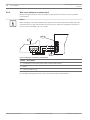
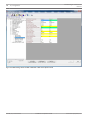
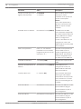
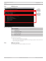
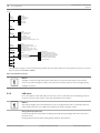
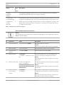
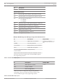
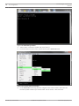
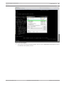
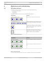
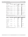
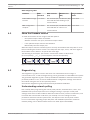
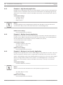
1
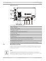
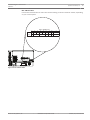
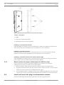
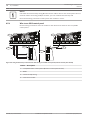
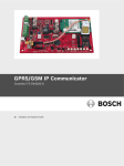
Conettix Plug-in Communicator Interface
B450
en
Installation and Operation Guide
Conettix Plug-in Communicator
Interface
Table of Contents | en
3
Table of contents
1
Safety
4
2
Introduction
5
2.1
About documentation
5
2.2
Bosch Security Systems, Inc. product manufacturing dates
5
2.3
Installation workflow
5
3
System overview
7
3.1
Module overview
7
3.2
Bus address settings
4
Installation
10
4.1
Setting the bus address
10
4.2
Insert the B44x communication module (required and available separately)
10
4.3
Mount the module in the enclosure
11
4.3.1
Mount and wire the tamper switch (option for SDI2 bus only)
12
4.4
Install and mount the plug-in communicator antenna
12
4.5
Wire to the control panel
13
4.5.1
Wire to an SDI2 control panel
14
4.5.2
Wire to an SDI control panel
15
4.5.3
Wire to an option bus control panel
16
5
Configuration
17
5.1
Plug and Play configuration
17
5.2
Configuration for SDI2 control panels
17
5.2.1
Configuring and viewing status from RPS
17
5.3
Use USB to configure the B450
22
5.3.1
Install a communication program
24
5.3.2
Log into the USB interface
25
5.3.3
USB Main menu
27
5.3.4
USB menu structure
27
5.3.5
USB menu
28
5.4
Short Message Service (SMS) configuration
32
5.4.1
Use SMS to configure the B450
32
5.5
Firmware Update page
35
6
Maintenance and troubleshooting
39
6.1
LED status indicators
39
6.2
Show the firmware version
41
6.3
Diagnostic log
41
6.4
Understanding network polling
41
6.4.1
Example 1 - High Security Application
42
6.4.2
Example 2 - Medium Security Application
42
6.4.3
Example 3 - Backup or Low Security Application
42
6.5
Control panel programming using cellular
43
7
Specifictions and certifications
44
7.1
Technical specification
44
7.2
Certifications
45
Bosch Security Systems, Inc.
8
Installation and Operation Guide
2013.09 | 02 | F.01U.282.875
4
Conettix Plug-in Communicator
Interface
en | Safety
1
Safety
ESD Precaution
Please note that while the B450 comes in a plastic case, and is protected from ESD, the plugin cellular communicator (B44x) does not. All plug-in cellular communicator components may
potentially be exposed to finger touches - therefore extra attention must be paid to ESD
(electrostatic discharge) precaution. Make sure there is no static interference when using the
board. Appropriate ESD protections must be taken and wearing electrostatic equipment is
recommended, such as anti-static wrist strap.
ESD damage can range from subtle performance degradation to complete device failure.
Precision integrated circuits may be more susceptible to damage because very small
parametric changes could cause the device not to meet its published specifications.
Warning!
!
Failure to follow these instructions can result in a failure to initiate alarm conditions. Bosch
Security Systems, Inc. is not responsible for improperly installed, tested, or maintained
devices. Follow these instructions to avoid personal injury and damage to the equipment.
Notice!
Inform the operator and the local authority having jurisdiction (AHJ) before installing the
module in an existing system.
Disconnect all power to the control panel before installing the module.
2013.09 | 02 | F.01U.282.875
Installation and Operation Guide
Bosch Security Systems, Inc.
Conettix Plug-in Communicator
Interface
Introduction | en
2
Introduction
2.1
About documentation
5
Copyright
This document is the intellectual property of Bosch Security Systems, Inc. and is protected by
copyright. All rights reserved.
Trademarks
All hardware and software product names used in this document are likely to be registered
trademarks and must be treated accordingly.
Bosch Security Systems, Inc. product manufacturing dates
2.2
Use the serial number located on the product label and refer to the Bosch Security Systems,
Inc. website at http://www.boschsecurity.com/datecodes/.
The following image shows an example of a product label and highlights where to find the
manufacturing date within the serial number.
Installation workflow
2.3
To install and configure the device, use the workflow below and follow in sequential order
from top to bottom, marking off each box as you complete a step.
Caution!
!
Always power down the control panel when connecting the B450. Power down the control
panel by unplugging the transformer and disconnecting the battery.
Plan the installation of the B450 Conettix Plug-in Communicator Interface
Unpack the device contents
Power down the system
Select the bus address value for the compatible control panel (This will automatically
configure the module to work with a compatible control panel. Refer to Setting the bus
address, page 10)
Insert the desired plug-in communicator into the B450 (Refer to Insert the B44x
communication module (required and available separately), page 10)
Mount the B450 into the enclosure (Refer to Mount the module in the enclosure, page 11)
Wire the B450 to a compatible control panel (Refer to Wire to the control panel, page 13)
Power up the system
Bosch Security Systems, Inc.
Installation and Operation Guide
2013.09 | 02 | F.01U.282.875
6
Conettix Plug-in Communicator
Interface
en | Introduction
Install a communication program (if required) (Refer to Install a communication program,
page 24)
Configure the communication module (non SDI2 control panels)
Verify LED activity
Review signal strength on the cellular communicator. Refer to your cellular communicator
Installation Guide for more information on signal strength.
Installation is complete
See also
–
Configuration, page 17
–
Maintenance and troubleshooting, page 39
2013.09 | 02 | F.01U.282.875
Installation and Operation Guide
Bosch Security Systems, Inc.
Conettix Plug-in Communicator
Interface
3
System overview | en
7
System overview
Refer to the graphic below for the complete B450 system configuration.
8
1
9
4
3
7
2
6
5
B450 system connections overview
Callout ᅳ Description
Callout ᅳ Description
1 ᅳ Compatible Bosch control panel
6 ᅳ Cellular carrier network
2 ᅳ Panel data bus (SDI2 , SDI, or Option)
7 ᅳ Internet/LAN/WAN
3 ᅳ B450
8 ᅳ Remote Programming Workstation
4 ᅳ USB direct connection for B450
9 ᅳ Bosch Conettix IP receiver (D6600,
configuration (if required)
D6100i, or D6100IPv6)
5 ᅳ B44x Plug-in Cellular Communicator
(required and available separately)
3.1
Module overview
The B450 Conettix Plug-in Communicator Interface (wired to a compatible control panel) is a
four-wire powered SDI2, or SDI device that provides two-way communication over commercial
cellular networks using a plug-in communicator.
The B450 Conettix Plug-in Communicator Interface bus address switch determines the bus
address of the device. When required, configuration of the module is managed through the
control panel, a local USB connection, or using SMS.
Bosch Security Systems, Inc.
Installation and Operation Guide
2013.09 | 02 | F.01U.282.875
8
Conettix Plug-in Communicator
Interface
en | System overview
B450 module overview
1
10
9
TX RX
8
7
6
5
4
3
2
Figure 3.1: B450 Plug-in Communicator Interface
Callout ᅳ Description
1 ᅳ Tamper switch connector
2 ᅳ Bus address switch
3 ᅳ MODE 2-pin jumper connector (for future use)
4 ᅳ Bus address label
5 ᅳ USB connector (Type A)
6 ᅳ Heartbeat LED
7 ᅳ RX LED (indicates packets received from the wireless network)
8 ᅳ TX LED (indicates packets transmitted over the wireless network)
9 ᅳ Terminal strip (to control panel)
10 ᅳ Interconnect wiring connectors (to control panel or other compatible modules)
3.2
Bus address settings
The address switch determines the bus address for the B450 Conettix Plug-in Communicator
Interface. The control panel uses the address for communications. Use a slotted screwdriver
to set the address switch.
Notice!
The B450 reads the bus address switch setting only during power up. If you change the
switch after you apply power to the module, you must cycle the power to the module in order
for the new bus address setting to be used for bus communication.
2013.09 | 02 | F.01U.282.875
Installation and Operation Guide
Bosch Security Systems, Inc.
Conettix Plug-in Communicator
Interface
System overview | en
9
Bus address label
Use the bus address label to select the desired setting on the bus address switch, depending
on your control panel.
Bus
Addr
0
cfg
1
2
1
2
SDI2
PANEL ADDRESSES
4
5
6
7
88 92
SDI
8
9
250
Option
TX RX
Figure 3.2: Bus address label
Bosch Security Systems, Inc.
Installation and Operation Guide
2013.09 | 02 | F.01U.282.875
10
Conettix Plug-in Communicator
Interface
en | Installation
4
Installation
Perform the following steps to install the B450.
Notice!
Remove all power (AC and Battery) before making any connections. Failure to do so may
result in personal injury and/or equipment damage.
4.1
Setting the bus address
The B450 Conettix Plug-in Communicator Interface address switch provides the value for the
module's address. The figure below shows the address switch setting for address 1. Refer to
the table below for panel-specific settings.
Figure 4.1: Address switch set to address 1
Control panels
USB or SMS configuration
Switch
Control panel Bus type
Function
position
bus address
0
N/A
Any
Change configuration
1
1
SDI2
Automation, RPS, or Reporting
2
2
SDI2
Automation, RPS, or Reporting
4
88
SDI1
RPS or Reporting
5
92
SDI1
RPS or Reporting
setting
B5512/B4512/
B3512,D9412GV4/
D7412GV4/D7212GV4
D9412GV4/D7412GV4/
D7212GV4
D9412GV4/D7412GV4/
D7212GV4, D9412GV3/
D7412GV3/D7212GV3
D9412GV4/D7412GV4/
D7212GV4, D9412GV3/
D7412GV3/D7212GV3
For D9412GV4/D7412GV4/D7212GV4 configurations, SDI2 bus connection is the recommended configuration
1
option, but SDI bus configuration is also supported.
Table 4.1: B450 address switch settings
4.2
Insert the B44x communication module (required and available
separately)
Insert the desired B44x communication module into the slot of the B450 until you feel the
module “click” into place.
2013.09 | 02 | F.01U.282.875
Installation and Operation Guide
Bosch Security Systems, Inc.
Conettix Plug-in Communicator
Interface
Installation | en
11
2
1
Figure 4.2: Inserting the communication module into the B450
Callout ᅳ Description
1 ᅳ B44x Plug-in Communicator module (available separately)
2 ᅳ B450 Conettix Plug-in Communicator Interface
4.3
Mount the module in the enclosure
Notice!
UL requires that for security installations, the B450 module be installed in a UL Listed
enclosure with a tamper.
Notice!
If you are not using the interconnect cable, it is recommended to wire the B450 module to
the compatible control panel via the terminal strip prior to mounting the B450 into the
enclosure. Failure to do so will complicate the mounting procedure.
Mount the B450 Conettix Plug-in Communicator Interface using the interior wall of the
enclosure’s 3-hole mounting pattern and the supplied mounting screws.
You must mount the module in the control panel enclosure, or in a UL listed enclosure.
All communicators shall be housed in tampered enclosures. If the unit is used in a commercial
burglar environment, and is enclosed in a commercial enclosure, that enclosure must be
tampered.
If the installation is a local or police station connection, then the B450 must be mounted
inside an attack resistant enclosure.
Bosch Security Systems, Inc.
Installation and Operation Guide
2013.09 | 02 | F.01U.282.875
12
Conettix Plug-in Communicator
Interface
en | Installation
Figure 4.3: Mounting the module to the exterior wall of the enclosure
Callout ᅳ Description
1 ᅳ B450
2 ᅳ Enclosure (outside wall shown)
3 ᅳ Mounting screws (3 screws included)
Installing in a control panel enclosure
Install the B450 on the inside enclosure wall that also contains the supported control panel.
The control panel powers the B450 via the terminal block or bus connection.
Installing in a separate enclosure
Install the B450 on the inside wall of a separate enclosure. The control panel in a nearby,
separate enclosure powers the B450 via the terminal block or bus connection.
Installing in a separate enclosure with separate power supply
Install the B450 on the inside wall of a separate enclosure that also has a separate external
power supply such as the B520 Auxiliary Power Supply Module.
4.3.1
Mount and wire the tamper switch (option for SDI2 bus only)
You can connect an enclosure door tamper switch for one module in an enclosure.
Installing the optional tamper switch for use with a B450:
1.
Mount the tamper switch into the enclosure’s tamper switch mounting location.
2.
Plug the tamper switch wire onto the module’s tamper switch connector. For the tamper
switch connector location, refer to Module overview, page 7.
3.
Verify the B450 module is configured with tamper enabled ON within the SDI2 supported
control panel. Tamper is automatically enabled to ON in GV4 Series v2.00 control panels.
4.4
Install and mount the plug-in communicator antenna
Perform the following steps below to install and mount the magnetic antenna.
2013.09 | 02 | F.01U.282.875
Installation and Operation Guide
Bosch Security Systems, Inc.
Conettix Plug-in Communicator
Interface
1.
Installation | en
13
Place the magnetic antenna on top of the enclosure, or vertically on another metal
surface.
Notice!
If you are experiencing a weak signal, place the antenna on top of a metal surface that has a
radius of 10.16 cm (4 in) for optimal performance.
2.
Route the antenna cable through a knock-out in the enclosure wall.
3.
Connect the antenna cable to the module.
4.
Secure the antenna cable to the inside of the enclosure.
1
2
Figure 4.4: Antenna installation
Callout ᅳ Description
1 ᅳ B44x plug-in cellular communicator antenna (routed through any knock-out)
2 ᅳB44x plug-in cellular communicator antenna cable (connected to the module)
4.5
Wire to the control panel
When you wire a B450 to an SDI, or SDI2 control panel, you can use either the module's
terminal strip labeled R, Y, G, B (PWR, A, B, COM) or the module's interconnect wiring
connectors (wire included). The figure below indicates the location of both the terminal strip
and the interconnect wiring connectors on the module.
Bosch Security Systems, Inc.
Installation and Operation Guide
2013.09 | 02 | F.01U.282.875
14
Conettix Plug-in Communicator
Interface
en | Installation
Notice!
Use either the terminal strip wiring or interconnect cable to wire to the control panel. Do not
use both. When connecting multiple modules, you can combine terminal strip and
interconnect wiring connectors to daisy-chain the modules in series.
Wire to an SDI2 control panel
4.5.1
Run the wiring connections from the module to the data bus terminals on the compatible
1k
AUX
- 12 V +
COM AUX
R Y
PWR A
G B
B COM
End of Line Resistors
1 COM 2 3 COM 4
5 COM 6
7 COM 8
1
5
7
COM
2
3
COM
4
COM
6
COM
1
ON-BOARD POINTS
Voltage Ranges
Open
3.7 - 5.0 VDC
Normal 2.0 - 3.0 VDC
Short
0.0 - 1.3 VDC
1k
AUX
- 12 V +
8
COM AUX
2
R Y
PWR A
G B
B COM
RESET
SDI2
Device Bus
R Y G B
C
OUTPUT
B
End of Line Resistors
1 COM 2 3 COM 4
5 COM 6
7 COM 8
1
5
7
COM
2
3
COM
4
COM
6
COM
C
B
OUTPUT
C
OUTPUT
B
TMPR
ON-BOARD POINTS
Voltage Ranges
Open
3.7 - 5.0 VDC
Normal 2.0 - 3.0 VDC
Short
0.0 - 1.3 VDC
C
B
OUTPUT
SDI2
Device Bus
R Y G B
TMPR
1
RESET
control panel.
8
4
3
2
R
Y
G
B
R
R
Y
Y
G
G
B
B
Figure 4.5: Using terminal strip or interconnect cable wiring on an SDI2 control panel (B Series control panel shown)
Callout ᅳ Description
1 ᅳ Compatible SDI2 control panel (B Series control panel shown)
2 ᅳ B450
3 ᅳ Terminal strip wiring
4 ᅳ Interconnect cable
2013.09 | 02 | F.01U.282.875
Installation and Operation Guide
Bosch Security Systems, Inc.
Conettix Plug-in Communicator
Interface
Installation | en
Wire to an SDI control panel
4.5.2
1
WARNING!
To prevent risk of
electric shock,
disconnect AC
power and
telephone lines
before servicing.
D9412GV3
Commercial Protected-Premises Control Panel
Refer to the D9412GV3/D7412GV3 Approved Applications Compliance Guide (P/N: F01U143069)
for System Wiring Diagram, Issue A and for compatible smoke detectors. 2-wire Compatible Identifier “A”.
Reset Pin
Disable all except Battery
Charging and Programming
POWER SUPPLY REQUIREMENTS
The Power Supply provides a maximum of 1.4 Amps for the Control Panel and all
Accessory Devices. For System Loading, refer to the D9412GV3/D7412GV3 Operation
and Installation Guide (P/N: F01U143070).
All external connections except Terminal 5 (battery positive) are inherently power
limited. Requirements for battery standby time might reduce allowable output.
PERIPHERAL DEVICE CONNECTIONS
RED
(P/N: F01U143070) for Power Requirements relating to Terminals 6 and 7 .
This equipment should be installed in accordance with the NFPA 70 (National Electrical Code) and
NFPA 72 (National Fire Alarm Code).
DATA BUS A
GREEN
DATA BUS B
Not suitable for remote station protected premises services where separate transmission circuits
are required for fire, supervisory (when applicable) and trouble signals when using D185.
11
12
13
14
15
16
Point 5 Point 6
17
18
19
20
Point 8, S3 Option
Closed = 1 kΩ EOL
Normal Operation
Open =AB-12 UL
Bell Box 220 kΩ
22
11
GREEN
12
13
Point 3 Point 4
14
15
16
Point 5 Point 6
17
18
19
YELLOW
DATA BUS A
GREEN
DATA BUS B
NFPA
Style 4.0
Signaling
Line
Circuits
COMMON
ZONEX OUT 1
ZONEX IN 1
ZONEX OUT 2 26
ZONEX POWER + 24
Point 7 Point 8
20
4
25
ZONEX IN 2 25
VOLTAGE RANGES
3.7 - 5.0 VDC Short
2.0 - 3.0 VDC
Open
Normal
Point 1 Point 2
B
POWER +
BLACK
System is intended to be checked by a Qualified Technician at least every 3 years.
The types of initiating circuits the control panel has been approved for are A, M, W, SS.
The types of signaling the control panel has been approved for are DAC, OT, NC, RevPol.
0.0 - 1.3 VDCZONEX COMMON 23
Operation Monitor LED
Pulses when Normal
Flickers when Ringing
21
Battery: Replace every 3 to
5 years with one or two Model
D126 or D1218 12 V Lead Acid
Batteries.
RED
D9412GV3 Control Panel is UL Listed For Central Station, Remote Station, Local, Auxiliary,
Proprietary, and Household Fire Alarm, and Central Station, Local, Proprietary,
Police Station Connect, Household Burglar Alarm and Encrypted Line Security when
communicating via a network.
ZONEX POWER + 24
Point 7 Point 8
(P/N: F01U143070) for Power Requirements relating to Terminals 6 and 7 .
B
Y
G
PERIPHERAL DEVICE CONNECTIONS
Not suitable for remote station protected premises services where separate transmission circuits
are required for fire, supervisory (when applicable) and trouble signals when using D185.
3
ZONEX IN 2 25
25
VOLTAGE RANGES
3.7 - 5.0 VDC Short
2.0 - 3.0 VDC
Open
Normal
G
This equipment should be installed in accordance with the NFPA 70 (National Electrical Code) and
NFPA 72 (National Fire Alarm Code).
ZONEX IN 1
ZONEX OUT 2 26
System is intended to be checked by a Qualified Technician at least every 3 years.
The types of initiating circuits the control panel has been approved for are A, M, W, SS.
The types of signaling the control panel has been approved for are DAC, OT, NC, RevPol.
Y
POWER SUPPLY REQUIREMENTS
The Power Supply provides a maximum of 1.4 Amps for the Control Panel and all
Accessory Devices. For System Loading, refer to the D9412GV3/D7412GV3 Operation
and Installation Guide (P/N: F01U143070).
All external connections except Terminal 5 (battery positive) are inherently power
limited. Requirements for battery standby time might reduce allowable output.
R
ZONEX OUT 1
D9412GV3 Control Panel is UL Listed For Central Station, Remote Station, Local, Auxiliary,
Proprietary, and Household Fire Alarm, and Central Station, Local, Proprietary,
Police Station Connect, Household Burglar Alarm and Encrypted Line Security when
communicating via a network.
Point 3 Point 4
R
Y
G
B
COMMON
BLACK
R
D9412GV3
UL Listed Local Bell
POWER +
YELLOW
NFPA
Style 4.0
Signaling
Line
Circuits
To prevent risk of
electric shock,
disconnect AC
power and
telephone lines
before servicing.
Commercial Protected-Premises Control Panel
SDI Connector
Refer to the D9412GV3/D7412GV3 Approved Applications Compliance Guide (P/N: F01U143069)
for System Wiring Diagram, Issue A and for compatible smoke detectors. 2-wire Compatible Identifier “A”.
Reset Pin
Minimum system requirements for Classification in accordance with ANSI/SIA CP-01-2007:
Disable all except Battery
UL Listed and Classified control unit Model D9412GV3, D7412GV3, or D7212GV3;
Charging and Programming
UL Listed and Classified keypad Model D1256, D1257, D1260, D1255, D1255R, or D1255RW;
2
SDI Connector
Minimum system requirements for Classification in accordance with ANSI/SIA CP-01-2007:
UL Listed and Classified control unit Model D9412GV3, D7412GV3, or D7212GV3;
UL Listed and Classified keypad Model D1256, D1257, D1260, D1255, D1255R, or D1255RW;
UL Listed Local Bell
Battery: Replace every 3 to
5 years with one or two Model
D126 or D1218 12 V Lead Acid
Batteries.
2
1
WARNING!
Point 1 Point 2
15
0.0 - 1.3 VDCZONEX COMMON 23
Point 8, S3 Option
Closed = 1 kΩ EOL
Normal Operation
Open =AB-12 UL
Bell Box 220 kΩ
Operation Monitor LED
Pulses when Normal
Flickers when Ringing
21
22
GREEN
Figure 4.6: Using terminal strip or interconnect cable wiring on an SDI control panel (GV3 Series control panel shown)
Callout ᅳ Description
1 ᅳ Compatible SDI control panel (GV3 Series control panel shown)
2 ᅳ B450
3 ᅳTerminal strip wiring
4 ᅳ Interconnect cable
Bosch Security Systems, Inc.
Installation and Operation Guide
2013.09 | 02 | F.01U.282.875
16
Conettix Plug-in Communicator
Interface
en | Installation
4.5.3
Wire to an option bus control panel
Run the wiring connections from the module to the data bus terminals on the compatible
control panel.
Notice!
When wiring the connections between the option bus terminal strip and the B450, verify the
terminal position of the colored wires as they may be in a different orientation (option bus =
R, B, G, and Y) and (B450 = R, Y, G, and B).
2
1
R
Y
R
Y
G
R
B
G
G
Y
B
B
3
Figure 4.7: Wiring to an option bus terminal strip
Callout ᅳ Description
1 ᅳ Compatible control panel (FPD-7024 control panel shown)
2 ᅳ B450
3 ᅳ Terminal strip wiring
For complete wiring instructions, refer to the control panel documentation.
2013.09 | 02 | F.01U.282.875
Installation and Operation Guide
Bosch Security Systems, Inc.
Conettix Plug-in Communicator
Interface
5
Configuration | en
17
Configuration
Notice!
Power up the system prior to the configuration workflows described in this chapter.
You can configure the B450 using one of the methods described in this section for your
control panel type.
5.1
Plug and Play configuration
When installing under the following conditions, the B450 needs no further configuration:
5.2
–
AES encryption is not required.
–
Low signal delay can be no more than 200 sec.
Configuration for SDI2 control panels
Notice!
By default, when connecting a field replacement B450 to an existing SDI2 control panel, the
control panel overrides some of the module settings such as; TCP/UDP Port Number, AES
Encryption, Tamper, Panel Programming, IPv4 DNS Server IP Address, Alternate IPv4 DNS
Server IP Address, and TCP Keep Alive Time. To keep custom module settings when you
connect a module to a configured control panel, you must disable Panel Programming prior to
connecting to the SDI2 bus. This is accomplished by using either USB, or SMS configuration.
If the SDI2 control panel is not defaulted, the panel sends the network configuration
parameters to the B450.
Address-only configuration conditions
An SDI2 control panel automatically configures a newly connected module.
1.
If the control panel is not at factory default, it transfers the configuration settings in the
control panel to the B450.
2.
Set the address switch to the correct address for the control panel (SDI2 control panels
use address 1 or 2).
3.
Program the control panel communication settings using RPS or the keypad.
The control panel stores the module settings and automatically programs a defaulted module
when connected. If manual module programming is required, use USB or SMS configuration to
set the Panel Programming parameter to Disabled before installing.
5.2.1
Configuring and viewing status from RPS
For SDI2 control panels, the networking related parameters in the Networking parameters in
RPS table can be configured through the panel or RPS. When cellular specific parameters need
to be modified, refer to the USB or SMS configuration sections within this installation and
operation guide for programming workflows and operation.
The B450 parameters within RPS can be found under the SDI2 Modules section under B42x
Ethernet Communicator. The B426 and the B450 modules share these parameters. Refer to
the illustration below for RPS menu selections.
Bosch Security Systems, Inc.
Installation and Operation Guide
2013.09 | 02 | F.01U.282.875
18
Conettix Plug-in Communicator
Interface
en | Configuration
Figure 5.1: B450 settings shown as B42x in RPS with a GV4 control panel at v1.00
2013.09 | 02 | F.01U.282.875
Installation and Operation Guide
Bosch Security Systems, Inc.
Conettix Plug-in Communicator
Interface
Configuration | en
19
Figure 5.2: B450 settings shown as B42x in RPS with a GV4 control panel at v2.00
Reference the table below for parameters configured by RPS.
Bosch Security Systems, Inc.
Installation and Operation Guide
2013.09 | 02 | F.01U.282.875
20
Conettix Plug-in Communicator
Interface
en | Configuration
Parameter
Value
Description
Tamper (for GV4 ([v1.0.x or
0 = Disabled
When enabled, allows tamper
higher] control panels)
1 = Enabled
and tamper restore
conditions to be reported to
an SDI2 control panel.
Notice!
Only control panels with a
SDI2 bus connection to the
B450 can report a tamper
condition.
IPv4 DNS Server IP Address
IPv4 address format (0.0.0.0)
The B450 uses the DNS
server addresses supplied by
the cellular network when the
Primary DNS Server address
option is configured as
0.0.0.0. If the address is not
configured as 0.0.0.0, the
B450 installs the Primary DNS
Server address.
Web access password
Enter a 4 – 10 character
The web access password is
password to access module
used to allow access to
programming Do not use the
module programming. For a
characters ; or !
B450 module, the password
controls configuration from
the USB menu and SMS text.
TCP/UDP Port Number
1 to 65535 (7700)
Sets the source port for the
B450.
Alternate IPv4 DNS Server IP
IPv4 address format (0.0.0.0)
Address
If the address is not
configured at 0.0.0.0, the
B450 installs the Alternate
DNS Server address.
TCP Keep Alive Time
0 – 255 sec (45)
This parameter determines
how long to wait between
transmissions to keep an idle
TCP connection to a remote
host from terminating due to
inactivity.
IPv4 Test Address
IPv4 address format (0.0.0.0)
The IPv4 Test Address is used
by the module to ping an
internet address as part of
the IP diagnostics.
IPv6 Test Address
IPv6 address format (0.0.0.0)
The IPv6 Test Address is used
by the module to ping an
internet address as part of
the IP diagnostics.
2013.09 | 02 | F.01U.282.875
Installation and Operation Guide
Bosch Security Systems, Inc.
Conettix Plug-in Communicator
Interface
Configuration | en
21
Table 5.1: B450 networking parameters configurable in RPS
Notice!
If you are using a GV4 version 1.00 control panel, select “B420 Ethernet Communicator”
within RPS. If you are using a GV4 v2.00 control panel or higher, or a B Series control panel,
select ”B426 Ethernet Communicator” within RPS.
Information about the B450 such as it's Status, IP Address, Bus Voltage and the assigned
phone number of the plug-in module can be found on the RPS Diagnostics screen for the B42X
module per figure 5.2. The plug-in communicator's phone number is displayed in the
"Hostname" field. Refer to the illustration below.
Figure 5.3: B450 status shown as Ethernet Communicator in RPS Diagnostics with GV4 version 1.00
Bosch Security Systems, Inc.
Installation and Operation Guide
2013.09 | 02 | F.01U.282.875
22
Conettix Plug-in Communicator
Interface
en | Configuration
Figure 5.4: B450 status as shown as Ethernet Communicator in RPS Diagnostics with GV4 version 2.00
5.3
Use USB to configure the B450
You can use a USB connection from a laptop PC to the B450 to configure the B450 on-site.
The supported USB cable used to establish connection is a Type A to A, male-to-male cable.
Notice!
USB connection via the USB cable is used for temporary configuration programming only.
Before you can access the USB user interface, you must install the RBUS1CP.inf file, and USB
driver on the target PC or laptop. The RBUS1CP.inf file and USB driver are available on the
supplied CD‑ROM. You need to install this file only once on the target PC or laptop.
If the B450 CD-ROM is not available:
1.
From your Internet browser, go to: http://www.boschsecurity.com to open the Bosch
Web site.
2.
Select the web site for your region and country.
3.
In the Online Catalogs section on the left, click the Intrusion Alarm Systems link.
4.
Under the Intrusion Alarm Systems Products heading, scroll to the Conettix Information Transport Solutions section. Click the Show product section link.
5.
Click the Conettix IP link.
6.
Scroll to the B450 Plug-in Communicator Interface section. Click the section title to
open the product page.
7.
Under the product image, click the Software tab.
8.
Click OK to accept the license agreement.
2013.09 | 02 | F.01U.282.875
Installation and Operation Guide
Bosch Security Systems, Inc.
Conettix Plug-in Communicator
Interface
9.
Configuration | en
23
To the right of the B450, click on the language link (for example, en).
The File Download dialog box opens.
10. Click Save to save the file to the target PC or laptop. Perform this task to download both
the USB driver file, and the RBUS1CP.inf file.
11. Supply power to the B450.
12. Connect the B450 to the target PC or laptop, using a USB Type A to A cable. A New
Hardware Found window appears on the computer.
13. Install the RBUS1CP.inf file onto your PC or laptop. Verify through the device manager
that the appropriate .inf installs properly, and is listed under the Ports (COMM & LPT)
section. The correct .inf file is B450 Config Interface.
Figure 5.5: RBUS1CP.inf installed inside Device Manager
14. Install a communication program to configure the B450.
Bosch Security Systems, Inc.
Installation and Operation Guide
2013.09 | 02 | F.01U.282.875
24
Conettix Plug-in Communicator
Interface
en | Configuration
5.3.1
Install a communication program
To use USB connection from a computer to the B450 to configure the B450, you must use a
communication program.
–
Windows XP. The Microsoft Windows XP installation automatically installs HyperTerminal,
a Microsoft communication program, when Windows installs. If HyperTerminal is not
installed, install it from the Windows XP installation disc, or install Tera Term from the
B450 CD.
–
Windows Vista and Windows 7/8 installations no longer include a communication
program when the operating system installs. Install Tera Term from the B450 CD.
Install the communication program that supports your configuration (Hyper Terminal or Tera
Term), depending on your laptop or PC’s operating system.
Notice!
Tera Term is preferred in all applications as its operation is understood by Bosch Technical
Support if assistance is required.
Installing Tera Term
When you perform the Tera Term installation, follow the prompts in the installation wizard,
but on the Select Components page of the wizard, select Compact installation from the dropdown list. Refer to the figure below.
Figure 5.6: Setup - Tera Term wizard's Select Components window
Tera Term version interface
After installing the latest Tera Term version, double-click on Tera Term to launch the program.
The Tera Term window opens.
2013.09 | 02 | F.01U.282.875
Installation and Operation Guide
Bosch Security Systems, Inc.
Conettix Plug-in Communicator
Interface
Configuration | en
25
Figure 5.7: Tera Term Pro version 4.77 window shown
5.3.2
Log into the USB interface
Notice!
To allow for USB configuration, address switch must be set to 0. Powering down the module
after changing the bus address switch for programming is not required.
1.
Ensure that the USB-Type A male-to-male cable is connected to the B450 and the target
2.
From Windows, start a terminal session by launching Hyper Terminal on Windows XP or
PC or laptop.
earlier, or launching Tera Term on Windows Vista/Windows 7/Windows 8.
3.
Set up a connection on the new virtual serial COM port (for example, Port: COM7: B450
[COM7]). If the B450 is not connected to the computer, or the USB driver is not installed,
the B450 does not appear in the list.
4.
After the connection is established, press [Enter].
The B450 USB login window opens.
Bosch Security Systems, Inc.
Installation and Operation Guide
2013.09 | 02 | F.01U.282.875
26
Conettix Plug-in Communicator
Interface
en | Configuration
Figure 5.8: B450 USB login window
5.
Enter the password to log on. The default password is B450.
The user interface allows three attempts to enter the password correctly. After three
failed attempts, the B450 shows a Too many attempts error message, and the USB
interface enters into an idle state for 30 sec. Repeat Steps 3 through 6. at the conclusion
of 30 sec.
6.
2013.09 | 02 | F.01U.282.875
Press [Enter] to continue. The USB main menu opens.
Installation and Operation Guide
Bosch Security Systems, Inc.
Conettix Plug-in Communicator
Interface
5.3.3
Configuration | en
27
USB Main menu
1
2
3
4
Figure 5.9: USB Main Menu
Callout Description
1
Installed device
2
Current device status
3
Current access level
4
Main menu options
The USB main menu appears:
5.3.4
–
after a user enters a password successfully
–
every time the user presses [Enter] without first selecting an option from the main screen
–
upon returning from a sub-menu.
USB menu structure
The following illustration depicts the B450 menu structure.
Bosch Security Systems, Inc.
Installation and Operation Guide
2013.09 | 02 | F.01U.282.875
28
Conettix Plug-in Communicator
Interface
en | Configuration
Main Menu
0 Main Menu
Status
(Starts with
Basic Status)
1
1 Basic Status Menu
2 Advanced Status Menu
3 Reset Status
4 Signal Strength
5 Product Versions
Change
Passcode
2
Basic
Configuration
3
0 Main Menu
1 TCP/UDP Port Number: 7700
2 AES Encryption: Disabled
3 Tamper: Disabled
4 Panel Programming: Enabled
5 SMS Configuration: Enabled
6 Reporting Delay for Low Signal Strength (sec.): 1800
Advanced
Configuration
4
Reset to
Factory Defaults
5
0 Main Menu
1 IPv4 DNS Server IP Address: 0.0.0.0
2 Alternate IPv4 DNS Server IP Address: 0.0.0.0
3 Modem Reset Count: 5
4 Reporting Delay for No Towers (sec.): 1800
5 Reporting Delay for Single Tower (sec.): Disabled
6 TCP Keep Alive Time (sec.): 45
0 Main Menu
Diagnostic Log*
6
Firmware
Update
1 Modify Diagnostic Settings
2 Re-Print all Console Messages
3 Enable Live Console Messages
0 Diagnostic Log Menu
1 Cellular Modem Verbose Mode: Disabled
2 Bus Communications Verbose Mode: Disabled
3 Network Communications Verbose Mode: Disabled
4 Network Operations Verbose Mode: Disabled
5 Module Operations Verbose Mode: Disabled
6 Disable All Verbose Modes
7
Save and Exit
8
Exit
9
* The Diagnostic Log option is used in troubleshooting communication issues with the B450. Use of the Diagnostic Log option is to be used
only at the direction of TECHNICAL SUPPORT.
Figure 5.10: USB menu structure
Notice!
Changes or edits to programming are discarded if you select the Exit option, and exit the
menu. If you make changes or edits, select the Save and Exit option to ensure programming
changes are saved.
5.3.5
USB menu
For a description of the USB option menu items, refer to the tables in the following sections.
To go to a specific menu option, enter the appropriate menu option.
Notice!
Any and all changes are lost and will have to be re-programmed if there is inactivity (last key
press) within the Tera Term USB session within a 5-minute duration of time.
Using the Escape (Esc) key
Press the Escape (Esc) key without making any programming changes will return you to the
previous menu.
Pressing the Escape key after entering data will clear data entered.
2013.09 | 02 | F.01U.282.875
Installation and Operation Guide
Bosch Security Systems, Inc.
Conettix Plug-in Communicator
Interface
Option
Press
Configuration | en
29
Description
to
Select
1. Status (Starts
1
To access and view the link, modem, and bus status
with Basic
For additional menu descriptions, refer to the USB Status sub-menu parameters table
Status)
below for more information.
2. Change
2
Passcode
To change the login passcode, enter the new passcode twice. The second entry
confirms the new passcode.
Passcodes must be 4-10 characters long, and are case-sensitive.
0-9, A-Z, a-z, and special characters are allowed.
Notice!
If SMS configuration is used, do not use semicolon (;) or exclaimation mark (!) as
part of the passcode.
3. Basic
3
Configuration
Select to program Basic Configuration options. Press 0 to return to the Main menu.
To change a basic parameter, select the option to change, and then enter in the new
value.
4. Advanced
4
Configuration
Select to program Advanced Configuration options. Press 0 to return to the Main
menu.
To change an advanced parameter, select the option to change, and then enter in the
new value.
5. Reset to
5
Factory Defaults
Select to reset all factory default values. All fields are cleared and the factory default
values are restored.
Notice!
A non-defaulted SDI2 control panel will overwrite the default settings if connected to
the defaulted module.
6. Diagnostic Log 6
Select to review the Diagnostic log.
7. Firmware
Select this option to update the firmware in the B450.
7
Update
Notice!
Download your update file from the Bosch website prior to performing an update.
For more information on Firmware update workflows, refer to Firmware Update page,
page 35.
8. Save and Exit
8
Press 8 to save changes and exit the menu.
A message of Changes saved displays in the window. This occurs if changes have
been made, otherwise a message of No changes made displays in the window.
9. Exit
9
Select to exit the menu and log out. You must enter the passcode to log back in.
Notice!
If configuration changes have been made, and the Exit option is selected, those
changes are discarded.
Table 5.2: USB Main Menu parameters
Status sub-menu parameters
For a description of the Status sub-menu parameters (Reset Status, Signal Strength, and
Product Versions), refer to the table below.
To go to a specific menu option, enter the appropriate menu item number to enter that item.
Bosch Security Systems, Inc.
Installation and Operation Guide
2013.09 | 02 | F.01U.282.875
30
Conettix Plug-in Communicator
Interface
en | Configuration
Option
Press
Description
to
Select
3. Reset Status
3
The status displays show several items that are counts of activities, such as UDP
packets transmitted. When reset status is selected, all counts are returned to zero.
This is not required for normal operation.
4. Signal
4
Strength
The current signal strength records every 15 minutes for up to 48 hours worth of
data. When signal strength is selected, up to 192 values are displayed representing
the signal strength values over the last 48 hours. If the B450 has been powered up
less than 48 hours, the list shows only the samples taken so far.
4. Product
5
Versions
This option displays the software version of all entities in the B450. The following list
is an example of the versions displayed:
*** Product Versions ***
B450 Application: V 3.01.002
B450 Boot Loader: V 1.05.001
RTOS: V 3.03.500
Fusion Stack: V 8.07.3703
Cellular Manager: V 1.117.442
UPKI Encryption: V 3.03.002
AES Lib: V 01.00.000
Modem Firmware: V 15.00.021
Table 5.3: Status sub-menu parameters
Diagnostic Log sub-menu parameters
For a description of the Diagnostic Log sub-menu parameters (Modify Diagnostic Settings, Reprint All Console Messages, and Enable Console Messages), refer to the table below.
Notice!
The Diagnostic Log option is used in troubleshooting communication issues with the B450 .
Use of the Diagnostic Log option is to be used only at the direction of TECHNICAL SUPPORT.
Refer to Diagnostic log, page 41 for more information.
To go to a specific menu option, enter the appropriate menu item number to enter that item.
2013.09 | 02 | F.01U.282.875
Installation and Operation Guide
Bosch Security Systems, Inc.
Conettix Plug-in Communicator
Interface
Option
Press
Configuration | en
31
Description
to
Select
1. Modify
1
Diagnostic
The Diagnostic logging is intended for use only under Bosch direction. Diagnostic
settings determine which types of messages to display.
Settings
2. Re-print All
2
Console Message
3. Enable Live
The Re-print all option prints any diagnostic messages that have already occurred and
are stored in the B450’s buffer. This can print what just happened if an issue occurs.
3
Enable live console messages provides real time output of diagnostic messages. This
Console
allows the PC running TeraTerm to log what is occurring in the module and can log
Messages
for longer periods of time.
Table 5.4: Diagnostic Log sub-menu parameters
SMS and USB configuration parameters
Notice!
The table below shows all parameters available through SMS or USB configuration. Values in
bold are default settings.
ID
Parameter
Values
Description
1
Current Password
4 to 10 characters (B450)
Mandatory and case sensitive.
Notice!
Make sure you record and record your password.
2
New Password
4 to 10 characters
New password, as desired. Case sensitive.
13
TCP/UDP Port
1 to 65535 (7700)
Sets the source port for the B450.
0 = Disabled
Security encryption on or off. The setting must
1 = 128 bit, 2 = 192 bit, 3 = 256
match the encryption settings in the receiver.
bit
Notice!
Number
15
AES Encryption
This setting applies to SDI, and GV4 v1.0.x control
panels only.
16
AES Encryption Key
32, 48, or 64 digits max.
The AES Encryption Key must match the encryption
0-9, A-F, a-f allowed
key in the receiver.
01020304050607080910111213 Notice!
14151617181920212223242526 This setting applies to SDI, and GV4 v1.0.x control
19
272829303132
panels only.
Tamper (for GV4
0 = Disabled
When enabled, allows tamper and tamper restore
v1.0.x control
1 = Enabled
conditions to be reported to an SDI2 control panel.
panels)
Notice!
Only control panels with a SDI2 bus connection to
the B450 can report a tamper condition.
Bosch Security Systems, Inc.
Installation and Operation Guide
2013.09 | 02 | F.01U.282.875
32
Conettix Plug-in Communicator
Interface
en | Configuration
ID
Parameter
Values
Description
20
SMS Configuration
0 = Disabled
Allows the B450 to be configured via SMS
1 = Enabled
configuration.
IPv4 address format (0.0.0.0)
The B450 uses the DNS server addresses supplied
65
IPv4 DNS Server IP
Address
by the cellular network when the Primary DNS
Server address option is configured as 0.0.0.0. If
the address is not configured as 0.0.0.0, the B450
installs the Primary DNS Server address.
66
Alternate IPv4 DNS
IPv4 address format (0.0.0.0)
Server IP Address
67
If the address is not configured at 0.0.0.0, the B450
installs the Alternate DNS Server address.
Panel Programming
0 = Disabled
Select to enable or disable control panel
Enabled
1 = Enabled
programming. This enables/disabled configuration
of the B450 by the control panel.
68
Reporting Delay for
0 – 3600 sec. (1800)
Sets the duration of time when the B450’s signal
Low Signal
strength is measured. The value selected
Strength
determines how long the signal strength must be at
a low condition before reporting as low, or how
long the signal strength must be normal before
reporting as normal.
69
Reporting Delay for
0 – 3600 sec. (1800)
No Towers
Amount of delay before the module reports a
trouble for not being able to receive signals from a
cell tower.
70
Reporting Delay for
0 – 3600 sec. (0)
Single Tower
Amount of time delay before module reports a
trouble due to getting signals from only one tower
instead of multiple towers.
71
Modem Reset
0 – 99 communication attempts
This parameter determines how many times a
Count
(5)
packet of data must be sent without a reply before
the cell module modem is reset to attempt
restoring communications.
72
TCP Keep Alive
0 – 255 sec (45)
This parameter determines how long to wait
Time
between transmissions to keep an idle TCP
connection to a remote host from terminating due
to inactivity.
Table 5.5: SMS and USB configuration parameters
5.4
Short Message Service (SMS) configuration
The B450 supports configuration by SMS connection. The Short Message Service feature
allows an installer to configure the B450 through the use of a mobile phone, or any other
service that sends compatible SMS text messages.
5.4.1
Use SMS to configure the B450
The SMS string follows a specific format. If the configuration message exceeds 160
characters, you must send multiple messages. Refer to Compose the Configuration SMS for
more details.
When the B450 receives the final valid part of an SMS message, it accepts the configuration.
2013.09 | 02 | F.01U.282.875
Installation and Operation Guide
Bosch Security Systems, Inc.
Conettix Plug-in Communicator
Interface
Configuration | en
33
Notice!
To allow the receipt of SMS data, the bus address switch must be set at position 0. Refer to
the tables in this section for LED activity.
If the bus address switch is not set to 0, incoming SMS data is discarded.
Enter CONFIG MODE
Ensure that the bus address switch is set to 0.
Compose the Configuration SMS
Use the appropriate SMS template for the selected mode of operation, and compose the
configuration SMS message on your mobile phone. SMS can contain only 160 characters.
Refer to Multiple SMS Messages (for Messages Longer than 160 Characters) for instructions
for sending a multiple SMS configuration.
The templates below contain only the essential configuration IDs. For additional configuration
IDs, refer to the SMS configuration parameters.
Notice!
Separate each ID or value pair with a semi-colon ; (for example, %1;1=B450;19=1;!). To allow
spanning of configuration across multiple messages, each SMS starts with the sequence
number followed by the command line separator.
Use the ! character to signal the end of the configuration data. Refer to your cellular phone’s
documentation for available characters. You must include the current SMS configuration
passcode in the SMS text message to allow the module to save the new configuration data.
SMS configuration parameters
ID
Description
1=
Current passcode (4 to 10 characters); default = B450
2=
New passcode (4 to 10 characters)
Basic parameters
13=
TCP/UDP port number: 7700 (1 to 65535)
15=
AES encryption
16=
–
0 = disable
–
1 = 128 bit
–
2 = 192 bit
–
3 = 256 bit
AES encryption key (0 to 9, A-F, a-f, based on key size,
none, 32, 48, or 64 digits)
19=
20=
Bosch Security Systems, Inc.
Tamper (V1.0.x control panels on SDI2 bus)
–
0 = disable
–
1 = enabled
SMS configuration
–
0 = disabled
–
1 = enabled
Installation and Operation Guide
2013.09 | 02 | F.01U.282.875
34
Conettix Plug-in Communicator
Interface
en | Configuration
ID
Description
Advanced parameters
65=
Primary DNS server address (IPv4 address format)
66=
Alternate DNS server address (IPv4 address format)
67=
Panel programming enabled
–
0 = disabled
–
1 = enabled
68=
Reporting delay for low signal strength (0 - 3600 sec)
69=
Reporting delay for no towers (0 - 3600 sec)
70=
Reporting delay for single tower (0 - 3600 sec)
71=
Modem reset count (0 – 99)
72=
TCP keep alive time (0 – 255 sec)
Table 5.6: SMS configuration parameters
Multiple SMS Messages (for Messages Longer than 160 Characters)
ID
Description
Sample SMS1
%1;
SMS sequence number 1
%1;1=B450;2=secret123;15=3;
16=010203040506070809101112131
41516;
1=B450;
Current password
2=secret123;
New password (case sensitive)
15=3;
Enable AES encryption
16=01020304050607080910 Sample AES key
111213141516;
As you enter in the various ID’s into your cell phone, do not
1
press the return key. Doing so will cause the B450 to ignore
the programming request.
Table 5.7: Double SMS example, part 1
ID
Description
Sample SMS2
%2;
SMS sequence number
%2;19=1;!
19=1;
Tamper enabled
!
End of configuration
When you end the configuration programming with the
2
exclamation mark, do not enter any values. Doing so may
cause the B450 to ignore the programming request.
Table 5.8: Double SMS example, part 2
2013.09 | 02 | F.01U.282.875
Installation and Operation Guide
Bosch Security Systems, Inc.
Conettix Plug-in Communicator
Interface
Configuration | en
35
Send the Configuration SMS
1. Send the configuration SMS to the B44x module’s phone number. The transmission might
take several minutes. Because the bus address switch is set to 0, the B450 waits for an
SMS until a message is received.
2.
Observe the LEDs on the B450. When the Transmit (TX) and Receive (RX) LEDs will flash
in unison at a 1 second interval indicating a successful SMS was received. If the SMS was
received but was not valid the Transmit (TX) and Receive (RX) LEDs will alternate flashing
at 1/2 second interval. Both flashing patterns will continue until the bus address switch is
moved from position "0.”
Notice!
If the LEDs indicate an invalid SMS, repeat the steps in Enter CONFIG MODE.
Refer to the tables in Maintenance and troubleshooting, page 39 section for more information
on LED descriptions. Ensure that your configuration SMS contains the correct information, as
well as sending the SMS to the correct phone number for the module, or use the USB
connection to configure the B450
Exit from CONFIG MODE
1. Change the bus address switch to the desired value, depending on the supported control
panel. Changes to the B450 configuration are accepted.
2.
5.5
Check the signal strength and Heartbeat LED for status.
Firmware Update page
Firmware updates are performed through the USB interface via a communication program
such as Hyper Terminal or Tera Term.
Notice!
When performing a firmware update, verify that the update software file to be downloaded is
the most current software update version. No changes to the firmware occur if the firmware
update version is the same version as the current version installed on the B450.
1.
Ensure that the USB cable is connected to the B450 and the target PC or laptop.
2.
From Windows, start a terminal session by launching Hyper Terminal on Windows XP or
earlier, or launching Tera Term on Windows Vista/Windows 7/Windows 8.
3.
Log into the USB interface as described in Log into the USB interface, page 25, starting at
step 3, and continuing through to step 6. The B450 USB login window appears, listing the
current software version and build.
Bosch Security Systems, Inc.
Installation and Operation Guide
2013.09 | 02 | F.01U.282.875
36
Conettix Plug-in Communicator
Interface
en | Configuration
Figure 5.11: B450 USB login window
4.
Select option 7 Firmware Update and press [Enter].
5.
From the Tera Term main menu, select File>Transfer>XMODEM>Send.
Figure 5.12: Firmware update send window
6.
In the XMODEM Send dialog window, navigate to the folder location and select the
firmware update software you downloaded. The file ends in *.kfw extension.
2013.09 | 02 | F.01U.282.875
Installation and Operation Guide
Bosch Security Systems, Inc.
Conettix Plug-in Communicator
Interface
Configuration | en
37
Figure 5.13: File navigation
7.
Click Open to start the firmware update. The Tera Term: XMODEM Send dialog box opens
and indicates the update process.
Bosch Security Systems, Inc.
Installation and Operation Guide
2013.09 | 02 | F.01U.282.875
38
Conettix Plug-in Communicator
Interface
en | Configuration
Figure 5.14: Tera Term XMODEM Send dialog box
8.
When the file transfer completes, the Tera Term: XMODEM Send dialog box closes
automatically. Within the Tera Term window an updating to firmware version “x.xx.xxx”
message displays, and the B450 automatically reboots.
9.
Close the Tera Term session, and re-launch Tera Term.
10. Log back into Tera Term as described previously to re-establish communication from your
laptop, to the B450.
Communication between the control panel and B450 is restored.
2013.09 | 02 | F.01U.282.875
Installation and Operation Guide
Bosch Security Systems, Inc.
Conettix Plug-in Communicator
Interface
Maintenance and troubleshooting | en
6
Maintenance and troubleshooting
6.1
LED status indicators
39
The B450 includes the following on-board LEDs to assist with troubleshooting:
–
Heartbeat (system status).
–
RX (receive).
–
TX (transmit).
The plug-in module also includes LEDs for troubleshooting and status.
Flash pattern
Function
Flashes once every 1 sec
Normal state. Indicates normal operation.
3 quick flashes every 1 sec
Communication error state. Indicates a bus
communication error with the control panel.
On Steady
Trouble state. Indicates a trouble condition
exists. Examine the other LEDs to determine
the trouble condition.
Off
LED trouble state. Indicates the module is
not powered up, or there is a failure in the
module. Check for proper installation.
Table 6.1: Heartbeat LED descriptions
Flash pattern
Function
RX (Receive) Flashing
Occurs every time a packet is received on-air.
TX (Transmit) Flashing
Occurs every time a packet is transmitted onair.
Table 6.2: RX and TX LED descriptions
Plug-in communicator LEDs
For communicator LED information, refer to the compatible communicator documentation.
Bosch Security Systems, Inc.
Installation and Operation Guide
2013.09 | 02 | F.01U.282.875
40
Conettix Plug-in Communicator
Interface
en | Maintenance and troubleshooting
Trouble condition LEDs
Condition
B450 Heartbeat
B450 Transmit
B450 Receive
Plug-in module
(TX)
(RX)
status
Module tamper
Plug-in module
Not indicated
On Steady
Off
Blink 1
N/A
On Steady
Off
Blink 3
Off
Low bus voltage
On Steady
Off
Blink 4
Off
Cellular modem
On Steady
Off
Blink 5
Off
On Steady
Off
Blink 6
1 Hz Heartbeat
On Steady
Off
Blink 7
On Steady
B450 Transmit
B450 Receive
Plug-in module
(TX)
(RX)
status
missing
Plug-in module
not recognized
failure
Switch position
trouble
Configuration
failure
Table 6.3: B450 module related trouble conditions
Condition
B450 Heartbeat
No IP address
On Steady
Off
Off
Blink 2
Cellular number
On Steady
Off
Off
Blink 3
On Steady
Off
Off
Blink 4
On Steady
Off
Off
On Steady
On Steady
Off
Off
On Steady
On Steady
On Steady
Off
not activated
Not enough
towers (single
tower)
Low signal
strength
No towers
Detecting plug-in On Steady
module type
Table 6.4: Plug-in module related trouble conditions
2013.09 | 02 | F.01U.282.875
Installation and Operation Guide
Bosch Security Systems, Inc.
Conettix Plug-in Communicator
Interface
Maintenance and troubleshooting | en
41
SMS configuring LEDs
Condition
B450
B450 Transmit
B450 Receive
Plug-in module
Heartbeat
(TX)
(RX)
status
Invalid SMS message 1 sec flash
The Transmit (TX) and Receive (RX)
received
LEDs will alternate flashing at 1/2
1 sec flash
second interval
SMS configuration
complete
1 sec flash
The Transmit (TX) and Receive (RX)
1 sec flash
LEDs will flash in unison at a 1
second interval
6.2
Show the firmware version
To show the firmware version using an LED flash pattern:
–
the optional tamper switch is installed:
With the enclosure door open, activate the tamper switch.
–
If the optional tamper switch is NOT installed:
Momentarily short the tamper pins.
When the tamper switch is activated (open to closed), the heartbeat LED stays OFF for 3 sec
before indicating the firmware version. The LED pulses the major, minor, and micro digits of
the firmware version, with a 1 sec pause after each digit.
The following is an example: The version 1.4.3 would be shown as LED flashes:
[3 second pause] *__****__*** [3 second pause, then normal operation].
Figure 6.1: Firmware LED flash patterns example
6.3
Diagnostic log
The Diagnostic Log option is used in the event of an intermittent service outage, or
communication error, in which a diagnostic log can be generated from the B450 menu options.
The generated diagnostic log file is used by TECHNICAL SUPPORT to determine how often a
persistent problem occurs, as well as detailed network configuration settings associated to
the module during the time of the reported problem.
Generate the diagnostic log only when directed by TECHNICAL SUPPORT.
6.4
Understanding network polling
Plan carefully when programming the control panel poll time, ACK wait times, retries, and
D6x00 Receiver poll and supervision time. Having the wrong or improper control panel
settings could cause trouble conditions when the network carrier performs maintenance, and
increased data volumes that could effect your monthly cost. Your settings for these
parameters determine how the system works, but depend on the security level needed.
For more information regarding proper data plans and installation parameters related to
network polling, refer to Bosch Cellular Service User Guide (P/N: F01U273558).
Bosch Security Systems, Inc.
Installation and Operation Guide
2013.09 | 02 | F.01U.282.875
42
Conettix Plug-in Communicator
Interface
en | Maintenance and troubleshooting
6.4.1
Example 1 - High Security Application
Polling times are typically less than 20 min. Path integrity is critical, and short interruptions in
network service are indicated at the premise and central station. The following High Security
Application recommendation assumes the B450 is the primary communication device with no
backup.
Control panel settings
–
Poll Rate: 240 sec
–
ACK Wait: 10 sec
–
Retry Count: 5
Notice!
For high supervision rates on high latency networks, the ACK Wait can be increased to 15
seconds with a Retry Count of 3 to allow extra time for acknowledgements.
D6x00 receiver settings
–
Poll rate-supervision time: 300 sec
6.4.2
Example 2 - Medium Security Application
Polling times are typically 1 to 4 hours. Path integrity is important, and short interruptions in
network service might be indicated at the premise and central station. The following Medium
Security Application recommendation assumes the B450 is the primary
communication device with no backup.
Control panel settings
–
Poll Rate: 12600 sec (3.5 hours)
–
ACK Wait: 300 sec (5 min)
–
Retry Count: 5
D6x00 receiver settings
–
Poll rate-supervision time: 4 hours
6.4.3
Example 3 - Backup or Low Security Application
Polling times are typically 12 to 24 hours. Path integrity is only tested once or twice a day, and
short interruptions in network service are generally not indicated at the premise and central
station. Using settings similar to the following allows the system to recover from short outages
without causing trouble conditions at the premise. The following Backup or Low Security
Application recommendation assumes the B450 is the primary or backup communication
device.
Control panel settings
–
Poll Rate: 65535 sec (24 hours)
Notice!
65535 is used in the GV3 and GV4 Series control panels to program 24 hours.
–
ACK Wait: 300 sec (5 min)
–
Retry Count: 10
D6x00 receiver settings
–
Poll rate-supervision time: 25 hours
2013.09 | 02 | F.01U.282.875
Installation and Operation Guide
Bosch Security Systems, Inc.
Conettix Plug-in Communicator
Interface
6.5
Maintenance and troubleshooting | en
43
Control panel programming using cellular
For more information regarding proper planning and installation parameters related to VPN
setup for control panel programming, refer to Bosch Cellular Service User Guide (P/N:
F01U273558).
Bosch Security Systems, Inc.
Installation and Operation Guide
2013.09 | 02 | F.01U.282.875
44
Conettix Plug-in Communicator
Interface
en | Specifictions and certifications
7
Specifictions and certifications
7.1
Technical specification
Environmental considerations
Relative humidity
Up to 93% non-condensing
Temperature (operating)
0゚ - +49゚C (+32゚ - 120゚F)
Properties
Dimensions (HxWxD)
79 mm x 128 mm x 38 mm (3.11 in x 5.03 in x 1.50 in)
Power requirements
Current
Standby: B450 with B440/B441 = 60 mA
Alarm: B450 with B440/B441 = 180 mA
Voltage
(B450 bus operation): 12 VDC nominal
Wiring
Data bus wire gauge
12 AWG to 22 AWG
Data bus wire length
Maximum distance – Wire size :
22 AWG (0.65 mm) --> 12 m (40 ft)
18 AWG (1.0 mm) --> 30 m (100 ft)
16 AWG (1.3 mm) --> 48 m (158 ft)
12 AWG (2.0 mm) --> 122 m (400 ft)
Using a separate UL listed power supply, such as the B520
Auxiliary Power Supply Module, connected to the B450 within
the specification listed above, the wire distance can be
extended up to 300 m (1000 ft)
USB cable
Type A male-to-male
Compatible enclosures
B10 ᅳ 35.6 cm x 31.8 cm x 7.6 cm (14 in x 12.5 in x 3 in)
B11 ᅳ 27.8 cm x 25.9 cm x 8.32 cm (10.9 in x 10.2 in x 3.3 in)
D8103 ᅳ 41 cm x 41 cm x 9 cm (16 in x 16 in x 3.5 in)
D203 ᅳ 19.68 cm x 13.05 cm x 6.35 cm (7.75 in x 5.14 in x 2.50 in)
Notice!
Temporary loss of communication may be caused by static when using anyone of the above
enclosures.
2013.09 | 02 | F.01U.282.875
Installation and Operation Guide
Bosch Security Systems, Inc.
Conettix Plug-in Communicator
Interface
Specifictions and certifications | en
45
Compatible control panels
B5512/B4512/B3512
D9412GV4/D7412GV4 v2.00
D9412GV4/D7412GV4 v1.00.0xx
D9412GV3/D7412GV3/D7212GV3
FPD-7024 (v1.03+)
7.2
Certifications
Region
Certification
US
NIST FIPS 197
FCC Part 15 Class B
UL 365 – Police Station Connected Burglar Alarm
Units and Systems
UL 636 – Hold Up Alarm Units and Systems
UL 864 – Control Units and Accessories for Fire
Alarm Systems
UL 985 – Household Fire Warning System Units
UL 1023 – Household Burglar Alarm System Units
UL 1076 – Proprietary Burglar Alarm Units and
Systems
UL 1610 – Central Station Burglar Alarm Units
SIA CP-01:2010 False Alarm Reduction
Bosch Security Systems, Inc.
Installation and Operation Guide
2013.09 | 02 | F.01U.282.875
Bosch Security Systems, Inc.
130 Perinton Parkway
Fairport, NY 14450
USA
www.boschsecurity.com
© Bosch Security Systems, Inc., 2013