1
OB319--1.qxp
03.12.3 0:54 PM
Page 1
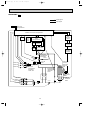
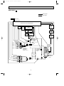
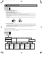
SPLIT-TYPE, HEAT PUMP AIR CONDITIONERS
HFC
No. OB319
utilized
SERVICE MANUAL
R410A
Inverter-controlled multi system
Models
MXZ-A18WV MXZ-A26WV MXZ-A32WV -
E1
E1
E1
CONTENTS
Indication of model name
MXZ-A18WV -
E1
1. TECHNICAL CHANGES ····································3
2. PART NAMES AND FUNCTIONS······················7
3. INDOOR/OUTDOOR
CORRESPONDENCE TABLE ···························7
4. INDOOR UNITS COMBINATION ·····················10
5. SPECIFICATION···············································21
6. NOISE CRITERIA CURVES ·····························23
7. OUTLINES AND DIMENSIONS ·······················24
8. WIRING DIAGRAM ··········································27
9. REFRIGERANT SYSTEM DIAGRAM ··············30
10. PERFORMANCE CURVES ······························33
11. MICROPROCESSOR CONTROL·····················47
12. TROUBLESHOOTING······································52
13. DISASSEMBLY INSTRUCTIONS·····················71
14. PARTS LIST······················································78
15. OPTIONAL PARTS···········································83
NOTE:
•The description for MXZ-A18WV- E1 has been transferred here from service manual OB307 REVISED
EDITION-A.
•SPECIFICATION, PERFORMANCE CURVES and PARTS LIST of MXZ-A18WV- E1 have been partially
modified.
•This service manual describes technical data of outdoor units.
As for indoor units, refer to the service manual OB307 REVISED EDITION-A, OB321, OB327 or B329.
OB319--1.qxp
03.12.3 0:54 PM
Page 2
OB319--1.qxp
03.12.3 0:54 PM
1
Page 3
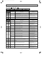
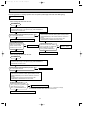
TECHNICAL CHANGES
MXZ-18TV - E2 ➔ MXZ-A18WV - E1
1. Outdoor model has changed.
2. Refrigerant has changed. (R22➔R410A)
MXZ-24UV - E2 ➔MXZ-A26WV - E1
1.
2.
3.
4.
5.
6.
7.
Cooling capacity has become larger. (7.1kW➔7.2kW)
Combinations of connectable indoor units have increased.
Capacity class of connectable indoor units has become larger.
Compressor has changed. (THV247FBA➔TNB220FMCH)
Outdoor fan motor has changed. (RA6V60-BA➔PM8H60-VA)
Refrigerant has changed. (R22➔R410A)
Refrigerant system diagram has changed.
• High pressure switch has decreased. (2➔1)
• Accumulator has removed.
• Receiver has added.
MXZ-32SV - E2 ➔MXZ-A32WV - E1
1.
2.
3.
4.
5.
6.
Combinations of connectable indoor units have increased.
Capacity class of connectable indoor units has become larger.
Compressor has changed. (THV247FBA➔TNB220FMCH)
Outdoor fan motor has changed. (RA6V60-BA➔PM8H60-VA)
Refrigerant has changed. (R22➔R410A)
Refrigerant system diagram has changed.
• High pressure switch has decreased. (2➔1)
• Accumulator has removed.
• Receiver has added.
3
OB319--1.qxp
03.12.3 0:54 PM
Page 4
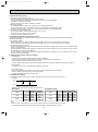
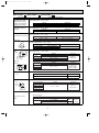
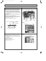
INFORMATION FOR THE AIR CONDITIONER WITH R410A REFRIGERANT
• This room air conditioner adopts an HFC refrigerant (R410A) which never destroys the ozone layer.
• Pay particular attention to the following points, though the basic installation procedure is same as that for R22 conditioners.
1 As R410A has working pressure approximate 1.6 times as high as that of R22, some special tools and piping parts/
materials are required. Refer to the table below.
2 Take sufficient care not to allow water and other contaminations to enter the R410A refrigerant during storage and
installation, since it is more susceptible to contaminations than R22.
3 For refrigerant piping, use clean, pressure-proof parts/materials specifically designed for R410A. (Refer to 2. Refrigerant
piping.)
4 Composition change may occur in R410A since it is a mixed refrigerant. When charging, charge liquid refrigerant to prevent
composition change.
New refrigerant
R410A
R22
Composition (Ratio)
HFC-32: HFC-125 (50%:50%)
R22 (100%)
Refrigerant handling
Pseudo-azeotropic refrigerant
Single refrigerant
Not included
Included
Refrigerant
Chlorine
A1/A1
A1
72.6
86.5
Boiling point (:)
-51.4
-40.8
Steam pressure [25:](Mpa)
1.557
0.94
64
44.4
Non combustible
Non combustible
0
0.055
Refrigerant
Safety group (ASHRAE)
Molecular weight
Saturated steam density [25:](Kg/K)
Combustibility
ODP w1
GWP w2
Refrigerant charge method
1730
1700
From liquid phase in cylinder
Gas phase
Possible
Possible
Kind
Incompatible oil
Compatible oil
Color
Non
Light yellow
Non
Non
oil
Refrigerating
Additional charge on leakage
Smell
w1 :Ozone Destruction Parameter : based on CFC-11
w2 :Global Warmth Parameter
: based on CO2
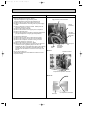
New Specification
Compressor
Previous refrigerant
Current Specification
The incompatible refrigerating oil easily separates from
Since refrigerant and refrigerating oil are compatible each,
refrigerant and is in the upper layer inside the suction muffler. refrigerating oil backs to the compressor through the lower
Raising position of the oil back hole enables to back the
position oil back hole.
refrigerating oil of the upper layer to flow back to the
compressor.
Suction muffler
Suction muffler
Compressor
Oil back hole
Compressor
Refrigerating oil
Oil back hole
Refrigerant
Refrigerating oil /Refrigerant
NOTE : The unit of pressure has been changed to MPa on the international system of units(SI unit system).
f [Gauge])
The conversion factor is: 1(MPa [Gauge]) =10.2(kgf/f
4
OB319--1.qxp
03.12.3 0:54 PM
Page 5
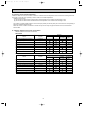
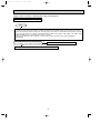
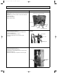
Conversion chart of refrigerant temperature and pressure
(MPa [Gauge])
4.0
Saturated liquid pressure
3.5
R410A
3.0
R22
2.5
2.0
NOTE : The unit of pressure has been changed to MPa on the
international system of units(SI unit system).
1.5
1.0
f [Gauge])
The conversion factor is: 1(MPa [Gauge]) =10.2(kgf/f
0.5
0.0
-0.5
-30 -20 -10
0
10
20
30
40
50
60
(:)
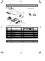
1.Tools dedicated for the air conditioner with R410A refrigerant
The following tools are required for R410A refrigerant. Some R22 tools can be substituted for R410A tools.
The diameter of the service port on the stop valve in outdoor unit has been changed to prevent any other refrigerant being
charged into the unit. Cap size has been changed from 7/16 UNF with 20 threads to 1/2 UNF with 20 threads.
R410A tools
Description
Can R22 tools be used?
R410A has high pressures beyond the measurement range of existing
gauges. Port diameters have been changed to prevent any other refrigerant
from being charged into the unit.
Gauge manifold
No
Charge hose
No
Gas leak detector
No
Hose material and cap size have been changed to improve the pressure
resistance.
Dedicated for HFC refrigerant.
Yes
6.35 mm and 9.52 mm
No
12.7 mm and 15.88 mm
Flare tool
Yes
Clamp bar hole has been enlarged to reinforce the spring strength in the tool.
Flare gauge
Vacuum pump
adapter
Electronic scale for
refrigerant charging
New
Provided for flaring work (to be used with R22 flare tool).
Provided to prevent the back flow of oil. This adapter enables you to use
vacuum pumps.
It is difficult to measure R410A with a charging cylinder because the
refrigerant bubbles due to high pressure and high-speed vaporization
Torque wrench
New
New
No : Not Substitutable for R410A
Yes : Substitutable for R410A
2.Refrigerant piping
1 Specifications
Use the refrigerant pipes that meet the following specifications.
Pipe
For liquid
For gas
Outside diameter
mm
Wall thickness
Insulation material
6.35/9.52
0.8 mm/0.8 mm
9.52
0.8 mm
Heat resisting foam plastic
12.7
0.8 mm
Specific gravity 0.045 Thickness 8 mm
15.88
1.0 mm
• Use a copper pipe or a copper-alloy seamless pipe with a thickness of 0.8 mm. Never use any pipe with a thickness less
than 0.8mm, as the pressure resistance is insufficient.
5
OB319--1.qxp
03.12.3 0:54 PM
Page 6
2 Flaring work and flare nut
Flaring work for R410A pipe differs from that for R22 pipe.
For details of flaring work, refer to Installation manual “FLARING WORK”.
Dimension of flare nut
Pipe diameter
mm
R410A
R22
6.35
17
17
9.52
22
22
12.7
26
24
15.88
29
27
3.Refrigerant oil
Apply the special refrigeration oil (accessories: packed with indoor unit) to the flare and the union seat surfaces.
4.Air purge
• Do not discharge the refrigerant into the atmosphere.
Take care not to discharge refrigerant into the atmosphere during installation, reinstallation, or repairs to the refrigerant
circuit.
• Use the vacuum pump for air purging for the purpose of environmental protection.
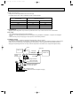
5.Additional charge
For additional charging, charge the refrigerant from liquid phase of the gas cylinder.
If the refrigerant is charged from the gas phase, composition change may occur in the refrigerant inside the cylinder and the
outdoor unit. In this case, ability of the refrigerating cycle decreases or normal operation can be impossible. However,
charging the liquid refrigerant all at once may cause the compressor to be locked. Thus, charge the refrigerant slowly.
Union
Stop valve
Indoor unit
Liquid pipe
Outdoor unit
Gas pipe
Refrigerant gas
cylinder
operating valve
Service port
Gauge manifold
valve (for R410A)
Charge hose (for R410A)
Refrigerant gas cylinder
for R410A with siphon
Refrigerant (liquid)
Electronic scale for refrigerant charging
6
OB319--1.qxp
03.12.3 0:54 PM
2
Page 7
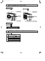
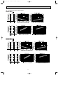
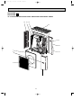
PART NAMES AND FUNCTIONS
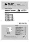
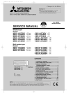
OUTDOOR UNIT
MXZ-A18WV- E1
MXZ-A26WV- E1
MXZ-A32WV- E1
Air inlet
(Back and side)
Air inlet
(Back and side)
Air outlet
Air outlet
Drain outlet
Drain outlet
ACCESSORIES
MXZ-A18WV- E1
MXZ-A26WV- E1
MXZ-A32WV- E1
1 Drain socket
1
2 Drain cap
2
3
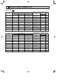
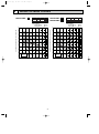
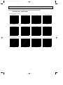
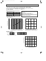
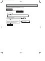
INDOOR/ OUTDOOR CORRESPONDENCE TABLE
MXZ-A18WV - E1
OUTDOOR UNIT
Combination of the
connectable indoor units
MXZ-A18WV-
E1
07+07
07+09
07+12
09+09
09+12
12+12
❈There is no combination other than this table.
7
OB319--1.qxp
03.12.3 0:54 PM
Page 8
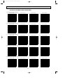
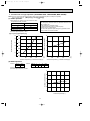
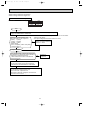
MXZ-A26WV - E1
OUTDOOR UNIT
Combination of the connectable indoor units
MXZ-A26WV- E1
❈There is no combination other than this table.
07+07
07+09
07+12
07+18
07+24
07+26
09+09
09+12
09+18
09+24
09+26
12+12
12+18
12+24
12+26
18+18
18+24
18+26
07+07+07
07+07+09
07+07+12
07+07+18
07+07+24
07+07+26
07+09+09
07+09+12
07+09+18
07+09+24
07+09+26
07+12+12
07+12+18
07+12+24
07+12+26
07+18+18
07+18+24
07+18+26
09+09+09
09+09+12
09+09+18
09+09+24
09+09+26
09+12+12
09+12+18
09+12+24
09+12+26
09+18+18
09+18+24
12+12+12
12+12+18
12+12+24
12+12+26
12+18+18
12+18+24
8
OB319--1.qxp
03.12.3 0:54 PM
Page 9
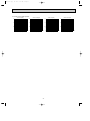
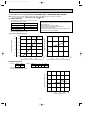
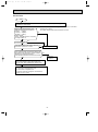
OUTDOOR UNIT
OUTDOOR UNIT
MXZ-A32WV- E1
MXZ-A32WV- E1
07+07
07+09
07+12
07+18
07+24
07+26
09+09
09+12
09+18
09+24
09+26
12+12
12+18
12+24
12+26
18+18
18+24
18+26
24+24
24+26
07+07+07
07+07+09
07+07+12
07+07+18
07+07+24
07+07+26
07+09+09
07+09+12
07+09+18
07+09+24
07+09+26
07+12+12
07+12+18
07+12+24
07+12+26
07+18+18
07+18+24
07+18+26
09+09+09
09+09+12
09+09+18
09+09+24
09+09+26
09+12+12
09+12+18
09+12+24
09+12+26
09+18+18
09+18+24
12+12+12
12+12+18
12+12+24
12+12+26
12+18+18
12+18+24
07+07+07+07
07+07+07+09
07+07+07+12
07+07+07+18
07+07+07+24
07+07+07+26
07+07+09+09
07+07+09+12
07+07+09+18
07+07+09+24
07+07+09+26
07+07+12+12
07+07+12+18
07+07+12+24
07+07+18+18
07+09+09+09
07+09+09+12
07+09+09+18
07+09+09+24
07+09+12+12
07+09+12+18
07+09+12+24
07+12+12+12
07+12+12+18
09+09+09+09
09+09+09+12
09+09+09+18
09+09+09+24
09+09+12+12
09+09+12+18
09+12+12+12
12+12+12+12
Combination of the connectable indoor units
Combination of the connectable indoor units
MXZ-A32WV - E1
❈There is no combination other than this table.
9
OB319--1.qxp
03.12.3 0:55 PM
Page 10
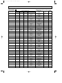
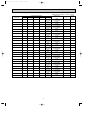
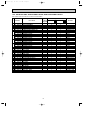
INDOOR UNITS COMBINATION
4
MXZ-A18WV - E1
Cooling capacity (kW)
Indoor units
combination
Unit A
Unit B
07
2.3
–
09
2.5
–
12
3.4
–
07+07
2.3
2.3
07+09
2.3
2.5
07+12
2.02
2.98
09+09
2.5
2.5
09+12
2.2
3.1
12+12
2.65
2.65
Total
2.3
(0.9-2.95)
2.5
(0.9-3.30)
3.4
(0.9-4.00)
4.6
(1.49-5.30)
4.8
(1.49-5.40)
5.0
(1.51-5.60)
5.0
(1.51-5.55)
5.3
(1.53-5.80)
5.4
(1.55-6.00)
NOTE: Electrical data is for outdoor unit only.
Current
Power
Outdoor unit
(A)
factor
power consumption
(%)
(kW)
230V
0.750
3.62
90
(0.225-1.000)
0.810
3.91
90
(0.225-1.070)
1.180
5.70
90
(0.220-1.450)
1.480
7.15
90
(0.370-2.060)
1.600
7.73
90
(0.370-2.070)
1.610
7.78
90
(0.365-2.100)
1.780
8.60
90
(0.370-2.105)
1.830
(0.365-2.110)
1.860
(0.370-2.130)
8.84
90
8.99
90
NOTE: Electrical data is for outdoor unit only.
Heating capacity (kW)
Indoor units
combination
Unit A
Unit B
07
3.3
–
09
3.6
–
12
4.0
–
07+07
3.05
3.05
07+09
2.97
3.23
07+12
2.62
3.88
09+09
3.25
3.25
09+12
2.78
3.77
12+12
3.30
3.30
Total
Outdoor unit
power consumption
(kW)
Current
(A)
230V
Power
factor
(%)
3.3
(0.9-4.0)
3.6
(0.9-4.5)
4.0
(0.9-4.8)
6.1
(1.53-6.70)
6.2
(1.53-6.80)
6.5
(1.55-7.00)
6.5
(1.55-7.0)
0.980
(0.225-1.115)
1.065
(0.225-1.195)
1.400
(0.220-1.680)
1.930
(0.300-2.070)
1.940
(0.300-2.040)
1.870
(0.295-1.980)
1.920
(0.295-2.010)
4.73
90
5.14
90
6.76
90
9.32
90
9.37
90
9.03
90
9.28
90
6.55
(1.56-7.1)
6.6
(1.58-7.2)
1.845
(0.295-1.950)
1.770
(0.290-1.850)
8.91
90
8.55
90
10
OB319--1.qxp
03.12.3 0:55 PM
Page 11
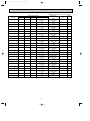
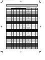
MXZ-A26WV - E1
Cooling capacity (kW)
Indoor units
combination
Unit A
Unit B
Unit C
07
2.3
–
–
09
2.5
–
–
12
3.4
–
–
18
5.0
–
–
24
6.0
–
–
26
7.1
–
–
07+07
2.3
2.3
–
07+09
2.1
2.7
–
07+12
2.1
3.6
–
07+18
2.01
5.18
–
07+24
1.62
5.57
–
07+26
1.52
5.67
–
09+09
2.5
2.5
–
09+12
2.52
3.37
–
09+18
2.4
4.8
–
09+24
1.96
5.23
–
09+26
1.85
5.34
–
12+12
3.4
3.4
–
12+18
2.88
4.32
–
12+24
2.4
4.8
–
12+26
2.27
4.92
–
18+18
3.6
3.6
–
18+24
3.08
4.11
–
18+26
2.94
4.25
–
07+07+07
2.3
2.3
2.3
07+07+09
2.16
2.16
2.77
07+07+12
1.93
1.93
3.32
07+07+18
1.58
1.58
4.05
07+07+24
1.32
1.32
4.55
07+07+26
1.26
1.26
4.68
07+09+09
2.01
2.59
2.59
07+09+12
1.8
2.31
3.09
07+09+18
1.48
1.9
3.81
07+09+24
1.26
1.62
4.32
Total
2.3
(1.4-3.0)
2.5
(1.4-3.3)
3.4
(1.5-4.3)
5.0
(1.6-5.6)
6.0
(1.6-6.6)
7.1
(1.7-7.4)
4.6
(2.0-5.4)
4.8
(2.0-5.8)
5.7
(2.0-6.6)
7.2
(2.0-7.7)
7.2
(2.0-8.0)
7.2
(2.0-8.2)
5.0
(2.0-6.2)
5.9
(2.0-7.3)
7.2
(2.0-8.5)
7.2
(2.0-8.5)
7.2
(2.0-8.5)
6.8
(2.0-8.5)
7.2
(2.0-8.5)
7.2
(2.0-8.5)
7.2
(2.0-8.5)
7.2
(2.1-8.5)
7.2
(2.1-8.5)
7.2
(2.1-8.5)
6.9
(2.9-8.1)
7.1
(2.9-8.5)
7.2
(2.9-8.5)
7.2
(2.9-8.5)
7.2
(2.9-8.5)
7.2
(2.9-8.5)
7.2
(2.9-8.5)
7.2
(2.9-8.5)
7.2
(2.9-8.5)
7.2
(2.9-8.5)
11
NOTE: Electrical data is for outdoor unit only.
Outdoor unit
Power
Current
power consumption
factor
(A)
(kW)
(%)
0.710
3.12
99
(0.400-0.920)
0.760
3.34
99
(0.400-1.010)
1.000
4.39
99
(0.400-1.290)
1.440
6.32
99
(0.420-1.630)
1.930
8.48
99
(0.400-2.130)
2.580
11.33
99
(0.410-2.710)
1.180
5.18
99
(0.600-1.600)
1.300
5.71
99
(0.600-1.770)
1.710
7.51
99
(0.600-2.200)
2.400
10.54
99
(0.560-2.710)
2.360
10.36
99
(0.560-3.050)
2.360
10.36
99
(0.560-3.200)
1.360
5.97
99
(0.580-1.950)
1.860
8.17
99
(0.580-2.670)
2.400
10.54
99
(0.560-3.200)
2.360
10.36
99
(0.560-3.170)
2.360
10.36
99
(0.560-3.170)
2.330
10.23
99
(0.580-3.260)
2.390
10.50
99
(0.560-3.210)
2.350
10.32
99
(0.560-3.180)
2.350
10.32
99
(0.560-3.180)
2.340
10.28
99
(0.590-3.160)
2.300
10.10
99
(0.570-3.110)
2.300
10.10
99
(0.570-3.110)
1.940
8.52
99
(0.690-2.410)
2.030
8.92
99
(0.690-2.510)
2.310
10.14
99
(0.690-2.620)
2.320
10.19
99
(0.700-2.570)
2.370
10.41
99
(0.680-2.530)
2.390
10.50
99
(0.680-2.530)
2.130
9.35
99
(0.690-2.620)
2.350
(0.690-2.620)
2.370
(0.700-2.570)
2.390
(0.680-2.530)
10.32
99
10.41
99
10.50
99
OB319--1.qxp
03.12.3 0:55 PM
Page 12
Cooling capacity (kW)
Indoor units
combination
Unit A
Unit B
Unit C
07+09+26
1.2
1.54
4.45
07+12+12
1.62
2.79
2.79
07+12+18
1.36
2.33
3.5
07+12+24
1.17
2.0
4.01
07+12+26
1.12
1.92
4.16
07+18+18
1.17
3.01
3.01
07+18+24
1.02
2.64
3.52
07+18+26
0.98
2.54
3.67
09+09+09
2.36
2.36
2.36
09+09+12
2.16
2.16
2.89
09+09+18
1.8
1.8
3.6
09+09+24
1.54
1.54
4.11
09+09+26
1.47
1.47
4.25
09+12+12
1.97
2.61
2.61
09+12+18
1.66
2.21
3.32
09+12+24
1.44
1.92
3.84
09+12+26
1.37
1.83
3.98
09+18+18
1.44
2.88
2.88
09+18+24
1.27
2.54
3.38
12+12+12
2.4
2.4
2.4
12+12+18
2.05
2.05
3.08
12+12+24
1.8
1.8
3.6
12+12+26
1.72
1.72
3.74
12+18+18
1.8
2.7
2.7
12+18+24
1.6
2.4
3.2
Total
7.2
(2.9-8.5)
7.2
(2.9-8.5)
7.2
(2.9-8.5)
7.2
(2.9-8.5)
7.2
(2.9-8.5)
7.2
(2.9-8.5)
7.2
(2.9-8.5)
7.2
(2.9-8.5)
7.1
(2.9-8.5)
7.2
(2.9-8.5)
7.2
(2.9-8.5)
7.2
(2.9-8.5)
7.2
(2.9-8.5)
7.2
(2.9-8.5)
7.2
(2.9-8.5)
7.2
(2.9-8.5)
7.2
(2.9-8.5)
7.2
(2.9-8.5)
7.2
(2.9-8.5)
7.2
(2.9-8.5)
7.2
(2.9-8.5)
7.2
(2.9-8.5)
7.2
(2.9-8.5)
7.2
(2.9-8.5)
7.2
(2.9-8.5)
12
NOTE: Electrical data is for outdoor unit only.
Outdoor unit
Power
Current
power consumption
factor
(A)
(kW)
(%)
2.390
10.50
99
(0.680-2.530)
2.350
(0.690-2.570)
2.320
(0.700-2.540)
2.350
(0.680-2.520)
2.350
(0.680-2.520)
2.330
(0.680-2.520)
2.300
(0.660-2.490)
2.300
(0.660-2.490)
2.030
(0.690-2.650)
2.350
(0.690-2.620)
2.370
(0.700-2.570)
2.390
(0.680-2.530)
2.390
(0.680-2.530)
2.350
(0.690-2.570)
2.380
(0.700-2.540)
2.350
(0.680-2.520)
2.350
(0.680-2.520)
2.330
(0.660-2.500)
2.300
(0.660-2.500)
2.090
(0.720-2.560)
2.280
(0.700-2.530)
2.260
(0.680-2.500)
2.260
(0.680-2.500)
2.240
(0.680-2.500)
2.220
(0.660-2.470)
10.32
99
10.19
99
10.32
99
10.32
99
10.23
99
10.10
99
10.10
99
8.92
99
10.32
99
10.41
99
10.50
99
10.50
99
10.32
99
10.45
99
10.32
99
10.32
99
10.23
99
10.10
99
9.18
99
10.01
99
9.93
99
9.93
99
9.84
99
9.75
99
OB319--1.qxp
03.12.3 0:55 PM
Page 13
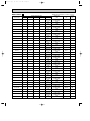
Heating capacity (kW)
Indoor units
combination
Unit A
Unit B
Unit C
07
3.3
–
–
09
3.6
–
–
12
4.0
–
–
18
7.2
–
–
24
7.9
–
–
26
8.6
–
–
07+07
3.3
3.3
–
07+09
3.02
3.88
–
07+12
2.69
4.61
–
07+18
2.49
6.41
–
07+24
2.03
6.97
–
07+26
1.91
7.09
–
09+09
3.6
3.6
–
09+12
3.26
4.34
–
09+18
3.0
6.0
–
09+24
2.45
6.55
–
09+26
2.31
6.69
–
12+12
4.0
4.0
–
12+18
3.6
5.4
–
12+24
3.0
6.0
–
12+26
2.84
6.16
–
18+18
4.5
4.5
–
18+24
3.86
5.14
–
18+26
3.68
5.32
–
07+07+07
2.9
2.9
2.9
07+07+09
2.67
2.67
3.44
07+07+12
2.42
2.42
4.15
07+07+18
1.96
1.96
5.06
07+07+24
1.65
1.65
5.68
07+07+26
1.57
1.57
5.85
07+09+09
2.52
3.24
3.24
07+09+12
2.25
2.89
3.85
07+09+18
1.85
2.38
4.76
07+09+24
1.57
2.02
5.4
Total
3.3
(1.2-4.2)
3.6
(1.2-4.5)
4.0
(1.2-4.8)
7.2
(1.4-8.2)
7.9
(1.4-8.6)
8.6
(1.6-9.2)
6.6
(1.8-7.2)
6.9
(1.8-8.7)
7.3
(1.8-9.2)
8.9
(1.8-9.9)
9.0
(1.8-9.9)
9.0
(1.8-9.9)
7.2
(1.8-9.1)
7.6
(1.8-9.5)
9.0
(1.8-10.1)
9.0
(1.8-10.1)
9.0
(1.8-10.1)
8.0
(1.8-9.8)
9.0
(1.8-10.5)
9.0
(1.8-10.5)
9.0
(1.8-10.5)
9.0
(1.9-11.0)
9.0
(1.9-11.0)
9.0
(1.9-11.0)
8.7
(2.6-10.6)
8.8
(2.6-11.0)
9.0
(2.6-11.0)
9.0
(2.6-11.0)
9.0
(2.6-11.0)
9.0
(2.6-11.0)
9.0
(2.6-11.0)
9.0
(2.6-11.0)
9.0
(2.6-11.0)
9.0
(2.6-11.0)
13
NOTE: Electrical data is for outdoor unit only.
Outdoor unit
Power
Current
power consumption
factor
(A)
(kW)
(%)
1.050
4.61
99
(0.340-1.380)
1.110
(0.340-1.510)
1.210
(0.330-1.570)
2.270
(0.330-2.710)
2.700
(0.330-3.060)
3.220
(0.360-3.520)
2.020
(0.480-2.760)
2.120
(0.480-3.000)
2.130
(0.480-3.110)
2.470
(0.460-3.140)
2.520
(0.460-3.140)
2.520
(0.460-3.140)
2.170
(0.480-3.140)
2.210
(0.480-3.230)
2.520
(0.460-3.260)
2.500
(0.460-3.260)
2.500
(0.460-3.260)
2.370
(0.480-3.230)
2.500
(0.460-3.420)
2.480
(0.460-3.420)
2.480
(0.460-3.420)
2.210
(0.440-3.260)
2.210
(0.440-3.260)
2.210
(0.440-3.260)
2.150
(0.530-3.150)
2.170
(0.530-3.170)
2.200
(0.530-3.190)
2.040
(0.510-3.040)
2.040
(0.510-3.040)
2.040
(0.510-3.040)
2.200
(0.530-3.260)
2.180
(0.530-3.180)
2.020
(0.510-3.040)
2.020
(0.510-3.040)
4.87
99
5.31
99
9.97
99
11.86
99
14.14
99
8.87
99
9.31
99
9.35
99
10.85
99
11.07
99
11.07
99
9.53
99
9.71
99
11.07
99
10.98
99
10.98
99
10.41
99
10.98
99
10.89
99
10.89
99
9.71
99
9.71
99
9.71
99
9.44
99
9.53
99
9.66
99
8.96
99
8.96
99
8.96
99
9.66
99
9.57
99
8.87
99
8.87
99
OB319--1.qxp
03.12.3 0:55 PM
Page 14
Heating capacity (kW)
Indoor units
combination
Unit A
Unit B
Unit C
07+09+26
1.5
1.92
5.57
07+12+12
2.03
3.48
3.48
07+12+18
1.7
2.91
4.37
07+12+24
1.46
2.51
5.02
07+12+26
1.4
2.4
5.2
07+18+18
1.46
3.76
3.76
07+18+24
1.28
3.3
4.4
07+18+26
1.23
3.17
4.58
09+09+09
3.0
3.0
3.0
09+09+12
2.7
2.7
3.6
09+09+18
2.25
2.25
4.5
09+09+24
1.92
1.92
5.14
09+09+26
1.84
1.84
5.31
09+12+12
2.45
3.27
3.27
09+12+18
2.07
2.76
4.15
09+12+24
1.8
2.4
4.8
09+12+26
1.72
2.29
4.97
09+18+18
1.8
3.6
3.6
09+18+24
1.58
3.17
4.23
12+12+12
3.0
3.0
3.0
12+12+18
2.57
2.57
3.85
12+12+24
2.25
2.25
4.5
12+12+26
2.16
2.16
4.68
12+18+18
2.25
3.37
3.37
12+18+24
2.0
3.0
4.0
Total
9.0
(2.6-11.0)
9.0
(2.6-11.0)
9.0
(2.7-11.0)
9.0
(2.7-11.0)
9.0
(2.7-11.0)
9.0
(2.7-11.0)
9.0
(2.7-11.0)
9.0
(2.7-11.0)
9.0
(2.6-11.0)
9.0
(2.6-11.0)
9.0
(2.6-11.0)
9.0
(2.6-11.0)
9.0
(2.6-11.0)
9.0
(2.6-11.0)
9.0
(2.7-11.0)
9.0
(2.7-11.0)
9.0
(2.7-11.0)
9.0
(2.7-11.0)
9.0
(2.7-11.0)
9.0
(2.6-11.0)
9.0
(2.7-11.0)
9.0
(2.7-11.0)
9.0
(2.7-11.0)
9.0
(2.7-11.0)
9.0
(2.7-11.0)
14
NOTE: Electrical data is for outdoor unit only.
Outdoor unit
Power
Current
power consumption
factor
(A)
(kW)
(%)
2.020
8.87
99
(0.510-3.040)
2.180
(0.530-3.150)
1.940
(0.510-2.950)
1.940
(0.510-2.950)
1.940
(0.510-2.950)
1.850
(0.490-2.830)
1.850
(0.490-2.830)
1.850
(0.490-2.830)
2.170
(0.530-3.230)
2.160
(0.530-3.180)
2.000
(0.510-3.030)
2.000
(0.510-3.030)
2.000
(0.510-3.030)
2.160
(0.530-3.150)
1.920
(0.510-2.950)
1.920
(0.510-2.950)
1.920
(0.510-2.950)
1.830
(0.490-2.830)
1.830
(0.490-2.830)
2.150
(0.530-3.050)
1.890
(0.510-2.890)
1.890
(0.510-2.890)
1.890
(0.510-2.890)
1.800
(0.490-2.770)
1.800
(0.490-2.770)
9.57
99
8.52
99
8.52
99
8.52
99
8.12
99
8.12
99
8.12
99
9.53
99
9.49
99
8.78
99
8.78
99
8.78
99
9.49
99
8.43
99
8.43
99
8.43
99
8.04
99
8.04
99
9.44
99
8.30
99
8.30
99
8.30
99
7.91
99
7.91
99
OB319--1.qxp
03.12.3 0:55 PM
Page 15
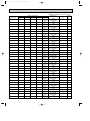
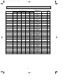
MXZ-A32WV - E1
Cooling capacity (kW)
Indoor units
combination
Unit A
Unit B
Unit C
Unit D
07
2.3
–
–
–
09
2.5
–
–
–
12
3.4
–
–
–
18
5.0
–
–
–
24
6.0
–
–
–
26
7.1
–
–
–
07+07
2.3
2.3
–
–
07+09
2.1
2.7
–
–
07+12
2.1
3.6
–
–
07+18
2.04
5.25
–
–
07+24
1.75
6.0
–
–
07+26
1.66
6.19
–
–
09+09
2.5
2.5
–
–
09+12
2.52
3.37
–
–
09+18
2.5
5.0
–
–
09+24
2.11
5.64
–
–
09+26
2.01
5.84
–
–
12+12
3.4
3.4
–
–
12+18
3.1
4.65
–
–
12+24
2.61
5.24
–
–
12+26
2.51
5.44
–
–
18+18
3.95
3.95
–
–
18+24
3.42
4.57
–
–
18+26
3.27
4.72
–
–
24+24
4.0
4.0
–
–
24+26
3.84
4.16
–
–
07+07+07
2.3
2.3
2.3
–
07+07+09
2.16
2.16
2.77
–
07+07+12
2.07
2.07
3.55
–
07+07+18
1.72
1.72
4.41
–
07+07+24
1.46
1.46
5.03
–
07+07+26
1.4
1.4
5.2
–
07+09+09
2.04
2.62
2.62
–
07+09+12
1.93
2.49
3.33
–
Total
2.3
(1.4-3.0)
2.5
(1.4-3.3)
3.4
(1.5-4.3)
5.0
(1.6-5.6)
6.0
(1.6-6.6)
7.1
(1.7-7.4)
4.6
(2.0-5.4)
4.8
(2.0-5.8)
5.7
(2.0-6.6)
7.3
(2.0-7.7)
7.75
(2.0-8.0)
7.85
(2.0-8.2)
5.0
(2.0-6.2)
5.9
(2.0-7.3)
7.5
(2.0-8.5)
7.75
(2.0-8.6)
7.85
(2.0-8.7)
6.8
(2.0-8.8)
7.75
(2.0-8.8)
7.85
(2.0-8.8)
7.95
(2.0-8.8)
7.9
(2.1-8.8)
8.0
(2.1-8.8)
8.0
(2.1-8.8)
8.0
(2.1-8.8)
8.0
(2.1-8.8)
6.9
(2.9-8.1)
7.1
(2.9-8.6)
7.7
(2.9-9.0)
7.85
(2.9-9.0)
7.95
(2.9-9.0)
8.0
(2.9-9.0)
7.3
(2.9-8.9)
7.75
(2.9-9.0)
15
NOTE: Electrical data is for outdoor unit only.
Outdoor unit
Power
Current
power consumption
factor
(A)
(kW)
(%)
0.710
3.12
99
(0.400-0.920)
0.760
(0.400-1.010)
1.000
(0.400-1.290)
1.440
(0.420-1.630)
1.930
(0.400-2.130)
2.580
(0.410-2.710)
1.180
(0.600-1.600)
1.300
(0.600-1.770)
1.710
(0.600-2.200)
2.480
(0.560-2.710)
2.750
(0.560-3.050)
2.810
(0.560-3.200)
1.360
(0.580-1.950)
1.860
(0.580-2.670)
2.580
(0.560-3.200)
2.750
(0.560-3.280)
2.810
(0.560-3.320)
2.330
(0.580-3.270)
2.760
(0.560-3.220)
2.730
(0.560-3.180)
2.780
(0.560-3.180)
2.780
(0.590-3.160)
2.800
(0.570-3.120)
2.800
(0.570-3.120)
2.690
(0.550-3.080)
2.690
(0.550-3.080)
1.940
(0.690-2.410)
2.030
(0.690-2.720)
2.310
(0.690-2.970)
2.320
(0.700-2.920)
2.370
(0.680-2.880)
2.390
(0.680-2.880)
2.130
(0.690-2.940)
2.350
(0.690-2.970)
3.34
99
4.39
99
6.32
99
8.48
99
11.33
99
5.18
99
5.71
99
7.51
99
10.89
99
12.08
99
12.34
99
5.97
99
8.17
99
11.33
99
12.08
99
12.34
99
10.23
99
12.12
99
11.99
99
12.21
99
12.21
99
12.30
99
12.30
99
11.81
99
11.81
99
8.52
99
8.92
99
10.14
99
10.19
99
10.41
99
10.50
99
9.35
99
10.32
99
OB319--1.qxp
03.12.3 0:55 PM
Page 16
Cooling capacity (kW)
Indoor units
combination
Unit A
Unit B
Unit C
Unit D
07+09+18
1.62
2.09
4.18
–
07+09+24
1.4
1.8
4.8
–
07+09+26
1.33
1.71
4.95
–
07+12+12
1.77
3.04
3.04
–
07+12+18
1.49
2.56
3.84
–
07+12+24
1.3
2.23
4.46
–
07+12+26
1.24
2.13
4.62
–
07+18+18
1.3
3.34
3.34
–
07+18+24
1.14
2.93
3.91
–
07+18+26
1.09
2.82
4.07
–
09+09+09
2.36
2.36
2.36
–
09+09+12
2.32
2.32
3.11
–
09+09+18
1.97
1.97
3.95
–
09+09+24
1.71
1.71
4.57
–
09+09+26
1.63
1.63
4.72
–
09+12+12
2.15
2.85
2.85
–
09+12+18
1.84
2.46
3.69
–
09+12+24
1.6
2.13
4.26
–
09+12+26
1.53
2.04
4.42
–
09+18+18
1.6
3.2
3.2
–
09+18+24
1.41
2.82
3.76
–
12+12+12
2.65
2.65
2.65
–
12+12+18
2.28
2.28
3.42
–
12+12+24
2.0
2.0
4.0
–
12+12+26
1.92
1.92
4.16
–
12+18+18
2.0
3.0
3.0
–
12+18+24
1.77
2.66
3.55
–
07+07+07+07
1.95
1.95
1.95
1.95
07+07+07+09
1.83
1.83
1.83
2.36
07+07+07+12
1.68
1.68
1.68
2.91
07+07+07+18
1.43
1.43
1.43
3.69
07+07+07+24
1.24
1.24
1.24
4.26
07+07+07+26
1.19
1.19
1.19
4.42
07+07+09+09
1.72
1.72
2.2
2.2
16
Total
7.9
(2.9-9.0)
8.0
(2.9-9.0)
8.0
(2.9-9.0)
7.85
(2.9-9.0)
7.9
(2.9-9.0)
8.0
(2.9-9.0)
8.0
(2.9-9.0)
8.0
(2.9-9.0)
8.0
(2.9-9.0)
8.0
(2.9-9.0)
7.1
(2.9-9.0)
7.75
(2.9-9.0)
7.9
(2.9-9.0)
8.0
(2.9-9.0)
8.0
(2.9-9.0)
7.85
(2.9-9.0)
8.0
(2.9-9.0)
8.0
(2.9-9.0)
8.0
(2.9-9.0)
8.0
(2.9-9.0)
8.0
(2.9-9.0)
7.95
(2.9-9.0)
8.0
(2.9-9.0)
8.0
(2.9-9.0)
8.0
(2.9-9.0)
8.0
(2.9-9.0)
8.0
(2.9-9.0)
7.8
(3.7-9.2)
7.85
(3.7-9.2)
7.95
(3.7-9.2)
8.0
(3.7-9.2)
8.0
(3.7-9.2)
8.0
(3.7-9.2)
7.85
(3.7-9.2)
NOTE: Electrical data is for outdoor unit only.
Outdoor unit
Power
Current
power consumption
factor
(A)
(kW)
(%)
2.370
10.41
99
(0.700-2.920)
2.390
(0.680-2.880)
2.390
(0.680-2.880)
2.350
(0.690-2.920)
2.320
(0.700-2.890)
2.350
(0.680-2.860)
2.350
(0.680-2.860)
2.330
(0.680-2.860)
2.300
(0.660-2.830)
2.300
(0.660-2.830)
2.030
(0.690-3.010)
2.350
(0.690-2.970)
2.370
(0.700-2.920)
2.390
(0.680-2.880)
2.390
(0.680-2.880)
2.350
(0.690-2.920)
2.380
(0.700-2.890)
2.350
(0.680-2.860)
2.350
(0.680-2.860)
2.330
(0.660-2.840)
2.300
(0.660-2.830)
2.280
(0.720-2.910)
2.280
(0.700-2.870)
2.260
(0.680-2.840)
2.260
(0.680-2.840)
2.240
(0.680-2.840)
2.220
(0.660-2.810)
2.180
(0.810-2.670)
2.190
(0.810-2.670)
2.210
(0.810-2.650)
2.150
(0.790-2.620)
2.130
(0.770-2.590)
2.130
(0.770-2.590)
2.190
(0.810-2.670)
10.50
99
10.50
99
10.32
99
10.19
99
10.32
99
10.32
99
10.23
99
10.10
99
10.10
99
8.92
99
10.32
99
10.41
99
10.50
99
10.50
99
10.32
99
10.45
99
10.32
99
10.32
99
10.23
99
10.10
99
10.01
99
10.01
99
9.93
99
9.93
99
9.84
99
9.75
99
9.57
99
9.62
99
9.71
99
9.44
99
9.35
99
9.35
99
9.62
99
OB319--1.qxp
03.12.3 0:55 PM
Page 17
Cooling capacity (kW)
Indoor units
combination
Unit A
Unit B
Unit C
Unit D
07+07+09+12
1.59
1.59
2.04
2.72
07+07+09+18
1.36
1.36
1.75
3.51
07+07+09+24
1.19
1.19
1.53
4.08
07+07+09+26
1.14
1.14
1.46
4.24
07+07+12+12
1.47
1.47
2.52
2.52
07+07+12+18
1.27
1.27
2.18
3.27
07+07+12+24
1.12
1.12
1.92
3.84
07+07+18+18
1.12
1.12
2.88
2.88
07+09+09+09
1.62
2.09
2.09
2.09
07+09+09+12
1.5
1.93
1.93
2.59
07+09+09+18
1.3
1.67
1.67
3.34
07+09+09+24
1.14
1.46
1.46
3.91
07+09+12+12
1.4
1.8
2.4
2.4
07+09+12+18
1.21
1.56
2.08
3.13
07+09+12+24
1.07
1.38
1.84
3.69
07+12+12+12
1.3
2.23
2.23
2.23
07+12+12+18
1.14
1.95
1.95
2.93
09+09+09+09
1.97
1.97
1.97
1.97
09+09+09+12
1.84
1.84
1.84
2.46
09+09+09+18
1.6
1.6
1.6
3.2
09+09+09+24
1.41
1.41
1.41
3.76
09+09+12+12
1.56
1.75
2.34
2.34
09+09+12+18
1.5
1.5
2.0
3.0
09+12+12+12
1.6
2.13
2.13
2.13
12+12+12+12
2.0
2.0
2.0
2.0
17
Total
7.95
(3.7-9.2)
8.0
(3.7-9.2)
8.0
(3.7-9.2)
8.0
(3.7-9.2)
8.0
(3.7-9.2)
8.0
(3.7-9.2)
8.0
(3.7-9.2)
8.0
(3.7-9.2)
7.9
(3.7-9.2)
7.95
(3.7-9.2)
8.0
(3.7-9.2)
8.0
(3.7-9.2)
8.0
(3.7-9.2)
8.0
(3.7-9.2)
8.0
(3.7-9.2)
8.0
(3.7-9.2)
8.0
(3.7-9.2)
7.9
(3.7-9.2)
8.0
(3.7-9.2)
8.0
(3.7-9.2)
8.0
(3.7-9.2)
8.0
(3.7-9.2)
8.0
(3.7-9.2)
8.0
(3.7-9.2)
8.0
(3.7-9.2)
NOTE: Electrical data is for outdoor unit only.
Outdoor unit
Power
Current
power consumption
factor
(A)
(kW)
(%)
2.210
99
9.71
(0.810-2.650)
2.150
(0.790-2.620)
2.130
(0.770-2.590)
2.130
(0.770-2.590)
2.210
(0.810-2.620)
2.120
(0.790-2.590)
2.100
(0.770-2.560)
2.070
(0.770-2.560)
2.140
(0.810-2.670)
2.210
(0.810-2.650)
2.150
(0.790-2.620)
2.130
(0.770-2.590)
2.210
(0.810-2.620)
2.120
(0.790-2.590)
2.100
(0.770-2.560)
2.200
(0.810-2.610)
2.080
(0.790-2.580)
2.140
(0.810-2.670)
2.220
(0.810-2.650)
2.150
(0.790-2.620)
2.130
(0.770-2.590)
2.210
(0.810-2.620)
2.120
(0.790-2.590)
2.200
(0.810-2.610)
2.190
(0.810-2.580)
9.44
99
9.35
99
9.35
99
9.71
99
9.31
99
9.22
99
9.09
99
9.40
99
9.71
99
9.44
99
9.35
99
9.71
99
9.31
99
9.22
99
9.66
99
9.13
99
9.40
99
9.75
99
9.44
99
9.35
99
9.71
99
9.31
99
9.66
99
9.62
99
OB319--1.qxp
03.12.3 0:55 PM
Page 18
Heating capacity (kW)
Indoor units
combination
Unit A
Unit B
Unit C
Unit D
07
3.3
–
–
–
09
3.6
–
–
–
12
4.0
–
–
–
18
7.2
–
–
–
24
7.9
–
–
–
26
8.6
–
–
–
07+07
3.3
3.3
–
–
07+09
3.02
3.88
–
–
07+12
2.69
4.61
–
–
07+18
2.49
6.41
–
–
07+24
2.12
7.28
–
–
07+26
1.99
7.41
–
–
09+09
3.6
3.6
–
–
09+12
3.26
4.34
–
–
09+18
3.0
6.0
–
–
09+24
2.56
6.84
–
–
09+26
2.42
6.98
–
–
12+12
4.0
4.0
–
–
12+18
3.76
5.64
–
–
12+24
3.13
6.27
–
–
12+26
2.97
6.43
–
–
18+18
4.7
4.7
–
–
18+24
4.03
5.37
–
–
18+26
3.85
5.55
–
–
24+24
4.7
4.7
–
–
24+26
4.51
4.89
–
–
07+07+07
2.9
2.9
2.9
–
07+07+09
2.67
2.67
3.44
–
07+07+12
2.53
2.53
4.33
–
07+07+18
2.05
2.05
5.28
–
07+07+24
1.73
1.73
5.93
–
07+07+26
1.64
1.64
6.11
–
07+09+09
2.49
3.2
3.2
–
07+09+12
2.35
3.02
4.02
–
Total
3.3
(1.2-4.2)
3.6
(1.2-4.5)
4.0
(1.2-4.8)
7.2
(1.4-8.2)
7.9
(1.4-8.6)
8.6
(1.6-9.2)
6.6
(1.8-7.2)
6.9
(1.8-8.7)
7.3
(1.8-9.2)
8.9
(1.8-9.9)
9.4
(1.8-9.9)
9.4
(1.8-9.9)
7.2
(1.8-9.1)
7.6
(1.8-9.5)
9.0
(1.8-10.1)
9.4
(1.8-10.1)
9.4
(1.8-10.1)
8.0
(1.8-9.8)
9.4
(1.8-10.5)
9.4
(1.8-10.5)
9.4
(1.8-10.5)
9.4
(1.9-11.2)
9.4
(1.9-11.2)
9.4
(1.9-11.2)
9.4
(1.9-11.2)
9.4
(1.9-11.2)
8.7
(2.6-10.6)
8.8
(2.6-11.1)
9.4
(2.6-11.6)
9.4
(2.6-11.6)
9.4
(2.6-11.6)
9.4
(2.6-11.6)
8.9
(2.6-11.6)
9.4
(2.6-11.6)
18
NOTE: Electrical data is for outdoor unit only.
Outdoor unit
Power
Current
power consumption
factor
(A)
(kW)
(%)
1.050
4.61
99
(0.340-1.380)
1.110
(0.340-1.510)
1.210
(0.330-1.570)
2.270
(0.330-2.710)
2.700
(0.330-3.060)
3.220
(0.360-3.520)
2.020
(0.480-2.760)
2.120
(0.480-3.000)
2.130
(0.480-3.110)
2.470
(0.460-3.140)
2.710
(0.460-3.140)
2.710
(0.460-3.140)
2.170
(0.480-3.140)
2.210
(0.480-3.230)
2.520
(0.460-3.260)
2.710
(0.460-3.260)
2.710
(0.460-3.260)
2.370
(0.480-3.230)
2.560
(0.460-3.420)
2.560
(0.460-3.420)
2.560
(0.460-3.420)
2.370
(0.440-3.320)
2.370
(0.440-3.320)
2.370
(0.440-3.320)
2.370
(0.440-3.320)
2.370
(0.440-3.320)
2.150
(0.530-3.060)
2.170
(0.530-3.330)
2.310
(0.530-3.400)
2.120
(0.510-3.330)
2.120
(0.510-3.330)
2.120
(0.510-3.330)
2.170
(0.530-3.420)
2.270
(0.530-3.410)
4.87
99
5.31
99
9.97
99
11.86
99
14.14
99
8.87
99
9.31
99
9.35
99
10.85
99
11.90
99
11.90
99
9.53
99
9.71
99
11.07
99
11.90
99
11.90
99
10.41
99
11.24
99
11.24
99
11.24
99
10.41
99
10.41
99
10.41
99
10.41
99
10.41
99
9.44
99
9.53
99
10.14
99
9.31
99
9.31
99
9.31
99
9.53
99
9.97
99
OB319--1.qxp
03.12.3 0:55 PM
Page 19
Heating capacity (kW)
Indoor units
combination
Unit A
Unit B
Unit C
Unit D
07+09+18
1.93
2.48
4.97
–
07+09+24
1.64
2.11
5.64
–
07+09+26
1.56
2.01
5.81
–
07+12+12
2.12
3.63
3.63
–
07+12+18
1.77
3.04
4.57
–
07+12+24
1.53
2.62
5.24
–
07+12+26
1.46
2.5
5.43
–
07+18+18
1.53
3.93
3.93
–
07+18+24
1.34
3.45
4.6
–
07+18+26
1.29
3.31
4.79
–
09+09+09
3.0
3.0
3.0
–
09+09+12
2.82
2.82
3.76
–
09+09+18
2.35
2.35
4.7
–
09+09+24
2.01
2.01
5.37
–
09+09+26
1.92
1.92
5.55
–
09+12+12
2.56
3.41
3.41
–
09+12+18
2.16
2.89
4.33
–
09+12+24
1.88
2.5
5.01
–
09+12+26
1.8
2.4
5.2
–
09+18+18
1.88
3.76
3.76
–
09+18+24
1.65
3.31
4.42
–
12+12+12
3.13
3.13
3.13
–
12+12+18
2.68
2.68
4.02
–
12+12+24
2.35
2.35
4.7
–
12+12+26
2.25
2.25
4.88
–
12+18+18
2.35
3.52
3.52
–
12+18+24
2.08
3.13
4.17
–
07+07+07+07
2.35
2.35
2.35
2.35
07+07+07+09
2.19
2.19
2.19
2.82
07+07+07+12
1.99
1.99
1.99
3.41
07+07+07+18
1.68
1.68
1.68
4.33
07+07+07+24
1.46
1.46
1.46
5.01
07+07+07+26
1.4
1.4
1.4
5.2
07+07+09+09
2.05
2.05
2.64
2.64
19
Total
9.4
(2.6-11.6)
9.4
(2.6-11.6)
9.4
(2.6-11.6)
9.4
(2.6-11.6)
9.4
(2.7-11.6)
9.4
(2.7-11.6)
9.4
(2.7-11.6)
9.4
(2.7-11.6)
9.4
(2.7-11.6)
9.4
(2.7-11.6)
9.0
(2.6-11.6)
9.4
(2.6-11.6)
9.4
(2.6-11.6)
9.4
(2.6-11.6)
9.4
(2.6-11.6)
9.4
(2.6-11.6)
9.4
(2.7-11.6)
9.4
(2.7-11.6)
9.4
(2.7-11.6)
9.4
(2.7-11.6)
9.4
(2.7-11.6)
9.4
(2.6-11.6)
9.4
(2.7-11.6)
9.4
(2.7-11.6)
9.4
(2.7-11.6)
9.4
(2.7-11.6)
9.4
(2.7-11.6)
9.4
(3.4-11.6)
9.4
(3.4-11.6)
9.4
(3.4-11.6)
9.4
(3.5-11.6)
9.4
(3.5-11.6)
9.4
(3.5-11.6)
9.4
(3.4-11.6)
NOTE: Electrical data is for outdoor unit only.
Outdoor unit
Power
Current
power consumption
factor
(A)
(kW)
(%)
2.100
9.22
99
(0.510-3.330)
2.100
(0.510-3.330)
2.100
(0.510-3.330)
2.210
(0.530-3.400)
2.050
(0.510-3.230)
2.050
(0.510-3.230)
2.050
(0.510-3.230)
1.960
(0.490-3.100)
1.960
(0.490-3.100)
1.960
(0.490-3.100)
2.170
(0.530-3.420)
2.250
(0.530-3.410)
2.090
(0.510-3.320)
2.090
(0.510-3.320)
2.090
(0.510-3.320)
2.190
(0.530-3.400)
2.030
(0.510-3.230)
2.030
(0.510-3.230)
2.030
(0.510-3.230)
1.940
(0.490-3.100)
1.940
(0.490-3.100)
2.170
(0.530-3.380)
2.010
(0.510-3.160)
2.010
(0.510-3.160)
2.010
(0.510-3.160)
1.920
(0.490-3.030)
1.920
(0.490-3.030)
2.020
(0.590-3.420)
1.990
(0.590-3.410)
1.960
(0.590-3.390)
1.910
(0.580-3.260)
1.910
(0.580-3.260)
1.910
(0.580-3.260)
1.980
(0.590-3.400)
9.22
99
9.22
99
9.71
99
9.00
99
9.00
99
9.00
99
8.61
99
8.61
99
8.61
99
9.53
99
9.88
99
9.18
99
9.18
99
9.18
99
9.62
99
8.92
99
8.92
99
8.92
99
8.52
99
8.52
99
9.53
99
8.83
99
8.83
99
8.83
99
8.43
99
8.43
99
8.87
99
8.74
99
8.61
99
8.39
99
8.39
99
8.39
99
8.70
99
OB319--1.qxp
03.12.3 0:55 PM
Page 20
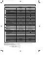
Heating capacity (kW)
Indoor units
combination
Unit A
Unit B
Unit C
Unit D
07+07+09+12
1.88
1.88
2.41
3.22
07+07+09+18
1.6
1.6
2.06
4.12
07+07+09+24
1.4
1.4
1.8
4.8
07+07+09+26
1.34
1.34
1.72
4.98
07+07+12+12
1.73
1.73
2.96
2.96
07+07+12+18
1.49
1.49
2.56
3.84
07+07+12+24
1.31
1.31
2.25
4.51
07+07+18+18
1.31
1.31
3.38
3.38
07+09+09+09
1.93
2.48
2.48
2.48
07+09+09+12
1.77
2.28
2.28
3.04
07+09+09+18
1.53
1.96
1.96
3.93
07+09+09+24
1.34
1.72
1.72
4.6
07+09+12+12
1.64
2.11
2.82
2.82
07+09+12+18
1.43
1.83
2.45
3.67
07+09+12+24
1.26
1.62
2.16
4.33
07+12+12+12
1.53
2.62
2.62
2.62
07+12+12+18
1.34
2.3
2.3
3.45
09+09+09+09
2.35
2.35
2.35
2.35
09+09+09+12
2.16
2.16
2.16
2.89
09+09+09+18
1.88
1.88
1.88
3.76
09+09+09+24
1.65
1.65
1.65
4.42
09+09+12+12
1.83
2.06
2.75
2.75
09+09+12+18
1.76
1.76
2.35
3.52
09+12+12+12
1.88
2.5
2.5
2.5
12+12+12+12
2.35
2.35
2.35
2.35
20
Total
9.4
(3.4-11.6)
9.4
(3.5-11.6)
9.4
(3.5-11.6)
9.4
(3.5-11.6)
9.4
(3.4-11.6)
9.4
(3.5-11.6)
9.4
(3.5-11.6)
9.4
(3.4-11.6)
9.4
(3.4-11.6)
9.4
(3.4-11.6)
9.4
(3.5-11.6)
9.4
(3.5-11.6)
9.4
(3.4-11.6)
9.4
(3.5-11.6)
9.4
(3.5-11.6)
9.4
(3.4-11.6)
9.4
(3.5-11.6)
9.4
(3.4-11.6)
9.4
(3.4-11.6)
9.4
(3.5-11.6)
9.4
(3.5-11.6)
9.4
(3.4-11.6)
9.4
(3.5-11.6)
9.4
(3.4-11.6)
9.4
(3.4-11.6)
NOTE: Electrical data is for outdoor unit only.
Outdoor unit
Power
Current
power consumption
factor
(A)
(kW)
(%)
1.940
99
8.52
(0.590-3.390)
1.890
(0.580-3.270)
1.890
(0.580-3.270)
1.890
(0.580-3.270)
1.910
(0.590-3.340)
1.820
(0.580-3.220)
1.820
(0.580-3.220)
1.750
(0.550-3.130)
1.960
(0.590-3.390)
1.920
(0.590-3.370)
1.870
(0.580-3.230)
1.870
(0.580-3.230)
1.890
(0.590-3.320)
1.800
(0.580-3.200)
1.800
(0.580-3.200)
1.860
(0.590-3.280)
1.780
(0.580-3.210)
1.950
(0.590-3.390)
1.910
(0.590-3.350)
1.860
(0.580-3.210)
1.860
(0.580-3.210)
1.870
(0.590-3.300)
1.780
(0.580-3.190)
1.840
(0.590-3.260)
1.930
(0.590-3.230)
8.30
99
8.30
99
8.30
99
8.39
99
7.99
99
7.99
99
7.69
99
8.61
99
8.43
99
8.21
99
8.21
99
8.30
99
7.91
99
7.91
99
8.17
99
7.82
99
8.56
99
8.39
99
8.17
99
8.17
99
8.21
99
7.82
99
8.08
99
8.48
99
OB319--1.qxp
03.12.3 0:55 PM
5
Page 21
SPECIFICATION
Outdoor model
Indoor units number
Indoor units total capacity (Connectable) ✽2
indoor units total capacity (Simultaneous operation) ✽2
m
Piping total length
m
Connecting pipe length
m
Height difference (Indoor ~ Outdoor)
m
Height difference (Indoor ~ Indoor)
Function
kW
Capacity [Rated (Min~Max.) Hz]✽4
R/h
Dehumidification
K /h
Outdoor air flow
A
Power outlet
A
Running current ✽4
W
Power input
A(kW)
Auxiliary heater
W
Crankcase heater
%
Power factor ✽4
A
Starting current ✽4
A
Compressor motor current
A
Fan motor current
Coefficient of performance (C.O.P)
Model
W
Output
Winding
"
resistance (at 20:)
Model
Winding
"
resistance (at 20:)
mm
Dimensions WOHOD
kg
Weight
w
dB
Sound level (High/Low ) ✽3
rpm
Fan speed (High/Low w) ✽3
Fan speed regulator ✽3
Refrigerant filling
kg
capacity (R410A)
cc
Refrigerating oil (Model)
k"
Thermistor RT61
k"
Thermistor RT62
k"
Thermistor RT63
k"
Thermistor RT6A,6B
k"
Thermistor RT65
k"
Thermistor RT68
2,460
20
8.98
1,860 (370~2,130)
8.55
1,770 (290~1,850)
—
—
90.0
8.98
8.41
7.98
0.57
2.90
3.73
SNV-092FJYH (ROTARY)
1,450
U-V 2.56
V-W 2.56 W-U 2.56
RA6V49-AA
WHT-BLK 139.9 BLK-YLW 34.2
BLK-RED 205.3
840(+69)o640o330
52
49/44 w
50/45 w
Fan
motor
Compressor
Electrical
data
Capacity
System
Outdoor unit power supply
MXZ-A18WV - E1
Single phase
230V,50Hz
2
Total capacity 24
Total capacity 24
Max. 30 (chargeless 20)
Max. 20
10
10
Cooling
Heating
5.4 (1.55~6.0)
6.6 (1.58~7.2)
—
—
725/620 w
2
Special
remarks
1.75
450 (NEO22)
13.4 (at 100:)
10.0 (at 25:)
10.0 (at 25:)
10.0 (at 25:)
17.0 (at 50:)
10.0 (at 25:)
NOTE: Test conditions are based on ISO 5151 (Refrigerant piping length (one way) :5m
w Reference value
✽1 Electrical data is for only outdoor unit.
✽2 However, please refer to “INDOOR/OUTDOOR CORRESPONDENCE TABLE” of page 7 for the combination.
✽3 These specifications are when all indoor units are operating.
✽4 Measured under rated operating frequency.
TEST CONDITIONS COOLING INDOOR
OUTDOOR
HEATING INDOOR
OUTDOOR
DB27.0°C WB19.0°C
DB35.0°C WB24.0°C
DB20.0°C
DB 7.0°C WB 6.0°C
21
OB319--1.qxp
03.12.3 0:55 PM
Page 22
Outdoor model
Indoor units number
Indoor units total capacity (Connectable)✽2
Indoor units total capacity (Simultaneous operation) ✽2
Piping total length
m
Connecting pipe length
m
Height difference (Indoor ~ Outdoor)
m
Height difference (Indoor ~ Indoor)
m
Function
Capacity [Rated (Min~Max.) Hz]✽4 kW
Dehumidification
R/h
Outdoor air flow
K /h
Power outlet
A
Running current ✽4
A
Power input
W
Auxiliary heater
A(kW)
Crankcase heater
W
Power factor ✽4
%
Starting current ✽4
A
Compressor motor current
A
Fan motor current
A
Coefficient of performance(C.O.P)
Model
Output
W
Winding
"
resistance(at20:)
Model
Winding
"
resistance(at20:)
Dimensions WOHOD
mm
Weight
kg
Sound level (High/Low w ) ✽3
dB
Fan speed (High/Low w) ✽3
rpm
Fan speed regulator ✽3
Refrigerant filling
kg
capacity(R410A)
Refrigerating oil (Model)
cc
Thermistor RT61
k"
Thermistor RT62
k"
Thermistor RT63
k"
Thermistor RT68
k"
Thermistor RT6A
k"
Thermistor RT6B
k"
Thermistor RT6C
k"
k"
Thermistor RT6D
Thermistor RT65
k"
Special
remarks
Fan
motor
Compressor
Electrical
data
Capacity
System
Outdoor unit power supply
MXZ-A32WV - E1
MXZ-A26WV - E1
Single phase
Single phase
230V,50Hz
230V,50Hz
2 to 3
2 to 4
Total capacity 54
Total capacity 54
Total capacity 54
Total capacity 54
Max. 50
Max. 70
Max. 25
Max. 25
10
10
10
10
Heating
Heating
Cooling
Cooling
9.0 (2.6~11.0)
9.4 (3.4~11.6)
7.2 (2.9~8.5)
8.0 (3.7~9.2)
—
—
—
—
2,630
2,630
2,530
2,530
25
25
9.44
8.48
9.18
9.62
2,090 (720~2,560) 2,150 (530~3,050) 2,190 (810~2,580) 1,930 (590~3,230)
—
—
—
—
99.0
99.0
9.44
9.62
9.24
8.28
8.98
9.42
0.2
0.2
4.19
4.87
3.44
3.65
TNB220FMCH (ROTARY)
TNB220FMCH (ROTARY)
2,000
2,100
U-V 1.41
U-V 1.41
V-W 1.41 W-U 1.41
V-W 1.41 W-U 1.41
PM8H60-UA
PM8H60-UA
BLK-WHT 15.2
BLK-WHT 15.2
WHT-RED 15.2 RED-BLK 15.2
WHT-RED 15.2 RED-BLK 15.2
900o900o320 (+35)
900o900o320 (+35)
69
70
w
w
w
48/46
48/46 w
46/44
46/44
w
w
w
560/490
560/490 w
550/490
550/490
2
2
3.5
3.5
870 (NEO22)
13.4 (at 100:)
10.0 (at 25:)
10.0 (at 25:)
10.0 (at 25:)
10.0 (at 25:)
10.0 (at 25:)
10.0 (at 25:)
10.0 (at 25:)
17.0 (at 50:)
870 (NEO22)
13.4 (at 100:)
10.0 (at 25:)
10.0 (at 25:)
10.0 (at 25:)
10.0 (at 25:)
10.0 (at 25:)
10.0 (at 25:)
10.0 (at 25:)
17.0 (at 50:)
NOTE: Test conditions are based on ISO5151 (Refrigerant piping length (one way): 5m)
w Reference value
✽1 Electrical data is for only outdoor unit.
✽2 However, please refer to “INDOOR/OUTDOOR CORRESPONDENCE TABLE” of page 8 or 9 for the combination.
✽3 These specifications are when all indoor units are operating.
✽4 Measured under rated operating frequency.
TEST CONDITIONS COOLING INDOOR
DB27.0°C WB19.0°C
OUTDOOR DB35.0°C WB24.0°C
HEATING INDOOR DB20.0°C
OUTDOOR DB 7.0°C WB 6.0°C
22
03.12.3 0:55 PM
Page 23
NOISE CRITERIA CURVES
6
MXZ-A18WV - E1
FAN SPEED FUNCTION SPL(dB(A))
High
Cooling
49
High
Heating
50
Test conditions.
Cooling :DB 35:
Heating :DB 7:
MXZ-A26WV - E1
MXZ-A32WV - E1
LINE
High
Cooling
46
High
Heating
48
LINE
WB 24:
WB 6:
OCTAVE BAND SOUND PRESSURE LEVEL, 0dB = 0.0002 MICRO BAR
90
80
70
NC-70
60
NC-60
50
NC-50
40
NC-40
30
NC-30
20
FAN SPEED FUNCTION SPL(dB(A))
Test conditions.
Cooling :DB 35:
Heating :DB 7:
WB 24:
WB 6:
90
OCTAVE BAND SOUND PRESSURE LEVEL, 0dB = 0.0002 MICRO BAR
OB319--1.qxp
APPROXIMATE
TERESHOLD OF
HEARING FOR
CONTINUOUS
NOISE
80
70
NC-70
60
NC-60
50
NC-50
40
NC-40
30
NC-30
20
NC-20
10
APPROXIMATE
TERESHOLD OF
HEARING FOR
CONTINUOUS
NOISE
NC-20
10
63
125
250
500
1000
2000
4000
8000
63
BAND CENTER FREQUENCIES, Hz
125
250
500
1000
2000
BAND CENTER FREQUENCIES, Hz
23
4000
8000
OB319--1.qxp
03.12.3 0:55 PM
7
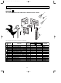
Page 24
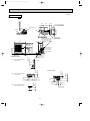
OUTLINES AND DIMENSIONS
Unit: mm
OUTDOOR UNIT
MXZ-A18WV - E1
REQUIRED SPACE
500
587
273
65
More than
100mm
34
Air in
Air in
Open as a rule
More than 200mm if the back,
both sides and top are open
40
Air out
840
*More than 100mm
200mm or more if
there are obstacles
to both sides
360
330
50
Drainage
3 holes
([33)
Open as a rule
More than100mm
if the front and both
sides are open
More than 350mm
* Note:
The dimensions given along the arrrows above are required to guarantee
the air conditioner's performance. Install the unit in as wide a place as
possible for later service or repairs.
69
121
Service panel
320
}
}
195
24
B UNIT
A UNIT
90 65 65 65
640
Liquid refrigerant valve
(flared [6.35)
Gas refrigerant valve
(flared [9.52)
03.12.3 0:55 PM
Page 25
Unit: mm
200
270
Air in
(27)
(16)
Rubber cushion
250
2-U-shape notched holes
(Base bolt M10)
Air out
40
(16)
35
(200)
500
35
Less than 25
(Base bolt length)
OUTDOOR UNIT
MXZ-A26WV - E1
355
387
Air in
Veranda
74
Base
Drainage holes 3-[33
Gas pipe
[9.52(flared)3/8(B,C unit)
[12.7(flared)1/2(A unit)
30
900
320
Indoor and
outdoor
connect wiring
23O45 hole
10
900
88
C unit connection
B unit connection
A unit connection
33
23
380.8
531.3
250
50
460
317
2-12O36 Oval hole
(Base bolt M10)
23
Liquid pipe
[6.35(flared)1/4
More than
100
More than
200
Note : Leave front and both sides
clearance fully.
More than
500
1.Installation space
More than
100
2.Service space
Note : Leave front and overhead
clearance fully.
Note : Leave front, overhead and
both sides clearance fully.
More than
350
More than
100
More than
500
More than
500
More than
100
More than
350
service space
25
More than
500
OB319--1.qxp
OB319--1.qxp
03.12.3 0:55 PM
Page 26
Unit: mm
35
200
500
250
270
(200)
Veranda
2-U-shape notched holes
(Base bolt M10)
(27)
(16)
Rubber cushion
Air in
35
Less than 25
(Base bolt length)
OUTDOOR UNIT
MXZ-A32WV - E1
40
(16)
74
355
387
Air in
Base
Air out
Drainage holes 3-[33
Gas pipe
[9.52(flared)3/8(C,D unit)
[12.7(flared)1/2(A,B unit)
900
30
320
10
900
88
23
480.8
531.3
D unit connection
C unit connection
B unit connection
A unit connection
33
317
350
460
50
Indoor and
outdoor
connect wiring
23O45 hole
2-12O36 Oval hole
(Base bolt M10)
23
Liquid pipe
[6.35(flared)1/4
More than
100
More than
200
More than
100
2.Service space
Note : Leave front and overhead
clearance fully.
More than
350
Note : Leave front, overhead and
both sides clearance fully.
More than
100
More than
500
More than
500
More than
100
More than
350
service space
26
More than
500
Note : Leave front and both sides
clearance fully.
More than
500
1.Installation space
OB319--1.qxp
03.12.3 0:55 PM
8
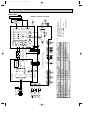
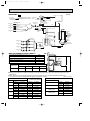
Page 27
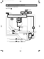
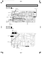
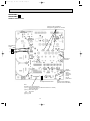
WIRING DIAGRAM
MXZ-A18WV - E1
OUTDOOR UNIT
3
ORN
X64
U
SYMBOL
AFM
CT61
CT761
C61
C62
C63
C65
DS61
DS62
F61
F801
F911
F912
IPM
L
21S4
NAME
ACTIVE FILTER MODULE
CURRENT TRANSFORMER
CURRENT TRANSFORMER
SMOOTHING CAPACITOR
SMOOTHING CAPACITOR
SMOOTHING CAPACITOR
OUTDOOR FAN CAPACITOR
DIODE MODULE
DIODE MODULE
FUSE(20A)
FUSE(1A)
FUSE(1A)
FUSE(3.15A)
POWER TRANSISTOR MODULE
REACTOR
BLK
C61
R62
TAB64
N
CN61 1 2 3
U BLK
W
SYMBOL
LEV(A)
LEV(B)
L63
MC
MF
NF
NR63
RT6A
RT6B
RT61
RT62
RT63
RT65
RT68
R62
T801
ELECTRONIC
CONTROL
P.C.BOARD
CN771
TAB67
6
LEV
(A)
CN772
AFM
F801
VWP
IPM
BLK
WHT
RED
CN912
CN911
1 2
NOISE
FILTER
P.C.BOARD
MC V
MF
TAB66
SSR61
7
TAB65
BRN
BRN
RED
YLW
BLK
WHT
1
DS62
CT761
C65
5 4 3
3
1
CN601
C63
3
1
CN602
X61
X62
L63
TAB4
F911
GRN/YLW
CT61
BLK
3
BLU TAB62
BLU
TAB2
GRN
LDE
TAB63
L
NR63
BLK TAB1
NF
F61
R64A R64B
C62
F912
CIRCUIT
BREAKER
POWER
TB1 BLK
SUPPLY
~/N
L
230V
50Hz
N PE
BLU
N
DS61
ORN TAB61
RED
3
BLU
N
CN851
TO INDOOR
UNIT No.B
CONNECTING
12V
TB2
CN901
TO INDOOR
UNIT No.A
CONNECTING
12V
MODEL WIRING DIAGRAM
6
LEV
(B)
CN663
1 2
CN661
1 2 3 4
CN662
1 2 3 4 5 6 7 8
RT65
RT6A RT6B
RT62 RT61 RT63 RT68
WHT
RED
NAME
EXPANSION VALVE A,COIL
EXPANSION VALVE B,COIL
NORMAL MODE CHOKE COIL
COMPRESSOR
OUTDOOR FAN MOTOR
NOISE FILTER
VARISTOR
GAS PIPE TEMPERATURE A THERMISTOR
GAS PIPE TEMPERATURE B THERMISTOR
DISCHARGE TEMPERATURE THERMISTOR
DEFROST THERMISTOR
EVAPORATOR TEMPERATURE THERMISTOR
FIN TEMPERATURE THERMISTOR
HIGH-PRESSURE PROTECT THERMISTOR
RESISTOR
SYMBOL
NAME
R64A RESISTOR
R64B RESISTOR
SSR61 SOLENOID COIL RELAY
TB1
TERMINAL BLOCK
TB2
TERMINAL BLOCK
T801
TRANSFORMER
X61
FAN MOTOR RELAY
FAN MOTOR RELAY
X62
X64
RELAY
21S4
R.V. COIL
NOTES 1.About the indoor side electric wiring
refer to the indoor unit electric wiring
diagram for servicing.
2.Use copper conductors only(for field wiring).
3.Symbols below indicate.
:Terminal block
:Connector
SG79J614H02
27
3
N
3
N
3
N
TB4
TB3
TB2
YLW
BLU
ORN
BLU
RED
BLU
21S4
LEV A
SYMBOL
LEV E
MC
MF
NR63
N/F
PFC
R64
R934A, B
RS1~4
RT6A~C
RT61
LEV B
CN901
1 2 3 4 5
X64
3
WHT
BLK
BLK
BLK
2
BLK
CN681
1 2
HPS
CN662
1 2 3 4 5 6 7 8
RT6A
RT6C
RT6B
4
1
YLW
RED
1 2 3 4 5 6 7
CN702
S
R
CN4
1 2
T801
RT62
RT63
RT61
RT68
LEV E
(3.15A)
(250V)
F801
LD2
CB1
RS4
RS3
CB3
R934B
R934A
1 2 3 CN801
LD1
CB2
POWER BOARD
HC932
GRN
LD9
IPM
CT2
CT1
W
V
U
CN932
CN931
U
YLW
BLU
ORN
PNK
GRY
BLK
WHT
RED
BLK
BLK
RED
WHT
BLK
MC
V
W
MF
SG79Y271H01
NOTES: 1.About the indoor side electric wiring
refer to the indoor unit electric wiring
diagram for servicing.
2.Use copper conductors only (for field wiring).
3.Symbols below indicate.
:Terminal block
:Connector
CN795
1 2 3 4 5 6
1 2
CN701
RS2
RS1
CN661
1 2 3 4 5 6 7 8
ELECTRONIC CONTROL P. C. BOARD
1 2 3 4 5
CN781
TAB4
4
BLK
NAME
SYMBOL
NAME
EXPANSION VALVE
RT62 DEFROST THERMISTOR
RT63 EVAPORATION TEMPERATURE THERMISTOR
COMPRESSOR
OUTDOOR FAN MOTOR (INNER FUSE) RT65 FIN TEMPERATURE THERMISTOR
VARISTOR
RT68 OUTDOOR HEAT EXCHANGER
TEMPERATURE THERMISTOR
NOISE FILTER
SSR61 SOLENOID COIL RELAY
POWER FACTOR CONTROLLER
RESISTOR
T801 TRANSFORMER
RESISTOR
TB1~4 TERMINAL BLOCK
RESISTOR
X64 RELAY
GAS PIPE TEMPERATURE THERMISTOR 21S4 R.V. COIL
DISCHARGE TEMPERATURE THERMISTOR
LEV C
(BLU)
CN793
1 2 3 4 5 6
GRN
GRN
R64
NR63
SSR61
N
1 2 3 CN912
(RED)
CN792
1 2 3 4 5 6
LDE2
(1A)
(250V)
F911
CT61
LDE1
N/F
F912
(3.15A)
(250V)
(WHT)
CN791
1 2 3 4 5 6
TAB2
TAB1
NAME
SMOOTHING CAPACITOR
CURRENT TRANSFORMER
CURRENT TRANSFORMER
FUSE (3.15A) (250V)
FUSE (1A) (250V)
FUSE (3.15A) (250V)
FET ARRAY
HIGH PRESSURE SWITCH
POWER TRANSISTOR MODULE
REACTOR
EXPANSION VALVE
INDOOR
UNIT(C)
INDOOR
UNIT(B)
INDOOR
UNIT(A)
SYMBOL
CB1~3
CT1, 2
CT61
F801
F911
F912
HC932
HPS
IPM
L
LEV A~C
TO INDOOR UNIT
CONNECTING 12V
CIRCUIT BREAKER
BLK
BLU
L
N
PE
POWER SUPPLY
~/N 230V~
TB1
50Hz
L
PFC
WHT
GRN/YLW
CN601
1 2 3
1 2 3
1 2 3
CN602
CN603
RED
BRN
BLU
ORN
YLW
WHT
BLK
NOISE FILTER
P. C. BOARD
BLK
RED
BRN
BLU
ORN
YLW
WHT
BLK
BLK
BLK
GRY
GRY
BLK
BLK
GRY
GRY
GRY
GRY
BLK
RED
BRN
BLU
ORN
YLW
WHT
BLK
BLK
BLK
RED
RED
2 1
RED
BRN
BLU
ORN
YLW
WHT
28
GRY
GRY
GRY
GRY
GRY
GRY
CN5
7 6 5 4 3 2 1
CN2
BLK
BLK
1 2
CN902
CN3
1 2
1 2
CN903
RED
MXZ-A26WV - E1
OUTDOOR UNIT
3 2 1
03.12.3 0:55 PM
5 4 3 2 1
RT65
OB319--1.qxp
Page 28
MODEL WIRING DIAGRAM
BLU
N
SYMBOL
CB1~3
CT1, 2
CT61
F801
F911
F912
HC932
HPS
IPM
L
LEV A~D
3
N TB5
3
N TB4
3
N TB3
3
N TB2
BRN
BLU
YLW
BLU
ORN
BLU
RED
BLU
LEV A
SYMBOL
LEV E
MC
MF
NR63
N/F
PFC
R64
R934A, B
RS1~4
RT6A~D
RT61
LEV B
1 2 3 4 5
CN781
4
TAB4
LEV D
CN681
1 2
HPS
NAME
EXPANSION VALVE
COMPRESSOR
OUTDOOR FAN MOTOR (INNER FUSE)
VARISTOR
NOISE FILTER
POWER FACTOR CONTROLLER
RESISTOR
RESISTOR
RESISTOR
GAS PIPE TEMPERATURE THERMISTOR
DISCHARGE TEMPERATURE THERMISTOR
LEV C
CN901
1 2 3 4 5
X64
3
WHT
BLK
BLK
BLK
2
BLK
L
4
1
YLW
RED
1 2 3 4 5 6 7
CN702
BLK
S
R
CN4
1 2
LEV E
(3.15A)
(250V)
F801
LD2
CB1
RS4
RS3
CB3
R934B
R934A
1 2 3 CN801
LD1
CB2
POWER BOARD
WHT
HC932
GRN
LD9
IPM
CT2
CT1
W
V
U
CN932
CN931
U
YLW
BLU
ORN
PNK
GRY
BLK
WHT
RED
BLK
BLK
RED
WHT
BLK
MC
V
W
MF
NOTES: 1.About the indoor side electric wiring
SYMBOL
NAME
refer to the indoor unit electric wiring
RT62 DEFROST THERMISTOR
diagram for servicing.
RT63 EVAPORATION TEMPERATURE THERMISTOR
RT65 FIN TEMPERATURE THERMISTOR
2.Use copper conductors only (for field wiring).
3.Symbols below indicate.
RT68 OUTDOOR HEAT EXCHANGER
TEMPERATURE THERMISTOR
:Terminal block
:Connector
SSR61 SOLENOID COIL RELAY
T801 TRANSFORMER
SG79Y270H01
TB1~5 TERMINAL BLOCK
X64 RELAY
21S4 R.V. COIL
RT63
RT61
RT68
RT62
RT6A
RT6C
RT6B
RT6D
CN795
1 2 3 4 5 6
T801
RS2
RS1
CN661
1 2 3 4 5 6 7 8
1 2
CN701
PFC
CN662
1 2 3 4 5 6 7 8
ELECTRONIC CONTROL P. C. BOARD
(GRN)
CN794
1 2 3 4 5 6
21S4
(BLU)
CN793
1 2 3 4 5 6
GRN
GRN
1 2 3 CN912
SSR61
NR63
R64
(RED)
CN792
1 2 3 4 5 6
LDE2
(1A)
(250V)
F911
CT61
LDE1
N/F
F912
(3.15A)
(250V)
(WHT)
CN791
1 2 3 4 5 6
TAB2
TAB1
NAME
SMOOTHING CAPACITOR
CURRENT TRANSFORMER
CURRENT TRANSFORMER
FUSE (3.15A) (250V)
FUSE (1A) (250V)
FUSE (3.15A) (250V)
FET ARRAY
HIGH PRESSURE SWITCH
POWER TRANSISTOR MODULE
REACTOR
EXPANSION VALVE
INDOOR
UNIT(D)
INDOOR
UNIT(C)
INDOOR
UNIT(B)
INDOOR
UNIT(A)
CIRCUIT BREAKER
BLK
L
PE
1 2 3
1 2 3
1 2 3
POWER SUPPLY
~/N 230V~
TB1
50Hz
CN601
CN602
CN603
1 2 3
RED
BRN
BLU
ORN
YLW
WHT
TO INDOOR UNIT
CONNECTING 12V
BLK
RED
BRN
BLU
ORN
YLW
WHT
BLK
RED
BRN
BLU
ORN
YLW
WHT
CN604
N
RED
BRN
BLU
ORN
YLW
WHT
BLK
BLK
BLK
GRN/YLW
BLK
2 1
NOISE FILTER
P. C. BOARD
BLK
BLK
BLK
RED
RED
CN5
7 6 5 4 3 2 1
CN2
BLK
BLK
GRY
GRY
GRY
GRY
GRY
GRY
GRY
GRY
29
GRY
GRY
BLK
BLK
GRY
GRY
GRY
GRY
RED
1 2
CN902
CN3
1 2
1 2
CN903
3 2 1
MXZ-A32WV - E1
OUTDOOR UNIT
5 4 3 2 1
03.12.3 0:55 PM
RED
BRN
BLU
ORN
YLW
WHT
RT65
OB319--1.qxp
Page 29
MODEL WIRING DIAGRAM
OB319--1.qxp
03.12.3 0:55 PM
Page 30
REFRIGERANT SYSTEM DIAGRAM
9
Unit:mm
MXZ-A18WV - E1
R.V. coil
heating ON
cooling OFF
Refrigerant flow in cooling
Refrigerant flow in heating
Discharge
temperature
thermistor
RT61
Compressor
{8
Muffler
{12
Stop valve
(with service port)
Indoor
Unit B
Indoor
Unit A
Stop valve
(with service port)
Gas pipe temperature
B thermistor
Muffler
4-way valve
{12
Gas pipe temperature
A thermistor
Capillary tube
{1.8✕{0.6✕750
Stop valve
Capillary tube
{3.0✕{2.0✕400
{6
Indoor
Unit A
Indoor
Unit B
Evaporation
temperature
thermistor
RT63
High-pressure
protect thermistor
RT68
Outdoor
heat
exchanger
Strainer
LEV (A)
Capillary tube
{3.0✕{1.8✕600
Strainer
#100
{6
Strainer
Stop valve #100
Defrost
thermistor
RT62
Capillary tube
{3.0✕{2.0✕400
LEV (B)
MAX REFRIGERANT PIPING LENGTH
Piping length each indoor unit (a, b)
20m
Total piping length (a+b)
30m
Height difference between units (H)
10m
Bending point for each unit
15
Total bending point
30
Indoor
units
a
Outdoor
unit
H
❋It does not matter which unit is higher.
H
Outdoor unit Refrigerant piping length (one way, 2 unit total)
precharged
20m
30m
25m
1,750
0
100
200
H
Calculation : Xg=20g/mx(Refrigerant piping length(m)-20)
b
● Refrigerant pipe diameter is different according to indoor unit to be connected. When using extension pipes, refer to the
tables below.
● When diameter of refrigerant pipe is different from that of outdoor unit union, use optional Different-diameter pipe.
For further information on Different-diameter pipe, see page BACK COVER.
Unit : mm (inch)
Indoor unit
class
07/09
12
Pipe diameter
Extension pipe diameter
Liquid
6.35(1/4)
Liquid
6.35(1/4)
Gas
9.52(3/8)
Gas
9.52(3/8)
Liquid
6.35(1/4)
Liquid
6.35(1/4)
Gas
12.7(1/2)
Gas
12.7(1/2)
Outdoor unit union diameter
For
Indoor unit A
Indoor unit B
30
Liquid
6.35(1/4)
Gas
9.52(3/8)
Liquid
6.35(1/4)
Gas
9.52(3/8)
OB319--2.qxp
03.12.3 0:56 PM
Page 31
MXZ-A26WV - E1
Unit:mm
[16
Compressor
R.V. coil
heating ON
cooling OFF
Discharge
temperature
thermistor RT61
High-pressure
switch
Refrigerant flow in cooling
Refrigerant flow in heating
Oil separator
Ball valve with
service port
Indoor unit
C
Indoor unit
B
Indoor unit
A
Unit C gas pipe
temperature thermistor
Unit B gas pipe
temperature thermistor
[16
Capillary tube
[2.5✕[0.6✕1000
Service port
4-way valve
[16
[9.52
[16
[16
Muffler
[9.52
Unit A gas pipe
temperature thermistor
Evaporation
temperature
thermistor
RT63
[12.7
Outdoor
heat
exchanger
Outdoor heat
exchanger
temperature
thermistor
RT68
Capillary tube
[2.0✕[0.6✕750
[6
Capillary tube
[4.0✕[2.8✕ 90
Indoor unit
A
Indoor unit
B
Indoor unit
C
[6.35
Strainer
LEV A
#100
Capillary tube
[4.0✕[2.8✕ 90
Strainer
LEV B
#100
Capillary tube
[4.0✕[2.8✕ 90
Strainer
#100
LEV C
Defrost
thermistor
RT62
Strainer
#100
Ball valve with
service port
Capillary tube
[4.0✕[2.4✕400
Distributor
LEV E
Receiver
[6.35
[9.52
Distributor
[6.35
MAX REFRIGERANT PIPING LENGTH
Piping length each indoor unit (a, b, c)
25m
Total piping length (a+b+c)
50m
Height difference between units (H)
10m
Bending point for each unit
25
Total bending point
50
Indoor
units
a
b
Outdoor
unit
H
H
❋It does not matter which unit is higher.
Outdoor unit Refrigerant piping length (one way, 3 unit total)
precharged
40m
50m
45m
3,500
0
100
H
c
200
Calculation : Xg=20g/mx(Refrigerant piping length(m)-40)
● Refrigerant pipe diameter is different according to indoor unit to be connected. When using extension pipes,refer to the
tables below.
● When diameter of refrigerant pipe is different from that of outdoor unit union, use optional Different-diameter pipe.
For further information on Different-diameter pipe,see page BACK COVER.
Unit : mm (inch)
Indoor unit
class
07/09
12
18
24
26
Pipe diameter
Liquid
6.35(1/4)
Extension pipe diameter
Liquid
6.35(1/4)
Gas
9.52(3/8)
Gas
9.52(3/8)
Liquid
6.35(1/4)
Liquid
6.35(1/4)
Outdoor unit union diameter
For
Indoor unit A
Indoor unit B
Gas
9.52(3/8) or 12.7(1/2)
Gas
12.7(1/2)
Liquid
6.35(1/4)
Liquid
6.35(1/4)
Gas
12.7(1/2)
Gas
12.7(1/2)
Liquid
6.35(1/4)
Liquid
6.35(1/4)
Gas
15.88(5/8)
Gas
15.88(5/8)
Liquid
9.52(3/8)
Liquid
9.52(3/8)
Gas
15.88(5/8)
Gas
15.88(5/8)
Indoor unit C
31
Liquid
6.35(1/4)
Gas
12.7(1/2)
Liquid
6.35(1/4)
Gas
9.52(3/8)
Liquid
6.35(1/4)
Gas
9.52(3/8)
OB319--2.qxp
03.12.3 0:56 PM
Page 32
Unit:mm
MXZ-A32WV - E1
[16
Compressor
R.V. coil
heating ON
cooling OFF
Indoor unit
D
Indoor unit
C
Indoor unit
B
Indoor unit
A
Discharge
temperature
thermistor RT61
High-pressure
switch
Refrigerant flow in cooling
Refrigerant flow in heating
Oil separator
Unit D gas pipe
temperature thermistor
[9.52
Unit C gas pipe
temperature thermistor
Unit B gas pipe
temperature thermistor
Unit A gas pipe
temperature thermistor
[16
Capillary tube
[2.5✕[0.6✕1000
Ball valve with
service port
Service port
4-way valve
[16
[9.52
[16
[16
Muffler
[12.7
Evaporation
temperature
thermistor
RT63
[12.7
Outdoor
heat
exchanger
Outdoor heat
exchanger
temperature
thermistor
RT68
Capillary tube
[2.0✕[0.6✕750
[6
Capillary tube
[4.0✕[2.8✕ 90
Strainer
#100
Indoor unit
B
Indoor unit
C
Indoor unit
D
LEV A
Strainer
#100
LEV B
Strainer
#100
LEV C
Strainer
#100
LEV D
[6.35
Ball valve with
service port
[6.35
Receiver
[9.52
[6.35
Distributor
[6.35
Piping length each indoor unit (a, b, c, d)
25m
Total piping length (a+b+c+d)
70m
Height difference between units (H)
10m
Bending point for each unit
Indoor
units
a
b
25
Total bending point
70
❋It does not matter which unit is higher.
Refrigerant piping length (one way, 4 unit total)
Outdoor unit
precharged
40m
60m
50m
70m
0
Capillary tube
[4.0✕[2.4✕400
Distributor
LEV E
MAX REFRIGERANT PIPING LENGTH
3,500
Defrost
thermistor
RT62
Strainer
#100
Indoor unit
A
400
200
600
Outdoor
unit
H
H
c
H
d
Calculation : Xg=20g/mx(Refrigerant piping length(m)-40)
● Refrigerant pipe diameter is different according to indoor unit to be connected. When using extension pipes,refer to the
tables below.
● When diameter of refrigerant pipe is different from that of outdoor unit union, use optional Different-diameter pipe.
For further information on Different-diameter pipe,see page BACK COVER.
Unit : mm (inch)
Indoor unit
class
07/09
12
18
24
26
Pipe diameter
Liquid
6.35(1/4)
Extension pipe diameter
Liquid
6.35(1/4)
Gas
9.52(3/8)
Gas
9.52(3/8)
Liquid
6.35(1/4)
Liquid
6.35(1/4)
Gas
9.52(3/8) or 12.7(1/2)
Gas
12.7(1/2)
Outdoor unit union diameter
For
Indoor unit A
Indoor unit B
Liquid
6.35(1/4)
Liquid
6.35(1/4)
Gas
12.7(1/2)
Gas
12.7(1/2)
Liquid
6.35(1/4)
Liquid
6.35(1/4)
Gas
15.88(5/8)
Gas
15.88(5/8)
Liquid
9.52(3/8)
Liquid
9.52(3/8)
Gas
15.88(5/8)
Gas
15.88(5/8)
Indoor unit C
32
Indoor unit D
Liquid
6.35(1/4)
Gas
12.7(1/2)
Liquid
6.35(1/4)
Gas
12.7(1/2)
Liquid
6.35(1/4)
Gas
9.52(3/8)
Liquid
6.35(1/4)
Gas
9.52(3/8)
OB319--2.qxp
03.12.3 0:56 PM
10
Page 33
PERFORMANCE CURVES
MXZ-A18WV- E1
MXZ-A26WV- E1
MXZ-A32WV- E1
The standard data contained in these specifications apply only to the operation of the air conditioner under normal conditions,
since operating conditions vary according to the areas where these units are installed. The following information has been provided to clarify the operating characteristics of the air conditioner under the conditions indicated by the performance curve.
(1) GUARANTEED VOLTAGE
198~264V
(2) AIR FLOW
Air flow should be set at MAX.
(3) MAIN READINGS
}
(1) Indoor intake air wet-bulb temperature :
°CWB
(2) Indoor outlet air wet-bulb temperature :
°CWB
Cooling
(3) Outdoor intake air dry-bulb temperature :
°CDB
(4) Total input:
W
(5) Indoor intake air dry-bulb temperature :
°CDB
Heating
(6) Outdoor intake air wet-bulb temperature :
°CWB
(7) Total input :
W
Indoor air wet/dry-bulb temperature difference on the left side of the chart on page 34 shows the difference between the
indoor intake air wet/dry-bulb temperature and the indoor outlet air wet/dry-bulb temperature for your reference at service.
}
How to measure the indoor air wet-bulb/dry-bulb temperature difference
1.
2.
3.
4.
5.
6.
7.
Attach at least 2 sets of wet-and dry-bulb thermometers to the indoor air intake as shown in the figure, and at least 2 sets
of wet-and dry-bulb thermometers to the indoor air outlet. The thermometers must be attached to the position where air
speed is high.
Attach at least 2 sets of wet-and dry-bulb thermometers to the outdoor air intake.
Cover the thermometers to prevent direct rays of the sun.
Check that the air filter is cleaned.
Open windows and doors of room.
Press the EMERGENCY OPERATION switch once(twice) to start the EMERGENCY COOL
(HEAT) MODE.
When system stabilizes after more than 15 minutes, measure temperature and take an average temperature.
10 minutes later, measure temperature again and check that the temperature does not change.
INDOOR UNIT
OUTDOOR UNIT
Wet-and dry-bulb
thermometers
Wet-and dry-bulb
thermometers
33
OB319--2.qxp
03.12.3 0:56 PM
Page 34
10-1. Capacity and the input curves
MXZ-A18WV- E1
8.5 9.7
7.1
7.8 8.8
6.4
7.0 7.9
5.8
6.3 7.1
5.1
5.6 6.3
12 class
7.8
09 class
9.3 10.6
07 class
8.5
25.4
24.0 25.9
23.4
22.2 23.9
21.5
20.3 21.9
19.5
18.5 19.9
17.6
16.6 17.9
11.1 12.0
12 class
12.9 13.9
11.7
09 class
14.8 15.9
07 class
15.6
13.7
MXZ-A26WV- E1
MXZ-A32WV- E1
7.1
7.8 8.8
10.8 11.3
13.9
6.4
7.0 7.9
9.7 10.1
12.5
5.8
6.3 7.1
8.7 9.0
11.1
5.1
5.6 6.3
7.7 8.0
9.7
09 class
26 class
15.4
24 class
17.0
11.9 12.4
18 class
13.1 13.7
8.5 9.7
12 class
9.3 10.6
7.8
07 class
8.5
25.4
24.0 25.9
31.4 31.9
35.1
23.4
22.2 23.9
29.0 29.4
32.4
21.5
20.3 21.9
26.6 27.0
29.7
19.5
18.5 19.9
24.1 24.5
27.0
17.6
16.6 17.9
21.7 22.1
24.3
14.5 14.7
16.2
26 class
11.1 12.0
24 class
18.9
11.7
18 class
21.6
16.9 17.2
12 class
19.3 19.6
12.9 13.9
09 class
14.8 15.9
07 class
15.6
13.7
34
OB319--2.qxp
03.12.3 0:56 PM
Page 35
10-2. Capacity and input correction by inverter output frequency
(OUTDOOR UNIT : MXZ-A18WV)
1. 07-class unit in single operation
1.5
<COOL>Capacity
<COOL>Total input
1.5
1.5
<HEAT>Capacity
1.5
1.0
1.0
1.0
1.0
0.5
0.5
0.5
0.5
0
50
100
150 Hz
0
50
Frequency
100
Frequency
150 Hz
0
50
100
Frequency
150 Hz
0
<HEAT>Total input
50
100
Frequency
150 Hz
2. 09-class unit in single operation
1.5
<COOL>Capacity
1.5
<COOL>Total input
1.5
<HEAT>Capacity
1.5
1.0
1.0
1.0
1.0
0.5
0.5
0.5
0.5
0
50
100
150 Hz
0
50
Frequency
100
Frequency
150 Hz
0
50
100
150 Hz
0
<HEAT>Total input
50
Frequency
100
Frequency
150 Hz
3. 12-class unit in single operation
1.5
<COOL>Capacity
1.5
<COOL>Total input
1.5
<HEAT>Capacity
1.5
1.0
1.0
1.0
1.0
0.5
0.5
0.5
0.5
0
50
100
Frequency
150 Hz
0
50
100
Frequency
150 Hz
0
50
100
Frequency
35
150 Hz
0
<HEAT>Total input
50
100
Frequency
150 Hz
OB319--2.qxp
03.12.3 0:56 PM
Page 36
(OUTDOOR UNIT:MXZ-A26WV, MXZ-A32WV)
1. 07-class unit in single operation
<COOL>Capacity
<HEAT>Capacity
<COOL>Total input
<HEAT>Total input
1.5
1.5
1.5
1.5
1.0
1.0
1.0
1.0
0.5
0.5
0.5
0.5
0
50
100
150 Hz
0
Frequency
50
100
0
150 Hz
50
100
150 Hz
0
Frequency
Frequency
50
100
150 Hz
Frequency
2. 09-class unit in single operation
<COOL>Capacity
<HEAT>Capacity
<COOL>Total input
<HEAT>Total input
1.5
1.5
1.5
1.5
1.0
1.0
1.0
1.0
0.5
0.5
0.5
0.5
0
50
100
150 Hz
0
Frequency
50
100
0
150 Hz
50
100
150 Hz
0
Frequency
Frequency
50
100
150 Hz
Frequency
3. 12-class unit in single operation
<COOL>Capacity
<COOL>Total input
<HEAT>Capacity
<HEAT>Total input
1.5
1.5
1.5
1.5
1.0
1.0
1.0
1.0
0.5
0.5
0.5
0.5
0
50
100
150 Hz
0
Frequency
50
100
150 Hz
0
Frequency
50
100
150 Hz
0
Frequency
50
100
150 Hz
Frequency
4. 18-class unit in single operation
<COOL>Capacity
<HEAT>Capacity
<COOL>Total input
<HEAT>Total input
1.5
1.5
1.5
1.5
1.0
1.0
1.0
1.0
0.5
0.5
0.5
0.5
0
50
100
150 Hz
0
Frequency
50
100
150 Hz
0
50
100
150 Hz
0
Frequency
Frequency
50
100
150 Hz
Frequency
5. 24-class unit in single operation
<COOL>Capacity
<HEAT>Capacity
<COOL>Total input
<HEAT>Total input
1.5
1.5
1.5
1.5
1.0
1.0
1.0
1.0
0.5
0.5
0.5
0.5
0
50
100
Frequency
150 Hz
0
50
100
150 Hz
0
50
100
Frequency
Frequency
36
150 Hz
0
50
100
Frequency
150 Hz
OB319--2.qxp
03.12.3 0:56 PM
Page 37
6. 26-class unit in single operation
<COOL>Capacity
<HEAT>Capacity
<COOL>Total input
<HEAT>Total input
1.5
1.5
1.5
1.5
1.0
1.0
1.0
1.0
0.5
0.5
0.5
0.5
0
50
100
Frequency
150 Hz
0
50
100
150 Hz
0
50
100
Frequency
Frequency
37
150 Hz
0
50
100
Frequency
150 Hz
OB319--2.qxp
03.12.3 0:56 PM
Page 38
10-3. Outdoor low pressure and outdoor unit current
1. 07-class unit in single operation (OUTDOOR UNIT : MXZ-A18WV)
NOTE:The unit of pressure has been changed to MPa on the international system of units(SI unit system).
f[Gauge])
The conversion factor is : 1(MPa[Gauge]) =10.2(kgf/f
(1) COOL operation
1Both indoor and outdoor units are under the same
temperature/humidity condition.
Dry-bulb temperature(°C) Relative humidity(%)
20
50
25
60
30
70
<How to work fixed-frequency operation>
1.Set emergency switch to COOL or HEAT. The switch is located
on indoor unit.
2.Press emergency operation button.
3.Compressor starts running at rated frequency.
4.Indoor fan runs at High speed and continues for 30 minutes.
5.To cancel this operation, press emergency operation button
or any button on remote controller.
2Air flow speed : High
3Inverter output frequency : 33Hz
14
1.4
13
1.3
12
1.2
11
1.1
10
1.0
9
0.9
8
0.8
7
0.7
6
0.6
5
0.5
15
5
Outdoor unit current (A)
Outdoor low pressure
(kgf/F[Gauge])(MPa[Gauge])
1.5
15
33Hz
20
50
25
60
33Hz
3
2
1
35 (:)
(%)
30
70
4
15
Ambient temperature(:)/ Ambient humidity(%)
20
50
25
60
35 (:)
(%)
30
70
Ambient temperature(:)/ Ambient humidity(%)
(2) HEAT operation
DB(°C)
20.0
Outdoor DB(°C)
WB(°C) 14.5
➁ Set air flow to High speed.
➂ Inverter output frequency is 45Hz.
WB(°C)
2
7
15
20.0
1
6
12
14.5
8
Outdoor unit current (A)
① Indoor
7
45Hz
6
5
4
3
2
5
10
15
20
Ambient temperature(:)
38
25
OB319--2.qxp
03.12.3 0:56 PM
Page 39
2. 09-class unit in single operation (OUTDOOR UNIT : MXZ-A18WV)
NOTE:The unit of pressure has been changed to MPa on the international system of units(SI unit system).
f[Gauge])
The conversion factor is : 1(MPa[Gauge]) =10.2(kgf/f
(1) COOL operation
1Both indoor and outdoor units are under the same
temperature/humidity condition.
Dry-bulb temperature(°C)
Relative humidity(%)
20
50
25
60
30
70
<How to work fixed-frequency operation>
1.Set emergency switch to COOL or HEAT. The switch is located
on indoor unit.
2.Press emergency run ON/OFF button.
3.Compressor starts running at rated frequency.
4.Indoor fan runs at High speed and continues for 30 minutes.
5.To cancel this operation, press emergency operation button
or any button on remote controller.
2Air flow speed : High
3Inverter output frequency : 33Hz
13
1.3
12
1.2
11
1.1
10
1.0
9
0.9
8
0.8
7
0.7
6
0.6
5
0.5
15
5
Outdoor unit current (A)
Outdoor low pressure
(kgf/F[Gauge])(MPa[Gauge])
1.5
15
1.4
14
33Hz
20
50
25
60
33Hz
3
2
1
15
35 (:)
(%)
30
70
4
Ambient temperature(:)/ Ambient humidity(%)
20
50
25
60
35 (:)
(%)
30
70
Ambient temperature(:)/ Ambient humidity(%)
(2) HEAT operation
DB(°C)
20.0
Outdoor DB(°C)
WB(°C) 14.5
➁ Set air flow to High speed.
➂ Inverter output frequency is 45Hz.
WB(°C)
2
7
15
20.0
1
6
12
14.5
8
Outdoor unit current (A)
① Indoor
7
45Hz
6
5
4
3
2
5
10
15
20
Ambient temperature(:)
39
25
OB319--2.qxp
03.12.3 0:56 PM
Page 40
3. 12-class unit in single operation (OUTDOOR UNIT : MXZ-A18WV)
NOTE:The unit of pressure has been changed to MPa on the international system of units(SI unit system).
f[Gauge])
The conversion factor is : 1(MPa[Gauge]) =10.2(kgf/f
(1) COOL operation
1Both indoor and outdoor units are under the same
temperature/humidity condition.
Dry-bulb temperature(°C)
Relative humidity(%)
20
50
25
60
30
70
<How to work fixed-frequency operation>
1.Set emergency switch to COOL or HEAT. The switch is located
on indoor unit.
2.Press emergency operation button.
3.Compressor starts running at rated frequency.
4.Indoor fan runs at HI speed and continues for 30 minutes.
5.To cancel this operation, press emergency operation button
or any button on remote controller.
2Air flow speed : High
3Inverter output frequency : 33Hz
13
1.3
12
1.2
11
1.1
10
1.0
9
0.9
8
0.8
7
0.7
6
0.6
5
0.5
15
5
Outdoor unit current (A)
Outdoor low pressure
(kgf/F[Gauge])(MPa[Gauge])
1.5
15
1.4
14
33Hz
20
50
25
60
33Hz
3
2
1
15
35 (:)
(%)
30
70
4
Ambient temperature(:)/ Ambient humidity(%)
20
50
25
60
35 (:)
(%)
30
70
Ambient temperature(:)/ Ambient humidity(%)
(2) HEAT operation
DB(°C)
20.0
Outdoor DB(°C)
WB(°C) 14.5
➁ Set air flow to High speed.
➂ Inverter output frequency is 45Hz.
WB(°C)
2
7
15
20.0
1
6
12
14.5
8
Outdoor unit current (A)
① Indoor
7
45Hz
6
5
4
3
2
5
10
15
20
Ambient temperature(:)
40
25
OB319--2.qxp
03.12.3 0:56 PM
Page 41
4. 07-class unit in single operation (OUTDOOR UNIT : MXZ-A26WV, MXZ-A32WV)
NOTE:The unit of pressure has been changed to MPa on the international system of units(SI unit system).
f[Gauge])
The conversion factor is : 1(MPa[Gauge]) =10.2(kgf/f
(1) COOL operation
1Both indoor and outdoor units are under the same
temperature/humidity condition.
Dry-bulb temperature(°C) Relative humidity(%)
20
50
25
60
30
70
<How to work fixed-frequency operation>
1.Set emergency switch to COOL or HEAT.The switch is located on indoor unit.
2.Press emergency operation button.
3.Compressor starts running at rated frequency.
4.Indoor fan runs at High speed and continues for 30 minutes.
5.To cancel this operation,press emergency operation button
or any button on remote controller.
2Air flow speed : High
3Inverter output frequency : 24Hz
(kgf/F[Gauge]) (MPa[Gauge])
1.2
12
5
24Hz
1.1
10
1.0
9
0.9
8
0.8
Outdoor unit current (A)
Outdoor low pressure
11
7
0.7
6
0.6
15
20
50
25
60
35 (:)
30
70
4
24Hz
3
2
1
15
(%)
Ambient temperature(:)/ Ambient humidity(%)
20
50
30
70
25
60
35 (:)
(%)
Ambient temperature(:)/ Ambient humidity(%)
(2) HEAT operation
DB(°C)
20.0
Outdoor DB(°C)
WB(°C) 14.5
➁ Set air flow to High speed.
➂ Inverter output frequency is 32Hz.
WB(°C)
2
7
15
20.0
1
6
12
14.5
7
Outdoor unit current (A)
① Indoor
6
32Hz
5
4
3
2
5
10
15
20
Ambient temperature(:)
41
25
OB319--2.qxp
03.12.3 0:56 PM
Page 42
5. 09-class unit in single operation (OUTDOOR UNIT : MXZ-A26WV, MXZ-A32WV)
NOTE:The unit of pressure has been changed to MPa on the international system of units(SI unit system).
f[Gauge])
The conversion factor is : 1(MPa[Gauge]) =10.2(kgf/f
(1) COOL operation
1Both indoor and outdoor units are under the same
temperature/humidity condition.
Dry-bulb temperature(°C)
Relative humidity(%)
20
50
25
60
30
70
<How to work fixed-frequency operation>
1.Set emergency switch to COOL or HEAT.The switch is located on indoor unit.
2.Press emergency operation button.
3.Compressor starts running at rated frequency.
4.Indoor fan runs at High speed and continues for 30 minutes.
5.To cancel this operation,press emergency operation button
or any button on remote controller.
2Air flow speed : High
3Inverter output frequency : 24Hz
(kgf/F[Gauge]) (MPa[Gauge])
1.2
12
5
24Hz
Outdoor unit current (A)
Outdoor low pressure
11
1.1
10
1.0
9
0.9
8
0.8
7
0.7
6
0.6
15
20
50
25
60
35 (:)
30
70
4
24Hz
3
2
1
15
(%)
Ambient temperature(:)/ Ambient humidity(%)
20
50
30
70
25
60
35 (:)
(%)
Ambient temperature(:)/ Ambient humidity(%)
(2) HEAT operation
DB(°C)
20.0
Outdoor DB(°C)
WB(°C) 14.5
➁ Set air flow to High speed.
➂ Inverter output frequency is 32Hz.
WB(°C)
2
7
15
20.0
1
6
12
14.5
7
Outdoor unit current (A)
① Indoor
6
32Hz
5
4
3
2
5
10
15
20
Ambient temperature(:)
42
25
OB319--2.qxp
03.12.3 0:56 PM
Page 43
6. 12-class unit in single operation (OUTDOOR UNIT : MXZ-A26WV, MXZ-A32WV)
NOTE:The unit of pressure has been changed to MPa on the international system of units(SI unit system).
f[Gauge])
The conversion factor is : 1(MPa[Gauge]) =10.2(kgf/f
(1) COOL operation
1Both indoor and outdoor units are under the same
temperature/humidity condition.
Dry-bulb temperature(°C)
Relative humidity(%)
20
50
25
60
30
70
<How to work fixed-frequency operation>
1.Set emergency switch to COOL or HEAT.The switch is located on indoor unit.
2.Press emergency operation button.
3.Compressor starts running at rated frequency.
4.Indoor fan runs at High speed and continues for 30 minutes.
5.To cancel this operation,press emergency operation button
or any button on remote controller.
2Air flow speed : High
3Inverter output frequency : 24Hz
(kgf/F[Gauge]) (MPa[Gauge])
1.3
13
5
1.2
11
1.1
10
1.0
9
0.9
Outdoor unit current (A)
Outdoor low pressure
24Hz
12
8
0.8
7
0.7
15
20
50
25
60
35 (:)
30
70
4
24Hz
3
2
1
15
(%)
Ambient temperature(:)/ Ambient humidity(%)
20
50
30
70
25
60
35 (:)
(%)
Ambient temperature(:)/ Ambient humidity(%)
(2) HEAT operation
① Indoor
DB(°C)
20.0
Outdoor DB(°C)
2
7
15
20.0
WB(°C)
14.5
WB(°C)
1
6
12
14.5
➁ Set air flow to High speed.
➂ Inverter output frequency is 32Hz.
Outdoor unit current (A)
7
6
32Hz
5
4
3
2
5
10
15
20
Ambient temperature(:)
43
25
OB319--2.qxp
03.12.3 0:56 PM
Page 44
7. 18-class unit in single operation (OUTDOOR UNIT : MXZ-A26WV, MXZ-A32WV)
NOTE:The unit of pressure has been changed to MPa on the international system of units(SI unit system).
f[Gauge])
The conversion factor is : 1(MPa[Gauge]) =10.2(kgf/f
(1) COOL operation
① Both indoor and outdoor units are under the same
temperature/humidity condition.
Dry-bulb temperature(°C)
Relative humidity(%)
20
50
25
60
30
➁ Air flow speed : High
➂ Inverter output frequency : 24Hz
70
(kgf/F[Gauge]) (MPa[Gauge])
1.3
13
5
24Hz
1.2
11
1.1
10
1.0
9
0.9
Outdoor unit current (A)
Outdoor low pressure
12
<How to work fixed-frequency operation>
1.Set emergency switch to COOL or HEAT.The switch is located on indoor unit.
2.Press emergency operation button.
3.Compressor starts running at rated frequency.
4.Indoor fan runs at High speed.
5.To cancel this operation,press emergency operation button
or any button on remote controller.
8
0.8
7
0.7
15
20
50
25
60
35 (:)
30
70
4
24Hz
3
2
1
15
(%)
Ambient temperature(:)/ Ambient humidity(%)
20
50
30
70
25
60
35 (:)
(%)
Ambient temperature(:)/ Ambient humidity(%)
(2) HEAT operation
DB(°C)
20.0
Outdoor DB(°C)
WB(°C) 14.5
➁ Set air flow to High speed.
➂ Inverter output frequency is 32Hz.
WB(°C)
2
7
15
20.0
1
6
12
14.5
7
Outdoor unit current (A)
① Indoor
6
5
32Hz
4
3
2
5
10
15
20
Ambient temperature(:)
44
25
OB319--2.qxp
03.12.3 0:56 PM
Page 45
8. 24-class unit in single operation (OUTDOOR UNIT : MXZ-A26WV, MXZ-A32WV)
NOTE:The unit of pressure has been changed to MPa on the international system of units(SI unit system).
f[Gauge])
The conversion factor is : 1(MPa[Gauge]) =10.2(kgf/f
(1) COOL operation
① Both indoor and outdoor units are under the same
temperature/humidity condition.
Dry-bulb temperature(°C)
Relative humidity(%)
20
50
25
60
30
70
➁ Air flow speed : High
➂ Inverter output frequency : 24Hz
<How to work fixed-frequency operation>
1.Set emergency switch to COOL or HEAT.The switch is located on indoor unit.
2.Press emergency operation button.
3.Compressor starts running at rated frequency.
4.Indoor fan runs at High speed.
5.To cancel this operation,press emergency operation button
or any button on remote controller.
(kgf/F[Gauge]) (MPa[Gauge])
1.4
14
5
24Hz
1.3
12
1.2
11
1.1
10
1.0
Outdoor unit current (A)
Outdoor low pressure
13
9
0.9
8
0.8
15
20
50
25
60
35 (:)
30
70
4
24Hz
3
2
1
15
(%)
Ambient temperature(:)/ Ambient humidity(%)
20
50
30
70
25
60
35 (:)
(%)
Ambient temperature(:)/ Ambient humidity(%)
(2) HEAT operation
① Indoor
DB(°C)
20.0
Outdoor DB(°C)
2
7
15
20.0
WB(°C)
14.5
WB(°C)
1
6
12
14.5
➁ Set air flow to High speed.
➂ Inverter output frequency is 32Hz.
Outdoor unit current (A)
7
6
5
32Hz
4
3
2
5
10
15
20
Ambient temperature(:)
45
25
OB319--2.qxp
03.12.3 0:56 PM
Page 46
9. 26-class unit in single operation (OUTDOOR UNIT : MXZ-A26WV, MXZ-A32WV)
NOTE:The unit of pressure has been changed to MPa on the international system of units(SI unit system).
f[Gauge])
The conversion factor is : 1(MPa[Gauge]) =10.2(kgf/f
(1) COOL operation
① Both indoor and outdoor units are under the same
temperature/humidity condition.
Dry-bulb temperature(°C)
Relative humidity(%)
20
50
25
60
30
➁ Air flow speed : High
➂ Inverter output frequency : 24Hz
70
<How to work fixed-frequency operation>
1.Set emergency switch to COOL or HEAT.The switch is located on indoor unit.
2.Press emergency operation button.
3.Compressor starts running at rated frequency.
4.Indoor fan runs at High speed.
5.To cancel this operation,press emergency operation button
or any button on remote controller.
(kgf/F[Gauge]) (MPa[Gauge])
1.4
14
5
24Hz
1.3
Outdoor unit current (A)
Outdoor low pressure
13
12
1.2
11
1.1
10
1.0
9
0.9
8
0.8
15
20
50
25
60
35 (:)
30
70
4
24Hz
3
2
1
15
(%)
Ambient temperature(:)/ Ambient humidity(%)
20
50
30
70
25
60
35 (:)
(%)
Ambient temperature(:)/ Ambient humidity(%)
(2) HEAT operation
DB(°C)
20.0
Outdoor DB(°C)
WB(°C) 14.5
➁ Set air flow to High speed.
➂ Inverter output frequency is 32Hz.
WB(°C)
2
7
15
20.0
1
6
12
14.5
7
Outdoor unit current (A)
① Indoor
6
5
32Hz
4
3
2
5
10
15
20
Ambient temperature(:)
46
25
OB319--2.qxp
03.12.3 0:56 PM
11
Page 47
MICROPROCESSOR CONTROL
11-1. INVERTER MULTI SYSTEM CONTROL
MXZ-A18WV - E1
Output signal
Input signal
Compressor
power
factor
Indoor unit
microprocessor
Compressor
primary
current
Compressor
secondary
current
Outdoor unit control microprocessor
Drive
circuit
SSR61
Transistor
module
Fin temperature
thermistor RT65
Comp.
Discharge
temperature
thermistor
RT61
Gas pipe
temperature
thermistor RT6B
x 61
x 62
R. V. coil
21S4
Indoor Unit
B
Indoor Unit
A
High-pressure protect
thermistor RT68
Gas pipe
temperature
thermistor RT6A
Evaporation
temperature
thermistor
RT63
Outdoor
fan motor
MF
LEV (A)
Indoor Unit
A
LEV (B)
Indoor Unit
B
47
Defrost
thermistor
RT62
OB319--2.qxp
03.12.3 0:56 PM
Page 48
MXZ-A26WV - E1
Output signal
Input signal
Indoor unit
microprocessor
Outdoor unit control microprocessor
SSR61
Compressor
primary
current
Fan motor
drive
microprocessor
IPM/PFC
Drive
microprocessor
Drive Transistor
circuit module
PFC
module
Drive
circuit
Fin temperature
thermistor RT65
Compressor
secondary
current
Transistor
module
Comp.
Discharge
temperature
thermistor
RT61
High-pressure
switch
63H1
R. V. coil
21S4
Indoor Unit
C
Indoor Unit
B
Indoor Unit
A
Outdoor heat
exchanger
temperature
thermistor
RT68
Muffler
Gas pipe
temperature
thermistor
RT6A, B, C
Evaporation
temperature
thermistor
RT63
Outdoor
fan motor
MF
Indoor Unit
A
Indoor Unit
B
Indoor Unit
C
LEV A
LEV E
LEV B
LEV C
48
Defrost
thermistor
RT62
OB319--2.qxp
03.12.3 0:56 PM
Page 49
MXZ-A32WV - E1
Output signal
Input signal
Indoor unit
microprocessor
Outdoor unit control microprocessor
SSR61
Compressor
primary
current
Fan motor
drive
microprocessor
IPM/PFC
Drive
microprocessor
Drive Transistor
circuit module
PFC
module
Drive
circuit
Fin temperature
thermistor RT65
Compressor
secondary
current
Transistor
module
Comp.
Discharge
temperature
thermistor
RT61
High-pressure
switch
63H1
Indoor Unit
D
Indoor Unit
C
Indoor Unit
B
Indoor Unit
A
R. V. coil
21S4
Gas pipe
temperature
thermistor
RT6A, B, C, D
Outdoor heat
exchanger
temperature
thermistor
RT68
Evaporation
temperature
thermistor
RT63
Outdoor
fan motor
MF
Indoor Unit
A
Indoor Unit
B
Indoor Unit
C
Indoor Unit
D
LEV A
LEV E
LEV B
LEV C
LEV D
49
Defrost
thermistor
RT62
OB319--2.qxp
03.12.3 0:56 PM
Page 50
11-2.Heat defrosting control
(1) Conditions to enter defrosting mode
1. When temperature of defrosting thermistor is -3; or less.
2.When specified non-defrosting time, is counted in the control p.c.board is satisfied.
(Total time of compressor operating)
Going to defrosting mode at both condition of 1 and 2.
(2) Defrosting operation
1. Compressor stops for 50 seconds, Indoor fan is off, Defrosting lamp lights.
2.4-way valve reverses flow, Compressor operates by the frequency in heat defrosting control.
3. After compressor stops for 35 seconds, 4-way valve reverses flow, then defrosting finishes.
(3) Conditions to finish defrosting mode
1. When the defrosting thermistor temperature is 13.2; or more.
2. When it has spent 10 minutes for defrosting.
Defrosting finishes at condition of 1 or 2.
11-3.Discharge temperature protection control
This protection controls the compressor ON/OFF and operation frequency according to temperature of the discharge
temperature thermistor.
(1) Compressor ON/OFF
When temperature of the discharge temperature thermistor exceeds 116;, the control stops the compressor.
When temperature of the discharge temperature thermistor is 80; or less, the controls starts the compressor.
(2) Compressor operation frequency
When temperature of the discharge temperature thermistor is expected to be higher than 116;, the control decreases 12Hz
from the current frequency.
When temperature of the discharge temperature thermistor is expected to be higher than 111; and less than 116;, the control decreases 6Hz from the current frequency.
When temperature of the discharge temperature thermistor is expected to be higher than 104; and less than 111;, the control is set at the current frequency.
11-4.Refrigerant recovery control on heating
<Control status>
The control performs when the all the following status are satisfied;
• When one or more indoor units are operating in HEAT mode. (Excluding thermostat OFF)
• When discharge temperature becomes 107; or more.
• When it passed 60 minutes or more since the operation has started or the last refrigerant recovery has controlled.
<Control details>
LEV opening of indoor unit not operating is controlled to be 80 pulse.
<Control finish status>
The control finishes either as follows. However, the LEV opening is considered to be 59 pulse.
• When it passed 60 seconds since the control has started.
• When the discharge temperature is 90; or less.
11-5.Outdoor fan control
Fan speed is switched according to the number of operating indoor unit and the compressor frequency.
Fan speed
Down
High
Up
Low
Min.
Compressor frequency
Max.
<Relation between compressor frequency and fan speed.>
MXZ-A18WV
Mode
COOL
HEAT
Fan speed
Up
Indoor unit operation
1 unit
2 units
60Hz
60Hz
Down
50Hz
50Hz
Up
60Hz
60Hz
Down
50Hz
50Hz
MXZ-A26WV, A32WV
Mode
COOL
HEAT
Fan speed
Up
Indoor unit operation
1 unit 2 units 3, 4 units
45Hz 50Hz
55Hz
Down
35Hz
40Hz
45Hz
Up
50Hz
55Hz
60Hz
Down
40Hz
45Hz
50Hz
Note
• When the indoor coil thermistor is 57; or more on HEAT operation, fan speed is fixed to Low speed.
Or, the indoor coil thermistor is 45; or less on HEAT operation, fan speed is back to normal.
50
OB319--2.qxp
03.12.3 0:56 PM
Page 51
11-6.Cooling at low outside temperature
Unlike the usual fan control, the number of rotation is controlled to let the temperature of the outdoor heat exchanger become
around 40: when the unit is operating in COOL mode at low outside temperature.
<Details of Fan Control>
(a) The number of rotation will be increased when the temperature of the outdoor heat exchanger is high.
(b) The number of rotation will be decreased when the temperature of the outdoor heat exchanger is low.
The number of rotation will be lowered to around 100 rpm (rotation per minute) when just a few indoor units are operating or
when the outside temperature is low.
When the number of rotation is lowered to around 100 rpm, the fan may stop by the influence of wind, but restarts 30
seconds later.
11-7.Relation between main sensor and actuator
Relation between main sensor and actuator.
MXZ-A18WV
Sensor
Purpose
Discharge temperature thermistor
Protection
Indoor pipe temperature thermistor
Defrosting Protection
Defrost thermistor
Evaporation temperature thermistor
Gas pipe temperature thermistor
Compressor
Defrosting
Control
Control
Fin temperature thermistor
Protection
High-pressure protect thermistor
Protection
Capacity code
Actuator
Outdoor
Reversing
LEV
fan motor
valve
Control
MXZ-A26WV, A32WV
Sensor
Purpose
Discharge temperature thermistor
Protection
Indoor pipe temperature thermistor
Defrosting Protection
Defrost thermistor
Compressor
Defrosting
Evaporation temperature thermistor
Control
Gas pipe temperature thermistor
Control
Fin temperature thermistor
Protection
Outdoor heat exchanger temperature
Protection
Capacity code
Control
51
Actuator
Outdoor
Reversing
LEV
fan motor
valve
OB319--2.qxp
12
03.12.3 0:56 PM
Page 52
TROUBLESHOOTING
MXZ-A18WV- E1
MXZ-A26WV- E1
MXZ-A32WV- E1
12-1. Cautions on troubleshooting
1. Before troubleshooting, check the following:
1) Check the power supply voltage.
2) Check the indoor/outdoor connecting wire for mis-wiring.
2. Take care the following during servicing.
1) Before servicing the air conditioner, be sure to first turn off the remote controller to stop the unit, and then after confirming the horizontal vane is closed, turn off the breaker and/or disconnect the power plug.
2) Be sure to turn OFF the power supply before removing the front panel, the cabinet, the top panel, and the electronic
control P.C. board.
3) When removing the electronic control P.C. board, hold the edge of the board with care NOT to apply stress on the
components.
4) When connecting or disconnecting the connectors, hold the housing of the connector. DO NOT pull the lead wires.
Lead wiring
Housing point
3. Troubleshooting procedure
1) First, check if the OPERATION INDICATOR lamp on the indoor unit is flashing on and off to indicate an abnormality.
To make sure, check how many times the abnormality indication is flashing on and off before starting service work.
2) If the electronic control P.C. board is supposed to be defective, check the copper foil pattern for disconnection and the
components for bursting and discoloration.
3) When troubleshooting, refer to the flow chart on this page and the check table on page 53, 54, 55 and 56.
12-2. Instruction of troubleshooting
• Check the indoor unit with referring to the indoor unit service manual, and confirm that there is any problem in the indoor
unit.
Then, check the outdoor unit with referring to this page.
MXZ-A18WV - E1
MXZ-A26WV - E1
MXZ-A32WV - E1
Operation start
Check the outdoor unit
LED indicator.
OFF
A Check of power supply
See page 58.
• Indoor unit
serial signal
error
B Check of
serial signal
See page 59.
LED 1 or LED 2
has blinked.
Both LED 1 and
LED 2 lighting
• COOL or
HEAT
operation only
C Check of
R.V.coil
See page 60.
Refer to indicator list
on page 53,54,55 and
56.
• When cooling, heat
exchanger of
non-operating indoor
unit frosts.
•When heating, nonoperating indoor unit
gets warm.
D Check of LEV
See page 61.
• When cooling,
dew drops in the
non-operating
indoor unit.
Check of mispiping
52
• When heating,
room does not get
warm.
E Check of
inverter, compressor
See page 62 or 63.
Check mis-piping,
shortage of capacity
• When cooling,
room does not
cool.
E Check of
inverter,
compressor
See page
62 or 63.
OB319--2.qxp
03.12.3 0:56 PM
Page 53
12-3. Troubleshooting check table
MXZ-A18WV - E1
LED 1 (Red)
Lighting
LED 2 (Yellow)
Lighting
Error mode
Normal
Symptom: Outdoor unit does not operate.
Indication
LED 1
LED 2
(Red) (Yellow)
Abnormal point
Detecting method
Check points
Lighting
Once
Indoor unit and LEV
When the drain abnormality is detected in the indoor unit and the indoor • Check the abnormality indication on the
indoor unit.
unit coil temperature is too low, or when any abnormality is detected in
• Check the LEV.
the components of indoor unit.
Lighting
Twice
Outdoor power system
When the compressor operation has been interrupted by over current
protection continuously three times within 1 minute after start-up.
• Check the inverter/compressor.
Lighting
7 times
Outdoor control system
When the nonvolatile memory data cannot be read properly on the
outdoor electronic control P.C. board.
• Replace the outdoor electronic control
P.C. board.
Lighting
8 times
Active filter module
When active filter module self-protection has been performed
continuously three times.
• Replace the outdoor electronic control
P.C. board.
Lighting
9 times
DC voltage sensing
circuit
When DC voltage sensing circuit detects 57V or below or 395V or above. • Replace the outdoor electronic control
P.C. board.
Symptom: It is repeated that outdoor unit stops and restarts 3 minutes later.
Indication
LED 1
LED 2
(Red) (Yellow)
Lighting
Lighting
3 times
4 times
Abnormal point
Detecting method
Check points
Discharge temperature
thermistor
When a short or open circuit occurs in the discharge temperature
thermistor during compressor operating.
• Check the characteristic of the discharge
temperature thermistor.
• Check the connector. (CN662)
Fin temperature
thermistor
When a short or open circuit occurs in the fin temperature thermistor
during compressor operating.
• Check the characteristic of the fin
temperature thermistor.
• Check the connector. (CN663)
P.C. board temperature
thermistor
When a short or open circuit occurs in the P.C. board temperature
thermistor during compressor operating.
• Replace the outdoor electronic control
P.C. board.
Lighting
5 times
Evaporation temperature When a short or open circuit occurs in the evaporation temperature
thermistor during compressor operating.
thermistor
• Check the characteristic of the evaporation
temperature thermistor.
• Check the connector. (CN662)
Lighting
5 times
High-pressure protect
thermistor
When high-pressure protect thermistor is short or open while
compressor is operating.
• Check the characteristic of the high
pressure protect thermistor.
• Check the connector. (CN662)
Gas pipe temperature A
thermistor
When a short or open circuit occurs in the gas pipe temperature A
thermistor during compressor operating.
• Check the characteristic of the gas pipe
temperature A thermistor.
• Check the connector. (CN661)
Gas pipe temperature B
thermistor
When a short or open circuit occurs in the gas pipe temperature B
thermistor during compressor operating.
• Check the characteristic of the gas pipe
temperature B thermistor.
• Check the connector. (CN661)
When overcurrent is applied to the power module.
• Check the inverter/compressor.
• Check the amount of gas.
• Check the indoor/outdoor air flow for
short cycle.
• Check the indoor unit air filter for clogging.
When the discharge temperature thermistor detects 116: or above.
(Protection will be released at 100: or below.)
• Check the amount of gas and the
refrigerant cycle.
• Check the outdoor unit air passage.
When the fin temperature thermistor detects 87: or above.
• Check the outdoor unit air passage.
• Check the outdoor fan motor.
• Check the power module.
When the P.C. board temperature thermistor detects 70: or above.
• Check the outdoor unit air passage.
• Check the outdoor fan motor.
• Replace the outdoor electronic control
P.C. board.
Lighting 10 times
Twice
Goes out Overcurrent protection
3 times Goes out Discharge temperature
overheat protection
4 times Goes out
Fin temperature
overheat protection
4 times Goes out P.C. board temperature
overheat protection
5 times Goes out High-pressure protection When high-pressure protect thermistor detects 69: or more.
53
• Check the outdoor unit air passage.
• Check the outdoor fan motor.
OB319--2.qxp
03.12.3 0:56 PM
Page 54
Symptom: Outdoor unit operates (The compressor operates at reduced frequency)
Indication
LED 1
LED 2
(Red) (Yellow)
Abnormal point
Detecting method
Once
Lighting Current protection
Twice
Lighting High-pressure protection When indoor gas pipe temperature exceeds 55˚C during heating.
Twice
Lighting Defrosting in cooling
When indoor gas pipe temperature falls to 6˚C or below during cooling.
3 times
Lighting Discharge temperature
protection
When the discharge temperature exceeds 104˚C.
4 times
Lighting Low discharge
temperature protection
When the state with low discharge temperature of which 37˚C or below
in COOL and 35˚C or below in HEAT for lasts 20 minutes.
5 times
Lighting High-pressure protection When high-pressure protect thermistor detects 58: or more.
6 times
Lighting Overload protection
Check points
When the outdoor unit input current exceeds 13A.
These symptoms do not mean any
abnormality of the product, but check
the following points.
• Air filter clogging
• Amount of gas
• Short cycle of indoor/outdoor air flow
When the compressor load exceeds the specified value.
Symptom: Outdoor unit operates.
Indication
LED 1
LED 2
(Red) (Yellow)
Lighting
Abnormal point
Detecting method
Check points
5 times
Defrost thermistor
When a short or open circuit occurs in the defrost thermistor during
heating.
• Check the characteristic of the defrost
temperature thermistor.
• Check the connector. (CN662)
When the compressor power factor cannot be detected.
• Check the compressor wiring.
Lighting
6 times
Power factor detection
Lighting
8 times
Active filter module protection When active filter module self-protection has been performed.
Lighting
9 times
Service mode
When operating unit with compressor relay connector disconnected.
54
OB319--2.qxp
03.12.3 0:56 PM
MXZ-A26WV - E1
Page 55
MXZ-A32WV - E1
LED 1 (Red)
Lighting
LED 2 (Yellow)
Lighting
Error mode
Normal
Symptom: Outdoor unit does not operate.
Indication
LED 1
LED 2
(Red) (Yellow)
Abnormal point
Detecting method
Check points
Lighting
Once
Indoor unit and LEV
When the drain abnormality is detected in the indoor unit and the indoor • Check the abnormality indication on the
indoor unit.
unit coil temperature is too low, or when any abnormality is detected in
• Check the LEV.
the components of indoor unit.
Lighting
Twice
Outdoor power system
When the compressor operation has been interrupted by over current
protection continuously three times within 1 minute after start-up, or
when power factor control module protection or DC control protection is • Check the inverter/compressor.
activated three times within 3 minutes after the compressor get started.
Lighting
7 times
Outdoor control system
When the nonvolatile memory data cannot be read properly on the
outdoor electronic control P.C. board.
• Replace the outdoor electronic control
P.C. board.
Symptom: It is repeated that outdoor unit stops and restarts 3 minutes later.
Indication
LED 1
LED 2
(Red) (Yellow)
Lighting
Lighting
3 times
4 times
Abnormal point
Detecting method
Discharge temperature
thermistor
When a short or open circuit occurs in the discharge temperature
thermistor during compressor operating.
• Check the characteristic of the discharge
temperature thermistor.
• Check the connector. (CN661)
Fin temperature
thermistor
When a short or open circuit occurs in the fin temperature thermistor
during compressor operating.
• Check the characteristic of the fin
temperature thermistor.
• Check the connector. (CN3)
P.C. board temperature
thermistor
When a short or open circuit occurs in the P.C. board temperature
thermistor during compressor operating.
• Replace the outdoor electronic control
P.C. board.
Evaporation temperature When a short or open circuit occurs in the evaporation temperature
thermistor during compressor operating.
thermistor
Lighting
5 times
Lighting
5 times Outdoor heat exchanger When outdoor heat exchanger temperature thermistor is short or open
temperature thermistor while compressor is operating.
Lighting
6 times
• Check if the connection lead wires of compressor are correctly connected.
Gas pipe temperature A
thermistor
When a short or open circuit occurs in the gas pipe temperature A
thermistor during compressor operating.
• Check the characteristic of the gas pipe
temperature A thermistor.
• Check the connector. (CN662)
Gas pipe temperature B
thermistor
When a short or open circuit occurs in the gas pipe temperature B
thermistor during compressor operating.
• Check the characteristic of the gas pipe
temperature B thermistor.
• Check the connector. (CN662)
Gas pipe temperature C
thermistor
When a short or open circuit occurs in the gas pipe temperature C
thermistor during compressor operating.
• Check the characteristic of the gas pipe
temperature C thermistor.
• Check the connector. (CN662)
Gas pipe temperature D
thermistor
When a short or open circuit occurs in the gas pipe temperature D
thermistor during compressor operating.
• Check the characteristic of the gas pipe
temperature D thermistor.
• Check the connector. (CN662)
Communication error
between P.C. boards
When the communication failure between the outdoor electronic control • Check if the connection wires between
outdoor electronic control P.C. board and
P.C. board and power board occurs twice consecutively.
power board are correctly connected.
Goes out Overcurrent protection
3 times Goes out Discharge temperature
overheat protection
4 times Goes out
• Check the characteristic of the high
pressure protect thermistor.
• Check the connector. (CN661)
When the output from compressor current sensor becomes 25A or
more while the compressor is operating.
Lighting 12 times Zero cross signal error
Twice
• Check the characteristic of the evaporation
temperature thermistor.
• Check the connector. (CN661)
Current sensor
Lighting 10 times
Lighting 11 times
Check points
Fin temperature
overheat protection
When zero cross signal cannot be detected while the compressor is
operating.
• Check if the connection wires between
noise filter P.C. board and power board are
correctly connected.
When overcurrent is applied to the power module.
• Check the inverter/compressor.
• Check the amount of gas.
• Check the indoor/outdoor air flow for
short cycle.
• Check the indoor unit air filter for clogging.
When the discharge temperature thermistor detects 116: or above.
(Protection will be released at 100: or below.)
• Check the amount of gas and the
refrigerant cycle.
• Check the outdoor unit air passage.
When the fin temperature thermistor detects 87: or above.
• Check the outdoor unit air passage.
• Check the outdoor fan motor.
• Check the power module.
55
OB319--2.qxp
03.12.3 0:56 PM
Page 56
Symptom: It is repeated that outdoor unit stops and restarts 3 minutes later
Indication
LED 1
LED 2
(Red) (Yellow)
Abnormal point
Detecting method
4 times Goes out P.C. board temperature
overheat protection
When the P.C. board temperature thermistor detects 70: or above.
Check points
• Check the outdoor unit air passage.
• Check the outdoor fan motor.
• Replace the outdoor electronic control
P.C. board.
When outdoor heat exchanger temperature thermistor detects 69: or
5 times Goes out High-pressure protection more.
When high-pressure switch detects 4MPa or more.
• Check the outdoor unit air passage.
• Check the outdoor fan motor.
Power factor control
8 times Goes out module protection
When the overcurrent to power factor controller occurs or the output
voltage from power factor controller becomes 400V or more.
• Check the input voltage.
• Check the inverter.
9 times Goes out DC voltage protection
When it's detected that DC voltage becomes 200V or less, or reaches
400V or more.
• Check the voltage of power supply.
• Check the inverter.
13 times Goes out Fan motor protection
When fan motor current is 2A or more, or when the abnormality is
detected in the feedback signal from fan motor.
• Check the outdoor fan motor.
• Check the fan motor connector.
Symptom: Outdoor unit operates (The compressor operates at reduced frequency)
Indication
LED 2
LED 1
(Red) (Yellow)
Abnormal point
Detecting method
Check points
When the outdoor unit input current exceeds 14.5A.
Once
Lighting Current protection
Twice
Lighting High-pressure protection When indoor gas pipe temperature exceeds 55˚C during heating.
Twice
Lighting Defrosting in cooling
When indoor gas pipe temperature falls to 6˚C or below during cooling.
3 times
Lighting Discharge temperature
protection
When the discharge temperature exceeds 104˚C.
4 times
Lighting Low discharge
temperature protection
When the state with low discharge temperature of which 37˚C or below
in COOL and 35˚C or below in HEAT lasts for 20 minutes.
5 times
Lighting High-pressure protection
When outdoor heat exchanger temperature thermistor detects 58: or
more.
These symptoms do not mean any
abnormality of the product, but check
the following points.
• Air filter clogging
• Amount of gas
• Short cycle of indoor/outdoor air flow
Symptom: Outdoor unit operates.
Indication
LED 1
LED 2
(Red) (Yellow)
Abnormal point
Detecting method
Lighting
5 times
Defrost thermistor
When a short or open circuit occurs in the defrost thermistor during
heating.
Lighting
9 times
Service mode
When the unit operates EMERGENCY OPERATION.
56
Check points
• Check the characteristic of the defrost
temperature thermistor.
• Check the connector. (CN661)
OB319--2.qxp
03.12.3 0:56 PM
MXZ-A18WV - E1
Page 57
MXZ-A26WV - E1
Part name
Defrost thermistor
Evaporation/ Gas pipe/
High-pressure protect/
Outdoor heat exchanger
temperature thermistor
MXZ-A32WV - E1
Check method and criterion
Measure the resistance using a tester.
(Part temperature : -10°C ~ 40°C)
Normal
5kΩ ~ 55kΩ
abnormal
Open or short-circuit
Discharge temperature
thermistor
Measure the resistance using a tester, after warming up the thermistor by holding by hand.
(Part temperature : 20°C ~ 40°C)
Normal
abnormal
Opened or short-circuit
100kΩ ~ 250kΩ
Fin temperature thermistor
Measure the resistance using a tester.
(Part temperature : 10°C ~ 40°C)
Normal
25kΩ ~ 100kΩ
Compressor
W
Measure the resistance between terminals using a tester.
(Winding temperature : -10°C ~ 40°C)
RED
V
WHT
U
BLK
Outdoor fan motor
MXZP
A18WV
WHT
ORN
RED
BLK
YLW
Protector specification
Short 87I15:
Open 135I5:
MXZ-A26/
A32WV
RED
WHT
BLK
abnormal
Open or short-circuit
U (W)
V (V)
W (U)
Normal
MXZ-A18WV
MXZ-A26/A32WV
1Each phase 2.25Ω ~ 2.76Ω 1Each phase 1.29Ω ~ 1.49Ω
abnormal
Open or short-circuit
Measure the resistance between lead wires using a tester.
(Part temperature : -10°C ~ 40°C)
Color of lead
wire
WHT - BLK
BLK - YLW
BLK - RED
Normal
MXZ-A18WV
123.0Ω ~ 150.0Ω
30.0Ω ~ 36.0Ω
181.0Ω ~ 221.0Ω
Color of lead
wire
RED - BLK
BLK - WHT
WHT - RED
Normal
MXZ-A26/A32WV
13.4Ω ~ 16.4Ω
abnormal
Open or
short-circuit
abnormal
Open or
short-circuit
(Not including
WHT - ORN)
Measure the resistance using a tester. (Part temperature : -10°C ~ 40°C)
R. V. coil
Linear expansion valve
WHT
RED
LEV
ORN
YLW BRN BLU
Normal
abnormal
2.6kΩ ~ 3.3kΩ
Open or short-circuit
Measure the resistance using a tester.(Part temperature : -10°C ~ 40°C)
Color of lead wire
WHT - RED
RED - ORN
YLW - BRN
BRN - BLU
Normal
Abnormal
37.4Ω ~ 53.9Ω
Open or
short-circuit
MXZ-A26/A32WV
High pressure switch
(HPS)
HPS1
Pressure
Operation OFF
3.7 ± 0.15MPa
4.8 +- 0.05
0.1 MPa
Normal
Short
Open
abnormal
Other than
those listed at left
P Inner protector
57
OB319--2.qxp
03.12.3 0:56 PM
Page 58
Outdoor unit does not operate. (LED display: display OFF)
A Check of power supply
MXZ-A18WV
Start
Check the connecting of parts of main power supply circuit.
Turn on power supply.
Is there voltage of 230V AC in the
power supply terminal block?
No
Check the power supply cable.
Yes
Is there voltage of 230V AC across the
input terminal part in the diode module
(TAB61 and TAB62)?
No
Is fuse (F61) blown?
No
Replace the noise
filter P. C. board.
Yes
Replace the fuse.
Yes
Is there voltage of 325V DC across the No
smoothing capacity (C61)?
Is the resistance ∞ between terminal
of reactor (L) ?
Yes
Yes
Replace the reactor.
Replace the outdoor electronic control
P. C. board.
MXZ-A26/A32WV
Start
Check the connecting of parts of main power supply circuit.
Turn on power supply.
Is there voltage of 230V AC in the
power supply terminal block?
No
Check the power supply cable.
Yes
Is the output voltage from the noise
filter P.C. board 230V AC?
No
Is fuse (F912) blown?
No
Yes
Yes
Is the input voltage to the power board
230V AC?
Replace the fuse.
No
Replace the reactor.
Yes
No
Is the input voltage to the outdoor
electronic control P.C. board 325V DC?
Replace the power board.
Yes
Replace the outdoor electronic control
P. C. board.
58
Replace the noise
filter P. C. board.
OB319--2.qxp
03.12.3 0:56 PM
Page 59
Outdoor unit does not operate. (LED display: Both LED1 and LED2 lighting)
B Check of outdoor unit serial signal
Start
1. Check the indoor unit with referring to "How to check mis-wiring and serial signal error" in service manual of indoor unit.
2. Turn off the power supply of the indoor and outdoor unit and connect the indoor/ outdoor unit connecting wire correctly.
3. Check the connection of indoor/ outdoor unit connecting wire in the outdoor unit terminal block, and check the connection
of the connector CN601: unit A, CN602: unit B (MXZ-A18WV)/ CN601: unitA, CN602: unitB, CN603: unitC, CN604: unitD
(MXZ-A26/A32WV) in the outdoor electronic control P. C. board.
4. Disconnect the lead wire to the compressor. 3 minutes after turning on the power supply, start EMERGENCY
OPERATION.
Is there voltage from 5V DC to 10V DC between
No. 3 (+) and N (-) in the outdoor terminal block?
No
Replace the outdoor electronic control P. C. board.
Yes
Recheck a connected circumstance of the indoor/ outdoor unit connecting wire.
59
OB319--2.qxp
03.12.3 0:56 PM
Page 60
The cooling operation or heating operation does not operate. (LED display: Both LED1 and LED2 lighting)
C Check of R. V. coil
• When heating operation does not work.
Start
1. Disconnect the lead wire leading to the compressor.
2. 3 minutes after turning on the power supply, start EMERGENCY
OPERATION in HEAT mode.
Is there voltage of 230V AC between pin1 and
pin 2 at connector CN912?
1. Turn off power supply of indoor and outdoor unit, and
disconnect the connector CN851 (MXZ-A18WV)/ CN781
(MXZ-A26/A32WV) in the outdoor electronic control P.C.
board.
2. 3 minutes after turning on the power supply, start
EMERGENCY OPERATION in HEAT mode.
No
Yes
Turn off power supply of indoor and outdoor unit.
Disconnect the connector
CN912 in noise filter P. C.
board. Is there normal
resistance to R.V. coil?
No
Is there voltage 12V DC
between the connector CN851
pin 3 (+) and pin 4 (-) (MXZ-A18
WV)/ CN781 pin 5 (+) and
pin 3 (-) (MXZ-A26/A32WV)?
Replace the R.V. coil.
Yes
No
Replace the electronic
control P.C. board.
Yes
Replace the 4-way valve.
Replace the noise filter P.C. board.
• When cooling operation does not work.
Start
1. Disconnect the lead wire leading to the compressor.
2. 3 minutes after turning on the power supply, start EMERGENCY
OPERATION in COOL mode.
Is there voltage of 230V AC between pin1 and
pin 2 at connector CN912?
No
Replace the 4-way valve.
Yes
1. Turn off power supply of indoor and outdoor unit, and
disconnect the connector CN851 (MXZ-A18WV)/ CN781
(MXZ-A26/A32WV) in the outdoor electronic control P. C.
board.
2. 3 minutes after turning on the power supply, start
EMERGENCY OPERATION in COOL mode.
Is there voltage 12V DC
between the connector CN851
No
pin 3 (+) and pin 4 (-) (MXZ-A18
Replace the noise filter P. C. board.
WV)/ CN781 pin 5 (+) and
pin 3 (-) (MXZ-A26/A32WV)? W W If the connector CN912 is not connected or R. V. coil is open, voltage
occurs between terminals even when the control is OFF.
Yes
Replace the outdoor electronic control P. C. board.
60
OB319--3.qxp
03.12.3 0:58 PM
Page 61
• When cooling, heat exchanger of non-operating indoor unit frosts.
• When heating, non-operating indoor unit get warm.
D Check of LEV
LED display:
LED1
Lighting
6 time
LED2
Lighting
Goes out
Start
Turn on power supply to the outdoor unit after checking LEV coil is mounted to the
LEV body securely.
Yes
Is "click - click" sound heard?
Or, do you feel vibration of the LEV coil with a hand?
Normal
No
Disconnect the connector
CN771: LEV A, CN772: LEV B (MXZ-A18WV)/
CN791: LEV A, CN792: LEV B, CN793: LEV C,
CN794: LEVD, CN795: LEV E (MXZ-A26/A32WV).
Is there normal resistance to LEV coil?
No
Yes
Replace the outdoor electronic
control P. C. board.
Replace the LEV coil.
61
OB319--3.qxp
03.12.3 0:58 PM
Page 62
• When heating, room does not get warm.
• When cooling, room does not get cool.
E Check of inverter/ compressor
MXZ-A18WV
LED display:
LED1
Lighting
Lighting
Twice
LED2
Lighting
Twice
Goes out
Start
Disconnect the terminal of the compressor at terminals. 3 minutes after turning on the power
supply, start EMERGENCY OPERATION.
W • After the outdoor fan starts running, wait for 1 minutes or more before
Measure the voltage between each
measuring the voltage.
lead wire leading to the compressor.
• The output voltage values have the tolerance of i20%.
U (BLK) - V (WHT)
V (WHT) - W (RED)
No
Replace the outdoor electronic
W (RED) - U (BLK)
control P. C. board.
Output voltage
COOL: 150V(58Hz), HEAT: 150V (58Hz)
Is voltage output? W
Yes
No
Is output balanced?
Yes
Turn off power supply of indoor and outdoor unit,
and measure the compressor winding resistance
between the compressor terminals.
Is there resistance of 0.53" to 0.66" between
the each terminals?
Yes
Replace the
compressor.
No
Reconnect the lead wire of compressor to former, and
turn on power supply to indoor and outdoor unit.
3 minutes later, start EMERGENCY OPERATION.
Clarify the causes by counting time until the inverter stops.
0 to 10 seconds: compressor rare short
10 to 60 seconds: compressor lock
60 seconds to 5minutes: refrigerant circuit defective
5 minutes or more: normal
62
OB319--3.qxp
03.12.3 0:58 PM
Page 63
MXZ-A26/A32WV
Start
Disconnect the terminal of the compressor. 3 minutes after turning on the power supply, start
EMERGENCY OPERATION.
Measure the voltage between each
lead wire leading to the compressor.
U (BLK) - V (WHT)
V (WHT) - W (RED)
W (RED) - U (BLK)
Output voltage
COOL: 150V(48Hz) HEAT: 170V(64Hz)
Is voltage output? W
Yes
No
Is output balanced?
Yes
W • After the outdoor fan starts running, wait for 1 minutes or more before
measuring the voltage.
• The output voltage values have the tolerance of i20%.
No
Is the input voltage to the outdoor electronic
control P.C. board 370V or more?
No
Replace the power board.
Yes
Turn off power supply of indoor and outdoor unit,
and measure the compressor winding resistance
between the compressor terminals.
Is the resistance between each terminal normal?
No
Yes
Replace the
compressor.
Reconnect the lead wire of compressor to former, and
turn on power supply to indoor and outdoor unit.
3 minutes later, starts EMERGENCY OPERATION.
Clarify the causes by counting time until the inverter stops.
0 to 10 seconds: compressor rare short
10 to 60 seconds: compressor lock
60 seconds to 5minutes: refrigerant circuit defective
5 minutes or more: normal
63
OB319--3.qxp
03.12.3 0:58 PM
Page 64
• When thermistor is abnormal. (When the LED display is a table below.)
F Check of outdoor unit thermistor
MXZ-A18WV
Start
Disconnect the connector in the outdoor electronic control P. C. board (see below table),
and measure the resistance of thermistor to check whether the thermistor is normal or not.
Abnormal
Replace the thermistor.
Normal
Reconnect the connector CN661, CN662 and CN663 on the outdoor electronic control P.C. board, and disconnect the lead wire leading to the compressor.
3 minutes after turning on the power supply, start EMERGENCY OPERATION.
Does thermistor operate 10 minutes or more though the
thermistor abnormality is not displayed?
No
Replace the outdoor electronic
control P. C. board.
Yes
Normal
Thermistor
Discharge temperature thermistor
Defrost thermistor
Evaporation temperature thermistor
High-pressure protect thermistor
Gas pipe temperature A thermistor
Gas pipe temperature B thermistor
Fin temperature thermistor
Connector, Pin No.
Between CN662 pin3 and pin4
Between CN662 pin1 and pin2
Between CN662 pin5 and pin6
Between CN662 pin7 and pin8
Between CN661 pin1 and pin2
Between CN661 pin3 and pin4
Between CN663 pin1 and pin2
Symbol
RT61
RT62
RT63
RT68
RT6A
RT6B
RT65
MXZ-A26/A32WV
Start
Disconnect the connector in the electronic control P. C. board (see below table), and
measure the resistance of thermistor to check whether the thermistor is normal or not.
Abnormal
Replace the thermistor.
Normal
Reconnect the connector CN661 and CN662 on the outdoor electronic control P.C. board and CN3 on the power
board, and disconnect the lead wire leading to the compressor.
3 minutes after turning on the power supply, start EMERGENCY OPERATION.
Does thermistor operate 10 minutes or more though the
thermistor abnormality is not displayed?
No
Replace the outdoor electronic
control P. C. board.
Yes
Normal
Thermistor
Discharge temperature thermistor
Defrost thermistor
Evaporation temperature thermistor
Outdoor heat exchanger temperature thermistor
Gas pipe temperature thermistor (Unit A)
Gas pipe temperature thermistor (Unit B)
Gas pipe temperature thermistor (Unit C)
Gas pipe temperature thermistor (Unit D)
Fin temperature thermistor
Connector, Pin No.
Between CN661 pin3 and pin4
Between CN661 pin1 and pin2
Between CN661 pin5 and pin6
Between CN661 pin7 and pin8
Between CN662 pin1 and pin2
Between CN662 pin3 and pin4
Between CN662 pin5 and pin6
Between CN662 pin7 and pin8
Between CN3 pin1 and pin2
Symbol
RT61
RT62
RT63
RT68
RT6A
RT6B
RT6C
RT6D
RT65
64
OB319--3.qxp
03.12.3 0:58 PM
Page 65
• Fan motor does not operate or stops operating shortly after starting the operation.
G Check of outdoor fan motor
MXZ-A18WV
Start
Check the connection of connector CN851 in the fan motor relay connector and outdoor electronic control P. C. board
at the noise filter P. C. board and connector CN901 in the noise filter board.
Disconnect the fan motor connector, and measure the resistance of the
fan motor winding to check the winding characteristic.
Abnormal
Replace the fan motor.
Normal
1. Disconnect the lead wire leading to the compressor. 3 minutes after turning on the power supply,
start EMERGENCY OPERATION.
2. Check the voltage between pin 3 and pin 4, pin 3 and pin 5 at the fan motor connector.
Yes
Is there voltage of 230V AC?
No
1. Turn off power supply of the indoor and outdoor unit, and disconnect the connector
(CN851).
2. Is the voltage 0V, when the voltage between CN851 pin3 (+), pin7 (-), pin6 (-) are
measured after the power supply is turned on the outdoor unit?
No
Replace the oudtoor
electronic control P. C.
board.
Yes
3 minutes after turning on the power supply, start EMERGENCY OPERATION.
Is there voltage of 12V DC between CN851 pin3 (+) and pin6 (-)?
No
Yes
Replace the noise filter P. C. board.
MXZ-A26/A32WV
Start
Check the connection between the
connector CN931 and CN932.
Is the resistance between each terminal
of outdoor fan motor normal?
Yes
Disconnect CN932 from outdoor electronic control P.C. board, and
turn on the power supply.
Rotate the outdoor fan motor manually and measure the voltage of
CN931.
Between 1(+) and 5(-)
Between 2(+) and 5(-)
Between 3(+) and 5(-)
No
(Fixed to either 5V or 0V DC)
No
Replace the outdoor DC fan motor.
Does the voltage between each terminal become 5V DC and 0V DC
repeatedly?
Yes
Does the outdoor fan motor rotates smoothly?
Yes
Replace the outdoor electronic control P.C. board.
65
OB319--3.qxp
03.12.3 0:58 PM
Page 66
• When the operation frequency does not go up from lowest frequency.
H Check of HPS
MXZ-A26/A32WV
Start
1. Disconnect the connector CN681 in the electronic control P. C. board.
2. Check the resistance of HPS after 1 minutes have passed since the outdoor unit power supply was turnd off.
Infinity
Check the resistance between
each terminal.
Replace HPS.
0"
Reconnect CN681 to former.
Turn on power supply to the indoor and outdoor unit.
3 minutes lator, starts EMERGENCY OPERATION.
Yes
Is HPS protection displayed
immediately after compressor
starts?
No
Replace the electronic control P. C. board.
Yes
Normal
I The other cases
MXZ-A26/A32WV
In the case that the indoor fan and outdoor fan operate but the compressor does not operate, it causes that the
high pressure switch can be operated once.
First of all, check the high pressure switch can be shorted, turn OFF the power and turn ON again 1 minute later.
MXZ-A18/A26/A32WV
Indoor unit dose not operate. (different operating models in multisystem)
• When you try to run two indoor unit simultaneously, one for cooling and the other for heating, the unit which
transmits signal to the outdoor units earlier decides the operation mode. The other unit indicates as shown in
the figure below.
• When the above situation occurs, set all the indoor units to the same mode, turn OFF the indoor units, and
then turn them back ON.
• Though the top of the indoor unit sometimes gets warm, this does not mean malfunction. The reason is that
the refrigerant gas continuously flows into the indoor unit even while it is not operating.
OPERATION INDICATOR
Lighting
Flashing
66
Resistance (k')
Resistance (k')
(
(
(
(
(
(
(
(
(
(
(
(
(
(
Gas pipe temperature A thermistor (RT6A) CN
Gas pipe temperature B thermistor (RT6B) 661
)
Defrost thermistor (RT62)
Discharge temperature thermistor (RT61) CN
Evaporation temperature thermistor (RT63) 662
High-pressure protect thermistor (RT68)
CN772 Room B
Linear expansion valve (LEV)
12V DC pulse wave
)
CN663 Fin temperature thermistor (RT65)
Common (+)
R.V. coil (–)
Rush current relay (–) CN851
Outdoor fan “High” (–) 12V DC
Outdoor fan “Low” (–)
Common (+) CN771 Room A
Linear expansion valve (LEV)
12V DC pulse wave
Common (–)
Common (+)
60
67
10
Temperature (;)
80
Resistance (k')
(
(
F801
FUSE
1A/250V
Common (–)
160
20
10 20 30 40 50 60 70 80
0
Temperature (;)
0
100 110 120
90
80
70
60
50
40
30
20
10
LED 2
LED 1
CN601
5 ~ 10V DC
Serial signal Room A
CN602
5 ~ 10V DC
Serial signal Room B
0
20
50
80
200
30
40
60
100
300
230V AC 50Hz
Input
MXZ-A18WV - E1
Outdoor electronic control P.C. board
70
120
400
90
180
600
140
500
Defrost temperature thermistor (RT62)
Evaporation temperature thermistor (RT63)
Gas pipe temperature thermistor (RT6A,6B)
Fin temperature thermistor (RT65) High-pressure protection thermistor (RT68)
Discharge temperature thermistor (RT61)
100
200
700
40
100
0
Page 67
03.12.3 0:58 PM
OB319--3.qxp
Temperature (;)
40
30
20
10
0
-10
0
-20
OB319--3.qxp
03.12.3 0:58 PM
Page 68
Defrost temperature thermistor (RT62)
Evaporation temperature thermistor (RT63)
Gas pipe temperature thermistor (RT6A,6B)
Fin temperature thermistor (RT65) Outdoor heat exchanger temperature thermistor (RT68)
MXZ-A26WV - E1 MXZ-A32WV - E1
Outdoor electronic control P.C. board
200
Discharge temperature thermistor (RT61)
200
100
0
10
20
30
40
50
60
70
80
90
100 110 120
120
100
80
60
70
60
50
30
20
0
80
40
40
0
20
10 20 30 40 50 60 70 80
Temperature (;)
10
0
-20
-10
0
10
20
30
40
Temperature (;)
LEV E
CN795
12V DC
pulse wave
(
(
(
(–)
(
(+) (
(
(
(
CN931 GND
5V
5V DC
pulse wave
CN932
20-90V AC
CN781
(+)
12V
R.V. coil (–)
DC Rush current relay (–)
GND (power board)
To fan
motor
(
15V
15V
CN702
(–)
Signal reception
(From power board) GND
5V DC pulse wave
(+)
Temperature (;)
140
CN701
Signal transmission (+)
(To power board)
(–)
5V DC pulse wave
CN661
Outdoor heat exchanger
temperature thermistor (RT68) (
Evaporation temperature thermistor (RT63) (
300
Resistance (k')
400
90
160
Resistance (k')
500
Discharge temperature thermistor (RT61) (
Defrost thermistor (RT62) (
Resistance (k')
600
0
100
180
700
LED 1
LED 2
(+)
CN601
325V DC
~
370V DC
Input
(
(–)
(+)
(
(–)
CN604
Serial signal Room D
5~10V DC
CN603
Serial signal Room C
5~10V DC
F801
FUSE
3.15A/250V
(+)
(–)
(
(
(
(
(
(
(
(
(
(
(
(
(
(
(
(
(
CN791
12V DC
(–)
pulse wave
LEV Room
(+)
A
CN792
12V DC
(–)
pulse wave
LEV Room
(+)
B
CN793
12V DC
(–)
pulse wave
LEV Room
(+)
C
CN794
12V DC
(–)
pulse wave
(+) LEV Room
D
CN681
High pressure switch
CN662
Gas pipe D thermistor
Gas pipe C thermistor
Gas pipe B thermistor
Gas pipe A thermistor
68
(
(–)
(
(+)
CN602
Serial signal Room B
5~10V DC
CN601
Serial signal Room A
5~10V DC
OB319--3.qxp
03.12.3 0:58 PM
Page 69
MXZ-A18WV - E1
Noise filter P.C.board
F912 FUSE
3.15A/250V
NR63 VARISTOR
230V AC 50Hz
Input
F911 FUSE
1A/250V
230V AC 50Hz
Output
CN912 R.V. Coil
230V AC
CN911
Outdoor Fan
Fan speed “High”
230V AC
CN911
Outdoor Fan
Fan speed “Low”
230V AC
MXZ-A26WV - E1
MXZ-A32WV - E1
Noise filter P.C.board
Electronic
control
Power board
board
{
{
{
230V AC
50Hz
Input
R.V. coil
230V AC
{
230V AC
50Hz Output
F911 FUSE
1A/250V
F912 FUSE
3.15A/250V
NR63 VARISTOR
69
OB319--3.qxp
03.12.3 0:58 PM
Page 70
MXZ-A26WV - E1
MXZ-A32WV - E1
Outdoor Power board
Connect to the compressor
Voltage among phases: 5V to 180V
325-370V DC
Output
(Red)
(+) 1
(–) 3
(White)
Connect to
the earth
) Signal
reception
(From
electronic
control P.C.
board)
5V DC
pulse wave
CN3
Fin temperature thermistor
CN2
Connect to the controller board
(+)1-5(–): Signal transmission (To electronic control P.C. board)
5V DC pulse wave
(+)2-5(–): Zero cross signal
3-4 : Not used
(+)6-5(–): 15V
(+)7-5(–): 15V
70
CN5
Primary current detection
(Connect to the noise filter)
OB319--3.qxp
03.12.3 0:58 PM
13
Page 71
DISASSEMBLY INSTRUCTIONS
13-1. MXZ-A18WV - E1
OUTDOOR UNIT
OPERATING PROCEDURE
PHOTOS
1. Removing the cabinet.
Photo 1
1. Removing the cabinet.
(1) Remove the screws of the top panel.
(2) Remove the top panel.
(3) Remove the screw of the service panel.
(4) Remove the service panel.
(5) Remove the screws of the front panel.
Photo 3
Screws of the top panel
Photo 2
Screws of the front panel
Screws of the top panel
Screw
of the
service
panel
Screws of the front panel
Screws of the
front panel
2. Removing the inverter assembly
Screws of the
front panel
Photo 4
(1) Remove the top panel, service panel and front panel.
(2) Remove indoor/outdoor connecting wire and power supply
cable.
(3) Remove the compressor connector on the compressor side.
(4) Remove the connectors for fan motor, LEV, thermistor and
R.V. coil from the electronic control P.C. board.
(5) Remove the screws of the inverter assembly.
(6) Remove the inverter assembly.
Screw of the relay panel
Compressor
connector
71
LEV, R.V.coil
and thermistor
connectors
Fan motor
connector
OB319--3.qxp
03.12.3 0:58 PM
Page 72
PHOTOS
OPERATING PROCEDURE
3. Removing the Outdoor Electronic control P.C. board.
Photo 5
Screws of the cover
(1) Remove the top panel, service panel and front panel.
(2) Remove the connector coming out of the compressor.
(3) Remove the compressor connector, compressor relay
connector on the electronic control P.C. board side,
terminal of reactor and terminals of TAB4 and X64 of the
noise filter P.C. board coming out of the electronic control
P.C. board. (Fig. 1)
(4) Remove the screw fixing the cover of the electronic control
P.C. board.
(5) Remove the cover of the electronic control P.C. board.
(6) Remove the screw fixing the heat sink.
(7) Remove the hooks fixing the electronic control P.C. board.
(8) Disconnect all the connectors and the terminal on the
electronic control P.C. board.
(9) Remove the electronic control P.C. board.
Screws of fan motor
TAB4
Propeller
Fig. 1
Propeller nut
Terminal of
reactor
X64
Compressor
connector
Photo 6
Relay panel
hooks
Screw of heat sink
Push up the connector by holding
the part shown by the arrows.
4. Removing the propeller and fan motor
(1) Remove the top panel, service panel and front panel.
(2) Remove the fan motor connector (CN911) from the noise
filter P.C. board.
Remove the inverter assembly and then lead wires from
cable clamp.
(3) Remove the propeller nut.
(4) Remove the propeller.
(5) Remove the screws of fan motor.
(6) Remove the fan motor
72
Photo 7
Cable clamp
OB319--3.qxp
03.12.3 0:59 PM
Page 73
OPERATING PROCEDURE
PHOTOS
5. Removing the thermistor
Photo 8
Discharge temperature thermistor, defrost,
evaporator temperature, high-pressure protect,
gas pipe temperature A and gas pipe temperature B
(1) Remove the top panel, service panel, front panel.
(2) Remove indoor/outdoor connecting wire and power supply
cable.
(3) Remove thermistor connector (CN661, CN662) from the
electronic control P.C. board.
(4) Remove the inverter assembly.
(5) Remove the thermistor in the upper part of compressor.
(6) Remove the back panel.
(7) Remove the thermistors for defrost, evaporator temperature,
gas pipe temperature A and gas pipe temperature B.
Fin temperature thermistor
(1) Remove the top panel, service panel and front panel.
(2) Remove the connector coming out of the compressor.
(3) Remove the compressor connector coming out of the
electronic control P.C. board. (Fig. 1)
(4) Remove the electronic control P.C. board.
(5) Remove the screws fixing the heat sink from the electronic
control P.C. board. (Tightening torque IPM: M4 1.18
I0.2[Nm] DS: M3 0.78 I0.2[Nm] AFM: M3.5 0.98 I0.2[Nm])
Caution: Be sure to keep silicon oil applied between the
heat sink and the electronic control P.C. board away from
dirt etc.
Do not wipe off silicon oil.
Otherwise the temperature of the electronic control P.C. board
may rise unusually.
High-pressure protect thermistor
Defrost
thermistor
Gas pipe
temperature
thermistor
A, B
Terminal
cover
Photo 9
Discharge
temperature
thermistor
Sound proof
felt
Defrost thermistor
Evaporator temperature thermistor
Photo 10
Fin temperature thermistor
Heat sink
73
OB319--3.qxp
03.12.3 0:59 PM
Page 74
PHOTOS
OPERATING PROCEDURE
6. Removing the compressor/4-way valve
Photo 11
(1) Collect refrigerant from refrigerant circuit.
Caution: If collecting has not been done enough, refrigerating
machine oil may spout out or harmful substance may be
generated during welding work.
(2) Remove indoor/outdoor connecting wire and power supply
cable.
(3) Remove the top panel, service panel, front panel and back
panel.
(4) Remove the inverter assembly.
(5) In case of removing 4-way valve, detach welded parts first.
(6) Remove the terminal cover then pull out the lead wire from
the terminal of compressor.
Remove the soundproof felt.
(7) Detach welded parts of compressor suction and discharge
pipes.
(8) Remove the compressor nuts and remove the compressor.
Welded parts of compressor
suction and discharge pipes
74
4-way valve
welded parts
OB319--3.qxp
03.12.3 0:59 PM
Page 75
13-2. MXZ-A26WV - E1
OUTDOOR UNIT
MXZ-A32WV -
E1
OPERATING PROCEDURE
PHOTOS
1. Removing the compressor
Photo 1
(1)Remove the screws of the top panel, and remove it.
(2)Remove the screws of the service panel, and remove it.
Recover refrigerant gas.
(3)Remove the screws of the front panel, and remove it.
(4)Disconnect the compressor lead wire from terminal of
compressor. (U, V, W)
(5)Disconnect the outdoor electronic control P.C. board
connectors.
CN661, CN662, CN681, CN791, CN792, CN793,
CN794 (MXZ-A32WV), CN795, CN931, CN932
Disconnect the noise filter P.C. board connector.
CN912
(6)Remove the screws of the electrical parts, and remove the
electrical parts.
(7)Remove the propeller.
(8)Remove the screws of the separator, and remove the
separator.
(9)Remove the sound proof felt.
(10)Detach the welded parts of the compressor suction and discharge pipes. (Photo 3)
(11)Remove the compressor nuts and remove the compressor.
Screws of the top panel
Screws of
service
panel
Screws of the front panel
Photo 2
Screws
of the
electrical
parts
Electronic
control
P.C.
board
Photo 3
LEV coil
Expansion
valve
Suction
pipe
welded
part
Discharge
pipe
welded
part
Terminal
75
OB319--3.qxp
03.12.3 0:59 PM
Page 76
PHOTOS
OPERATING PROCEDURE
Photo 4
2. Removing the fan motor
(1)Remove the top panel, the service panel, and the front panel.
(Photo 1)
(2)Disconnect the connector CN911 on the outdoor electronic
control P.C. board.
(3)Remove the propeller.
(4)Remove the fan motor.
Screws of the outdoor fan motor
Propeller
Sound
proof
felt
Propeller nut
Separator
3. Removing the 4-way valve
Compressor nuts
Photo 5
(1)Remove the top panel. (Photo 1)
(2)Remove the service panel, rear panel, and pipe cover.
Recover refrigerant gas.
(3)Remove the electrical parts. (Photo 2)
(4)Detach the welded parts of 4-way valve and pipe.
(Photo 5)
4 way valve
R. V. coil
Welded parts
4. Removing the expansion valve
Photo 6
(1)Remove the top panel. (Photo 1)
(2)Remove the service panel. (Photo 1)
(Gas recovery is not required if the unit is pumped down.)
(3)Remove the LEV coil.
(4)Detach the welded parts of expansion valves and pipes.
LEV coils
76
Expansion
valves
OB319--3.qxp
03.12.3 0:59 PM
Page 77
OPERATING PROCEDURE
PHOTOS
5. Removing the reactor
(1)Remove the top panel. (Photo 1)
(2)Disconnect the reactor lead wire.
(3)Remove the screws of the reactor, and remove the reactor.
Photo 7
Screws of the reactor
77
OB319--3.qxp
14
03.12.3 0:59 PM
Page 78
PARTS LIST
MXZ-A18WV - E1
14-1. OUTDOOR UNIT FUNCTIONAL PARTS AND STRUCTURAL PARTS
22
20
19
18
21
16
15 14
17
13
12
11
10
9
1
2
3
5 6
4
7
8
Part numbers that are circled are not shown in the illustration.
No.
1
2
3
4
5
6
7
8
9
10
11
12
13
14
15
16
17
18
19
20
21
22
23
24
25
Parts No.
E02
E02
E02
E02
E02
E02
E02
E02
E02
E02
E02
E02
E02
E02
E02
E02
E02
E02
E02
E02
E02
E02
E02
E02
E02
819
737
819
214
735
065
735
737
735
735
736
735
735
735
735
735
737
737
817
636
735
819
735
069
735
521
232
009
501
301
506
900
290
661
662
493
493
640
937
961
490
245
233
009
515
630
297
933
936
936
Parts Name
FAN GUARD
CABINET
HANDLE
PROPELLER
OUTDOOR FAN MOTOR
COMPRESSOR RUBBER SET
COMPRESSOR
BASE
STOP VALVE (GAS)
STOP VALVE (LIQUID)
LEV COIL
LEV COIL
EXPANSION VALVE
CAPILLARY TUBE
4-WAY VALVE
R.V. COIL
SERVICE PANEL
BACK PANEL (OUT)
HANDLE
MOTOR SUPPORT
OUTDOOR HEAT EXCHANGER
TOP PANEL
MUFFLER
CAPILLARY TUBE
CAPILLARY TUBE
Symbol
in Wiring
Diagram
MF
MC
B
A
LEV A,B
21S4
78
Q'ty/unit
MXZ-A18WV1
1
1
1
1
3
1
1
2
2
1
1
2
1
1
1
1
1
1
1
1
1
2
2
2
E1
Remarks
RA6V493RUBBERS/SET
SNV-092FJYH
[1.8O[0.6O750
[3.0O[2.0O400
[3.0O[1.8O600
OB319--3.qxp
03.12.3 0:59 PM
Page 79
MXZ-A18WV - E1
14-2. OUTDOOR UNIT
ELECTRICAL PARTS
14-3. ACCESSORY
9
13
7
8
14
1
3
2
4
5
6
14-2. OUTDOOR UNIT ELECTRICAL PARTS
Part numbers that are circled are not shown in the illustration.
No.
1
2
3
4
5
6
7
8
9
10
11
12
Parts No.
E02
E02
E02
E02
E02
E02
E02
E02
E02
E02
E02
E02
735
735
735
573
735
735
735
735
735
735
735
737
337
444
374
375
241
382
306
308
450
309
385
382
Parts Name
REACTOR
NOISE FILTER P.C. BOARD
TERMINAL BLOCK
TERMINAL BLOCK
FUSE HOLDER
FUSE
GAS PIPE TEMPERATURE THERMISTOR SET
THERMISTOR SET
ELECTRONIC CONTROL P.C. BOARD
FIN TEMPERATURE THERMISTOR
FUSE&VARISTOR
FUSE
Symbol
in Wiring
Diagram
L
TB2
TB1
F61
RT6A,RT6B
RT61,RT62,RT63,RT68
RT65
F912,NR63
F801,F911
Q'ty/unit
MXZ-A18WV1
1
1
1
1
1
1
1
1
1
1
1
E1
Remarks
20A 250VAC
DISCHARGE,DEFROST
EVAPORATOR,HIGH-PRESSURE PROTECT
3.15A 250V
1A 250V
14-3. ACCESSORY
1
2
13 E02 817 704 DRAIN SOCKET
14 E02 444 705 DRAIN CAP
79
2PCS/SET
OB319--3.qxp
03.12.3 0:59 PM
Page 80
MXZ-A26WV - E1
MXZ-A32WV - E1
14-4. OUTDOOR UNIT STRUCTURAL PARTS AND FUNCTIONAL PARTS
25 24 23
22
21
19 18
20
2
14
15
17
16
1
2
5
13
6
11
7 8 9 10
3
4
80
12
OB319--3.qxp
03.12.3 0:59 PM
Page 81
14-4. OUTDOOR UNIT STRUCTURAL PARTS AND FUNCTIONAL PARTS
Part numbers that are circled are not shown in the illustration.
No.
1
2
3
4
5
6
7
8
9
10
11
12
13
14
15
16
17
18
19
20
21
22
23
24
25
26
27
28
29
Parts No.
M21
M21
T7W
M21
T92
T2W
M21
T2W
M21
M21
T2W
M21
M21
T2W
M21
R01
T2W
M21
M21
M21
T2W
M21
M21
M21
T2W
M21
M21
R01
T2W
M21
T2W
M21
M21
M21
M21
T2W
T2W
TK0
TK0
E02
TK0
500
TK0
TK5
TK0
TK0
TK5
TK0
TK0
TK5
TK0
TK0
E39
TK0
TK0
TK0
42E
TK0
TK5
TK0
TK0
TK0
20A
NT1
E34
TK0
TK0
E40
TK0
TK0
SJ4
TK0
E59
E70
232
027
691
245
801
505
646
654
654
646
653
653
646
652
652
401
651
651
290
644
247
667
667
248
959
961
646
401
651
297
523
630
249
937
936
936
936
Parts Name
FRONT PANLE
HANDLE ASSEMBLY
GRILLE
SERVICE PANEL
COMPRESSOR
COMPRESSOR RUBBER SET
EXPANSION VALVE
LEV COIL
EXPANSION VALVE
EXPANSION VALVE
LEV COIL
EXPANSION VALVE
EXPANSION VALVE
LEV COIL
EXPANSION VALVE
EXPANSION VALVE
LEV COIL
EXPANSION VALVE
BASE ASSEMBLY
UNION
PIPE COVER
BALL VALVE 3/8
BALL VALVE 5/8
REAR PANEL
POWER RECEIVER
4-WAY VALVE
HIGH PRESSURE SWICH
EXPANSION VALVE
LEV COIL
TOP PANEL
REAR GUARD
HEAT EXCHANGER
SIDE PANEL
CAPILLARY TUBE
CAPILLARY TUBE SET
CAPILLARY TUBE
CAPILLARY TUBE
Q'ty/unit
Symbol
in Wiring
MXZ-A26WV- E1 MXZ-A32WVDiagram
MC
1
2
1
1
1
3
LEV D
LEV C
LEV B
LEV A
HPS
LEV E
LEV E
81
1
1
1
1
1
1
1
1
1
1
1
1
1
1
1
1
1
1
1
1
1
1
1
1
2
3
1
1
1
2
1
1
1
3
1
1
1
1
1
1
1
1
1
1
1
1
1
1
1
1
1
1
1
1
1
1
1
1
1
1
1
2
4
1
1
E1
Remarks
TNB220FMCH
3RUBBERS SET
D room
D room
D room
C room
C room
C room
B room
B room
B room
A room
A room
A room
1/2,3/8,1/4 SET
4.8MPa(48.9kg/cm2)
[4.0O[2.4O400
[4.0O[2.8O90
[2.5O[0.6O1000
[2.0O[0.6O750
OB319--3.qxp
03.12.3 0:59 PM
Page 82
MXZ-A26WV - E1
MXZ-A32WV - E1
14-5. OUTDOOR UNIT FUNCTIONAL PARTS AND ELECTRICAL PARTS
12
11
10
9
3
7
6
4
1
8
5
2
Part numbers that are circled are not shown in the illustration.
No.
1
2
3
4
5
6
7
8
9
10
11
12
13
14
15
Parts No.
M21
R01
T2W
M21
T2W
T2W
R01
M21
T2W
T2W
T2W
T2W
T2W
M21
T2W
T2W
T2W
TK0
E28
TK0
GJ8
TK1
TK0
E06
TK0
E58
E65
E88
E70
TK0
TK0
E08
E66
E89
501
221
440
308
451
451
259
424
376
375
307
307
398
308
381
382
313
Parts Name
PROPELLER
OUTDOOR FAN MOTOR
POWER BOARD
FIN TEMPERATURE THERMISTOR
ELECTRONIC CONTROL P.C. BOARD
ELECTRONIC CONTROL P.C. BOARD
REACTOR
NOISE FILTER P.C. BOARD
TERMINAL BLOCK
TERMINAL BLOCK
GAS PIPE TEMPERATURE THERMISTOR
GAS PIPE TEMPERATURE THERMISTOR
R.V. COIL
THERMISTOR SET
FUSE
FUSE
FUSE&VARISTOR SET
Q'ty/unit
Symbol
in Wiring
MXZ-A26WV- E1 MXZ-A32WVDiagram
MF
RT65
L
TB2~5
TB1
RT6A,B,C
RT6A,B,C,D
21S4
RT61,62,63,68
F801
F911
F912,NR63
82
1
1
1
1
1
1
1
3
1
1
1
1
1
1
1
1
1
1
1
1
1
1
4
1
1
1
1
1
1
1
E1
Remarks
PM8H60-
220+ 400V
Indoor unit connecting
Power supply
DISCHARGE, DEFROST
EVAPORATION, OUTDOOR HEAT EXCHANGER
3.15A 250V
1A 250V
3.15A 250V
OB319--3.qxp
03.12.3 0:59 PM
Page 83
MXZ-A26WV- E1
MXZ-A32WV- E1
14-6. ACCESSORY
Parts No.
No.
1
Q'ty/unit
Symbol
in Wiring
MXZ-A26WV- E1 MXZ-A32WVDiagram
Parts Name
1 T2W E59 704 DRAIN SOCKET ASSEMBLY
15
1
E1
Remarks
DRAIN SOCKET O1
DRAIN CAP O2
1
OPTIONAL PARTS
15-1. Different-diameter pipe
MXZ-A18WV
Model name
Connected pipes
diameter (mm)
Length
A
Length
B
Length
C
For differentdiameter
pipes
MAC-A454JP
{9.52 — {12.7
(3/8)
(1/2)
{9.52
(3/8)
{12.7
(1/2)
69
MXZ-A26WV
MXZ-A32WV
Model name
Connected pipes
diameter (mm)
Length
A
Length
B
Length
C
MAC-A454JP
{9.52 — {12.7
(3/8)
(1/2)
{9.52
(3/8)
{12.7
(1/2)
69
MAC-A455JP
{12.7 — {9.52
(1/2)
(3/8)
{12.7
(1/2)
{9.52
(3/8)
65
MAC-A456JP
{12.7 — {15.88
(1/2)
(5/8)
{12.7
(1/2)
{15.88
(5/8)
66.5
For differentdiameter
pipes
Unit : mm (inch)
A
B
C
15-2. Outlet guide
Changes air discharge direction.
109.4
51.8
6.4
51H-855
760.8
534
MAC-855SG
83
29.2
5 - [6
Punched hole
6.4
386
760.8
832
MXZ-A26WV MAC-855SG
MXZ-A32WV
150
5 - [6
Punched hole
29.2
610.4
534
386
Model name Model code
416
Applied unit
OB319--3.qxp
03.12.3 0:59 PM
Page 84
HEAD OFFICE: MITSUBISHI DENKI BLDG.,2-2-3, MARUNOUCHI, CHIYODA-KU, TOKYO100-8310, JAPAN
C Copyright 2003 MITSUBISHI ELECTRIC ENGINEERING CO.,LTD
Distributed in Dec. 2003. No.OB319 7
Made in Japan
New publication, effective Dec. 2003
Specifications subject to change without notice.