1
Service Manual
Full-Auto Electric Washing Machine
DWF-4220 (Series)
DWF-5020 (Series)
DAEWOO ELECTRONICS CO., LTD.
612-1, AHYEON-DONG, MAPO-GU,
SEOUL, KOREA.
C.P.O. BOX 8003 SEOUL KOREA
TELEX: DWELEC K28177-8
CABLE:"DAEWOOELEC"
FAX: (02) 364-5588/5305
TEL: (02) 360/7315~7
S/M NO.: WF42200100
PRINTED DATE: APR. 1996
DAEWOO ELECTRONICS CO., LTD.
TABLE OF CONTENTS
1. SPECIFICATIONS.................................................................................................................................................................... 2
2. FEATURE AND TECHNICAL EXPLANATION
FEATURE OF THE WASHING MACHINE ............................................................................................................................... 3
WATER CURRENTS TO ADJUST THE UNBALANCED LOAD ..............................................................................................3
PULSATOR SYSTEM ................................................................................................................................................................4
AUTOMATIC DRAINING TIME ADJUSTMENT........................................................................................................................4
SOFTENER DISPENSER...........................................................................................................................................................5
AUTOMATIC UNBALANCE ADJUSTMENT ............................................................................................................................6
CIRCULATING-WATER COURSE AND LINT FILTER.............................................................................................................6
SYNCRONOUS MOTOR...........................................................................................................................................................7
YNCRONOUS GEAR MECHANISM ASS'Y.............................................................................................................................8
PRINCIPLE OF BUBBLE GENERATOR ...................................................................................................................................8
FUNCTIONAL PRINCIPLE OF BUBBLE WASHING MACHINE .............................................................................................9
3. STRUCTURE OF THE WASHING MACHINE..................................................................................................................... 10
4. FUNCTIONS OF THE CONTROL PANEL........................................................................................................................... 11
5. DIRECTIONS FOR INSTALLATION AND USE
HOW TO INSTALL THE WASHING MACHINE......................................................................................................................12
HOW TO CONNECT THE INLET HOSE.................................................................................................................................14
HOW TO GROUND THE WIRE...............................................................................................................................................15
6. PROCEDURE OF FULL-AUTOMATIC WASHING............................................................................................................. 16
7. DIRECTIONS FOR DISASSEMBLY AND ADJUSTMENT
GEAR MECHANISM ASS'Y REPLACEMENT........................................................................................................................18
SYNCRONOUS MOTOR AND VALVE REPLACEMENT.......................................................................................................19
BRAKE ADJUSTMENT............................................................................................................................................................19
8. TROUBLE SHOOTING GUIDE
CONCERNING WATER SUPPLY ...........................................................................................................................................20
CONCERNING WASHING......................................................................................................................................................21
CONCERNING DRAINING......................................................................................................................................................22
CONCERNING SPINNING......................................................................................................................................................23
CONCERNING OPERATION ..................................................................................................................................................24
9. PRESENTATION OF THE P.C.B. ASS'Y
CONCERNING ERROR MESSAGE........................................................................................................................................25
CONFIGURATION OF FULL CIRCUITS.................................................................................................................................27
MINUTE EXPLANATION DIAGRAM FOR EACH PARTS ......................................................................................................28
APPENDIX
WIRING DIAGRAM ..................................................................................................................................................................40
PARTS LIST (THE WHOLE).....................................................................................................................................................42
PARTS DIAGRAM....................................................................................................................................................................46
P.C.B. PARTS LIST .................................................................................................................................................................49
CIRCUIT DIAGRAM.................................................................................................................................................................54
BARE PCB ..............................................................................................................................................................................56
1
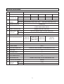
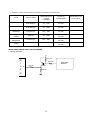
1. SPECIFICATIONS
NO
ITEM
AC 220V/60Hz
AC 127V/50,60Hz
AC 110V/60Hz
AC 220V/50Hz
AC 240V/50Hz
DWF-4220
370W
370W
370W
330W
330W
CONSUMPTION
DWF-5020
430W
430W
430W
370W
370W
MACHINE
DWF-4220 NON PUMP: NET; 30.5kg, GROSS: 35 kg
PUMP: NET; 31.5kg, GROSS; 36kg
WEIGHT
DWF-5020
PUMP: NET; 32.5kg, GROSS; 37kg
1
POWER SOURCE
2
POWER
3
SPECIFICATIONS
NON PUMP: NET; 31.5kg, GROSS: 36 kg
4
DIMENSION (WXHXD)
502X820X500
5
WASHING COURSE
FULL AUTOMATIC 4 COURSES
(FUZZY, SPEED, HEAVY, WOOL)
6
WATER CONSUMPTION
NORMAL 128| (131|: DWF-5020)
7
WATER LEVEL
DWF-4220
HIGH (47|), MEDIUM (38|), LOW (30|), SMALL(22|)
SELECTOR
DWF-5020
HIGH (48|), MEDIUM (39|), LOW (31|), SMALL(23|)
8
OPERATING WATER PRESSURE
0.3~8kgf/cm2 (2.9~78.4N/cm2)
9
REVOLUTION PER MINUTE
10
PULSATOR
11
WATER LEVEL CONTROL
12
OUTER CABINET
13
GEAR MECHANISM ASS'Y
14
LINT FILTER
O
15
SOFTENER INLET
O
16
ALARM SIGNAL
O
17
AUTO WATER SUPPLY
O
18
NEW WATER FLOW
19
FUNCTION FOR BUBBLE
20
MAXIMUM
MASS OF
TEXTILE
SPIN: 750
WASH: 140
SPIN:690 (50Hz)
WASH:130
SPIN: 750 (60Hz)
WASH: 140
SPIN: 750
WASH: 140
SPIN: 690
WASH: 130
5 WINGS (Ø 321mm)
ELECTRONICAL SENSOR
SGCC
PLANETARY GEAR ASSEMBLY OF ENGINEERING PLASTIC
WATER FLOW FOR ADJUST THE UNBALANCED LOAD
OPTION
DWF-4220
4.2 kg
DWF-5020
5.0 kg
2
2. FEATURE AND TECHNICAL EXPLANATION
FEATURE OF THE WASHING MACHINE
1) The first air bubble washing system in the world.
2) Quiet washing through the innovational low-noise design.
3) The wash effectiveness is much more enhanced because of the air bubble washing system.
4) The laundry detergent dissolves well in water because of the air bubble washing system.
5) The adoption of the water currents to adjust the unbalanced load.
6) One-touch operation system.
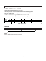
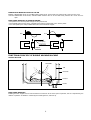
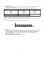
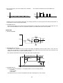
WATER CURRENTS TO ADJUST THE UNBALANCED LOAD
It is a function to prevent eccentricity of the clothes after washing by rotating pulsator C.W and C.C.W for 20 seconds.
C.W
MOTOR
SIGNAL
C.C.W
TIME (SEC.)
0.3
0.5
0.3
0.5
0.3
0.5
20 SEC. (About 13 Times)
WATER FLOW
WASH
I
DRAIN
SPIN
FILL
RINSE 1
I
DRAIN
SPIN
FILL
RINSE 2
NOTE: "I" mark indicates the operation of the water currents to adjust the unbalance load.
EFFECT
It reduces vibration and noise effectively during spinning.
3
I
DRAIN
...
PULSATOR SYSTEM
When the new shaped pulsator is rotated C.W or C.C.W at a high speed, it makes the 'heart-shaped' water currents as
shown below.
C
WATER CURRENTS
A Water is pushed up near the tub
wall by rotation of the pulsator.
Rotate
B Water is pulled down in the middle
of the tub by rotation of the
pulsator
B
A
C Water currents is generated by
rotation of the pulsator.
A
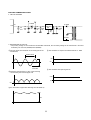
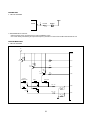
AUTOMATIC DRAINING TIME ADJUSTMENT
This system adjusts the draining time automatically according to the draining condition.
Draining
condition
Good draining
The washer begins spin process after drainage.
Bad draining
Draining time is prolonged.
No draining
Program stops and gives the alarm.
FUNCTIONAL PRINCIPLE
1. The micom can remember the time from the beginning of drain to reset point when the pressure switch reaches to
"OFF" point.
Drain Time
Movement of the Program
Less than 5 minutes
Continue draining.
More than 5 minutes
Program stops and gives the alarm with all lamps of the "COURSE" light up.
2. In case of continuous draining, residual drain time is determined by micom.
Draining time as a whole=D + 60
(T sec.)
Residual drain time.
The time remembered by micom.
(mm)
* 340
TRIP POINTS
280
*
DRAINING
TIME
D4
*
220
D3
T4
*
T3
160
D2
D1
T2
T1
*
*
RESET POINTS
60
*
* 60
0
SMALL
T1=D1+60 (Sec.)
LOW
T2=D2+60 (Sec.)
4
MED
T3=D3+60 (Sec.)
HIGH
T4=D4+60 (Sec.)
WATER
LEVEL
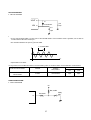
SOFTENER DISPENSER
This is the device to dispense the softener automatically by centrifugal force.
This is installed inside the Balancer Ass'y.
FUNCTIONAL PRINCIPLE
1. Softener stays in room (A) when poured into softener inlet.
2. Softener in moved from (A) to (B) by centrifugal force during intermittent spin process.
3. Softener flows from (B) to (C) during rinse process next to intermittent spin.
4. Softener in moved from (C) to (D) by centrifugal force during second intermittent spin.
After spin process is finished, the softener is added into the tub through softener outlet.
FLOW OF THE SOFTENER
Wash
Normal
Course
Intermittent
Spin
Centrifugal
force
(A)
Hold
Intermittent
Spin
Rinse
Flow in
Centrifugal
force
(D)
Flow in
(B)
(C)
Spin
FLOW OF THE SOFTENER INSIDE OF THE BALANCER
Room inside
the balancer
A
B
C
D
Centrifugal force
Flowing by
weight
NOTE: Softener moves into the next room when r.p.m. of the tub is more than 100 r.p.m.
HOW TO CHECK MOVEMENT
Pour a reasonable amount of "MILK" into softener
dispenser and operate the washer with no load. In final
rinse cycle, make sure that the milk is added into the
tub through softener outlet.
Balancer
B
D
A
Softener inlet
5
C
Softener
outlet
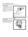
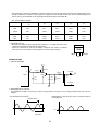
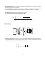
AUTOMATIC UNBALANCE ADJUSTMENT
This system is to prevent abnormal vibration during intermittent spin and spin process.
FUNCTIONAL PRINCIPLE
1. When the door is closed, the safety switch
contact is "ON" position.
2. In case that wash loads get uneven during spin,
the outer tub hits the safety switch due to the
serious vibration, and the spin process is
interrupted.
3. In case that P.C.B. ASS'Y gets "OFF" signal from
the safety switch, spin process are stopped and
rinse process is started automatically by P.C.B.
ASS'Y.
4. If the safety switch is operated due to the
unbalance of the tub, the program is stopped and
the alarm is given.
Contact of safety switch door closing
door opening
Contact lever A
Position of
unbalanced
load(OFF)
Normal(ON)
NOTE:
The alarm finished when you close the door after opening it.
Check the unbalance of the wash load and the installation
condition.
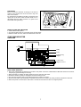
CIRCULATING-WATER COURSE AND LINT FILTER
CIRCULATING-WATER
The washing and rinsing effects have been
improved by adopting the water system in which
water in the tub is circulated in a designed pattern.
When the pulsator rotates during the washing or
rinsing process, the water below the pulsator vane
creates a water currents as shown in figure.
Tub
Filter
Water
channel
Pulsator
6
Outer tub
LINT FILTER
Much lint may be obtained according to the kind of
clothes to be washed and some of the lint may also
stick to the clothes.
To minimize this possibility a lint filter is provided on the
upper part of the tub to filter the wash water as it is
discharged from the water channel. It is good to use
the lint filter during washing.
Bleach inlet
Filter
Pulsator
HOW TO CLEAN THE LINT FILTER
1. Pull the filter frame upward.
2. Turn the lint filter inside out, and wash the lint off with water.
3. Return the filter as it was, and fix the filter frame to the slot.
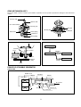
SYNCRONOUS MOTOR
STRUCTURE
Pull
Loosen
Pulley
Lever
Inductive ring
Magent
Coil of motor
Magnet of motor
FUNCTIONAL PRINCIPLE
1. When the SYNCRONOUS MOTOR connected to the power source the SYNCRONOUS MOTOR rotates and revolves
the pulley by gear assembly for reducing.
2. When the pulley is rotated, the pulley winds the wire to open the drain valve.
3. Therefore, rotation of pulley is changed to the linear moving of wire.
4. The wire pulls the brake lever of Gear Mechanism Ass'y within 5 seconds.
5. After the wire pulled, gear assembly is separated from motor and condition of pulling is held by operation of the lever.
6. When the power is turned off, the drain valve is closed because the wire returns to original position.
7
GEAR MECHANISM ASS'Y
The proper water currents is made by the rotation of pulsator at a low speed to prevent the damage to the small sized
clothes.
Pulsator shaft
Spinner shaft
One clutch bearing
Planetary gear
Sun gear
Planetary gear
Internal gear
Clutch spring
Brake lever
Clutch boss
Spinner pulley
Pulsator
Motor
Planetary
V.BELT
1 revolution
Motor
Spinner Pulley
Planetary
gear
1/5.0
Pulsator
5 revolutions
Tub
Spinner
pulley
Directly
V.belt
PRINCIPLE OF BUBBLE GENERATOR
STRUCTURE
Bobbin & coil
Armature
Magnet
Bellows
Trans core
Air
Air
Air out hole
Air in hole
Protector A
Protector B
8
PRINCIPLE OF INTAKE & OUTLET OF THE AIR
INTAKE : ARMATURE moves up, and BELLOWS inhales the air. At the same time, protector B is open and A is close.
OUTLET: ARMATURE moves down, and BELLOWS exhausts the air. At the same time, protector B is close and A is
open.
FUNCTIONAL PRINCIPLE OF TRANS & MAGNET
• The phase of A.C electric power changes to 60 cycle/second.
• The magnetic pole of trans core is changed by the change of the phase of A.C electric power.
• The core repeats push and pull (3600 times/min.) of the armature magnet.
A.C
A.C
N
NS
S
S
Leaf spring
NS
Trans core
N
Magnet
FUNCTIONAL PRINCIPLE OF BUBBLE WASHING MACHINE
ACROSS SECTION
Air bubble
Tub
Outer tub
Pulsator
Nozzle
FUNCTIONAL PRINCIPLE
Bubble generator supplies the air from the bottom of outer tub to the inner space of pulsator, the air is dispersed by the
rotation of pulsator. Air-bubble is created by the centrifugal force, and rises up.
9
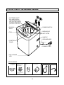
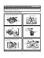
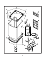
3. STRUCTURE OF THE WASHING MACHINE
• SOFTENER INLET
Pour softener into the
softener inlet just before
wash and it will be added
into the tub automatically
just before the final rinse.
• BLEACH
INLET
• POWER SWITCH
• HOOK HOLE
• TUB
• LINT FILTER
• HANDLE
• GROUND WIRE
• CONTROL
PANEL
• POWER CORD
• ADJUSTABLE
LEG
ACCESSORIES
Drain Hose
Clamp
Drain Hose
Under Base
Cover [Option]
P
U
In case of screw-shaped inlet
hoses water tap adapters will
not be provided.
10
Non-Pump Model
Water Tap Adapter
(COLD)
Water Tap Adapter
(HOT) [Option]
Pump Model
Inlet Hose (COLD)
Inlet Hose
(HOT) [Option]
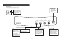
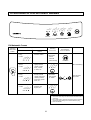
4. FUNCTIONS OF THE CONTROL PANEL
Control Panel
It has micom sensor.
As the buttons are pressed, the lamps indicating the
selection of your desired washing program will light up.
Start/Hold Button
Power Switch
SP
H
SE
IN
AS
R
W
ZZ
SP Y
EE
H DY
EA
V
W Y
O
O
L
FU
H
ED
LO IUM
W
SM
AL
L
IG
M
H
M
LD
O
C
T
AR
O
POWER
W
OFF
• Press this switch to turn
the power ON or OFF.
• After turning off the power,
wait for more than 3
seconds and then turn it
on again.
H
ON
IN
• Press this button to begin
operation or to stop
operation temporarily.
• Operation and temporary
stop are repeated as it is
pressed.
START/HOLD
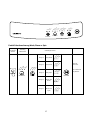
WATER TEMP.
WATER LEVEL
COURSE
PROCESS
[Option]
Temperature Selection
Button
• This button is used to
select the water
temperature according to
the clothes being washed.
• Press this button until your
desired temperature
indicator light comes on,
and it will repeat following
signs:
COLD ¤A WARM ¤A HOT
Water Level Selector
Course Selection Button
Process Selection Button
• This selector is used to select the
washing water level according to
the size of the wash load.
• This button is used to select the
washing course according to
the type of the clothes being
washed.
• You can choose one of the four
courses by pressing this button
until your desired course
indicator light comes on.
• This button is used to select the
desired process of washing.
• If a full cycle of wash, rinse, and
spin is not desired, the desired
process can be selected by
pressing this button until your
desired process indicator light
comes on.
11
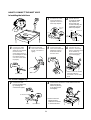
5. DIRECTIONS FOR INSTALLATION AND USE
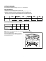
HOW TO INSTALL THE WASHING MACHINE
Selection of the Installing Place
Install the washer on the horizontal solid floor.
If the washer is installed on an unsuitable floor, it could make
considerable noise and vibration.
Never install in these places.
• The place where it would be exposed to direct
sunlight.
• The place nearby a heater or heat appliances.
• The place where it would be supposed to be frozen in
winter.
• The kitchen with coal gas and a damp place like a
bathroom.
• The proper installation of the washing machine can
increase the wash effectiveness and the life of it.
If the washer is installed on an inclined floor, it could make considerable noise
and vibration and could cause a malfunction.
Use the height adjust rubber to adjust the washing machine so that it sits
properly.
How to install on an Inclined Place
1. Height Setting
2. Check the Horizontal Status
• After controlling the height by
turning the adjustable leg, let the
washer put down to the ground.
• Check the position of tub above
the center of the washer.
NOTES:
The opening must not be
obstructed by carpeting when
the washing machine is installed on a carpeted floor.
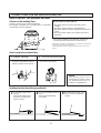
Installing the Drain Hose [Non-pump Model]
case that it goes over a
¡ Indoorsill.
Don't let the height of the
drain hose exceed 20cm
from the gound.
case of extending the drain
careful that the end of the
™ Inhose.
£ Be
drain hose is not immersed
Don't let the total length
exceed 3m.
3m
20Cm
12
in water.
¡
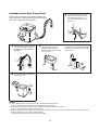
Installing the Drain Hose [Pump Model]
Never forget to install drain hose before operating this
washing machine. The packing box opened, there are a
drain hose, a clamp, and a hose fixture.
the hose guide, included
™ Attach
in the accessory kit, to guide
the drain hose over the tub or
standpipe.
£
Hook the drain hose to the
edge of the tub, paying
attention that there are no
bends or constractions along
the drain hose.
Connect the drain hose to the
drain outlet at the rear side of
the washing machine, and
fasten it tightly with the clamp
supplied.
Or, connect the drain hose to a
standpipe of a diameter greater than
that of the drain hose and at a height
of min. 70cm.
70Cm min
PULL HOSE
THROUGH
55mm
FLEX HOSE
GUIDE
APART
the washing machine
¢ Position
next to the wall.
MUST be
ventilated
NOTES:
1. Let the highest point of the drain hose be more than 1m above the floor.
If not so, the water in the washer could be drained during operation
2. Be sure that the height of the drain hose must be less than 1.5m above the floor.
If not so, the water in the washer could not drain.
3. The hose guide MUST be fitted to the drain hose. The drain hose sould not extend more than 55mm from the end of
the hose guide. This is to prevent ‘SYPHONING’.
If necessary the drain hose can be trimmed to length.
13
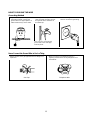
HOW TO CONNECT THE INLET HOSE
In Installing the Inlet Hose
¡
Pull down the collar
of the inlet hose to
separate it from the
water tap adapter.
™
Water Tap
Adapter
Loosen the four
screw at the water
tap adapter, but
don't loosen the
screws until they are
separated from the
water tap adapter.
Tape
Collar
Connector A
Rubber
packing
Tap
Adapter
Connector B
Connector C
£
Connect the water
tap adapter to the
water tap, and tighten
the four screws
evenly while pushing
up the adapter so that
the rubber packing
can stick to the water
tap tightly.
¢
∞
Remove the tape,
and screw connector
B into connector A
tightly.
Connect the inlet
hose to the water tap
adapter by pulling
down the collar of
the hose end.
§
Connect the connector C of the inlet
hose to the water inlet
of the washer by
turning it clock-wise
to be fixed tightly.
@
!
• Please check the rubber
packing inside the
connector C of the inlet
hose.
Connector B
For Screw-Shaped Tap
¶
™
Connect the inlet
hose to the water tap
by screwing the
connector D tightly.
Connector D
Hose
Connect the connector C of the inlet hose to the
water inlet of the
washer by turning
it clockwise to be
fixed tightly.
Rubber
Packing
• Please check the
rubber packing
inside the connector
C of the inlet hose.
Connector C
14
HOW TO GROUND THE WIRE
Grounding Method
• If your water tap or water pipe is
not made of metal, connect the
ground wire to a copper plate or a
metal rod and bury it in the earth.
20Cm
• If both your water tap and water
pipe are made of metal, connect
the ground wire to the base of
the water tap.
• In case of using 3-core cord,
there is no need for grounding.
* It is of no use connecting the
ground wire to the water pipe
made of plastic.
Never Connect the Ground Wire to Such a Thing
• Never connect it to a gas pipe because of danger of a
explosion.
• Never connect it to a telephone wire or a
lightning rod because it is very dangerous at a
thunderbolt.
Gas Pipe
Telephone Wire
15
W
AS
R H
IN
S
SP E
IN
ZZ
SP Y
EE
H DY
EA
V
W Y
O
O
L
FU
M
H
H
O
T
W
AR
C M
O
LD
IG
H
ED
LO IUM
W
SM
AL
L
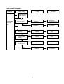
6. PROCEDURE OF FULL-AUTOMATIC WASHING
START/HOLD
WATER LEVEL
WATER TEMP.
COURSE
PROCESS
Full Automatic Course
Selecting Course
FU
IG
Lightly stained
clothes: underwear, T-shirts,
Y-shirts, etc..
Procedure to
Press the Button
START/HOLD
H
ED
LO IUM
W
SM
AL
L
• The Water
level is
selected
automatically
H
Speed
Course
General clothes
FU
ZZ
SP Y
EE
H DY
EA
V
W Y
O
O
L
Fuzzy
Course
Selecting
Water level
Kinds of the
Clothes
End of Washing
M
Course
ZZ
SP Y
EE
H DY
EA
V
W Y
O
O
L
Pressing
the Power
Switch
POWER
It is informed
by buzzer.
ED
M
IG
LO IUM
W
SM
AL
L
COURSE WATER LEVEL START/HOLD
H
Delicate clothes:
Sweater, silk,
lingerie, etc.
• The Water
level is fixed
to "HIGH"
FU
ZZ
SP Y
EE
H DY
EA
V
W Y
O
O
L
Wool
Course
Heavily stained
clothes: blue-jean,
climbing clothes,
ruck-sack, sports
wear, etc..
H
FU
ZZ
SP Y
EE
H DY
EA
V
W Y
O
O
L
Heavy
Course
After Operation is finished
• Close the water tap, and disconnect the inlet hose if
necessary.
• Turn off the power, and disconnect the power cord from
the electric outlet, being sure to take hold of the plug.
• Clean the lint filter.
16
W
AS
R H
IN
S
SP E
IN
ZZ
SP Y
EE
H DY
EA
V
W Y
O
O
L
FU
IG
H
ED
LO IUM
W
SM
AL
L
M
H
O
T
W
AR
C M
O
LD
H
START/HOLD
WATER TEMP.
COURSE
WATER LEVEL
PROCESS
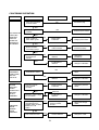
Partial Selections Among Wash, Rinse or Spin
Selecting
Water level
IN
SP
IN
SP
H
IN
R
IN
R
AS
AS
H
IN
S
SP E
IN
W
End of
Process
IN
IN
It is informed
by buzzer.
SP
Only Spin
R
Stage 3
W
AS
H
R
W
IG
H
M
H
ED
LO IUM
W
SM
AL
L
H
Only Rinse
SE
Stage 2
AS
Only Wash
W
Stage 1
SE
Selecting Process
SE
Pressing
the Power
Switch
POWER
START/HOLD
Wash and
Rinse
Stage 5
Rinse and
Spin
17
AS
R H
IN
S
SP E
IN
Stage 4
W
AS
R H
IN
S
SP E
IN
PROCESS
W
WATER LEVEL
7. DIRECTIONS FOR DISASSEMBLY AND ADJUSTMENT
WARNING
BEFORE ATTEMPTING TO SERVICE OR ADJUST ANY PART OF THE WASHING MACHINE, DISCONNECT THE
POWER CORD FROM THE ELECTRIC OUTLET.
GEAR MECHANISM ASS'Y REPLACEMENT
• Raise the top plate on the outer cabinet.
• Loosen four screws mounting outer tub cover and
remove outer tub cover from the tub ass'y
• Loosen the pulsator mounting screw and remove
pulsator.
Pulsator Mounting screw
Outer tub cover
Mounting
screw
• Remove the special Nut by using 'T' type box wrench.
• Remove the special washer.
"T" type box
wrench
• Remove the tub ass'y.
Special
Washer
Pulsator
Special Nut
Special Nut
Special Washer
Tub ass'y
• Lay the front of the washer on the floor.
• Remove four bolts mounting the gear protect by
using a box wrench and remove gear protect.
• Remove the V-belt.
• Remove four bolts mounting the gear mechanism
ass'y by using a box wrench.
• Pull out the gear machanism ass'y.
Gear Mechanism
Ass'y
Mounting bolt
Mounting bolt
NOTE: To assemble the gear mechanism ass'y, reverse the disassembly procedure.
18
SYNCRONOUS MOTOR AND VALVE REPLACEMENT
• Lay the front of the washer on the floor.
• Loosen the adjustment screw and three bolts
mounting the drain motor.
• Take out the wire of syncronous motor from the
bracket.
• Separate the syncronous motor from the bracket.
• Turn the valve lid by using screw driver as shown in
figure and remove the valve lid from the valve frame.
Valve frame
Wire
Bracket
Bracket
Adjustment
screw
Adjustment
screw
Pole
Screw driver
Syncronous motor
Valve lid Pole
Valve
packing
Valve lid
BRAKE ADJUSTMENT
• Loosen the adjustment screw fastening the bracket
and place the adjustment screw to the brake lever
as shown in figure.
• Tighten the adjustment screw completely.
• Loosen the adjustment bolt and turn the adjustment
bolt until the end of the bolt touches to the b rake
lever.
• Tighten the lock nut and apply a small amount of
paint-lock.
Adjustment bolt
Brake lever
3mm
Gear mechanism ass'y
Brake lever
Adjustment screw
Clutch lever
NOTE:
1. The brake adjustment has been made at the factory, so that it is not to re-adjust. However, in case of insufficient
brake operation, perform the upper procedure.
2. Overtightening of the adjustment bolt will cause poor brake performance.
3. Undertightening of the adjustment bolt will cause continuous bracking and, thereby, cause the problems of the
motor during the spin cycle.
19
8. TROUBLE SHOOTING GUIDE
NOTE:
1. When you replace the P.C.B. ASS'Y do not scratch the surface of the P.C.B. ASS'Y.
2. Disconnect the power cord from the electric outlet.
CONCERNING WATER SUPPLY
PROBLEM
CHECK POINT
CAUSE
Do you open the
Water tap?
NO
SOLUTION
Open the water
tap.
YES
Is the filter of the
water inlet valve
clogged with dirt?
YES
Clean the filter.
NO
Is the water pressure
sufficient?
2
(0.3~8 kgf/cm )
NO
Increase the water
pressure.
NOTE: Open the water tap fully and measure the flow rate.
WATER IS
NOT
SUPPLIED
YES
Flow
rate (l /min)
11.5
15.0
18.0
20.3
24.1
27.4
Water pressure
(kgf/cm2 )
0.3
0.4
0.5
0.6
0.8
1.0
From the upper results, you know that the flow rate more than
11.5l/min. is essential for water supply.
Does the water inlet
valve make operating
sound?
YES
Water inlet valve
is defective.
Change water inlet
valve.
NO
Is the connector or
the terminal connected
properly?
NO
Improper connection
of the connector or
the terminal
Connect the connector
or the terminal
properly.
NO
P.C.B ASS'Y is
defective.
Change the P.C.B AS.
Lead wire is defective.
Change the lead wires.
YES
Is the output voltage
of the P.C.B normal?
YES
20
PROBLEM
CHECK POINT
CAUSE
NO
Is the plug connected
to electric outlet?
SOLUTION
Connect the plug.
YES
NO
Is the power switch
pressed?
THE INDICATOR
LAMP (LED)
DOES NOT
LIGHT UP
WHEN THE
POWER S/W
IS PRESSED.
Press the power switch.
YES
Is the condition of
power switch good?
NO
Power switch
is defective.
Change power switch.
NO
Improper connection
of the connector.
Connect the
connector properly.
NO
Transformer is
defective.
Change the
transformer.
P.C.B ASS'Y is
defective.
Change P.C.B ASS'Y.
YES
Is the connector of
the P.C.B. ASS'Y
connected properly?
YES
Is output voltage of
the transformer
normal?
YES
CONCERNING WASHING
PROGRESS
LAMPS (LED)
DO NOT
LIGHT UP.
MOTOR
ROTATES
WHEN
START/HOLD
BUTTON
IS NOT
PRESSED.
ABNORMAL
NOISE
DURING
WASH
PROCESS
NO
Do you press
START/HOLD button?
Does the pressure
switch operate
normally?
YES
P.C.B ASS.Y is
defective.
Change P.C.B ASS'Y.
NO
Pressure switch
is defective.
Change the pressure
switch.
Abnormal
YES
Check the output voltage
of P.C.B ASS'Y.
Is the strange noise
generated when the
pulsator rotates in TEST
MODE of P.C.B
ASS'Y.
Press START/HOLD
button.
P.C.B ASS.Y is
defective.
YES
Change P.C.B ASS'Y
There is foreign matter
between pulsator
and tub.
Remove the foreign
matter.
V-belt is defective.
Change the V-belt.
NO
YES
Is the V-belt worn out?
21
CONCERNING DRAINING
PROBLEM
CHECK POINT
CAUSE
YES
Is the door open?
SOLUTION
Close the lid.
NO
Does the safety switch
operate normally?
THE WASHER
DOES NOT
DRAIN.
NO
Safety switch is
defective.
NO
Improper connection
of the connector
Connect the connector
properly.
P.C.B ASS'Y is
defective.
Change P.C.B ASS'Y.
Improper installation
Install drain hose
properly.
Drain problem by the
foreign matter
accumulated inside
drain valve housing.
Remove the foreign
matter.
Change the safety
switch.
YES
Is the connector
of P.C.B ASS'Y
connectsd properly?
YES
Do you put down
the drain hose?
NO
YES
Does the syncronous
motor operate
normally?
YES
NO
YES
Is the input
voltage of syncronous
motor normal?
NO
22
Syncronous motor is
defective.
Change the syncronous
motor.
P.C.B ASS'Y is
defective.
Change the P.C.B
ASS'Y.
CONCERNING SPINNING
PROBLEM
CHECK POINT
CAUSE
SOLUTION
Does the pulsator
rotate while the tub
does not rotate?
NO
THE WASHER
DOES NOT
SPIN.
YES
Is the input voltage
of the drain motor
normal?
YES
NO
Is the V-belt
worn out?
YES
Syncronous motor
is defective.
Change the
Syncronous motor.
P.C. B ASS'Y
is defective.
Change the
P.C.B ASS'Y.
V-belt is
defective.
Change the
V-belt.
YES
Motor is
defective.
Change the
motor.
NO
Improper
connection.
NO
Is the input
voltage of motor
normal?
NO
Is the connection
condition of capacitor
terminal good?
YES
P.C.B ASS'Y
is defective.
23
Connect the
terminal correctly.
Change the
P.C.B ASS'Y.
CONCERNING OPERATION
PROBLEM
CHECK POINT
CAUSE
NO
Is the plug connected
to electric outlet?
SOLUTION
Connect the plug.
YES
NO
Is the power switch
pressed?
THE INDICATOR
LAMP (LED)
DOES NOT
LIGHT UP
WHEN THE
POWER S/W
IS PRESSED.
Press the power switch.
YES
Is the condition of
power switch good?
NO
Power switch
is defective.
Change power switch.
NO
Improper connection
of the connector.
Connect the
connector properly.
NO
Transformer is
defective.
Change the
transformer.
P.C.B ASS'Y is
defective.
Change P.C.B ASS'Y.
YES
Is the connector of
the P.C.B. ASS'Y
connected properly?
YES
Is output voltage of
the transformer
normal?
YES
PROGRESS
LAMPS (LED)
DO NOT
LIGHT UP.
MOTOR
ROTATES
WHEN
START/HOLD
BUTTON
IS NOT
PRESSED.
ABNORMAL
NOISE
DURING
WASH
PROCESS
NO
Do you press
START/HOLD button?
Does the pressure
switch operate
normally?
YES
P.C.B ASS.Y is
defective.
Change P.C.B ASS'Y.
NO
Pressure switch
is defective.
Change the pressure
switch.
Abnormal
YES
Check the output voltage
of P.C.B ASS'Y.
Is the strange noise
generated when the
pulsator rotates in TEST
MODE of P.C.B
ASS'Y.
Press START/HOLD
button.
P.C.B ASS.Y is
defective.
YES
Change P.C.B ASS'Y
There is foreign matter
between pulsator
and tub.
Remove the foreign
matter.
V-belt is defective.
Change the V-belt.
NO
YES
Is the V-belt worn out?
24
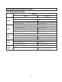
9. PRESENTATION OF THE P.C.B ASS'Y
CONCERNING ERROR MESSAGE
MESSAGE
CAUSE
ƒoƒoƒo
DRAINAGE
ERROR
LEVEL
SENSING
ERROR
ƒoƒoƒo
The drain hose is blocked up by foreign matter.
Remove foreign matter from drain hose.
Drain motor is inferior.
Change drain motor.
ƒoƒoƒoƒo
§§§§
§§§
The water tap is closed.
Open the water tap.
The water inlet filter clogged.
Clean the water inlet filter.
It passes over the 30 minutes, yet it doesn't
come to assigned water level.
Check whether or not it comes to the
assigned water level.
§§§§
ƒoƒoƒoƒo
ƒoƒoƒo
Wash loads get uneven during spin.
Re-set wash loads evenly.
Poor installation of the unit.
Install properly.
ƒoƒoƒo
DOOR
OPEN
ERROR
§§§§
Install drain hose properly.
ƒoƒoƒo
UNBLANCE
ERROR
ƒoƒoƒoƒo
Improper installation of drain hose.
ƒoƒoƒo
INLET
ERROR
SOLUTION
ƒoƒoƒoƒo
ƒoƒoƒoƒo
§§§
The door is opened.
Close the door.
The safety switch is inferior.
Change the safety switch.
ƒoƒoƒo
§§§§
The water level sensing is inferior.
ƒoƒoƒoƒo
§§§
Check the water level sensor and the
contact parts of the connector.
25
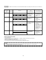
TEST MODE
The operation condition of the washer can be checked without water in the tub by test mode of the P.C.B. ASS'Y as
shown below.
No. of times
to press
button
'Water Level'
0
1
Check
Mode
A
B
2
C
3
D
DISPLAY
§
ƒo
§
ƒo
§
ƒo
§
ƒo
§
ƒo
§
ƒo
§
ƒo
§
§
§
ƒo
Items
being checked
§
ƒo
§
ƒo
§
§
§
ƒo
§
ƒo
ƒo
ƒo
ƒo
ƒo
ƒo
ƒo
ƒo
§
ƒo
ƒo
ƒo
§
§
§
ƒo
ƒo
ƒo
ƒo
ƒo
ƒo
ƒo
§
ƒo
ƒo
ƒo
§
§
§
The condition of
normal operation
• Buzzer sound
indicating the end
of washing
• L.E.D lamp
• The buzzer sound
8 times while the
indicator lights
blinks
• The condition of
wash process
(Motor)
• The pulsator
rotates
continuously
without water in
the tub
• The functional
condition of whole
operating
• The washer
repeates following
operating
Drain ¤ASpin ¤A
Cold Water ¤AHot
Water ¤APulsator
rotate (right) ¤A
Bubble ¤APulsator
rotate (left) ¤A
Pump¤ADoor check
¤AINITIAL STATE
• Aging Mode for
P.C.B. ASS'Y
• C Mode runs
continously
without INITIAL
STATE
HOW TO OPERATE TEST MODE
1. Turn off the power.
2. Keep pressing two buttons ('WATER LEVEL', 'COURSE'.) together and press the power switch.
3. Remove your fingers on the two buttons.
4. Press the 'WATER LEVEL' button according to desired check mode.
5. It is possible to stop operation temporarily by pressing 'START/HOLD' button.
NOTE:
• If pressing 'PROCESS' button within 10 seconds, the check mode changes to 'B', 'C' and 'D' mode.
• If 'PROCESS' button is not pressed, 'A' mode will run.
26
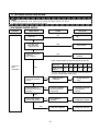
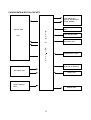
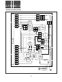
CONFIGURATION OF FULL CIRCUITS
LOAD DRIVE UNIT
(MOTOR, WATER INLET,
DRAIN, BUBBLE)
WATER LEVEL SENSOR
UNIT
DISPLAY UNIT
L.E.D
M
I
C
O
M
I.C
LOAD SENSOR UNIT
INTERRUPT UNIT
D
W
F
4
2
2
0
POWER SUPPLY UNIT
MAIN OSC (4.1943MHz)
KEY INPUT UNIT
RESET UNIT
SAFETY SWITCH
UNIT
BUZZER UNIT
27
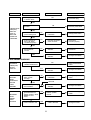
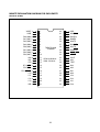
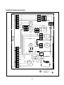
MINUTE EXPLANATION DIAGRAM FOR EACH PARTS
MICOM IC (42 DIP)
VAREF
1
42
VDD
VASS
2
41
R92(SCK)
R40 (AIN0)
3
40
R91(SO)
R41 (AIN1)
4
39
R90(SI)
R42 (AIN2)
5
38
R83(T1)
R43 (AIN3)
6
37
R82(INT1)
R50 (AIN4)
7
36
R81(T2)
R51 (AIN5)
8
35
R80(INT2)
R52 (AIN6)
9
34
HOLD(KEO)
R53 (AIN7)
10
33
RESET
R60
11
32
XOUT
R61
12
31
XIN
R70
13
30
TEST
R71 (WTO)
14
29
K03
R72 (XTIN)
15
28
K02
R73 (XTOUT)
16
27
K01
P10
17
26
K00
P11
18
25
P23
P12
19
24
P22
P13
20
23
P21
VSS
21
22
P20
TMP47C 840N
TOSHIBA
ROM: 8192X8 bit
RAM: 512X4 bit
28
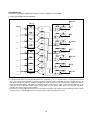
LOAD DRIVE UNIT
(CW WASH, CCW WASH, DRAINAGE, BUBBLE, PUMP, HOT WATER, COLD WATER)
1. CIRCUIT DIAGRAM AND EXPLANATION
1 BL/YW
RA1
R1
C1
683k
100 1W
R67
10K
3.3K
R51
10
SM12JZ47
Q8
A1270
R21
C2
104Z
62
R1/2W
R69
10K
3.3K
R53
9
R2
R52
8
10K
3.3K
C4
104Z
R5
Q11
A1270
R19
R50
7
10K
3.3K
R4
10K
3.3K
R73
5
10K
3.3K
4
10K
3.3K
R75
3
3.3K
10K
5 PK
TRIAC4
C5
103k
100 1W
SM3JZ47
Q13
A1270
R10
C6
104Z
R6
Q14
A1271
R10
C11
223k
SM3JZ47
C12
104Z
R7
Q15
A1270
7 YW
TRIAC6
C13
273k
100 1W
SM3JZ47
RA2
6 BL/WH
TRIAC5
100 1W
62
R1/2W
R40
103k
SM3JZ47
R3
62
R1/2W
R74
R41
C7
BCR1AN
Q12
A1270
R12
4 YW/BK
TRIAC3
C8
104Z
62
R1/2W
R42
103k
100 1W
R72
6
C9
C10
104Z
Q10
A1270
R13
3 BL
TRIAC2
BCR1AN
330
R43
683k
100 1W
330
R70
C3
SM12JZ47
62
R1/2W
R71
TRIAC1
100 1W
Q9
A1270
R20
2 VT
8 RD/BL
C14
104Z
• Controlling load of button input in MICOM terminal, it is selected to 'H' or 'L'. It is selected to 'L' in running load case and
in 'H' case, load driving is finished. In clockwise rotation of washing motor, as MICOM No. 10 is changed 6V to 0V, TR
(Q8, A1270Y) is turn on. And then, the TRIAC1 (SM12JZ47) is turn on, the source of electric power is supplyed to washing
motor for clockwise rotation. The TRIAC, as switching element, force to 'ON' or 'OFF' by use of the Q8 (A1270Y). In the
rest loads, when the MICOM terminal voltage changes 6V to 0V, each TRIAC DRIVE TR is active, and then the TRIAC
switches the source of electric power to loads.
• The purpose of using the MICOM terminal No.3 Q15 (A1271Y) is that the Q15 prevents the instant supply of electric power
supply to loads, in case MICOM's action is wrong by means of pushing initial power switch.
29
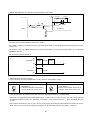
2. DETAIL EXPLANATION OF CIRCUIT ACTION (ACTION OF CW WASH)
6V
C1 683K
C2
104Z
10K
10
R1 100 1W
TRC1 SM12JZ47
R67 3.9K
Q8 A1270Y
MICOM
AC COMMON +6V
R21 62 1/2W
•In case MICOM TERMINAL No. 10 is 'L', the Q8 (A1270Y) turn on and control the TRIAC. The resistance, as 62Ω & 1/2W,
of the R21 is used to limit the GATE current of the TRIAC.
•The ceramic condenser C2 between the T1 and the GATE of the TRIAC is used for preventing the wrong action by means
of the noise.
•The R1 (100Ω, 1W) and C1 (683K) between the T1 and T2 of the TRIAC is used for protecting the TRIAC, it is usually called
SNUBBER CIRCUIT.
•The waveform of MICOM pin No. 1
6V
Terminal No. 10
STOP
ACTION
STOP
t
0V
6V
Terminal No. 3
ACTION
t
0V
3. CAUTION AND CHECKING FOR A/S
• If load is active as soon as the power switch is ‘ON’, check the driving TRIAC of load.
SM12JZ47 (12A), SM8JZ47 (8A) SM3J247 (3A)
shape
BCR1AM-12L
shape
• CHECK the resistance of the T1 & T2
of the TRIAC. (∞Ω).
• CHECK the total parts without fail, in
case the TRIAC has a short circuit.
• CHECK the resistance of the T1 & T2
of the TRIAC. (∞Ω).
• CHECK the total parts without fail, in
case the TRIAC has a short circuit.
T1 G T2
T1 T2 G
• Check the MICOM output terminal, if the load doesn't act although the TRIAC isn't anything wrong.
• Sometimes it is happened that the TRIAC DRIVE TR has a short circuit or an open circuit. In this case, being measured
the resistance between the TR E & C with tester, the resistance value should be near the ∞Ω. If not, the DRIVE TR is out
of order.
• If the ceramic condenser (C2, C4, C6, C8, C10, C12, C14) using by protecting the noise between the GATE & T1 of each
TRIAC has a short circuit, it has no voltage drop between the T1 and GATE. Therefore, the TRIAC is not turn on.
30
• The TRIAC's names and the values of the snubber & resistance of the total parts.
LOAD
TRIAC’S NAME
GATE’S
RESISTANCES OF
LIMITED
CURRENTS
CW WASH
SM12JZ47
BCR 12PM-14L
62Ω, 1/2W
100Ω, 1W+683K
AC 250V
CCW WASH
SM12JZ47
BCR12PM-14L
62Ω, 1/2W
100Ω, 1W+683K
AC 250V
DRAINAGE
BCR1AM-12L
330Ω, 1/4W
100Ω, 1W+103K
AC 250V
HOT/COLD
WATER
SM3JZ47
62Ω, 1/2W
100Ω, 1/W+223K
AC 250V
BUBBLE
GENERATOR
BCR1AM-12L
330Ω, 1/4W
100Ω, 1W+103K
AC 250V
SM8JZ47
62Ω, 1/4W
PUMP
VALUES OF
THE SNUBBER
100Ω, 1W+103K
AC 250V
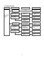
WATER LEVEL SENSOR UNIT1. CIRCUIT DIAGRAM
1. CIRCUIT DIAGRAM
M
I
C
O
M
R61, 10K
R52, 3.9K
R48, 220
38
Q3
A1270Y
R49 10K
31
PRESSURE
SENSOR
RESISTANCES OF
TOTAL PARTS
2. EXPLANATION OF CIRCUIT
• Push the power switch. And, in order to carry on the action of course selection, input the selection of frequency
according to each water level selection.
• The frequency of water level sensor in each water level becomes square wave and is sended to the MICOM.
WATER LEVEL NAME
FREQUENCY
WATER LEVEL
HIGH
MIDDLE
LOW
SMALL
23.0 kHz
23.5 kHz
24.0 kHz
24.4 kHz
450 ± 15
380 ± 15
300 ± 15
240 ± 15
RESET
25.30 kHz
OVER FLOW
22.75 kHz
If the water level is selected ‘HIGH’ in washing, water supply proceeds until inputing the frequency 23.0 KHz of ‘HIGH’ in the
MICOM terminal No. 38. Being finished the water supply, washing process is proceeded.
After the washing process, water level reaches to RESET point, and then after the (D)+ 60 seconds, the spin process
begins.
• The value of the frequency between the MICOM terminal No. 38and the GND.
5.4V
0V
KHZ
f = 22 ~ 25 KHZ
3. CAUTION FOR A/S
• The output of the frequency in the WATER LEVEL SENSOR varies in accordance with temperature and using condition.
If it doesn't input the output of the WATER LEVEL SENSOR in the MICOM, the error message is displayed as
'LEVEL SENSING ERROR' (See page26). In case of proceeding the water supply continuously in 'HIGH' water level, it is
desirable to change the WATER LEVEL SENSOR because of the defect in the WATER LEVEL SENSOR.
• Check the TR Q4 (A1270Y)
• Being checked with tester, the value of the voltage reaches about 4V.
• As the frequency is lower, the water level is higher.
32
ELECTRIC POWER SUPPLY UNIT
1. CIRCUIT DIAGRAM
D5 IN4003
42
Vdd
C29
104Z
C22 +
104Z
470uF
– 50V
16V
IC1
REGULATOR
C28
7806
104Z
C27
50V
104Z
50V
C25
470uF
16V
D3 1N4003
+
C26
1000uF
– 35V
D2 1N4003
2. EXPLANATION OF CIRCUIT
• The primary voitage of the transformer sets RATING VOLTAGE, the secondary voltage of the transformer is full wave
rectified by use of the D2 (1N4003) & D3 (1N4003)
$ The waveform of output in the REGULATOR I.C. 7806.
! The gray & red (The waveform in secondary part of the
transformer)
f=50Hz or 60 Hz
6V
0V
Vpeak=11.4V
Vrms=8V
% The waveform after passing the D5.
@ Measuring the waveform in case of the removing
condenser by the removal ripple C26.
5.4V
0V
0V
# It is removed the ripple with attaching the C26 (1000¥F).
12V
33
• The Electrolytic condenser C22(1000µF, 16V) and diode D5 is used in order that at instant power supply failure circuit
should remember the contents of the program. It happens that the MICOM terminal No. 42 has instant interruption of
electric power, yet the MICOM is not discharged electricity because of the diode D5.
• The measurement of voltage
EFFECTIVE VALUE
!
@
#
$
%
82.5V
5.2V
7.9V
7.9V
5.97V
5.4V
119V
7.2V
11V
11V
5.97V
5.4V
137.5V
9.3V
14.1V
14.1V
5.98V
5.4V
165V
5.3V
7.6V
7.6V
5.96V
5.4V
220V
7.6V
10.6V
10.6
5.98V
5.4V
275V
9.7V
13.7V
13.7V
5.98V
5.4V
3. CAUTION FOR A/S
• Measure the voltage of input terminal REGULATOR I. C. of 7806 with tester. And,
compare the measuring value with the voltage table.
• Check the condenser in case the electrolytic condenser and ceramic condenser
have short circuit. The reason is that it happerns no electric power supply.
7806
INPUT
OUTPUT
GND
INTERRUPT UNIT
1. CIRCUIT DIAGRAM
R50 3.9K
R47 220
37
R60 10K
Q6
C3202
MICOM
C21
103Z
D1 1N4003
@
C24
103Z
!
R61 22K
D4 1N4003
2. EXPLANATION OF CIRCUIT
The INTERRUPT UNIT is necessary to reduce the generation of surge, by use of being voitage ‘ON’ from the zero
voltage.
•The waveform of the part !
•Thewaveform of the part @ (in case of cutting the part of
the dotted line)
f=50Hz or 60 Hz
0V
Vpeak=11.4V
Vrms=8V
34
• After connecting the part of the dotted line & waveform
measurement
• The waveform measurement in the MICOM No.37.
5.4V
0V
0V
The waveform of the secondary part in transformer passes through the diode D1,D4 (1N4003), and then the voltage is
divided by means of the resistance R60 & R61. This voltage gives force to input the pulse to the MICOM terminal No. 37
on the ground of action of the TR Q6 (C3202Y).
3. CAUTION FOR A/S
• When the phenomenon of no electric power supply happens, to begin with check the electric power supply unit, and
then check the INTERRUPT UNIT. It is desirable to measure Q7 (C3202Y) with tester and C21 (C103Z).
RESET UNIT
1. CIRCUIT DIAGRAM
R38 10K
!
IC2
R37 220
MICOM
33
C19
104Z
C20 +
47uF
–
16V
RESET I.C
S-8054HN
D5 1N4003
+
C22
– 470uF
16V
2. EXPLANATION OF CIRCUIT
• The RESET unit is a hardware circuit, of which all programs are initialized, when the power switch is 'ON'. Here, the
reason why uses RESET I.C. is that the RESET UNIT prevents the MICOM from incorrect action. Also, the R37 & C19
(104Z), as a RC filter, is used in order to absorb the noise.
• The waveform measurement of the part ! with being 'ON' the power switch.
190 msec
4.9V
RESET TIME
500 msec
POWER OFF
5.4V
POWER SWITCH ON
3. CAUTION FOR A/S
• Check the output of the RESET I. C. and judge whether or not it is something wrong.
1. OUTPUT
2. INPUT (VDD)
3. GROUND
• The R38 and C20 turn on the accurate RESET value with controlling the RC time constant.
35
BUZZER UNIT
1. CIRCUIT DIAGRAM
6V
MICOM
R57 220
20
BUZZER
2. EXPLANATION OF CIRCUIT
• After the button action and total process ends, BUZZER is active.
• It is active directly with offering an output the frequency waveform of 2 KHz from the MICOM terminal NO. 20.
BUTTON INPUT UNIT
1. CIRCUIT DIAGRAM
+6V
34 HOLD
R53
10K
R54
Q4
A1270
17 P10
3.9K
R56
10K
R55
Q5
A1270
18 P11
3.9K
Q7
R62
10K
R63
A1270
11 R60
3.9K
WATER
TEMPERATURE
D10
MENU
D6
STOP/START
D7
R36 220
LEVEL
39 R90
COURSE
R22 10K
D9
D8
R35
220
40 R91
R23 10K
36
OSCILLATION UNIT
1. CIRCUIT DIAGRAM
XOUT
XIN
32
X1
C18
4.194304 MHz
31
33pF
C17
33pF
2. EXPLANATION OF CIRCUIT
• As the OSCILLATION UNIT is a basic part of the MICOM DRIVE. If the oscillation doesn’t generate, we are able to
consider that the MICOM is destroyed.
• The waveform between the part of ! and the GND.
f = 4.194304 MHz
t
• Specification of oscillator
It is in general use for the MICOM maker's recommendatory value of condenser which is fit for MICOM's characteristics.
TYPE OF OSCILLATOR
MAKER
CRYSTAL
OSCILLATOR
SUNNY
C17
C18
4.194304MHz
33pF
33pF
SAFETY SWITCH UNIT
1. CIRCUIT DIAGRAM
6V
R26, 3.9KΩ
R33, 220Ω
13
37
CONDENSER
RATING
FREQUENCY
Safety
S/W
2. EXPLANATION OF CIRCUIT
• The MICOM terminal No. 13 gets into 'L' at the state of the closed door. If the door is opened in spining stage, the
MICOM generates error signal. (See page 27)
• Case of range 40 mSEC~300 mSEC in spining time: It is regarded that washing clothes should be inclined.
Accordingly washing time increases 8 minutes and rinsing action takes place another one time. Case of above 400
mSEC: It is regarded that the door should be open. Therefore it is displayed as door open error. (See page 27)
3. CAUTION FOR A/S
• Be level with the ground.
• The UNBLANCE error occurs in case of not being level with the ground.
• The waveform between the MICOM terminal No. 13 and the GND.
5.4V
Door is closed
Door is open
0V
t
LOAD SENSOR UNIT
1. CIRCUIT DIAGRAM
6V
R25, 220
M
I
C
O
M
6V
!
4
2
R15, 10K
36
R16,10K
Q1
R24, 220 A1270
Q2
35
C3202
C16
R17
10K
D11
R14, 10K
R18
3.9K
104Z
!
1N4148
3
PC817
IC3
2. EXPLANATION OF CIRCUIT
• Detecting the voltage of running condenser, it sends the sensing data to the MICOM terminal No.35 & 36. That is, as
charging & discharging time of running condenser becomes different according to the loads, in fuzzy course the
washing time is determined by sensing the quantity of washing clothes.
• The waveform between the part of ! and the GND (waveform of pulse)
6V
0V
t
38
DISPLAY UNIT
1. CIRCUIT DIAGRAM
+6V
34 HOLD
R53
10K
R54
Q4
A1270
17 P10
3.9K
R56
10K
R55
Q5
A1270
18 P11
3.9K
R62
10K
R63
Q7
A1270
HOT
HI
11 R60
3.9K
STANDARD
R66 220
22 P20
WARM
MED
SPEED
R9 220
23 P21
COLD
LOW
DIRTY
R64 220
24 P22
DHY
MIN
DRY/WOOL
R58 220
25 P23
RINSE
WASH
R34 220
19 P12
• When electric power source is turned on, the LED lamp is turned on necessarily corresponding to the standard
course.
39
EARTH
1
RD/BL
RD/BL
3
2
PK
WH/RD
WH
WH POWER
SWITCH
WH
WH/RD
WH/RD
PK
7
6
5
4
HOT
W/S
VALVE
7
6
5
4
WH/RD LINE FILTER
COLD
W/S
VALVE
3
YK
2
GN/YW OR GN
2
1
BL/YW
BL/YW
FUSE
BK
BR OR BK
BN/YW OR GN
BL OR WH
YW/BK
YW
VT
2
2
1
9
8
1
2
DRAIN
PUMP
1
2
BUBBLE
WH GENERATOR
PK
9
1
1
WH/RD
WH/RD
SYNC.
MOTOR
2
2
BL/WH
WH/RD
MOTOR
2
1
YW/BK
2
VT
1
3
3
BL
VT
BL
VT
2
1
VT
BL
SAFETY
SWITCH
2
1
BL/YW
WH/RD
WH/RD
CONDENSER
BL/YW
BL
2
2
1
1
6
5
4
3
2
1
WATER
LEVEL
SWITCH
6
5
4
3
2
1
BK/WH
8
FUSE
BL
1
BL/WH
2
1
BL/WH
1
FUSE
WH/RD
2
1
GN/WH
WH/RD
GN/WH
2
1
BL
BL/YW
BL/YW
YW/BK
BR
2
1
TRANS P.C.B
BL
VT
WH
BL/YW
GY
2
1
GY
RD
3
3
OR
OR
RD
40
WH
P.C.B.
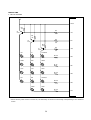
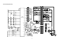
APPEND I X
WIRING DIAGRAM [PUMP]
1
RD/BL
RD/BL
3
2
PK
WH/RD
WH
WH POWER
SWITCH
WH
WH/RD
PK
9
8
7
6
5
4
9
8
7
6
5
4
GN/YW OR GN
2
1
WH/RD LINE FILTER
COLD
W/S
VALVE
3
2
YW/BK
FUSE
1
VT
2
1
BL/YW
BL/YW
FUSE
BK
BR OR BK
EARTH
BL OR WH
BL
1
BL/YW
BL/YW
1
2
SYNC.
MOTOR
1
2
WH/RD
WH/RD
BUBBLE
WH GENERATOR
GN/WH
PK
YW/BK
1
1
VT
MOTOR
2
2
3
3
BL
VT
BL
VT
2
1
VT
BL
SAFETY
SWITCH
2
BL/YW
WH/RD
WH/RD
CONDENSER
BL/YW
BL
2
2
1
1
6
5
4
3
2
1
WATER
LEVEL
SWITCH
6
5
4
3
2
1
BK/WH
1
2
1
VT
2
1
GN/WH
2
1
BL
2
WH/RD
BR
2
1
TRANS P.C.B
BL
YW/BK
WH
BL/YW
GY
2
1
GY
RD
3
3
OR
OR
RD
41
WH
P.C.B.
WIRING DIAGRAM [NON-PUMP]
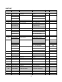
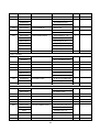
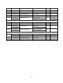
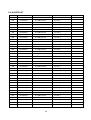
PART LIST
REF No.
PART CODE
PART NAME
DESCRIPTION
Q'TY
REMARK
ASS'Y PLATE
P01
3614511900
PLATE T
HIPS
1
P02
3612723300
HARNESS AS
AC 220V/50Hz, 60Hz
1
3612723310
AC 110V/50Hz, 60Hz
3612723340
AC 100V/50, 60Hz
P03
3614213100
PANEL F
HIPS
1
P04
3611609200
DECORATOR
PC FILM 0.254t
1
P05
PRPSSWUU00
PCB ASS'Y
DWF-4220 (PUMP)
1
PRPSSWUV00
DWF-4220 (JE)
PRPSSWUW00
DWF-4220 (NON-PUMP)
P06
3611524800
CUSHION (to PANEL F)
CR
1
P07
36100B4040
ASS'Y PUMP BUBBLE
AC 220V/60Hz
1
36100B4050
AC 100-130V/60Hz
36100B4030
AC 220-240V/50Hz
P08
3614800100
SENSOR PRESSURE
DCSV PS-D6
1
P09
3610402000
BODY INLET
FRPP (HOT, COLD)
1
3610402010
P10
3615402010
option
FRPP (COLD)
VALVE INLET (COLD)
AC 220V/60Hz
1
Peru, etc
3615403310
AC 110-120V/50, 60Hz
Japan
3615403510
AC 110-130/60Hz
Taiwan
3615403710
AC 220-240V/50Hz
Chile
3615402130
VALVE INLET (HOT)
AC 220V/60Hz
1
Peru, etc
3615403630
AC 110-130V/60Hz
Taiwan
3615403830
AC 220-240V/50Hz
Chile
P11
3619006350
SWITCH SAFETY
DC 15V 10mA
1
P12
5EPU061750
TRANS POWER
AC 230V/50Hz T2-V2
1
5EPU061770
AC 110V/50Hz T2-V1
P13
3611712500
DOOR F
HIPS
1
P14
3612602100
HANDLE DOOR
HIPS
1
P15
3611712400
DOOR B
HIPS
1
p16
3611523300
CUSHION DOOR
NBR
4
P17
3612901900
HINGE DOOR
POM
2
P18
3615106700
SPRING
SUS 304 D=1.6
1
P19
3614213200
PANEL B
HIPS
1
P20
3619008800
SWITCH POWER
125V/10A, 250V/5A 2P
1
P21
3610905500
CAP PANEL B
HIPS
1
P22
3612300100
GASKET (to VALVE INLET)
SILICON
2
P23
4505E08050
CAP (to VALVE INLET)
PVC
2
42
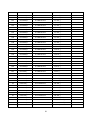
REF No.
PART CODE
PART NAME
DESCRIPTION
3616102800
BALANCER AS
PP
Q'TY
REMARK
1
DWF-4220
ASS'Y TUB
T01
3616003100
T02
3618803500
PP
TUB I
PP
3618805400
DWF-5020
1
YUS 430D 0.6t
DWF-4220
DWF-5020
T32
3618805300
TUB U
PP
1
DWF-5020
T03
3612502500
GUIDE FILTER
PP
1
DWF-4220
3612506310
PP
DWF-5020
T04
4505E05021
FLANGE TUB
ADC-10
1
T05
3610085500
ASS'Y FILTER
PP (NYLON 74x130)
1
T06
3618804000
TUB O
PP (PUMP, BUBBLE)
1
3618804100
PP (PUMP, NON-BUBBLE)
3618803400
PP (NON-PUMP, BUBBLE)
3618804200
PP (NON-PUMP, NON-BUBBLE)
T07
4500D83100
NOZZLE AS
BUBBLING AS
1
T08
4500D08170
HOSE (to BUBBLE)
ID=8.0, OD=12
0.4
T09
4500D08180
CLAMP
SWC
1
T10
4509L83070
SPECIAL WASHER
SUS 304 T2.0 P144
1
T11
4507D83080
SPECIAL NUT
SUS 340
1
T12
3619702200
PULSATOR AS
PP
1
T13
4505E32030
SC. PULSATOR FIX AS
6x2.5 SCREW + RING O
1
T14
3611408300
COVER TUB
PP
1
T15
3610302900
BASE
SECEN 1.6t
1
T16
4505E83120
SCREW BASE FIX
SM 5x13
4
T17
4505E83100
SPECIAL BOLT BASE
6.5x23
10
T18
3964311030
MOTOR CONDENSER
220V/50Hz (PN, NE)
1
T19
3964220710
110V/60Hz (PT, TE)
3964130110
100V/50, 60Hz (JE)
3964310430
240V/50Hz (PM, ME)
3964320710
220V/60Hz (PL, LE)
3964820710
120, 127V/60Hz (PA, PS, SE)
3618401420
ASS'Y PULLEY MOTOR
ADC-12 DP=53 (50Hz)
3618402800
ADC-12 DP=48.5 (60Hz)
T20
4505E34030
SPECIAL WASHER
NYLON 6/6
2
T21
7650802511
BOLT HEX (to MOTOR)
6B-1, 8x25, HS, MFZN
2
T22
3617303800
GEAR MECHANISM
GM-4200 NTN
1
T23
7640801611
BOLT HEX (to GEAR)
6B-1, 8x16, SW, MFZN
4
T24
4507B34020
BELT V
M19.5
1
T25
3618301300
PROTECTOR GEAR
SBHG 1.6t
1
43
REF No.
PART CODE
PART NAME
DESCRIPTION
T26
7640061611
BOLT HEX (to PROTECTOR)
6B-1, 6x16, SW, MFZN
2
T27
3966130120
MOTOR SYNCHRONOUS
100V/50, 60Hz (JE)
1
450ED45020
110-130V/60Hz (PT/S/A)
3966010140
220-240V/50Hz (PN/M)
Q'TY
T28
3615404000
VALVE DRAIN AS
NON-PUMP
1
T29
3613215100
HOSE DRAIN I AS
PUMP
1
3613210300
T30
T31
3610032640
NON-PUMP
UNIT CAPACITOR AS
13.5µF+60µH (PL, LE)
3618909300
65µF+60µH (JE)
3610076140
54µF+60µH (PT, TE)
3610031940
12.5µF+60µH (PN, NE)
3610045640
11.4µF+60µF (PM, ME)
3610076240
41.6µF+60µF (PS, SE, PA)
3613004100
1
HOLDER CONDENSER
PP
1
CABINET
SGCC 0.6t (PUMP)
1
ASS'Y CABINET
C01
3610804710
361806100
SGCC 0.6t (NON-PUMP)
C02
3614509900
PLATE UPPER
PP
1
C03
3612201800
FRAME TOP
PP
1
C04
3612601100
HANDLE CABINET
PP
1
C05
3611301100
CORD POWER AS
3x1.0 300x2 300-RTM (PN)
1
C06
WAK42H762-
A VCTFK 2x0.75 2.3m GY (PT)
WRJ42H261-
R VCTFK 2x0.75 2.3m GY (JE)
4505D81010
BUSHING CORD
SR 6P-4 or DA-6NR2 (PN)
3610701700
C07
1
DA-6NF2 (JE)
3610068700
HARNESS OUTER
50/0.18 GREEN, ST710489-2
1
3610307100
BASE U
PP (PUMP)
1
ASS'Y BASE
B01
3610304200
PP (NON-PUMP)
B02
3612000200
FIXTURE LEG
PPG
1
B03
3617701500
LEG AS
PP
1
B04
3613004300
HOLDER LEG
BUTYL RUBBER
1
B05
4509D10020
FOOT
BUTYL RUBBER
3
B06
3963513430
MOTOR SHADED POLE
220-240V/50Hz (PN, PM)
1
3963220330
110V/60HZ (PT)
36189
120V/60Hz (PA, PS)
3963322730
220V/60Hz (PL)
B07
3611405301
COVER PUMP
UL/CSA (466FWU)
1
B08
3611109700
CASE FILTER
FRPP
1
44
REMARK
REF No.
PART CODE
PART NAME
DESCRIPTION
B09
3611901800
FILTER LINT
P.P (5-150)
1
B10
3614002000
PACKING
NBR
1
B11
3616004300
SPECIAL WASHER
P.C SHEET
1
B12
3610903800
CAP FILTER
P.P (J-150)
1
B13
3618703770
TERMINAL PUMP
CONNECTOR
1
3618703720
Q'TY
CONNECTOR+FUSE
REMARK
PN/PL
PT
ASS'Y WASHING MACHINE
W01
3619801600
SUSPENSION AS
DWF-4200 SERIES (Front)
2
W02
3619801610
SUSPENSION AS
DWF-4200 SERIES (Back)
2
W03
3611411800
COVER BACK
PP (PUMP)
1
3611404400
W04
3618903300
PP (NON-PUMP)
UNIT FUSE FILTER
250V 4A (PN, NE)
3618903360
1
125V 8A (PT, TE, JE)
ASS'Y ACCESSORY
A01
3613203101
HOSE AS
PUMP
1
3613209200
HOSE DRAIN O AS
NON-PUMP
1
A02
3612502300
GUIDE DRAIN HOSE
PP (PUMP)
1
A03
3611411900
COVER U
PP
1
45
For UL/CSA
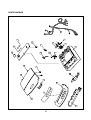
PARTS DIAGRAM
P02
P10
P23
P20
P10
P09
P12
P22
P01
P18
P08
P11
P18
P16
P07
P15
P14
P03
P04
P13
P05
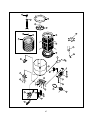
46
T05
T14
T03
T13
T12
*DWF-4220
T04
T11
T01
T10
T02
T02
T07
T32
T08
T30
T27
T06
T31
T22
T18
T15
T23
T20
T21
T16
T17
*NON-PUMP MODEL
T28
T24
T19
T29
T25
T17
T26
T29
47
W01
C02
W01
C03
C04
C01
W03
B14
B13
NON-PUMP
MODEL
A01
B08
C05
W04
B01
A02
A01
B12
B11
B10
B09
B08
B05
B13
B02
B07
B04
B03
B06
48
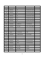
P.C.B PARTS LIST
REF No.
PART CODE
PART NAME
DESCRIPTION
R18
RD-4Z392JK
R CARBON FILM
1/4 3.9kΩ J
R26
RD-4Z392JK
R CARBON FILM
1/4 3.9kΩ J
R50
RD-4Z392JK
R CARBON FILM
1/4 3.9kΩ J
R52
RD-4Z392JK
R CARBON FILM
1/4 3.9kΩ J
R54
RD-4Z392JK
R CARBON FILM
1/4 3.9kΩ J
R55
RD-4Z392JK
R CARBON FILM
1/4 3.9kΩ J
R63
RD-4Z392JK
R CARBON FILM
1/4 3.9kΩ J
R67
RD-4Z392JK
R CARBON FILM
1/4 3.9kΩ J
R69
RD-4Z392JK
R CARBON FILM
1/4 3.9kΩ J
R70
RD-4Z392JK
R CARBON FILM
1/4 3.9kΩ J
R71
RD-4Z392JK
R CARBON FILM
1/4 3.9kΩ J
R72
RD-4Z392JK
R CARBON FILM
1/4 3.9kΩ J
R73
RD-4Z392JK
R CARBON FILM
1/4 3.9kΩ J
R74
RD-4Z392JK
R CARBON FILM
1/4 3.9kΩ J
R75
RD-4Z392JK
R CARBON FILM
1/4 3.9kΩ J
R9
RD-4Z221JK
R CARBON FILM
1/4 220Ω J
R24
RD-4Z221JK
R CARBON FILM
1/4 220Ω J
R25
RD-4Z221JK
R CARBON FILM
1/4 220Ω J
R30
RD-4Z221JK
R CARBON FILM
1/4 220Ω J
R31
RD-4Z221JK
R CARBON FILM
1/4 220Ω J
R32
RD-4Z221JK
R CARBON FILM
1/4 220Ω J
R33
RD-4Z221JK
R CARBON FILM
1/4 220Ω J
R34
RD-4Z221JK
R CARBON FILM
1/4 220Ω J
R35
RD-4Z221JK
R CARBON FILM
1/4 220Ω J
R36
RD-4Z221JK
R CARBON FILM
1/4 220Ω J
R37
RD-4Z221JK
R CARBON FILM
1/4 220Ω J
R43
RD-4Z221JK
R CARBON FILM
1/4 220Ω J
R44
RD-4Z221JK
R CARBON FILM
1/4 220Ω J
R45
RD-4Z221JK
R CARBON FILM
1/4 220Ω J
R46
RD-4Z221JK
R CARBON FILM
1/4 220Ω J
R47
RD-4Z221JK
R CARBON FILM
1/4 220Ω J
R48
RD-4Z221JK
R CARBON FILM
1/4 220Ω J
R57
RD-4Z221JK
R CARBON FILM
1/4 220Ω J
R58
RD-4Z221JK
R CARBON FILM
1/4 220Ω J
R64
RD-4Z221JK
R CARBON FILM
1/4 220Ω J
R66
RD-4Z221JK
R CARBON FILM
1/4 220Ω J
R13
RD-4Z331JK
R CARBON FILM
1/4 330Ω J
49
REMARK
REF No.
PART CODE
PART NAME
DESCRIPTION
R19
RD-4Z331JK
R CARBON FILM
1/4 330Ω J
R61
RD-4Z223JK
R CARBON FILM
1/4 22kΩ J
R14
RD-4Z103JK
R CARBON FILM
1/4 10kΩ J
R15
RD-4Z103JK
R CARBON FILM
1/4 10kΩ J
R16
RD-4Z103JK
R CARBON FILM
1/4 10kΩ J
R17
RD-4Z103JK
R CARBON FILM
1/4 10kΩ J
R22
RD-4Z103JK
R CARBON FILM
1/4 10kΩ J
R23
RD-4Z103JK
R CARBON FILM
1/4 10kΩ J
R27
RD-4Z103JK
R CARBON FILM
1/4 10kΩ J
R28
RD-4Z103JK
R CARBON FILM
1/4 10kΩ J
R29
RD-4Z103JK
R CARBON FILM
1/4 10kΩ J
R38
RD-4Z103JK
R CARBON FILM
1/4 10kΩ J
R39
RD-4Z103JK
R CARBON FILM
1/4 10kΩ J
R40
RD-4Z103JK
R CARBON FILM
1/4 10kΩ J
R41
RD-4Z103JK
R CARBON FILM
1/4 10kΩ J
R42
RD-4Z103JK
R CARBON FILM
1/4 10kΩ J
R49
RD-4Z103JK
R CARBON FILM
1/4 10kΩ J
R51
RD-4Z103JK
R CARBON FILM
1/4 10kΩ J
R53
RD-4Z103JK
R CARBON FILM
1/4 10kΩ J
R56
RD-4Z103JK
R CARBON FILM
1/4 10kΩ J
R60
RD-4Z103JK
R CARBON FILM
1/4 10kΩ J
R62
RD-4Z103JK
R CARBON FILM
1/4 10kΩ J
R10
RD-2Y620J-
R CARBON FILM
1/2 62Ω J
R11
RD-2Y620J-
R CARBON FILM
1/2 62Ω J
R12
RD-2Y620J-
R CARBON FILM
1/2 62Ω J
R20
RD-2Y620J-
R CARBON FILM
1/2 62Ω J
R21
RD-2Y620J-
R CARBON FILM
1/4 62Ω J
R1
RS01Y101J-
R M-OXIDE FILM
1W 100Ω J
R2
RS01Y101J-
R M-OXIDE FILM
1W 100Ω J
R3
RS01Y101J-
R M-OXIDE FILM
1W 100Ω J
R4
RS01Y101J-
R M-OXIDE FILM
1W 100Ω J
R5
RS01Y101J-
R M-OXIDE FILM
1W 100Ω J
R6
RS01Y101J-
R M-OXIDE FILM
1W 100Ω J
R7
RS01Y101J-
R M-OXIDE FILM
1W 100Ω J
R8
RS01Y101J-
R M-OXIDE FILM
1W 100Ω J
RA1
RA-85X103J
R ARRAY
5P (4) 1/8 10kΩ J
RA2
RA-85X103J
R ARRAY
5P (4) 1/8 10kΩ J
C21
CCZF1E103Z
C CERA
25V 0.01µF Z AXL 2
50
REMARK
REF No.
PART CODE
PART NAME
DESCRIPTION
C24
CCZF1E103Z
C CERA
25V 0.01µF Z AXL 2
C2
CCKF1H104Z
C CERA
HIKF 50V 0.1µF Z AXL 2
C4
CCKF1H104Z
C CERA
HIKF 50V 0.1µF Z AXL 2
C6
CCKF1H104Z
C CERA
HIKF 50V 0.1µF Z AXL 2
C8
CCKF1H104Z
C CERA
HIKF 50V 0.1µF Z AXL 2
C10
CCKF1H104Z
C CERA
HIKF 50V 0.1µF Z AXL 2
C12
CCKF1H104Z
C CERA
HIKF 50V 0.1µF Z AXL 2
C14
CCKF1H104Z
C CERA
HIKF 50V 0.1µF Z AXL 2
C19
CCKF1H104Z
C CERA
HIKF 50V 0.1µF Z AXL 2
C27
CCKF1H104Z
C CERA
HIKF 50V 0.1µF Z AXL 2
C29
CCKF1H104Z
C CERA
HIKF 50V 0.1µF Z AXL 2
C17
CXCH1H330J
C CERA
50V CH 33pF J (TAPPING)
C18
CXCH1H330J
C CERA
50V CH 33pF J (TAPPING)
C20
CEXE1C470A
C ELECTRO
16V RS 47µF 6.3x11
C22
CEYE1C102A
C ELECTRO
16V RS 1000µF 13x20
C25
CEXE1C471A
C ELECTRO
16V RS 470µF 10x20
C26
CEXF1V102A
C ELECTRO
35V RSS 1000µF 13x25
C1
CMXB2E683J
C MYLAR
EU 250V 0.068µF J
C3
CMXB2E683J
C MYLAR
EU 250V 0.068µF J
C5
CMXB2X103J
C MYLAR
EU 600V 0.01µF J
C7
CMXB2X103J
C MYLAR
EU 600V 0.01µF J
C9
CMXB2X103J
C MYLAR
EU 600V 0.01µF J
C11
CMXB2X223J
C MYLAR
AC 250V 0.022µF J
C13
CMXB2X223J
C MYLAR
AC 250V 0.022µF J
D1
DKN4003A--
DIODE
KN4003A AUTO 26mm
D2
DKN4003A--
DIODE
KN4003A AUTO 26mm
D3
DKN4003A--
DIODE
KN4003A AUTO 26mm
D4
DKN4003A--
DIODE
KN4003A AUTO 26mm
D5
DKN4003A--
DIODE
KN4003A AUTO 26mm
D6
DKN4148---
DIODE
KN4148 AUTO 26mm
D7
DKN4148---
DIODE
KN4148 AUTO 26mm
D8
DKN4148---
DIODE
KN4148 AUTO 26mm
D9
DKN4148---
DIODE
KN4148 AUTO 26mm
D10
DKN4148---
DIODE
KN4148 AUTO 26mm
D11
DKN4148---
DIODE
KN4148 AUTO 26mm
D12
D1N5399---
DIODE
1N5399
Q15
TZTA1271Y-
TR
KTA1271Y (AUTO)
Q1
TZTA1270Y-
TR
KTA1270Y (AUTO ) (562Y)
51
REMARK
REF No.
PART CODE
PART NAME
DESCRIPTION
Q3
TZTA1270Y-
TR
KTA1270Y (AUTO ) (562Y)
Q4
TZTA1270Y-
TR
KTA1270Y (AUTO ) (562Y)
Q5
TZTA1270Y-
TR
KTA1270Y (AUTO ) (562Y)
Q7
TZTA1270Y-
TR
KTA1270Y (AUTO ) (562Y)
Q8
TZTA1270Y-
TR
KTA1270Y (AUTO ) (562Y)
Q9
TZTA1270Y-
TR
KTA1270Y (AUTO ) (562Y)
Q10
TZTA1270Y-
TR
KTA1270Y (AUTO ) (562Y)
Q11
TZTA1270Y-
TR
KTA1270Y (AUTO ) (562Y)
Q12
TZTA1270Y-
TR
KTA1270Y (AUTO ) (562Y)
Q13
TZTA1270Y-
TR
KTA1270Y (AUTO ) (562Y)
Q14
TZTA1270Y-
TR
KTA1270Y (AUTO ) (562Y)
Q2
TZTC3202Y-
TR
KTC3202Y (AUTO) (1959Y)
Q6
TZTC3202Y-
TR
KTC3202Y (AUTO) (1959Y)
CN1
3612723600
HARNESS AS
LP-09 (DWF-4220)
CN2
3612723500
HARNESS AS
LP-06 (DWF-4220)
HS1
4509D72050
HEAT SINK
REGULATER, 25x35x20
HS2
3617400300
HEAT SINK
50x50 T=3 (DWF-6688AT)
BUZZ1
4507B72160
BUZZER
WFB20-16PC
IC1
13GR47C840
IC MICOM
TMP47C840N
IC2
1S8054HNZ-
IC AUDIO RESET
S-8054HN
IC3
TPC817C
PHOTO COUPLER
PC817C
IC4
1L7806----
IC REGULATOR
L7806
NUT
7391300311
NUT HEX
6N-1-3 MFZN
SCREW
7001301011
SCREW MACHINE
PAN 3X10 MFZN
TRC1
TSM12JZ47F
TRIAC TOSHIBA
12A, LEAD FORMING TYPE
TRC2
TSM12JZ47F
TRIAC TOSHIBA
12A, LEAD FORMING TYPE
TRC3
TBCR1AMAB
TRIAC
BCR1AM FORMING TYPE
TRC4
TBCR1AMAB-
TRIAC
BCR1AM FORMING TYPE
TRC5
TSM8JZ47F
TRIAC
8A INSULATION TYPE
TRC6
TSM3JZ47F
TRIAC
3A INSULATION TYPE
TRC7
TSM3JZ47F
TRIAC
3A INSULATION TYPE
WAS
4507D72300
SPECIAL WASHER
REGULATOR TRIAC
X-TAL
5P4R194304
CRISTAL OSCILATOR
4.194304 MHz
LED1
DDLR523D--
LED-LAMP
DLR523D
LED2
DDLR523D--
LED-LAMP
DLR523D
LED3
DDLR523D--
LED-LAMP
DLR523D
LED4
DDLR523D--
LED-LAMP
DLR523D
LED5
DDLR523D--
LED-LAMP
DLR523D
52
REMARK
REF No.
PART CODE
PART NAME
DESCRIPTION
LED6
DDLR523D--
LED-LAMP
DLR523D
LED7
DDLR523D--
LED-LAMP
DLR523D
LED8
DDLR523D--
LED-LAMP
DLR523D
LED9
DDLR523D--
LED-LAMP
DLR523D
LED10
DDLR523D--
LED-LAMP
DLR523D
LED11
DDLR523D--
LED-LAMP
DLR523D
LED12
DDLR523D--
LED-LAMP
DLR523D
LED13
DDLR523D--
LED-LAMP
DLR523D
LED14
DDLR523D--
LED-LAMP
DLR523D
SW1
5S50101400
SW TACT
KQB-902 1C 1P
SW2
5S50101400
SW TACT
KQB-902 1C 1P
SW3
5S50101400
SW TACT
KQB-902 1C 1P
SW4
5S50101400
SW TACT
KQB-902 1C 1P
SW5
5S50101400
SW TACT
KQB-902 1C 1P
HOLDER1
3613006300
HOLDER LED
DWF-4220
HOLDER2
3613006300
HOLDER LED
DWF-4220
HOLDER3
3613006300
HOLDER LED
DWF-4220
HOLDER4
3613006300
HOLDER LED
DWF-4220
53
REMARK
CIRCUIT DIAGRAM [PUMP]
BL/YW
RA1
Q8
A1270
10K
R67
100 1W
R53 10
3.9K
30 TEST
+6V
R52 9
R5.3
10K
10K
R71
R13
330 R1/4W
3.9K
18 P11
C7
R4
3.9K
IC2
TOSHIBA R42 5
TMP47C840N
STANDARD
R9 220
R19
62 R1/2W
R43 6
WARM
WED
R11
62 R1/2W
Q15
A1271
10K
R75
COLD
LOW
1K
RA2
MIN
R57 220
DRY/WOOL
BUZZER
R15 10K
R23 220
25 P23
WASH
R81 T2 35
R34 220
19 P12
C16
104Z
R70 13
BL/WH
BL/WH
A8
DRAIN
PUMP
A8
HOT V/V
YW
A3
A3
A1
A1
YW
WH/RD
COLD V/V
RD/BL
RD/BL
FUSE
Q11
1N4148
R14 10K
Q2
C3202
R24 220
RINCE
1 1
TBIAC7
R16 10K
Q1
A1270
R80 1NT2 36
PK
233K
250VAC
R13 20
R58 220
A2
2 2
SM3JZ47
C14
104Z
+6V
24 P22
DHY
C13
100 1W
R64 220
A2
TRIAC6
R7
R40 3
DIRTY
PK
SM3JZ47
C12
114Z
R9 220
23 P21
DRAIN
MOTOR
YW/BK
233K
250VAC
C11
100 1W
3.9K
A4
BUBBLE PUMP
SM8JZ47
10K
R41 4
SPEED
A4
TRIAC5
R3
Q14
A1270
10K
R74
YW/BK
103K
250VAC
C6
104Z
R11
62 R1/2W
22 P20
C5
100 1W
3.9K
250VAC
TRIAC4
R3
Q13
A1270
10K
R73
BL
W/M LEFT
BCR1AM
C8
104Z
3
HI
11 R60
A6
103K
4
R66 220
Q07
A1270
HOT
R72
A6
250VAC
Q12
A1270
10K
MOTOR
TRIAC3
100 1W
R62
10K
103K
W/M RIGHT
WH/RD
R2W
100K
BCR1AM
C10
104Z
R50 7
R55 3.9K
C9
VT
RUNNING CAPACITOR
BL
RB
TRIAC 2
100 1W
Q10
A1270
10K
R70
A5
SAFTY S/W
1
Q5
A1270
R56
10K
R12
330 R1/4W
3.9K
17 P10
SM12JZ247
R5
R51 8
R54 3.9K
Q4
A1270
250VAC
C4
104Z
Q11
A1270
A5
D12
1N5399
683K
C3
100 1W
R20
62 R1/2W
3.9K
34 HOLD
VT
TRIAC1
R2
Q9
A1270
10K
R69
SM12JZ47
C2
104Z
R21
62 R1/2W
A7
2
21 VSS
BL/YW
A7
C1 683K 250VAC
R1
GN/WH
IC3 PC817
R18
3.9K
R17
10K
A9
A9
GN/WH
1 1
2 2
R48 220
R83 T1 38
C17 33pF
MENU
D10
LEVEL
STOP/ START
D6
D7
R36 220
39 R90
COURSE
D9
XIN 31
VDD 42
R35 220
40 R91
R23 10K
33pF
R37 220
1
+
_ C20
47µF
10V
IC2
RESET I.C
5-8054HN
P47 220
3
+
+
C22 _
470µF
16V
R50
3.9K
C25
470µF
16V
R41 10K
_
IC4
REGULATOR
7806
C28
C27
104Z
104Z
D3 1N4003
+
R28 10K
27 K01
R71 14
J7 (FEED RNS)
R27 10K
R30 220
R42 10K
R72 15
26 K00
B1
B3
B3
B6
B6
B5
B5
B4
B4
1 1
BK/WH
2 2
WH
3 3
PRESSURE
SENSOR
_
C26
1000µF
35V
OR
C24
103Z
OR
D4 1N4003
RD
1 1
RD
2 2
GY
TRANS
R60 10K
R61 22K
VARISTER
FUSE
J8 (RSV/NOS)
R29 10K
R32 220
R46 220
B1
POWER S/W
BR
D2 1N4003
GY
Q6
C3202
R31 220
R45 220
B2
D1 1N4003
C21
103Z
28 K02
J16
D5 1N4003
R82(INT1) 37
R44 220
J17
WH
B2
6V
29 K03
R40 10K
BK/WH
R49 10K
R38 10K
R43 220
J18
R52 3.9K
Q3
A1270
5.4V
C29
104Z
C19
104Z
R39 10K
J19
BR
R51
10K
RESET 33
5.4V
R26 3.9K
XTAL
4.1943MHz
C18
R22 10K
D8
R33 220
XOUT 32
2
NOS
J9 (DRY/WOOL)
R73 16
LI NE COIL
54
CIRCUIT DIAGRAM [NON-PUMP]
BL/YW
RA1
21 VSS
Q8
A1270
10K
R67
100 1W
R53 10
3.9K
30 TEST
+6V
R52 9
R5.3
10K
10K
R71
Q5
A1270
R56
10K
R12
330 R1/4W
3.9K
17 P10
R13
330 R1/4W
3.9K
18 P11
C9
C7
R4
HOT
HI
11 R60
R9 220
WED
A6
A6
BL
W/M LEFT
250VAC
YW/BK
A4
A4
DRAIN
MOTOR
YW/BK
BUBBLE PUMP
BCR1AM
PK
A2
A2
PK
1 1
TRIAC4
2 2
10K
3.9K
BL/WH
R73
DRAIN
PUMP
A8
3.9K
10K
R74
10K
Q14
A1270
WH/RD
HOT V/V
R11
62 R1/2W
R41 4
SPEED
WH/RD
103K
C8
104Z
22 P20
WARM
MOTOR
R43 6
IC2
TOSHIBA R42 5
TMP47C840N
STANDARD
W/M RIGHT
250VAC
R72
R66 220
Q07
A1270
103K
VT
TRIAC3
100 1W
R62
10K
A5
RUNNING CAPACITOR
R2W
100K
BCR1AM
C10
104Z
R50 7
R55 3.9K
A5
BL
RB
TRIAC 2
100 1W
Q10
A1270
10K
R70
SM12JZ247
R5
R51 8
R54 3.9K
Q4
A1270
250VAC
C4
104Z
Q11
A1270
A7
D12
1N5399
683K
C3
100 1W
R20
62 R1/2W
3.9K
34 HOLD
VT
TRIAC1
R2
Q9
A1270
10K
R69
SM12JZ47
C2
104Z
R21
62 R1/2W
BL/YW
A7
C1 683K 250VAC
R1
3.9K
A3
YW
R9 220
23 P21
10K
R75
1K
RA2
R57 220
DRY/WOOL
BUZZER
R15 10K
25 P23
R81 T2 35
R34 220
19 P12
C16
104Z
R70 13
R14 10K
Q2
C3202
R24 220
WASH
A1
FUSE
315mA/250V AC
Q11
1N4148
R16 10K
Q1
A1270
RD/BL
A1
SAFTY S/W
1
R23 220
R80 1NT2 36
COLD V/V
RD/BL
TBIAC7
R13 20
R58 220
RINCE
223K
250VAC
SM3JZ47
C14
104Z
+6V
24 P22
MIN
C13
100 1W
R64 220
DHY
R7
R40 3
DIRTY
4
LOW
3
COLD
2
Q15
A1271
GN/WH
IC3 PC817
R18
3.9K
R17
10K
A9
A9
GN/WH
1 1
2 2
R48 220
R83 T1 38
C17 33pF
MENU
D10
LEVEL
STOP/ START
D6
D7
R36 220
39 R90
COURSE
D9
XIN 31
VDD 42
R35 220
40 R91
R23 10K
33pF
R37 220
1
+
_ C20
47µF
10V
IC2
RESET I.C
5-8054HN
P47 220
3
+
+
C22 _
470µF
16V
R50
3.9K
C25
470µF
16V
R41 10K
_
IC4
REGULATOR
7806
C28
C27
104Z
104Z
D3 1N4003
+
R28 10K
27 K01
R71 14
J7 (FEED RNS)
R27 10K
R30 220
R42 10K
R72 15
26 K00
B1
B3
B3
B6
B6
B5
B5
B4
B4
1 1
BK/WH
2 2
WH
3 3
PRESSURE
SENSOR
_
C26
1000µF
35V
OR
C24
103Z
OR
D4 1N4003
RD
1 1
RD
2 2
GY
TRANS
R60 10K
R61 22K
VARISTER
FUSE
AC125V/8A
J8 (RSV/NOS)
R29 10K
R32 220
R46 220
B1
POWER S/W
BR
D2 1N4003
GY
Q6
C3202
R31 220
R45 220
B2
D1 1N4003
C21
103Z
28 K02
J16
D5 1N4003
R82(INT1) 37
R44 220
J17
WH
B2
6V
29 K03
R40 10K
BK/WH
R49 10K
R38 10K
R43 220
J18
R52 3.9K
Q3
A1270
5.4V
C29
104Z
C19
104Z
R39 10K
J19
BR
R51
10K
RESET 33
5.4V
R26 3.9K
XTAL
4.1943MHz
C18
R22 10K
D8
R33 220
XOUT 32
2
NOS
J9 (DRY/WOOL)
R73 16
LI NE COIL
55
BARE PCB
TOP
BOTTOM
56