1
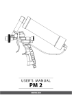
WALL OVEN
TECHNICAL SERVICE GUIDE
Models:
■
■
■
■
■
■
WO-227SS
WO-227PL
WO-227GN
WO-227BL
WO-227WT
WO-227BK
■
■
■
■
■
■
WO-127SS
WO-127PL
WO-127GN
WO-127BL
WO-127WT
WO-127BK
■
■
■
■
■
■
WO-230SS
WO-230PL
WO-230GN
WO-230BL
WO-230WT
WO-230BK
■
■
■
■
■
■
WO-130SS
WO-130PL
WO-130GN
WO-130BL
WO-130WT
WO-130BK
To Our Valued Service Partners
DCS is a leading manufacturer of premium quality cooking and speciality appliances for both
residential and professional use. We are proud of our reputation for quality and our commitment to
customer satisfaction. We have set high standards for ourselves along with our network of
independent Part Distributors and Service Agencies.
As an Authorized Part Distributor or Authorized Service Agency we are counting on you to represent
our company in a professional manner. We are here to help support you should you need help.
Our technical support center is staffed by experienced technicians eager to help you. Our number is
(888) 396-2665 and we are available 6:00 am (pst) to 4:30 pm (pst).
In addition, should we be needed, our team of customer service representatives are available to help
you resolve any customer inquiry. The telephone number (888) 281-5698 (6 am - 4:30 pm pst)
Remember, we are here to support you and our customers. This service manual is designed to provide
you with the information needed to properly diagnose and repair the Wall Oven. We are proud of this
appliance as we believe it offers a terrific cooking experience. Your understanding of the design and
function of this appliance is an important part of the repair process.
If you need help please contact us.
Sincerely,
DCS, Customer Service Team
1
Table Of Contents
SAFETY PRACTICES & PRECAUTIONS...............................................................................3
SPECIFICATIONS ..............................................................................................................................4-7
PRODUCT IDENTIFICATION ......................................................................................................8
PARTS IDENTIFICATION
ECO Failure Codes.........................................................................................................................9
Oven Can Assembly .....................................................................................................................10
Oven Can Parts List .....................................................................................................................11
Oven Door Assembly...................................................................................................................12
Oven Door Parts List ............................................................................................................13-15
Display Assembly ...........................................................................................................................16
Display Parts List...........................................................................................................................17
Upper Oven Assembly .................................................................................................................18
Upper Oven Parts List.................................................................................................................19
Lower Oven Assembly.................................................................................................................20
Lower Oven Parts List.................................................................................................................21
Bake Parts List / Assembly ..........................................................................................................22
Hardware Parts List................................................................................................................23-24
OPERATING INSTRUCTIONS .............................................................................................25-32
Oven Display / Setting Clock .....................................................................................................25
Setting Bake Mode ..................................................................................................................25-26
Convection Bake .....................................................................................................................26-27
Convection Roast....................................................................................................................27-28
Setting Broil ....................................................................................................................................28
Setting Timers ................................................................................................................................29
Using Food Probe ...................................................................................................................29-30
Timed Cooking........................................................................................................................30-31
Oven Calibration...........................................................................................................................32
Temperature Settings ...................................................................................................................32
COMPONENT ACCESS.............................................................................................................33-36
Element Removal / Convection Motor....................................................................................33
Rear Components.........................................................................................................................34
Blower Motor / Thermostat.......................................................................................................35
High Temperature Cut-out..........................................................................................................36
OVEN CONTROL REMOVAL ................................................................................................37-38
LATCH REMOVAL ...............................................................................................................................39
ELEMENT REPLACEMENT...........................................................................................................40
CURRENT FLOW & OPERATION .....................................................................................41-43
Elements ..........................................................................................................................................41
Upper Oven .............................................................................................................................41-42
Lower Oven .............................................................................................................................42-43
WARRANTY ............................................................................................................................................44
2
Safety Practices & Precautions
Please read all sections of this manual and retain for future reference.
WARNING: If these important safety precautions are not followed exactly, a fire or explosion
may result, causing property damage, personal injury, or death.
• Never store or use gasoline or other flammable vapors and liquids in the vicinity of this or any other
appliance.
NOTE: Installation and service must be performed by a qualified installer, and service agency.
Electrical requirements: 240V 35amp (27 & 30 single oven) and 50amp for (227 &
230 double oven). Hard wire should be use.
When properly cared for, your new DCS appliance has been designed to be safe,and reliable.When
using this restaurant caliber appliance, use it with extreme care, as this type appliance provides intense
heat and can increase the accident potential. Basic safety precautions must be followed when using
kitchen appliances, including the following:
Read this Service & Parts Manual thoroughly before servicing appliance.This will help to reduce the risk
of fire, electric shock, or injury to persons. Begin by insuring proper installation and servicing. Follow
the installation instructions which came with this appliance. Be sure to have a qualified technician install
and ground this appliance before using.
• Do not repair or replace any part of this appliance unless it is specifically recommended in this
manual. All other servicing should be referred to a qualified service technician.
WARNING: Children should not be left alone or unattended in an area where appliances are
in use.They should never be allowed to turn knobs, push buttons, sit or stand on
any part of an appliance.
CAUTION: Do not store items of interest to children on or around the Wall Oven. Children
could be seriously injured if they should climb onto or reach across the appliance
to reach these items.
• Never store anything in the Wall Oven. Flammable materials can accidentally catch fire, plastic items
may melt or ignite and other types of items could be ruined.
• Do not hang articles from any part of the appliance. Some fabrics are quite flammable and may catch
on fire.
• Do not use water on grease fires.Turn all knobs OFF, then smother fire with baking soda or use a dry
chemical or foam-type fire extinguisher.
• Be certain to use only dry pot holders: moist or damp pot holders on hot surfaces may cause burn
injury from steam.
• Do not use a towel or other bulky cloth in place of potholders.
3
Specifications / Dimensions
WO-127 27” Single Wall Oven
Front
Side
25-1/2"
26-7/8"
23-7/8"
29-15/16"
29-3/8"
Interior Dimension = 16"H x 22"W x 18-5/8"D
Bottom Trim screws
Rack Dimension = 21-3/8" W x 15"D
WALL OVEN
Cabinet Dimensions
WALL OVEN
Cut Out Dimensions
27"
min.
2x4's or
similar
runners
or solid
structure
support
Conduit
box centered
2" below bottom
of oven
2x4's or
similar supports
4
(Suggested
distance from
floor 6" min.)
Floor
25-1/2"
29-1/2 "
Specifications / Dimensions
WO-227 27” Double Wall Oven
Front
Side
25-1/2"
26-7/8"
23-7/8"
54-15/16 "
54-3/16 "
Bottom Trim screws
Interior Dimension = 16"H x 22"W x 18-5/8"D
Rack Dimension = 21-3/8"W x 15"D
WALL OVEN
Cabinet Dimensions
WALL OVEN
Cut Out Dimensions
27"
min.
25-1/2"
54-3/8 "
2x4's or
similar
runners
or solid
structure
support
Conduit
box centered
2" below bottom
of oven
2x4's or
similar supports
NOTE: Oven does not have to be vented to the outside
5
(Suggested
distance from
floor 6" min.)
Floor
Specifications / Dimensions
WO-130 30” Single Wall Oven
Front
Side
25-1/2"
29-7/8"
23-7/8"
29-15/16"
Bottom Trim screws
29-3/8"
Interior Dimension = 16"H x 25"W x 18-5/8"D
Rack Dimension = 24-3/8"W x 15"D
WALL OVEN
Cabinet Dimensions
30"
min.
2x4's or
similar
runners
or solid
structure
support
WALL OVEN
Cut Out Dimensions
Conduit
box centered
2" below bottom
of oven
2x4's or
similar supports
(Suggested
distance from
floor 6" min.)
28-1/2"
29-1/2 "
Floor
Note: Do not use an extension cord with this appliance, the unit must be hard wired directly to the electrical source.
6
Specifications / Dimensions
WO-230 30” Double Wall Oven
Front
Side
25-1/2"
29-7/8"
23-7/8"
54-15/16 "
54-3/16 "
Bottom Trim screws
Interior Dimension = 16"H x 25"W x 18-5/8"D
Rack Dimension = 24-3/8"W x 15"D
WALL OVEN
Cabinet Dimensions
WALL OVEN
Cut Out Dimensions
30"
min.
28-1/2"
54-3/8 "
2x4's or
similar
runners
or solid
structure
support
Conduit
box centered
2" below bottom
of oven
2x4's or
similar supports
7
(Suggested
distance from
floor 6" min.)
Floor
Product Identification
ELECTRONIC OVEN CONTROL
COOLING
FAN
VENTS
TOUCH PAD
FUNCTION KEYS
12:30
CATALYST
AIR DUCT
DOOR
LOCK*
CONVECTION FAN
(behind convection baffle)
OVEN LIGHT
CONCEALED
BROIL
ELEMENT
SIX RACK POSITIONS:
6
5
HIDDEN
CONVECTION
ELEMENT
4
3
SERIAL #
LOCATION
2
1
HIDDEN
BAKE
ELEMENT
(OVEN FLOOR)
FOOD
PROBE
(upper oven only)
*Door Lock only functions in the self clean mode
Double oven display shown
MODEL NUMBER / SERIAL IDENTIFICATION
A
B
C
D
E
F
WO – 1 – 27 - SS - BR - PSH
SERIAL NUMBER
A. Product Identifier
1. WO = Wall Oven
01A00000A
D. Color
1. SS= Stainless Steel
B. Oven Quantity
2. BK= Black
1. 1= Single
3. BL= Blue
2. 2= Double
4. GN= Green
A
B
C
5. WT= White
C. Oven Size
1. 27” Width
A= Manufactured Year. Adding the first
two digits gives you the last digit
of the year.
B= The Month of the year.
(example: A=January, B= February, etc…)
C= Service / Engineering Code
E. Brass Trim
2. 30” Width
F. Pro-Style Handle
8
Parts Identification
EOC FAILURE CODES
All failure modes give a visual and audible alarm. Failure modes can be canceled, but will return after
the appropriate debounce time if the error condition still exists.
—F7— ALARM
A shorted key for 32 seconds in a row will activate a “CANCEL” feature in both ovens.This applies to
all keys, including CANCEL. “-F7-” will be displayed in the time digits and the failure tone will sound
until the CANCEL key is pressed. If CANCEL is the shorted key, pushing another valid function key
will clear the error display and tone.This test will always be active. If other than Stop Time,Timer 1 or
Timer 2 is shorted at power up, the F7 alarm is given immediately.
-FC- ALARM
A breakdown in serial communications between the user interface board and the temperature control
board that is detected by the User Interface board for 4 to 5 seconds will cause an -FC- alarm to be
given.This error alarm is always active.
-F?- Temperature control board Alarms
Additional failure alarms can be generated by the temperature control board.These errors are
transmitted by way of the serial port to be displayed and audibly annunciated.These alarms will be
displayed in the appropriate red temperature display for the oven affected.The appropriate oven will
also be canceled.The possible errors are a follows.
-Fl-F2-F3-F4-F5-F8-F9-FF-F--Fr-
Alarm, Element supervisor enabled.
Over temp Alarm.
Open oven sensor.
Shorted oven sensor
Element supervisor disabled (upper oven).
Shorted meat probe alarm.
Error in door lock functions. (upper oven)
Bad A/D
Communications error detected by the power relay board. (upper oven)
A lower oven error that is equivalent to either an F5, F9 or F- error of the upper oven.
9
Parts List Oven Can Assembly
30
31
29
28
27
20
19
26
1
21
25
24
23
22
2
3
11
18
4
5
6
13
7
9
12
10
32
8
10
14 15
16
17
Parts List Oven Can
ITEM
1
2
3
4
5
*
6
7
8
9
10
*
11
*
12
*
13
14
15
*
16
17
18
19
20
21
22
23
24
25
26
27
28
29
30
*
31
*
*
32
*
DESCRIPTION
127/227 PART NO.
RACK ASSEMBLY
RACK ROLLER HORIZONTAL
NUT, ROLLER
CONVECTION BAFFLE W/A PORC.
CONVECTION ELEMENT
SCREWS (2)
CONVECTION MOTOR BLADE
BAFFLE SCREWS (4)
SCREW
SET SCREWS (2)
CONVECTION PAD COVER
SCREWS (4)
CONVECTION PAD
SCREWS
CONVECTION MOTOR COOLING BLADE
SCREWS (4)
CONVECTION MOTOR R/H
CONVECTION MOTOR BRACKET
TEMP SENSOR
SENSOR SCREWS (2)
FOOD PROBE (UPPER OVEN ONLY)
ROLLER SUPPORT R/H LOWER
ROLLER SUPPORT R/H UPPER
PROBE COVER (LOWER OVEN ONLY)
CATALYST
PROBE JACK (UPPER OVEN ONLY)
RACK ROLLER,VERTICAL / SCREW ASSY.
OVEN LAMP ASSEMBLY
LIGHT BULB
LIGHT RECEPTACLE / LENS
ROLLER SUPPORT L/H LOWER W/ASSY.
ROLLER SUPPORT L/H UPPER W/ASSY.
OVEN CAN WELDMENT
BROIL GLASS
BROIL ELEMENT
SCREWS
BROIL GLASS RETAINER FT / BACK
BROIL GLASS RETAINER LT / RT
SCREWS
CONVECTION MOTOR ASSEMBLY
BROIL PAN (ITEM NOT SHOWN)
* ITEMS NOT SHOWN
11
96125
14197-01
15021-04
96150-PC
16256
15001-23
16130
15001-23
15001-23
15002-34
96100
15001-36
96015
15001-23
16053
15001-36
16327
96011
16169
15001-40
16268
96127-02
96127-01
96102
12063-01
16262
14197-02
16242
16236
16237
96127-04
96127-03
96104-01
16251
16250
15001-31
96090-01
96090-02
15001-31
96108
19021-1
130/230 PART NO.
96204
14197-01
96171-PC
16256-02
96392-02
16128
96127-03
96127-02
96104-01
Parts List Oven Door Assembly
4
1
3 2
5
14 13
12
6
7
16 15
8
9
10
11
19
20
20A
17
18
23
21
22
24
12
Parts List Oven Door
ITEM
1
2
3
4
5
6
7
8
9
10
11
12
*
13
14
*
*
*
*
*
*
*
*
*
*
*
15
16
*
17
18
19
20
*
21
22
23
24
*
DESCRIPTION
127/227 PART NO.
DOOR SEAL
INNER DOOR GLASS
DOOR SEAL CHANNEL
DOOR LINER W/ASSEMBLY
HINGE TOP BRACKET
DOOR INSULATION COVER
GLASS SPACER
INNER DOOR GLASS
GLASS COVER TOP & BOTTOM
GLASS COVER SIDE
DOOR HEAT SHIELD
OUTSIDE DOOR GLASS (BLACK)
OUTSIDE DOOR GLASS (WHITE)
HANDLE STIFFENER
DOORSKIN S/STEEL NO LOGO
DOORSKIN S/STEEL WITH LOGO
DOORSKIN BLACK NO LOGO
DOORSKIN BLACK WITH LOGO
DOORSKIN BLUE NO LOGO
DOORSKIN BLUE WITH LOGO
DOORSKIN GREEN NO LOGO
DOORSKIN GREEN WITH LOGO
DOORSKIN PLATINUM NO LOGO
DOORSKIN PLATINUM WITH LOGO
DOORSKIN WHITE NO LOGO
DOORSKIN WHITE WITH LOGO
HANDLE SPACER
DOOR HANDLE
DOOR HANDLE PLATED BRASS
LOGO
LOGO CLIPS
HINGE
HINGE BOTTOM PLATE
PLATE SCREWS (4)
END CAP SS PRO-STYLE
DOOR HANDLE SS PRO-STYLE
HANDLE STIFFENER
DOOR SKIN S/S NO LOGO
DOOR HANDLE PRO STYLE BRASS
* ITEMS NOT SHOWN
13
96068
14193-01
96073
96118-PC
96001
96070
96071
14193-01
96066
96067
96137
14194-01
14194-02
96012
96113-01
96113-02
96113-08-PA
96113-07-PA
96113-10-PA
96113-09-PA
96113-12-PA
96113-11-PA
96113-14-PA
96113-13-PA
96113-06-PA
96113-05-PA
12167
12122
12122-05-PL-B
17255-01
15073
150034-1
96021
15001-22
18164-PL
96139-07
96102
96159-01
90187-11-PL-B
130/230 PART NO.
96166
14192-02
96213-PC
96192
96193
14193-02
96189
96195
14194-03
14194-04
96212-01
96212-02
96212-08-PA
96212-07-PA
96212-10-PA
96212-09-PA
96212-12-PA
96212-11-PA
96212-14-PA
96212-13-PA
96212-06-PA
96212-05-PA
12239
18164-PL
96139-32
96102
90187-13-PL-B
Parts List Oven Door
ITEM
DESCRIPTION
127/227 PART NO.
DOOR SKIN ASSEMBLIES 27” WO EURO STYLE HANDLE:
*
DOOR SKIN ASSEMBLY S/S NO LOGO
*
DOOR SKIN ASSEMBLY S/S W/ LOGO
*
DOOR SKIN ASSEMBLY WHITE NO LOGO
*
DOOR SKIN ASSEMBLY WHITE W/ LOGO
*
DOOR SKIN ASSEMBLY BLACK NO LOGO
*
DOOR SKIN ASSEMBLY BLACK W/ LOGO
*
DOOR SKIN ASSEMBLY BLUE NO LOGO
*
DOOR SKIN ASSEMBLY BLUE W/ LOGO
*
DOOR SKIN ASSEMBLY GREEN NO LOGO
*
DOOR SKIN ASSEMBLY GREEN W/ LOGO
*
DOOR SKIN ASSEMBLY PL NO LOGO
*
DOOR SKIN ASSEMBLY PL W/ LOGO
96231-01
96231-02
96231-06
96231-05
96231-08
96231-07
96231-10
96231-09
96231-12
96231-11
96231-14
96231-13
DOOR SKIN ASSEMBLIES 27” WO PRO STYLE HANDLE:
*
DOOR SKIN ASSEMBLY S/S NO LOGO
*
DOOR SKIN ASSEMBLY S/S W/ LOGO
*
DOOR SKIN ASSEMBLY WHITE NO LOGO
*
DOOR SKIN ASSEMBLY WHITE W/ LOGO
*
DOOR SKIN ASSEMBLY BLACK NO LOGO
*
DOOR SKIN ASSEMBLY BLACK W/ LOGO
*
DOOR SKIN ASSEMBLY BLUE NO LOGO
*
DOOR SKIN ASSEMBLY BLUE W/ LOGO
*
DOOR SKIN ASSEMBLY GREEN NO LOGO
*
DOOR SKIN ASSEMBLY GREEN W/ LOGO
*
DOOR SKIN ASSEMBLY PL NO LOGO
*
DOOR SKIN ASSEMBLY PL W/ LOGO
96293-01
96293-02
96293-04
96293-03
96293-06
96293-05
96293-08
96293-07
96293-10
96293-09
96293-12
96293-11
DOOR SKIN ASSEMBLIES 30” WO EURO STYLE HANDLE:
*
DOOR SKIN ASSEMBLY S/S NO LOGO
*
DOOR SKIN ASSEMBLY S/S W/ LOGO
*
DOOR SKIN ASSEMBLY WHITE NO LOGO
*
DOOR SKIN ASSEMBLY WHITE W/ LOGO
*
DOOR SKIN ASSEMBLY BLACK NO LOGO
*
DOOR SKIN ASSEMBLY BLACK W/ LOGO
*
DOOR SKIN ASSEMBLY BLUE NO LOGO
*
DOOR SKIN ASSEMBLY BLUE W/ LOGO
*
DOOR SKIN ASSEMBLY GREEN NO LOGO
*
DOOR SKIN ASSEMBLY GREEN W/ LOGO
*
DOOR SKIN ASSEMBLY PL NO LOGO
*
DOOR SKIN ASSEMBLY PL W/ LOGO
14
130/230 PART NO.
96293-13
96293-14
96293-16
96293-15
96293-18
96293-17
96293-20
96293-19
96293-22
96293-21
96293-24
96293-23
Parts List Oven Door
ITEM
DESCRIPTION
127/227 PART NO.
DOOR SKIN ASSEMBLIES 30” WO PRO STYLE HANDLE:
*
DOOR SKIN ASSEMBLY S/S NO LOGO
*
DOOR SKIN ASSEMBLY S/S W/ LOGO
*
DOOR SKIN ASSEMBLY WHITE NO LOGO
*
DOOR SKIN ASSEMBLY WHITE W/ LOGO
*
DOOR SKIN ASSEMBLY BLACK NO LOGO
*
DOOR SKIN ASSEMBLY BLACK W/ LOGO
*
DOOR SKIN ASSEMBLY BLUE NO LOGO
*
DOOR SKIN ASSEMBLY BLUE W/ LOGO
*
DOOR SKIN ASSEMBLY GREEN NO LOGO
*
DOOR SKIN ASSEMBLY GREEN W/ LOGO
*
DOOR SKIN ASSEMBLY PL NO LOGO
*
DOOR SKIN ASSEMBLY PL W/ LOGO
* ITEMS NOT SHOWN
15
130/230 PART NO.
96293-25
96293-26
96293-28
96293-27
96293-30
96293-29
96293-32
96293-31
96293-34
96293-33
96293-36
96293-35
Parts List Display Assembly
1
2
4
3
18
5
8
6
7
9
10
17
12
13
14
13
16
11
15
16
Parts List Display
ITEM
1
2
3
*
*
*
*
*
4
5
*
*
*
6
7
8
9
10
11
12
13
14
15
16
17
18
*
*
DESCRIPTION
127/227 PART NO.
CONTROL COVER FRONT
CONTROL COVER REAR
CONTROL PANEL SKIN BLACK
CONTROL PANEL SKIN GREEN
CONTROL PANEL SKIN PLATINUM
CONTROL PANEL SKIN WHITE
CONTROL PANEL SKIN STAINLESS STEEL
CONTROL PANEL SKIN BLUE
CONTROL MOUNT BRACKET TOP
CONTROL MOUNT PANEL W/ASSEMBLY BLACK DOUBLE
CONTROL MOUNT PANEL W/ASSEMBLY WHITE DOUBLE
CONTROL MOUNT PANEL W/ASSEMBLY BLACK SINGLE
CONTROL MOUNT PANEL W/ASSEMBLY WHITE SINGLE
TERMINAL BLOCK
RELAY MOUNT ENDS
CONTROL PANEL MOUNT BRACKET L/H
CONTROL BOX SIDE L/H
MAIN RELAY BOARD
OUTER AIR JACKET TOP
RELAY MOUNT CENTER
RELAY SPDT
EOC DOUBLE
CONTROL BOX SIDE R/H
CONTROL PANEL MOUNT BRACKET R/H
L/O RELAY BOARD
MOV ASSEMBLY
MEMBRANE SWITCH BLACK
MEMBRANE SWITCH WHITE
* ITEMS NOT SHOWN
17
96097-PA
96201
96116-04-PA
96116-06-PA
96116-07-PA
96116-03-PA
96116-01-PA
96116-05-PA
96094
96553-01
96553-02
96553-03
96553-01
16254
96003
96091-02
96028-02
16253
96008
96002
16271
16252
96028-01
96091-01
16267
16337-08
17201-01
17201-02
130/230 PART NO.
96200-01-PA
96201
96205-04-PA
96205-06-PA
96205-07-PA
96205-03-PA
96209-01-PA
96205-05-PA
96094
16254
96003
96091-02
96028-02
16253-01
96170
96002
16271
16252
96028-01
96091-01
16267
16337-08
17201-01
17201-02
Parts List Upper Oven Assembly
1
5
6
32
2
7
4
3
12
33
9
14B
31
10
11
8
35
36
13
30
16B
28
15
26
29
27
25
18
17
15A
15B
19
16A
39
14A
20
21
38
37
22
23
24
34
18
Parts List Upper Oven
ITEM
1
2
3
4
5
6
7
8
9
10
11
12
13
14A
14B
15
15A
16A
16B
17
18
19
20
21
22
23
24
25
26
27
28
29
30
31
32
33
34
35
36
37
38
39
DESCRIPTION
127/227 PART NO.
OUTER AIR JACKET TOP
AIR DUCT
LATCH COVER TOP
CATALYST DUCT W/ASSEMBLY
BLOWER MOTOR
BLOWER THERMOSTAT
BLOWER MOTOR BRACKET
CATALYST DUCT BRACKET
LATCH RETAINER
DOOR LATCH
LATCH MOUNT
LATCH COVER BOTTOM
UPPER AIR JACKET
OUTSIDE AIR JACKET R/H
OUTSIDE AIR JACKET L/H
SIDE TRIM W/ASSEMBLY L/H
SIDE TRIM W/ASSEMBLY R/H
INSIDE AIR JACKET R/H
INSIDE AIR JACKET L/H
HINGE POCKET
BROIL TERMINAL BOX
LOWER AIR JACKET
LOWER INTAKE DUCT BOTTOM UPPER OVEN
DRIP BRACKET
MIDDLE FRONT AIR DAM
MIDDLE PANEL W/ASSEMBLY
B/ MOTOR AIR CHAMBER (UPPER OVEN ONLY)
REAR AIR JACKET
CONVECTION TOP INS. RETAINER
BOTTOM CONVECTION INS. RETAINER
CONVECTION CHANNEL
BLOWER MOTOR REAR AIR GUARD
CONVECTION DUCT
BACK COVER
CONTROL BOX BOTTOM L/H
CONTROL BOX BOTTOM R/H
HINGE COVER
CATALYST DUCT SCOOP
DOOR LIGHT SWITCH
HI-TEMP CUTOUT
HI-TEMP BRACKET
HINGE RECEPTACLE
* ITEMS NOT SHOWN
19
96008
96049
96132
96114
16258
16255
96134
96133
96083
16247
96082
96064
96062
96076-01
96076-02
96112-02
96112-01
96075-01
96075-02
96025
96063
96043
96080-01
96053
96042
96129-01
96081
96040
96013
96048
96052
96059
96084
96072
96029-02
96029-01
96032
96041
16173
13043-01
96033
15136
130/230 PART NO.
96170
96181
96188
96186
96112-04-PA
96112-03-PA
96178
96196-01
96183
96218
96176-01
96177
96194
Parts List Lower Oven Assembly
7
1
8
6
9
2
3
4
10
28
27
5
11
25
26
24
12
23
13
30
14
15
19
21
17
20
22
29
18
20
Parts List Lower Oven
ITEM
1
2
3
4
5
6
7
8
9
10
11
12
13
*
*
*
14
15
17
18
19
20
21
22
23
24
25
26
27
28
29
*
*
*
*
*
30
*
DESCRIPTION
127/227 PART NO.
CATALYST DUCT W/ASSEMBLY
CATALYST DUCT BRACKET
BLOWER THERMOSTAT
BLOWER MOTOR
BLOWER MOTOR BRACKET
LATCH RETAINER
LATCH
LATCH MOUNT
AIR DUCT
LATCH COVER TOP
UPPER AIR JACKET
FRONT FRAME TOP
FRONT FRAME SIDE 227” R/H
FRONT FRAME SIDE 227” L/H
FRONT FRAME SIDE 30” R/H
FRONT FRAME SIDE 30” L/H
DRIP BRACKET
FRONT FRAME BOTTOM
LOWER AIR JACKET
LOWER INTAKE DUCT BOTTOM
INSIDE AIR JACKET R/H
HINGE POCKET
OUTSIDE AIR JACKET R/H
HINGE POCKET COVER
REAR AIR JACKET
BROIL TERMINAL BOX
CONVECTION TOP INSULATION RETAINER
BOTTOM CONVECTION INSULATION RETAINER
CONVECTION CHANNEL
CATALYST DUCT SCOOP
BOTTOM TRIM BLACK
BOTTOM TRIM WHITE
BOTTOM TRIM BLUE
BOTTOM TRIM GREEN
BOTTOM TRIM PL
BOTTOM TRIM S/S
CATALYST
MEMBRANE SWITCH WHITE
* ITEMS NOT SHOWN
21
96114
96133
16255
16258
96134
96083
16247
96082
96049
96132
96062
96045
96044-01
96044-02
96053
96046
96043
96080-02
96075-01
96025
96076-01
96032
96040
96063
96013
96048
96052
96041
96031-01-PA
96031-02-PA
96031-03-PA
96031-04-PA
96031-05-PA
96031
12063
17201-02
130/230 PART NO.
96181
96186
96210-PC
96219-01-PC
96219-02-PC
96183
96211-PC
96178
96196-02
96031-01-PA
96173-02-PA
96173-03-PA
96173-04-PA
96173-05-PA
96173
Parts List / Assembly Bake
ITEM
DESCRIPTION
1
2
3
4
5
6
7
8
*
127/227 PART NO.
ELEMENT MOUNTING BRACKET
BAKE BOX REAR TOP
BAKE ELEMENT BRACKET REAR
BAKE BOX REAR BOTTOM
BAKE ELEMENT BRACKET WELDMENT
BAKE ELEMENT HOLDER
BAKE ELEMENT
BAKE ELEMENT BOX
BAKE ELEMENT ASSEMBLY
96060
96056-02
96023
96056-01
96110-1
96022
16257
96050
96109
* ITEMS NOT SHOWN
2
5
6
3
1
7
8
4
22
130/230 PART NO.
96202
16397
Fastener Part List
LOCATION
DESCRIPTION
OUTSIDE AIR JACKET
REAR AIR JACKET
INSIDE/LOWER AIR JACKET
HINGE POCKET
AIR JACKET SIDES/BTM
OVEN CAN ASSY.
BROIL TERMINAL BOX
UPPER AIR JACKET
UPPER AIR JACKET
LATCH RETAINER
PROBE COVER
CONVECTION ASSEMBLY
CONVECTION ELEMENT
HOUSE & COVER TO BAFFLE
BAFFLE TO OVEN
OVEN SENSOR
CONV.TOP INSUL RETAINER
CONV. BTM. INSUL RETAINER
BAKE ELEMENT ASSY.
CATALYST
CAT. DUCT W/ASSY
CAT SCOOP
LATCH HARNESS
AIR DUCT TO OVEN
BLOWER MOTOR BRACKET
BLOWER THERMOSTAT
BLOWER THERMOSTAT
HI-TEMP BRACKET
LOW/INTAKE DUCT BTM, UP
MIDDLE FRONT AIR DAM
MIDDLE PANEL W/ASSY
DRIP BRACKET
HINGE RECEPTACLE
HINGE COVER
RELAY MOUNT, CENTER
RELAY MOUNT, ENDS
SM 10 X 1/2 SCREW
SM 10 X 1/2SCREW (MIDDLE)
SM 10 X 1/2 SCREW
SM 10 X 1/2 SCREW
SIDES (4) ACROSS BTM (3)
SM 10 X 1/2 SCREW
SM 10 X 1/2 SCREW
BACK FLANGE AT SIDES
TO TERMINAL BOX
SM 10 X 1/2 SCREW
MS 10-24 X 1/2 SCREW
MS 10-24 X 1/2 SCREW
MS 10-24 X 1/2 SCREW
MS 10-24 X 1/2 SCREW
MS 10-24 X 1/2 SCREW
SMS 6-35 X 3/8 SCREW
SM 10 X 1/2 SCREW
SM 10 X 1/2 SCREW
SCREWS (ATT TO OVEN)
MS 10-24 X 1/2 SCREW
MS 10-24 X 1/2 SCREW
SMS 6-32 X 3/8
SM 10 X 1/2 SCREW
SM 10 X 1/2 SCREW
8-32 X 1/4
SM 10 8 X 5/8
SM 10 X 1/2 SCREW
SM 10 X 1/2 SCREW
SM 10 X 1/2 SCREW
SM 10 X 1/2 SCREW
MS 10-24 X 1/2 SCREW
SM 10 X 3/8
HEX BOLT
SM 10 X 3/8
SM 10 X 1/2 SCREW
SM 10 X 1/2 SCREW
23
PART NO.
(4)
(2)
(4)
(8)
(7)
(8)
(1)
(2)
(2)
(2)
(2)
(4)
(2)
(4)
(4)
(2)
(2)
(4)
(8)
(3)
(3)
(4)
(4)
(8)
(3)
(2)
(2)
(2)
(4)
(3)
(4)
(2)
(8)
(16)
(4)
(4)
15001-19
15001-19
15001-19
15001-19
15001-19
15001-19
15001-19
15001-19
15001-19
15001-19
15001-23
15001-23
15001-23
15001-23
15001-23
15001-29
15001-19
15001-19
15001-19
15001-23
15001-23
15001-12
15001-19
15001-19
15001-40
15002-42
15004-19
15001-19
15001-19
15001-19
15001-23
15001-17
15002-46
15001-13
15001-19
15001-19
Fastener Part List
LOCATION
DESCRIPTION
PART NO.
CONTROL BOX SIDE
CONTROL BOX BOTTOM
TERMINAL BOX
T-BLOCK
MAIN/LO RELAY BOARD
RELAY SPDT
RELAY SPDT
CONTROL PANEL SKIN
TOP CONTROL MOUNT BRKT.
EOC, DOUBLE
CONTROL MOUNTING BRKT.
LATCH MOUNT
LATCH COVER
LATCH COVER TOP
LATCH COVER TOP
BACK COVER BRACKET
BACK COVER
CONVECTION DUCT
CONVECTION DUCT
CONTROL COVER, REAR
CONTROL COVER, FRONT
OUTSIDE SPACER
SIDE TRIM W/ASSY.
FRONT FRAME
FRONT FRAME
CONVECTION MOTOR BRKT.
CONVECTION PAD
BAKE ELEMENT HOLDER
ELEMENT MOUNTING BRKT.
GLASS COVER TOP/BTM.
HINGE BTM. PLATE
HINGE TOP BRACKET.
DOOR HEAT SHIELD
BOLT, DOOR HANDLE PRO STYLE
MS 10-24 X 1/2 SCREW
(4)
SM 10 X 1/2 SCREW
(4)
SMS 8-32 1/2
(2)
SMS 8-32 1/2
(1)
SM 10 X 1/2
(2)
SM 0 X 3/8
(2)
NUT HEX 6-32
(4)
SCREWS
(10)
SM 10 X 3/8
(5)
SMS 6-32 X 3/8
(4)
WHR FLAT S/S
(4)
SM 10 X 1/2 SCREW
(2)
SM 10 X 3/4
(2)
SCREWS (LATCH COVER BTM.) (3)
SCREWS (LATCH COVER TOP) (3)
SM 10 X 1/2 SCREW
(4)
(A/GUARD TO BCK/COVER(3)
MS 10-24 X 1/2 SCREW
(3)
(COVER TO OVEN)
(12)
SM 10 X 1/2 SCREW
(6)
SM 10 X 1/2 SCREW
(2)
MS 10-24 X 1/2 SCREW
(4)
MS 10-24 X 1/2 SCREW
(8)
MS 10-24 X 1/2 SCREW
(6)
SCREWS (SIDES TO TOP & BTM.) (8)
NUT HEX 8-32
(4)
SCREWS
(4)
MS 10-24 X 1/2 SCREW
(4)
SM 10 X 1/2 SCREW
(5)
MS 10 X 1/2
(16)
SMS 10-24 X 1/2
(4)
SMS 10-24 X 1/2
(4)
SM 10 X 3/8
(2)
(4)
15001-23
15001-19
15001-46
15001-4
15001-04
15002-03
15021-07
8-32 X 1/4
15001-17
15001-12
15005-22
15001-19
15001-09
15001-09
15001-23
15001-19
15001-19
15001-23
15001-19
15001-19
15001-19
15001-23
15001-23
15001-23
15001-23
15004-10
15001-36
15001-23
15001-19
15001-14
15001-22
15001-22
15001-16
15001-34
24
Operating Instructions
THE OVEN DISPLAY
• The clock digits and functions are on the left side of the oven display and are in blue.
• The upper oven temperature digits and heating functions are in the middle of the display and are
in red (on double ovens).
• The lower oven temperature digits and heating functions are on the right side of the oven
display and are in red.
• If you enter incorrect or incomplete information the oven will prompt you with Err in the clock
digits and several rapid beeps.
TO SET THE CLOCK
1) Press Clock. The display will show time. Enter the correct time of day by pressing the
number keys.
2) About 5 seconds after the last number is entered, the new time will be set, or you may
enter it immediately by pressing clock again.
NOTE: The clock cannot be set when the oven is in a timed mode (timed bake, timed convection
bake, timed convection roast, or clean). After a power outage the clock will blink with the time
when power was lost. All cooking modes will be cancelled.
Double Wall Oven Control Panel
12:35
Single Wall Oven Control Panel
12:35
USING THE BAKE MODE
Standard bake mode uses the bake and broil heating elements.
1) Press upper or lower bake function key. Press the number keys to set a bake
temperature from 1000 to 5500 F.
2) BAKE, PREHEAT AND ON will be displayed until it reaches the set temperature. When it reaches
its set temperature, it will chime once and the words on and preheat will go out. The oven is now
ready to cook. The word ON will be displayed whenever the oven requires more heat to stay at it’s
set temperature.
25
Operating Instructions
NOTE: When baking if the oven door is open, the oven will not heat.The word on may appear in the
display, but this only indicates the oven is below temperature, and will resume normal operation
when the door is closed.
You may BAKE, BROIL, CONVECTION BAKE , or CONVECTION ROAST in both ovens at the same
time. The oven cooling motors may come on and go off automatically when baking.
PREHEATING
During preheat, the hidden bake, hidden convection, and outer broil elements will operate as will the
convection motor. After preheat only the outer broil and hidden bake elements are used.
DURING BAKE
DURING PREHEAT
CONCEALED
BROIL
ELEMENT
CONCEALED
BROIL
ELEMENT
HIDDEN
CONVECTION
ELEMENT
CONVECTION
FAN
HIDDEN
BAKE
ELEMENT
HIDDEN
BAKE
ELEMENT
USING THE CONVECTION BAKE
Standard convection mode uses the convection and regular bake heating elements.
1) Press upper or lower CONV BAKE function key. Press the number keys to set a
convection bake temperature from 1000 F to 5500 F.
DURING CONVECTION BAKE
COOLING
FAN
VENTS
HIDDEN
CONVECTION
ELEMENT
CONVECTION
FAN
HIDDEN
BAKE
ELEMENT
26
Operating Instructions
2) CONV BAKE, PREHEAT and ON will be displayed. The actual temperature in the oven will be
displayed until it reaches the set temperature. When it reaches it’s set temperature, it will chime
once and the words on and preheat will go out.The oven is now ready to cook. The word ON will
be displayed whenever the oven requires more heat to stay at it’s set temperature.
NOTE: During convection bake, when the oven door is open, the oven will not heat.The word ON may
appear in the display, but this only indicates the oven is below temperature, and will resume
normal operation when the door is closed.
You may BAKE, BROIL, CONVECTION BAKE , OR CONVECTION ROAST in both ovens at the same
time. The oven cooling motors may come on and go off automatically when cooking in convection
bake.
DURING PREHEAT FOR CONVECTION
The hidden bake, hidden convection, and the outer broil elements will cycle on and off and the convection motor will operate. After PREHEAT, only the hidden bake and convection elements will operate,
along with the convection motor.
USING CONVECTION ROAST
Convection Roast uses the broil and convection heating elements.
1) Press upper or lower CONV ROAST. Press the number keys to set a convection
roast temperature from 1000 to 5500 F.
2) CONV ROAST, PREHEAT and ON will be displayed. The actual temperature in the oven will be
displayed until it reaches the set temperature. When it reaches it’s set temperature it will chime
once and the words ON and PREHEAT will go out. The oven is now ready to cook. The word ON
will be displayed whenever the oven requires more heat to stay at it’s set temperature.
DURING CONVECTION ROAST
COOLING
FAN
VENTS
CONCEALED
BROIL
ELEMENT
HIDDEN
CONVECTION
ELEMENT
CONVECTION
FAN
27
Operating Instructions
NOTE: During convection roast, if the oven door is open the oven will not heat.The word on may
appear in the display, but this only indicates the oven is below temperature, and will resume
normal operation when the door is closed.
You may bake, broil, convection bake, or convection roast in both ovens at the same time. If the oven
is set to an operating temperature less than 2000 F, then during preheat the hidden bake, hidden convection, and outer broil elements will operate, as will the convection motor. After preheat only the hidden convection element, hidden bake element, and convection motor are used.
If the oven is set to an operating temperature of 2000 F or more, then during and after preheat, the
hidden convection element, inner and outer broil elements will operate, as will the convection motor.
The oven cooling motors may come on and go off automatically when in convection roast.
TO USE BROIL
Position rack on number 4 or 5 rack position near broil element, position 6 is not recommended for the best results. Place food in oven on broil pan and remember you
must leave oven door open to Broil Stop position during broiling or the oven will cycle
off. No need to preheat. Standard BROIL mode uses the inner and outer broil heating
elements.
1) Press upper or lower oven BROIL.
2) Press any number key and HI will be displayed where you usually see the temperature digits.You
may leave it on HI or set at any temperature from 1000 to 5500 F. (High is 5500 F.)
3) The word ON will be displayed whenever the oven is heating. When in BROIL the oven cooling
motors will come on immediately.
DURING BROIL
COOLING
FAN
VENTS
CONCEALED
BROIL
ELEMENT
28
Operating Instructions
TO SET TIMER 1 OR TIMER 2
NOTE: Timer 1 and Timer 2 these timers DO NOT turn the oven on and off, they are
simply timers.Their function is to alert you that the specified time has been
reached.
To turn an oven ON and OFF you must use the CLOCK. See the Timed Cooking and
Delayed Timed Cooking section of this manual.
1) Press TIMER 1 or TIMER 2.
2) Press the number keys from 1 minute up to 11 hours 55 minutes. Pressing 1 to 59 will give that
many minutes. 60 minutes is not allowed. Press 1, 0, 0 for 1 hour (1:00). Pressing 2, 1, 5 would give
2 hours, 15 minutes (2:15) etc.
3) One minute before the end of the set time the oven will chime once, then the display will show the
seconds counting down.
4) At the end of the set time, END will display in the clock digits, and the oven will chime
4 times. It will chime twice every 30 seconds for the next 5 minutes, then cancel the timer.
5) To manually cancel the timer; Press TIMER 1 or TIMER 2. Or you may also press the upper or
lower oven CANCEL but that will also cancel whatever cooking mode the oven is in.
THE OVEN LIGHTS
The oven lights operate in both ovens simultaneously.
1) To see into the oven you may press OVEN LIGHT SYMBOL.
The lights in both ovens will come on.
2) When you open an oven door, the lights in both ovens will come on.
NOTE: When the oven is in the clean mode the oven lights will not operate since
the high self-clean temperatures would shorten the bulb life.
USING THE FOOD PROBE
You may use the food probe in the upper oven to cook to the internal temperature of a food product
for more precise cooking.
1) Insert the tip of the food probe into the food. The first 1/2 inch of the probe is where the food
temperature will be measured, so position it accordingly into the center of the meatiest portion.
DO NOT position it next to a bone in the meat, since this will affect the temperature.
2) Then place the food product (with probe already inserted) in the oven and insert the plug of the
food probe into the receptacle located at the top right front of the oven.
29
Operating Instructions
3) About 5 seconds after inserting the probe’s plug into
the oven receptacle the flashing word Probe
will show in the display along with rapid beeping.
Press the probe key and enter a probe cooking
temperature between 1000 to 2000 F using the
number keys.
Location
for the
plug end
of food
probe here.
Insert the food probe
4) The display will show the actual probe sensor
temperature of the food.
5) About 5 seconds after entering the probe cooking
temperature the words CONV, BAKE and
ROAST will flash along with rapid beeping. The
control is prompting you to enter a cooking mode,
so select the mode you wish to use; upper BAKE,
CONV BAKE or CONV ROAST.
6) Next enter the temperature at which you want the oven to cook. Do not confuse this with the
internal food temperature (the probe temperature) you set earlier. This will be the temperature of
the oven to actually cook the food. Use the number keys to enter a temperature setting from
1000 to 5500.
7) The oven will heat until it reaches the probe temperature. The actual probe temperature shows in
the display. When the probe set temperature is reached, END will show in the display and the oven
will chime 4 times, the actual probe temperature will flash and the oven will automatically turn off.
The oven will chime once every minute for the next 10 minutes. As the food cools the flashing
probe temperature will show the actual food temperature.
8) Be careful not to burn yourself when removing the food probe plug from the oven receptacle.
Once removed the probe temperature digits will go blank.
9) Wash the stainless steel end of the food probe in hot soapy water but DO NOT get the plug end
of the probe wet. When not in use store in a dry place. It is not recommended to leave the probe
in the oven when not in use.
WARNING: Do not leave the food probe in the oven during the self cleaning as the probe will be
destroyed.
TO USE THE TIMED COOKING
You can set the cooking time for the following modes: Convection Bake, Bake, or Convection Roast.
Cook time will automatically shut off the oven at the specified time and then will chime to signal it is
done. Only one oven at a time can be timed. First set the oven to one of the above mentioned
cooking modes (as described in that section page 27).
30
Operating Instructions
1) To set the oven to cook a specific length of time press cook time. The oven will
display COOK TIME U for upper or L for lower oven. Set the cook time by pressing
the number keys. You may enter cooking times from 5 minutes up to 11 hours and
55 minutes.The display will then read TIMED U or L OVEN.
2) If both ovens are operating, press the mode key for the oven you wish to time.
EXAMPLE: If the upper oven is in Bake mode and you want to time the upper oven
press Upper Bake then Cook Time and enter the time.
3) At the end of the cooking time the oven will turn off automatically, END will be displayed and the
oven will chime 4 times. the oven will chime once every minute for ten minutes. After that, the
clock will return to time of day.
TO USE THE DELAYED TIMED COOKING
Delayed time is for setting the cooking time to start and stop at a later or more convenient time.
1) You must first set the oven to one of the above mentioned cooking modes. Only one oven at a
time can be timed.
2) To set the oven to delay cook, press cook time. The oven will display cook time U or L oven. Set
the cook time by pressing the number keys. You may enter cooking times from 5 minutes up to 11
hours and 55 minutes.
3) If both ovens are operating, press the mode key for the oven you wish to time. EXAMPLE: If the
upper oven is in Convection Bake and the lower oven is in Bake mode and you want to time the
upper oven press Upper Conv Bake then Cook Time and enter the time.
4) Press Stop Time. The oven will display stop time U or L oven. Enter the time of day you wish the
oven to stop cooking using the number keys. The display will read delay timed U or L oven with the
current time of day.
5) At the end of the cooking time, the oven will turn off, END will be displayed and the oven will
chime 4 times. The oven will chime once every minute for ten minutes. After that, the clock will
return to the time of day.
USER OPTION CHILD SAFETY MODE
This mode will not allow heating in either oven. Only the Clock,Timer 1 and Timer 2 will operate.
This mode does not lock the doors.
1) Press and hold both the stop time and cook time keys for 3 seconds. The oven will display OFF in
both temperature digits for 16 seconds. Pressing any inactive key will redisplay OFF for 16 seconds.
2) Hold both stop time and cook time for 3 seconds to clear this mode.
31
Operating Instructions
USER OPTION OVEN CALIBRATION
This oven is normally calibrated with a 150 F offset. That is, the oven is intentionally set to operate 150
F below normal. When operating the oven at 3500 F in bake, the average temperature will be
3350 F. The hidden bake and convection elements along with the ribbon broil element combine to
make this oven operate better at lower temperatures. However, the oven temperature may be adjusted
to suit the customer. It is adjustable by +- 350 F.
1) Set Bake 5000 F from an off state. Press and hold the bake key for 4 seconds. The bake key must
be pressed within 3 seconds of entering 5000 F. Once accessed, the current calibration value is
displayed in the red temperature digits.
2) To adjust the temperature up, key in a temperature from 5 to 35 in 50 increments using the number
keys.
3) To adjust the temperature down, press the broil key until a (-) is displayed in front of the digits then
enter a temperature from 5 to 35 in 50 increments. The broil key is used to toggle between
positive and negative.
4) After displaying the new calibration temperature for several seconds, the oven will automatically exit
the calibration mode.
USER OPTION ON OR OFF THE END OF CYCLE CHIMES
The end of a cooking cycle normally has a reminder chime once every minute for ten minutes. A timer
end of cycle has two reminder chimes every 30 seconds for 5 minutes. These reminder chimes may be
toggled off.
1) Hold down one of either of the cancel keys for 10 seconds. A chime will sound to indicate that the
option is toggled. This same step is used to toggle the chimes on or off.
USER OPTION CHANGING THE 12/24 HOUR CLOCK, OR TEMPERATURE
DISPLAY 0C OR F0
This option is used to toggle between a 12 or 24 hour clock and degrees of Centigrade or Fahrenheit.
1) This option is only possible at Power Up. Power must be turned off to the oven at the circuit
breaker box then turned back on while holding the Timer 1 key down.
2) The left two digits of the clock will display 12 or 24 to indicate the current option selected. The
right digit will display a C or F to indicate the temperature mode selected.
3) The Upper BAKE key will toggle the 12 or 24 hour clock mode.
4) The Upper BROIL key will toggle the Centigrade/ Fahrenheit option.
5) Press either CANCEL key to exit this mode.
32
Element Removal / Component Access
CONVECTION MOTOR
NOTE: To replace the convection motor follow steps for convection element replacement
page 40.
STEP 1
Remove the four (4) baffle screws securing the convection pad cover to the liner. Pull motor assembly
forward to gain access to the wires. Unscrew wire nuts to completely remove convection motor
assembly from oven cavity.
STEP 2
Motor and fan can now be replaced as needed.
FIG.02
FIG.01
BAKE ELEMENT
STEP 1
To remove the bake element assembly, disconnect the wires from the terminals (fig.03). Remove the
eight (8) screws securing the bake element assembly to the oven.
STEP 2
Pull the entire bake element assembly out to replace (fig.04).
FIG.04
FIG.03
33
Component Access
REAR COMPONENTS
NOTE: Power to the oven must be turned off before servicing the oven.
STEP 1
Using an oven dolly, pull the oven from its cutout. With a 5/16” socket, remove the eleven (11) screws
securing the cover to the oven.
STEP 2
You will now have access to Blower Motor, Blower Thermostat, High Temperature Cut-out and Bake
Elements (figs 07 & 09).
FIG.05
FIG.06
FIG.07
FIG.08
Hi-Temp
Cutout
FIG.09
Bake
Element
34
Component Access
BLOWER MOTOR AND BLOWER THERMOSTAT REMOVAL
STEP 1
With a 5/16” socket remove the two (2) screws securing the blower motor assembly to the oven
(fig.22). Pull the blower assembly towards you, then disconnect wires from motor.
STEP 2
Carefully remove blower thermostat from blower motor assembly (fig.12). The blower thermostat is
secured in place by two (2) nuts. Blower motor and / or blower thermostat can now be replace.
FIG.11
FIG.10
FIG.12
35
Component Access
HIGH TEMPERATURE CUT-OUT
STEP 1
The high temperature cut-out is held in place by the cut-out bracket. The bracket is secured to the
oven by two (2) screws, disconnect wires from terminals.
STEP 2
With a 5/16” socket remove the two (2) screws.
FIG.14
FIG.13
FIG.15
36
Oven Control Removal
ELECTRONIC OVEN CONTROL
Be sure the Wall Oven is cool and no food items or trays are in the oven.
NOTE: Make sure the Wall Oven is unplugged from the electrical supply before servicing.
STEP 1
Remove upper oven door. Using a phillips screwdriver remove the two (2) screws securing the control
panel skin to the control panel mounts (figs. 17 & 18).
STEP 2
Using a phillips screwdriver remove the five (5) screws securing the latch (fig.18) to the cover bottom.
Remove the five (5) securing the latch cover top (fig.17).
FIG.16
FIG.17
FIG.18
FIG.19
37
Oven Control Removal
ELECTRONIC OVEN CONTROL (CONTINUED)
STEP 3
The control cover assembly can now be removed. Care must be taken when removing since molex
plugs are still attached. Remove molex plugs.
STEP 4
Place a drop cloth on a flat surface, then lay the control panel assembly on its face to remove
electronic oven control. Disconnect the membrane from the electronic oven control. With a phillips
screwdriver remove the four (4) screws and replace electronic oven control. To reassemble, steps 1-4
must be done in reverse order.
FIG.20
38
Latch Removal
UPPER AND LOWER
STEP 1
Remove oven door. With a phillips screwdriver remove the five (5) screws securing the latch cover
bottom and top (figs.21 & 22).
STEP 2
Latch assembly can now be pulled forward to access the rear of latch assembly (fig.23).
NOTE: It is always wise to transfer wires while the original latch is still in place. This
ensures the correct wires are connected to the correct terminals.
FIG.22
FIG.21
FIG.23
39
Element Replacement
CONVECTION ELEMENT
STEP 1
Remove oven door. Remove the four (4) screws securing the convection baffle to the oven liner
(fig.24).
STEP 2
Remove the two (2) screws securing the element to the liner (figs.25 & 26). Pull element forward to
reveal terminals. With a pair of pliers disconnect the wires from the element. The element can now be
replaced (fig.27).
FIG.24
FIG.25
FIG.26
FIG.27
40
Current Flow And Operation
CURRENT FLOW ELEMENTS
NOTE: 240 volts flow to each element.
Upper
Upper
Upper
Upper
Oven
Oven
Oven
Oven
Bake Element - 2450 Watts, 10.2 Amps.
Convection Element - 1900 Watts, 7.9 Amps.
Broil Element (outer) - 1650 Watts, 6.88 Amps.
Broil Element (inner) - 1850 Watts, 7.71 Amps.
UPPER OVEN BAKE
• Relays switch E23 to E8 closes during preheat. After preheat, the switch remains closed for
22 seconds out of every 60 seconds.
• Relay switch E22 to E6 closes, and will remain closed during this cooking mode.
• Relay switch E18 to E9 will close during preheat. After preheat, switch will open.
• Relay switch E11 to E12 will close during preheat only.This will energize the Convection
Motor.
UPPER OVEN CONVECTION BAKE
• Relay switch E23 to E8 closes in preheat and remains closed for 12 seconds out of every 60
seconds during temperatures less than 200 degrees. During preheat temperatures above
200 degrees, relay switch E23 to E8 remains closed for 20 seconds out of every 60 seconds.
After preheat the relay switch remains open.
• During temperatures less than 200 degrees, relay switch E22 to E6 closes during preheat
and remains closed for 40 seconds out of every 60 seconds. After preheat, and while
temperature is less than 200 degrees, the relay switch will remain closed for 30 seconds
out of every 60 seconds.Temperatures above 200 degrees, the relay switch will remain
closed 15 seconds out of every 60 seconds.
• Relay switch E18 to E9 closes and remains closed during this cooking mode.
• Relay switch E11 to E12 closes and energizes the Convection Motor.
UPPER OVEN BROIL
• Relay switch E23 to E8 will close, and remains closed during this cooking mode.
• Relay switch E11 to E10 will close.This will energize the K1 relay.
• Relay switch E11 to E13 will close.This will energize the Blower Motor.
41
Current Flow And Operation
UPPER OVEN CONVECTION ROAST
• Relay switch E23 to E8 closes in temperatures below 200 degrees, and will remain close
for 12 seconds out of every 60 seconds. In temperatures above 200 degrees it remains
closed until preheat is complete. After preheat, the relay switch will remain closed for 20
seconds out of every 60 seconds.
• During temperatures below 200 degrees, relay switch E22 to E6 will close in preheat for 40
seconds out of every 60 seconds. After preheat the relay remains closed for 30 seconds out
of every 60 seconds.
• Relay switch E18 to E9 remains closed during this cooking mode.
• Relay switch E11 toE10 closes in temperatures above 200 degrees. This energizes the
K1 relay.
UPPER OVEN CLEAN
• Relay switch E23 to E8 will close during preheat. After preheat, the switch will remain
closed for 45 seconds out of every 60 seconds.
• Relay switch E22 to E6 will close after preheat. The switch will remain closed for 15
seconds out of every 60 seconds.
• Relay switch E11 to E10 will close. This will energize the K1 relay.
• Relay switch E11 to E13 will close. This will energize the Blower Motor.
• Relay switch E11 to E17 closes. The Latch Motor is then energized, which opens LK1 and
closes LK2.
LOWER OVEN BAKE
• Relays switch E13 to the normally open switch (Relay SPDT) closes during preheat. After
preheat, the switch remains closed for 22 seconds out of every 60 seconds.
• Relay switch E13 to E12 closes, and will remain closed during this cooking mode.
• Relay switch E7 to E6 will close during preheat. This will energize the Convection Motor.
After preheat, switch will open.
LOWER OVEN BROIL
• Relay switch E13 to the normally open switch (Relay SPDT), will close, and remains closed
during this cooking mode.
• Relay switch E7 to E8 will close. This will energize the K2 relay.
42
Current Flow And Operation
LOWER OVEN CONVECTION BAKE
• Relay switch E13 to the normally open switch (Relay SPDT) closes in preheat and remains
closed for 12 seconds out of every 60 seconds during temperatures less than 200 degrees.
During preheat temperatures above 200 degrees, relay switch E23 to the normally open
switch (Relay SPDT), remains closed for 20 seconds out of every 60 seconds. After preheat
the relay switch remains open.
• During temperatures less than 200 degrees, relay switch E13 to E12 closes during preheat
and remains closed for 40 seconds out of every 60 seconds. After preheat, and while
temperature is less than 200 degrees, the relay switch will remain closed for 30 seconds out
of every 60 seconds.Temperatures above 200 degrees, the relay switch will remain closed 15
seconds out of every 60 seconds.
• Relay switch E11 to E14 closes and remains closed during this cooking mode.
• Relay switch E7 to E6 closes and energizes the Convection Motor.
LOWER OVEN CONVECTION ROAST
• Relay switch E13 to the normally open switch (Relay SPDT), closes in temperatures below
200 degrees, and will remain closed for 12 seconds out of every 60 seconds. In temperatures
above 200 degrees it remains closed until preheat is complete. After preheat, the relay
switch will remain closed for 20 seconds out of every 60 seconds.
• During temperatures below 200 degrees, relay switch E13 to E12 will close in preheat for 40
seconds out of every 60 seconds. After preheat the relay remains closed for 30 seconds out
of every 60 seconds.
• Relay switch E11 to E14 remains closed during this cooking mode.
• Relay switch E7 to E8 closes in temperatures above 200 degrees. This energizes the K2 relay.
• Relay switch E7 to E6 closes, which energizes the Convection Motor.
LOWER OVEN CLEAN
• Relay switch E13 to the normally open switch (Relay SPDT), will close during preheat. After
preheat, the switch will remain closed for 45 seconds out of every 60 seconds.
• Relay switch E13 to E12 will close after preheat. The switch will remain closed for 15
seconds out of every 60 seconds.
• Relay switch E7 to E8 will close. This will energize the K2 relay. Also, the "DRLK" is closed to
operate the lock motor, which opens LK1 and closes LK2
43
Warranty
LENGTH OF WARRANTY
One (1) Year Full – Covers the entire product.
Ten (10) Years Limited – Porcelain oven, porcelain inner door panel.
DCS WILL COVER
All repair labor and parts found to be defective due to materials or workmanship for one full year from
date of purchase. Service must be provided by Authorized Factory Agent during normal working hours.
DCS WILL NOT PAY FOR
•
•
•
•
•
•
•
•
Installation or start-up.
Cleaning of general maintenance.
Shipping damage.
Service by an unauthorized agency.
Damage or repairs due to service by an unauthorized agency or the use of unauthorized parts.
Service during other than normal working hours
Improper installation, such as improper hook-up, etc.
Service visits to teach you how to use the appliance; correct the installation; reset circuit breakers or
replace home fuses
• Repairs due to other than normal household use.
• Damage caused from accident, abuse, alteration, misuse, incorrect installation or installation not in
accordance with local codes
• Units installed in non-residential application such as day care centers, bed and breakfast centers,
churches, nursing homes, restaurants, hotels, schools, etc.
This warranty applies to appliances used in residential applications; it does not cover their use in commercial situations. This warranty is for products purchased and retained in the 50 states of the U.S.A.,
the District of Columbia and Canada.This warranty applies even if you should move during the warranty period. Should the appliance be sold by the original purchaser during the warranty period, the new
owner continues to be protected until the expiration date of the original purchaser's warranty period.
This warranty gives you specific legal rights. You may also have other rights which vary from state to
state.
REPLACEMENT PARTS CAN BE OBTAINED FROM
The nearest parts distributor or,
DCS Customer Service Department
5800 Skylab Road, Huntington Beach, CA 92647
Or call Direct Parts / Customer Service (888) 281-5698
or fax us at (714) 372-7004.
44
As product improvement is an ongoing
process at DCS, we reserve the right to
change specifications or design without
notice.
5800 Skylab Road, Huntington Beach, CA. 92647 Tel: (714) 372-7000
Fax: (714) 372-7004 Parts/Customer Service (888) 281-5698
www.dcsappliances.com
Part No. 10930 Rev. B
Litho in USA 01/2002