1
Installation Instructions
ControlLogix™ Controller and Memory Board
Catalog Number: 1756-L1, -L1M1, -L1M2, -L1M3, -L55,
-L55M12, -L55M13, -L55M14, -L55M16, -L55M22, -L55M23,
-L55M24, -L61, -L62, -L63, -M1, -M2, -M3, -M12, -M13, -M14,
-M16, -M22, -M23, -M24, 1784-CF64
Are You Replacing a Controller That has Failed?
For abbreviated steps on how to replace a controller that you suspect
has failed, see page 4.
WARNING
!
An electrical arc can occur if you:
• insert or remove the controller while
backplane power is on
• connect or disconnect the battery
• connect or disconnect the serial cable with
power applied to this module or the serial
device on the other end of the cable
This could cause an explosion in hazardous
location installations. Make sure that power is
removed or the area is nonhazardous before
proceeding.
File Name:
AB_ControlLogix_1756L1_L55_L6_M_install_D603
Publication 1756-IN101H-EN-P - June 2003
2 ControlLogix™ Controller and Memory Board
Important User Information
Because of the variety of uses for the products described in this publication, those responsible
for the application and use of these products must satisfy themselves that all necessary steps
have been taken to assure that each application and use meets all performance and safety
requirements, including any applicable laws, regulations, codes and standards. In no event
will Rockwell Automation be responsible or liable for indirect or consequential damage
resulting from the use or application of these products.
Any illustrations, charts, sample programs, and layout examples shown in this publication are
intended solely for purposes of example. Since there are many variables and requirements
associated with any particular installation, Rockwell Automation does not assume
responsibility or liability (to include intellectual property liability) for actual use based upon
the examples shown in this publication.
Allen-Bradley publication SGI-1.1, Safety Guidelines for the Application, Installation and
Maintenance of Solid-State Control (available from your local Rockwell Automation office),
describes some important differences between solid-state equipment and electromechanical
devices that should be taken into consideration when applying products such as those
described in this publication.
Reproduction of the contents of this copyrighted publication, in whole or part, without written
permission of Rockwell Automation, is prohibited.
Throughout this publication, notes may be used to make you aware of safety considerations.
The following annotations and their accompanying statements help you to identify a potential
hazard, avoid a potential hazard, and recognize the consequences of a potential hazard:
WARNING
!
ATTENTION
!
IMPORTANT
Identifies information about practices or
circumstances that can cause an explosion in a
hazardous environment, which may lead to personal
injury or death, property damage, or economic loss.
Identifies information about practices or
circumstances that can lead to personal injury or
death, property damage, or economic loss.
Identifies information that is critical for successful
application and understanding of the product.
Allen-Bradley and ControlLogix are trademarks of Rockwell Automation.
Publication 1756-IN101H-EN-P - June 2003
ControlLogix™ Controller and Memory Board 3
Table of Contents
Replace a Suspected Failed Controller . . . . . . . . . . . . . . . . . . .
Avoid These Common Errors . . . . . . . . . . . . . . . . . . . . . . . . . .
How to Handle ControlLogix Components . . . . . . . . . . . . . . . .
Prepare the Chassis . . . . . . . . . . . . . . . . . . . . . . . . . . . . . . . . .
Make Sure that You Have All the Components . . . . . . . . . . . . .
Remove the Controller from the Chassis, If Required . . . . . . . . .
Install a Memory Board on a 1756-L1, -L1Mx,
or -L55Mxx Controller . . . . . . . . . . . . . . . . . . . . . . . . . . . .
Install a 1784-CF64 Industrial CompactFlash Card in a 1756-L61,
-L62, or -L63 Controller . . . . . . . . . . . . . . . . . . . . . . . . . . .
Connect a Battery . . . . . . . . . . . . . . . . . . . . . . . . . . . . . . . . . .
Turn the Keyswitch to the PROG Position. . . . . . . . . . . . . . . . .
Install the Controller into the Chassis . . . . . . . . . . . . . . . . . . . .
Check the BAT LED . . . . . . . . . . . . . . . . . . . . . . . . . . . . . . . . .
Check the OK LED . . . . . . . . . . . . . . . . . . . . . . . . . . . . . . . . .
Determine Which Firmware Revisions to Use . . . . . . . . . . . . . .
Update the Controller . . . . . . . . . . . . . . . . . . . . . . . . . . . . . . .
Connect a Serial Cable . . . . . . . . . . . . . . . . . . . . . . . . . . . . . . .
Choose the Operating Mode of the Controller . . . . . . . . . . . . . .
Interpret Controller LEDs . . . . . . . . . . . . . . . . . . . . . . . . . . . . .
Interpret Controller LEDs Continued . . . . . . . . . . . . . . . . . . . . .
Specifications: ControlLogix Controllers - Sheet 1 of 2 . . . . . . . .
Specifications: ControlLogix Controllers - Sheet 2 of 2 . . . . . . . .
Certifications - Controllers and Memory Boards. . . . . . . . . . . . .
1756-L1 and -L55 Controller. . . . . . . . . . . . . . . . . . . . . . . .
1756-L61, -L62, and -L63 Controller . . . . . . . . . . . . . . . . . .
1756-Mx Memory Board . . . . . . . . . . . . . . . . . . . . . . . . . .
Specifications and Certifications - 1784-CF64 Industrial
CompactFlash Card . . . . . . . . . . . . . . . . . . . . . . . . . . . . . .
Environment and Enclosure Information . . . . . . . . . . . . . . . . . .
European Hazardous Location Approval . . . . . . . . . . . . . . . . . .
North American Hazardous Location Approval . . . . . . . . . . . . .
Additional Manuals . . . . . . . . . . . . . . . . . . . . . . . . . . . . . . . . .
.
.
.
.
.
.
.
.
.
.
.
4
6
7
8
8
11
. 12
.
.
.
.
.
.
.
.
.
.
.
.
.
.
.
.
.
.
19
21
24
25
26
27
29
30
32
34
35
36
37
38
40
40
41
41
.
.
.
.
.
42
44
45
46
47
Publication 1756-IN101H-EN-P - June 2003
4 ControlLogix™ Controller and Memory Board
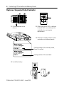
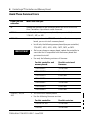
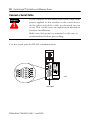
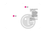
Replace a Suspected Failed Controller
1. Cycle the power to the
chassis.
2. Make sure the OK LED is solid red.
If the OK LED is not solid red, the
controller does not require
replacement.
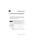
3. Match the catalog numbers of the
controllers and memory boards.
ControlLogix
CAT. NO./SERIES
1756-M…
Catalog number of the memory board,
if one is installed
ControlLogix
CAT. NO./SERIES
1756-L…
4. Install the battery.
Publication 1756-IN101H-EN-P - June 2003
Catalog number of the controller
ControlLogix™ Controller and Memory Board 5
42898
20880
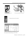
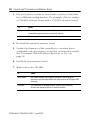
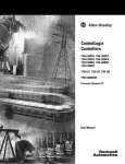
5. Insert the key and turn it to
the PROG position.
6. Insert the controller into the chassis.
7. Update the firmware of the controller.
8. Download the RSLogix 5000 project to the controller.
Publication 1756-IN101H-EN-P - June 2003
6 ControlLogix™ Controller and Memory Board
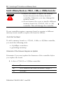
Avoid These Common Errors
If you have this
controller:
Make sure that you:
all
Update the firmware of the controller before you use it for the first
time. Controllers ship without usable firmware.
1756-L1
Install only the following memory board (one per controller):
1756-M1, -M2, or -M3
1756-L55
• If you purchased a 1756-L55 controller without a memory
board, you must install a memory board.
• Install only the following memory board (one per controller):
1756-M12, -M13, -M14, -M16, - M22, -M23, or -M24
IMPORTANT
• Before you change a memory board, update the controller to
a revision that is compatible with the memory board that
you intend to install.
• Use only the following revisions of firmware:
1756-L61, -L62, or
-L63
For this controller and
memory board:
Use this revision of
firmware:
1756-L55M12
10.x or later
1756-L55M13
6.x or later
1756-L55M14
6.x or later
1756-L55M16
6.x or later
1756-L55M22
10.x or later
1756-L55M23
8.x or later
1756-L55M24
8.x or later
• Do not install a memory board.
• Use the following firmware revision:
For this controller:
Use this revision:
1756-L61 or -L62
12.x or later
1756-L63
10.x or later
Publication 1756-IN101H-EN-P - June 2003
ControlLogix™ Controller and Memory Board 7
How to Handle ControlLogix Components
ATTENTION
!
Preventing Electrostatic Discharge
This equipment is sensitive to electrostatic
discharge, which can cause internal damage and
affect normal operation. Follow these guidelines
when you handle this equipment:
• Touch a grounded object to discharge
potential static.
• Wear an approved grounding wriststrap.
• Do not touch connectors or pins on
component boards.
• Do not touch circuit components inside the
equipment.
• If available, use a static-safe workstation.
• When not in use, store the equipment in
appropriate static-safe packaging.
Publication 1756-IN101H-EN-P - June 2003
8 ControlLogix™ Controller and Memory Board
Prepare the Chassis
Before you install a controller, do these preliminary steps:
✓
Install a ControlLogix chassis according to the ControlLogix
Chassis Installation Instructions, publication 1756-IN080.
✓
Install a ControlLogix power supply according to the
corresponding installation instructions:
Install this power supply:
According to this publication:
1756-PA72
ControlLogix Power Supplies Installation Instructions,
publication 1756-5.67
1756-PB72
1756-PA75
1756-PB75
ControlLogix Power Supplies Installation Instructions,
publication 1756-5.78
1756-PA75R
1756-PB75R
• ControlLogix Redundant Power Supplies
Installation Instructions, publication
1756-IN573
• ControlLogix Redundant Power Supplies
Chassis Adapter Module Installation
Instructions, publication 1756-IN574
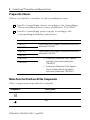
Make Sure that You Have All the Components
These components ship with the controller:
Component:
Description:
1756-BA1 battery
key
Publication 1756-IN101H-EN-P - June 2003
ControlLogix™ Controller and Memory Board 9
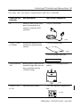
You may also use these components with the controller:
If you have this
controller:
And you want to:
Then use this component:
all
connect a device to the serial
port of the controller (e.g.,
connect a computer to the
controller)
1756-CP3 serial cable
42576
1756-L1, -L1Mx,
or -L55Mxx
increase the memory of the
controller or add nonvolatile
memory
1756-Mx memory board
40042
1756-Mx memory board label
1756-L55Mxx or
-L63
provide battery support for the
controller longer than the time
that is available with the
1756-BA1 battery
1756-BATM ControlLogix battery
module
31298
1756-L61, -L62,
or -L63
Add nonvolatile memory
1784-CF64 Industrial CompactFlash
card
31376-M
Publication 1756-IN101H-EN-P - June 2003
10 ControlLogix™ Controller and Memory Board
Install only one memory board per controller. Use the following table
to determine which memory board goes with your controller.
Use this memory
board:
With this controller:
1756-L1, -L1Mx
1756-M1
✔
1756-M2
✔
1756-M3
✔
1756-L55, -L55Mxx
1756-M12
✔
1756-M13
✔
1756-M14
✔
1756-M16
✔
1756-M22
✔
1756-M23
✔
1756-M24
✔
Publication 1756-IN101H-EN-P - June 2003
1756-L6x
ControlLogix™ Controller and Memory Board 11
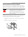
Remove the Controller from the Chassis, If Required
You can install or remove a ControlLogix controller while chassis
power is on and the system is operating. If you remove the controller,
all the devices owned by the controller go to their configured fault
state.
WARNING
!
When you insert or remove the module while
backplane power is on, an electrical arc can
occur. This could cause an explosion in
hazardous location installations. Be sure that
power is removed or the area is nonhazardous
before proceeding.
Repeated electrical arcing causes excessive wear to contacts on both
the module and its mating connector. Worn contacts may create
electrical resistance that can affect module operation.
1. On the top and bottom of the controller, press the locking
tabs.
2. Slide the controller out of the chassis.
20880
Publication 1756-IN101H-EN-P - June 2003
12 ControlLogix™ Controller and Memory Board
Install a Memory Board on a 1756-L1, -L1Mx, or -L55Mxx Controller
• Before you install or replace the memory
board, disconnect the battery from the
controller. Otherwise, you may damage the
memory board.
• Do not remove the cover or install a different
memory board of a 1756-L61, -L62, or -L63
controller. This will damage the controller.
ATTENTION
!
If your controller requires a memory board or requires a different
memory board, install or replace the board as follows:
Tools that You Need
To add a memory board to a 1756-L1, -L1Mx, or -L55Mxx controller,
you need the following tools:
• #2 phillips screwdriver
• grounding wriststrap
Determine if the Firmware Requires an Update
Determine if you must update the firmware of the controller before
you replace the board.
1. Is this a 1756-L55 or -L55Mxx controller?
If:
Then:
No
Go to “Remove the Side Plate of the Controller” on page 13.
Yes
Go to step 2.
Publication 1756-IN101H-EN-P - June 2003
ControlLogix™ Controller and Memory Board 13
2. Are you replacing a memory board with a memory board that
has a different catalog number? For example, are you
replacing a 1756-M13 memory board with a 1756-M23 memory
board?
If:
Then:
No
Go to “Remove the Side Plate of the Controller” on page 13.
Yes
Before you replace the board, update the firmware of the controller:
• Update the firmware to a revision that is compatible with
the memory board that you will install.
• See “Update the Controller” on page 30.
Remove the Side Plate of the Controller
1. Lay the controller on its side with the label facing up.
2. While wearing a grounding wriststrap, remove the two screws
that attach the side plate to the controller.
Publication 1756-IN101H-EN-P - June 2003
14 ControlLogix™ Controller and Memory Board
3. Rotate the side plate up and unhook it from the controller.
side plate
front of controller
40017
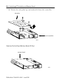
Remove the Existing Memory Board (If Any)
memory board
42527
Publication 1756-IN101H-EN-P - June 2003
ControlLogix™ Controller and Memory Board 15
1. Does the controller already have a memory board?
If:
Then:
No
Go to “Install the Memory Board” on page 16.
Yes
Go to step 2.
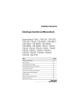
2. Pull the plastic back edge of the controller out slightly to clear
the tabs on the memory board.
tab
tab
42526
3. Gently separate and remove the memory board from the
controller.
Publication 1756-IN101H-EN-P - June 2003
16 ControlLogix™ Controller and Memory Board
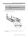
Install the Memory Board
1. Place the memory board over the connector and slide the
memory board into the controller.
memory board
tab
tab
slot
slot
40018
2. Pull the plastic back edge of the controller out slightly to clear
the tabs of the memory board.
3. Line up the connectors.
4. Place your hands on the boards over the connectors and
gently squeeze them together.
5. Make sure that the tabs on the memory board extend through
the slots on the plastic housing of the controller.
Publication 1756-IN101H-EN-P - June 2003
ControlLogix™ Controller and Memory Board 17
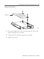
Replace the Side Plate
side plate
40019
1. Line up the hinge tabs on the side plate with the slots in the
plastic housing of the controller.
2. Gently press the side plate against the controller.
3. Replace the screws.
Publication 1756-IN101H-EN-P - June 2003
18 ControlLogix™ Controller and Memory Board
Attach Labels
Place the memory board label on the side of the controller.
The memory board label identifies which memory board is
installed.
40019
Publication 1756-IN101H-EN-P - June 2003
ControlLogix™ Controller and Memory Board 19
Install a 1784-CF64 Industrial CompactFlash Card in a 1756-L61, -L62,
or -L63 Controller
A 1784-CF64 Industrial CompactFlash card provides nonvolatile
memory for a 1756-L61, -L62, or -L63 controller. If you are using a
CompactFlash card, install the card as follows:
1. Lay the controller on its side with the front facing to the left.
2. Raise the locking clip all the way up.
31377-M
31378-M
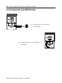
3. Insert the 1784-CF64 Industrial CompactFlash card into the
socket at the bottom of the controller.
Publication 1756-IN101H-EN-P - June 2003
20 ControlLogix™ Controller and Memory Board
4. Pull the clip forward and then downward until it snaps into
place over the card.
31379-M
Publication 1756-IN101H-EN-P - June 2003
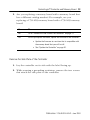
ControlLogix™ Controller and Memory Board 21
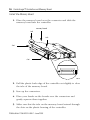
Connect a Battery
WARNING
!
When you connect or disconnect the battery an
electrical arc can occur. This could cause an
explosion in hazardous location installations. Be
sure that power is removed or the area is
nonhazardous before proceeding.
For Safety information on the handling of lithium
batteries, including handling and disposal of
leaking batteries, see Guidelines for Handling
Lithium Batteries, publication AG 5-4.
ATTENTION
!
Connect only a 1756-BA1 battery or a 1756-BATM
battery module to the controller. If you connect a
different battery, you may damage the controller.
To maintain the memory of the controller while the controller is
without power, either use nonvolatile memory or connect a battery:
If your controller:
And you want to:
Then:
has nonvolatile
memory
does not have
nonvolatile
memory
A battery is permitted but not
required.
maintain memory only while the
controller is in the chassis
Connect a 1756-BA1 battery or
a 1756-BATM battery module.
maintain memory while the
controller is out of the chassis
Connect a 1756-BA1 battery.
To connect a 1756-BATM battery module, see the ControlLogix
Battery Module Installation Instructions, publication 1756-IN576.
Publication 1756-IN101H-EN-P - June 2003
22 ControlLogix™ Controller and Memory Board
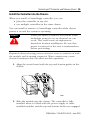
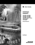
To connect a 1756-BA1 battery:
1. Install a 1756-BA1 battery.
top
no connection
middle
black lead (-)
bottom
red lead (+)
42523
2. Write on the battery label the
date you install the battery.
battery label
3. Attach the label to the inside of
the controller door.
42524
Publication 1756-IN101H-EN-P - June 2003
ControlLogix™ Controller and Memory Board 23
ATTENTION
!
ATTENTION
!
To prevent possible battery leakage, even if the
BAT LED is off, replace a 1756-BA1 battery
according to the following schedule:
If the temperature 1 in.
below the chassis is:
Replace the battery within:
0° to 35° C
No replacement is required until
the BAT LED turns on.
36° to 40° C
3 years
41° to 45° C
2 years
46° to 50° C
16 months
51° to 55° C
11 months
56° to 60° C
8 months
Store batteries in a cool, dry environment. We
recommend 25°C with 40% to 60% relative
humidity. You may store batteries for up to 30
days between -45° to 85°C, such as during
transportation. To avoid possible leakage, do not
store batteries above 60°C for more than 30 days.
Publication 1756-IN101H-EN-P - June 2003
24 ControlLogix™ Controller and Memory Board
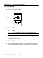
Turn the Keyswitch to the PROG Position
1. Insert the key into the
controller.
42899
2. Turn the key to the PROG
position.
42898
Publication 1756-IN101H-EN-P - June 2003
ControlLogix™ Controller and Memory Board 25
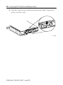
Install the Controller into the Chassis
When you install a ControlLogix controller, you can:
• place the controller in any slot
• use multiple controllers in the same chassis
You can install or remove a ControlLogix controller while chassis
power is on and the system is operating.
WARNING
!
When you insert or remove the module while
backplane power is on, an electrical arc can
occur. This could cause an explosion in
hazardous location installations. Be sure that
power is removed or the area is nonhazardous
before proceeding.
Repeated electrical arcing causes excessive wear to contacts on both
the module and its mating connector. Worn contacts may create
electrical resistance that can affect module operation.
1. Align the circuit board with the top and bottom guides in the
chassis.
20880
2. Slide the module into the chassis. The controller is fully
installed when it is flush with the power supply or other
installed modules and the top and bottom latches are engaged.
Publication 1756-IN101H-EN-P - June 2003
26 ControlLogix™ Controller and Memory Board
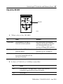
Check the BAT LED
1. Turn on the chassis power.
BAT LED
42525
2. Is the BAT LED off?
If:
Then:
Yes
Go to “Determine Which Firmware Revisions to Use” on page 29.
No
Go to step 3.
3. Check that the battery or battery module is correctly
connected to the controller.
4. If the BAT LED remains on, install another battery.
5. If the BAT LED remains on after you complete step 4, contact
your Rockwell Automation representative or local distributor.
Publication 1756-IN101H-EN-P - June 2003
ControlLogix™ Controller and Memory Board 27
Check the OK LED
OK LED
42525
1. What color is the OK LED?
If:
Then:
Actions:
solid green
The controller is OK and its
firmware has been updated.
No further actions are required.
However, the revision of firmware
must be compatible with your
revision of RSLogix 5000 software.
flashing red
The controller is OK but it requires a
firmware update.
Go to “Determine Which Firmware
Revisions to Use” on page 29.
solid red
The memory board of the controller
may not be compatible with the
revision of firmware.
Go to step 2.
2. Is this a 1756-L55 or -L55Mxx controller?
If:
Then:
No
The controller is not operational. Contact your Rockwell
Automation representative or local distributor.
Yes
Go to step 3.
Publication 1756-IN101H-EN-P - June 2003
28 ControlLogix™ Controller and Memory Board
3. Did you replace a memory board with a memory board that
has a different catalog number? For example, did you replace
a 1756-M13 memory board with a 1756-M23 memory board?
If:
Then:
No
The controller is not operational. Contact your Rockwell
Automation representative or local distributor.
Yes
Go to step 4.
4. Re-install the previous memory board.
5. Update the firmware of the controller to a revision that is
compatible with the memory board that you intend to install.
See “Determine Which Firmware Revisions to Use” on
page 29.
6. Install the new memory board.
7. What color is the OK LED?
If:
Then:
solid green
No further actions are required. However, the revision of
firmware must be compatible with your revision of RSLogix 5000
software.
solid red
The controller is not operational. Contact your Rockwell
Automation representative or local distributor.
Publication 1756-IN101H-EN-P - June 2003
ControlLogix™ Controller and Memory Board 29
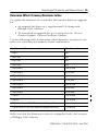
Determine Which Firmware Revisions to Use
To update the firmware of a controller, first install a firmware upgrade
kit.
• An upgrade kit ships on a supplemental CD along with
RSLogix 5000 software.
• To download an upgrade kit, go to www.ab.com. Choose
Product Support. Choose Firmware Updates.
Use the following table to determine which firmware revisions to use
with your controller and memory board combination:
For this controller and memory board:
Use this revision:
1756-L1
any
1756-L1M1
any
1756-L1M2
any
1756-L1M3
any
1756-L55M12
10.x or later
1756-L55M13
6.x or later
1756-L55M14
6.x or later
1756-L55M16
6.x or later
1756-L55M22
10.x or later
1756-L55M23
8.x or later
1756-L55M24
8.x or later
1756-L61
12.x or later
1756-L62
12.x or later
1756-L63 without a 1784-CF64 Industrial CompactFlash card
10.x or later
1756-L63 with a 1784-CF64 Industrial CompactFlash card
11.x or later
Make sure that the firmware revision is compatible with your revision
of RSLogix 5000 software.
Publication 1756-IN101H-EN-P - June 2003
30 ControlLogix™ Controller and Memory Board
Update the Controller
RSLogix 5000 software, revision 10.0 or later, lets
you update the firmware of a controller as part of
the download sequence. To update the controller,
download your project and follow the prompts of
the software.
TIP
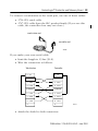
1. Connect the controller or chassis to the same network as your
workstation.
2. Start ControlFLASH software.
3. Choose Next >.
4. Select the catalog number of the controller and choose Next >.
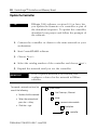
5. Expand the network until you see the controller.
IMPORTANT
If the required network is not shown, first
configure a driver for the network in RSLinx
software.
To expand a network one level, do
one of the following:
−
• Double-click the network.
• Select the network and
press the → key.
• Click the + sign.
Workstation
+
Linx Gateways, Ethernet
−
driver
−
communication module
−
backplane
+
Publication 1756-IN101H-EN-P - June 2003
controller
ControlLogix™ Controller and Memory Board 31
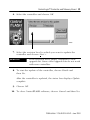
6. Select the controller and choose OK.
42900
7. Select the revision level to which you want to update the
controller and choose Next >.
IMPORTANT
If the Revision list is empty, download a new
upgrade kit. Some older upgrade kits do not work
with new controllers.
8. To start the update of the controller, choose Finish and
then Yes.
After the controller is updated, the status box displays Update
complete.
9. Choose OK.
10. To close ControlFLASH software, choose Cancel and then Yes.
Publication 1756-IN101H-EN-P - June 2003
32 ControlLogix™ Controller and Memory Board
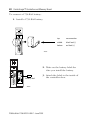
Connect a Serial Cable
WARNING
!
If you connect or disconnect the serial cable with
power applied to this module or the serial device
on the other end of the cable, an electrical arc can
occur. This could cause an explosion in hazardous
location installations.
Make sure that power is removed or the area is
nonhazardous before proceeding.
Use the serial port for RS-232 communication.
42575
serial port
Publication 1756-IN101H-EN-P - June 2003
ControlLogix™ Controller and Memory Board 33
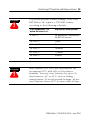
To connect a workstation to the serial port, use one of these cables:
• 1756-CP3 serial cable
• 1747-CP3 cable from the SLC product family (If you use this
cable, the controller door may not close.)
workstation end
controller end
42576
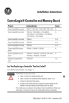
If you make your own serial cable:
• Limit the length to 15.2m (50 ft).
• Wire the connectors as follows:
Workstation
Controller
1 CD
1 CD
2 RDX
2 RDX
3 TXD
3 TXD
4 DTR
4 DTR
COMMON
COMMON
6 DSR
6 DSR
7 RTS
7 RTS
8 CTS
8 CTS
9
9
42231
• Attach the shield to both connectors
Publication 1756-IN101H-EN-P - June 2003
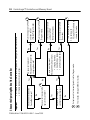
Publication 1756-IN101H-EN-P - June 2003
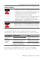
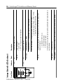
B
Yes
No
Do you want to prevent
RSLogix 5000 software from:
• changing the mode
• downloading a project
• performing online edits
Do you want to prevent
RSLogix 5000 software from
changing the mode?
B This includes Message (MSG) instructions.
A Outputs revert to their configured state for Program mode.
No
Do you want the logic to
control the output devices?
Yes
Do you want to execute the
logic in the controller?
No
Yes
Yes
No
Yes
No
1. Turn the keyswitch to REM.
2. Go online with
RSLogix 5000 software and
choose Test mode.
Turn the keyswitch to RUN
(Run mode).
Turn the keyswitch to RUN
and then to REM
(Remote Run mode).
Turn the keyswitch to PROG
(Program mode).
Turn the keyswitch to PROG
and then to REM
(Remote Program mode).
• All modes send and receive data in response to a message from another controller.
• All modes produce and consume tags.
Do you need to schedule a
ControlNet network?
Important
Choose the Operating Mode of the Controller
A
A
A
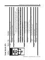
34 ControlLogix™ Controller and Memory Board
Front Panel:
RS232
FORCE
I/O
RUN
Indicator:
Interpret Controller LEDs
There is no activity.
Data is being received or transmitted
solid green
One or more input or output addresses have been forced to an On or Off state, but
the forces have not been enabled.
off
flashing
amber
• I/O forces are active (enabled).
• I/O force values may or may not exist.
The chassis is bad. Replace the chassis.
solid amber
One or more devices in the I/O configuration of the controller are not responding.
flashing green
flashing red
• No tags contain I/O force values.
• I/O forces are inactive (disabled).
The controller is communicating with all the devices in its I/O configuration.
solid green
off
Either:
• There are no devices in the I/O configuration of the controller.
• The controller does not contain a project (controller memory is empty).
off
The controller is in Program or Test mode.
The controller is in Run mode.
off
Description:
solid green
Color:
ControlLogix™ Controller and Memory Board 35
Publication 1756-IN101H-EN-P - June 2003
Front Panel:
OK
BAT
Indicator:
Publication 1756-IN101H-EN-P - June 2003
The controller is OK
The controller is storing or loading a project to or from nonvolatile memory.
flashing green
not a new controller
solid green
Major fault occurred. To clear the fault, either:
• Turn the keyswitch ⇒ PROG ⇒ RUN ⇒ PROG.
• Go online with RSLogix 5000 software.
a new controller
The controller detected a non-recoverable fault, so it cleared the project from
memory. To recover:
1. Cycle power to the chassis.
2. Download the project.
3. Change to Run mode.
If the OK LED remains solid red, contact your Rockwell Automation representative or
local distributor.
The controller requires a firmware update.
If the controller is:
flashing red
solid red
Then:
No power is applied.
Either the battery is:
• not installed.
• 95% discharged and should be replaced.
off
The battery supports memory.
solid red
Description:
off
Color:
Interpret Controller LEDs Continued
36 ControlLogix™ Controller and Memory Board
1M bytes
2M bytes
750K bytes
1.5M bytes
3.5M bytes
7.5M bytes
(≤ 3.5M of data)
1756-L1M3
1756-L55M12
1756-L55M13
1756-L55M14
1756-L55M16
(2)
208K bytes
208K bytes
208K bytes
208K bytes
150K bytes
150K bytes
150K bytes
(2)
No
No
No
No
No
No
No
No
Nonvolatile
Memory
1.48A
1.25A
1.23A
1.23A
1.20A
1.05A
0.95A
0.65A
@ 5.1V
dc
0.014A
0.014A
0.014A
0.014A
0.02A
0.02A
0.02A
0.02A
@ 24V dc
Backplane Current
6.3W
5.7W
5.6W
5.6W
5.4W
4.8W
4.6W
3.3W
Power
Dissipation
21.5 BTU/hr
19.4 BTU/hr
19.1 BTU/hr
19.1 BTU/hr
18.4 BTU/hr
16.4 BTU/hr
15.6 BTU/hr
11.3 BTU/hr
Thermal
Dissipation
0.38 kg (13.4 oz)
0.36 kg (12.8 oz)
0.35 kg (12.5 oz)
0.35 kg (12.5 oz)
0.36 kg (12.7 oz)
0.35 kg (12.5 oz)
0.35 kg (12.5 oz)
0.28 kg (10.0 oz)
Weight
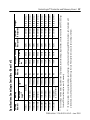
I/O memory stores: I/O tags, produced tags, consumed tags, communication via Message (MSG) instructions, communication with
workstations, and communication with OPC/DDE tags that use RSLinx software (also uses data and logic memory).
Data and logic memory stores: tags other than I/O, produced, or consumed tags; logic routines; and communication with OPC/DDE tags
that use RSLinx software (also uses I/O memory)
500K bytes
(1)
I/O
64K bytes
1756-L1M2
Data and
Logic(1)
Memory
1756-L1M1
1756-L1
Catalog
Number
Specifications: ControlLogix Controllers - Sheet 1 of 2
ControlLogix™ Controller and Memory Board 37
Publication 1756-IN101H-EN-P - June 2003
Publication 1756-IN101H-EN-P - June 2003
3.5M bytes
2M bytes
4M bytes
8M bytes
1756-L55M24
1756-L61
1756-L62
1756-L63
(3)
(2)
478K bytes
478K bytes
478K bytes
208K bytes
208K bytes
208K bytes
I/O
(2)
Yes(3)
Yes
Yes
Yes
Nonvolatile
Memory
1.20A
1.25A
1.23A
1.23A
@ 5.1V
dc
14mA
0.014A
0.014A
0.014A
@ 24V dc
Backplane Current
3.5W
5.7W
5.6W
5.6W
Power
Dissipation
11.9 BTU/hr
19.4 BTU/hr
19.1 BTU/hr
19.1 BTU/hr
Thermal
Dissipation
0.32 kg (11.3 oz)
0.36 kg (12.8 oz)
0.35 kg (12.5 oz)
0.35 kg (12.5 oz)
Weight
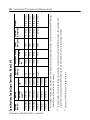
Requires a 1784-CF64 Industrial CompactFlash card.
I/O memory stores: I/O tags, produced tags, consumed tags, communication via Message (MSG) instructions, communication with
workstations, and communication with OPC/DDE tags that use RSLinx software (also uses data and logic memory).
Data and logic memory stores: tags other than I/O, produced, or consumed tags; logic routines; and communication with OPC/DDE tags
that use RSLinx software (also uses I/O memory)
1.5M bytes
1756-L55M23
(1)
750K bytes
Data and
Logic(1)
Memory
1756-L55M22
Catalog
Number
Specifications: ControlLogix Controllers - Sheet 2 of 2
38 ControlLogix™ Controller and Memory Board
ControlLogix™ Controller and Memory Board 39
The following specifications apply to all ControlLogix controllers:
Description:
Value:
Operating Temperature
IEC 60068-2-1 (Test Ad, Operating Cold),
IEC 60068-2-2 (Test Bd, Operating Dry Heat),
IEC 60068-2-14 (Test Nb, Operating Thermal Shock):
• 0° to 60° C (32 to 140° F)
Storage Temperature
IEC 60068-2-1 (Test Ab, Un-packaged Non-operating Cold),
IEC 60068-2-2 (Test Bb, Un-packaged Non-operating Dry Heat),
IEC 60068-2-14 (Test Na, Un-packaged Non-operating Thermal Shock):
• -40° to 85° C (-40 to 185° F)
Relative Humidity
IEC 60068-2-30 (Test Db, Un-packaged Non-operating
Damp Heat):
• 5% to 95% noncondensing
Vibration
IEC60068-2-6 (Test Fc, Operating):
• 2g @ 10-500Hz
Operating Shock
IEC60068-2-27 (Test Ea, Unpackaged Shock):
• 30g
Non-Operating Shock
IEC60068-2-27 (Test Ea, Unpackaged Shock):
• 50g
Emissions
CISPR 11:
• Group 1, Class A
ESD Immunity
IEC 61000-4-2:
• 6kV contact discharges
• 8kV air discharges
Radiated RF Immunity
IEC 61000-4-3:
• 10V/m with 1kHz sine-wave 80%AM from 30MHz to 2000MHz
• 10V/m with 200Hz 50% Pulse 100%AM at 900Mhz
EFT/B immunity
IEC 61000-4-4:
• ±4kV at 2.5kHz on power ports
• ±4kV at 2.5kHz on communications ports
Surge Transient Immunity
IEC 61000-4-5:
• ±2kV line-earth(CM) on shielded ports
Conducted RF Immunity
IEC 61000-4-6:
• 10Vrms with 1kHz sine-wave 80%AM from 150kHz to 80MHz
Enclosure Type Rating
none (open-style)
Publication 1756-IN101H-EN-P - June 2003
40 ControlLogix™ Controller and Memory Board
Description:
Value:
Isolation Voltage
30V
Tested to withstand 500 Volts for 60 seconds
Programming Cable
1756-CP3 or 1747-CP3 serial cable
category 3(1)
Replacement Battery
(1)
For this component:
Use this battery:
1756-Lx controller
1756-BA1 (0.59g lithium)
1756-BATM battery module
1756-BATA (10g lithium)
See Industrial Automation Wiring and Grounding Guidelines, publication 1770-4.1.
Certifications - Controllers and Memory Boards
When marked, the components have the following certifications. For
CE, C-Tick, and EEX, see the Product Certification link at
www.ab.com for Declarations of Conformity, Certificates, and other
certification details.
1756-L1 and -L55 Controller
Certification:
Description
UL
UL Listed Industrial Control Equipment
CSA
CSA Certified Process Control Equipment
CSA
CSA Certified Process Control Equipment for Class I, Division 2 Group A,B,C,D
Hazardous Locations
CE
European Union 89/336/EEC EMC Directive, compliant with:
• EN 61000-6-4; Industrial Emissions
• EN 50082-2; Industrial Immunity
• EN 61326; Meas./Control/Lab., Industrial Requirements
• EN 61000-6-2; Industrial Immunity
C-Tick
Australian Radiocommunications Act, compliant with:
AS/NZS CISPR 11; Industrial Emissions
EEx
European Union 94/9/EEC ATEX Directive, compliant with:
EN 50021; Potentially Explosive Atmospheres, Protection “n”
Publication 1756-IN101H-EN-P - June 2003
ControlLogix™ Controller and Memory Board 41
1756-L61, -L62, and -L63 Controller
Certification:
Description
UL
UL Listed Industrial Control Equipment
CSA
CSA Certified Process Control Equipment
CSA
CSA Certified Process Control Equipment for Class I, Division 2 Group A,B,C,D
Hazardous Locations
FM
FM Approved Equipment for use in Class I Division 2 Group A,B,C,D Hazardous
Locations
CE
European Union 89/336/EEC EMC Directive, compliant with:
• EN 61000-6-4; Industrial Emissions
• EN 50082-2; Industrial Immunity
• EN 61326; Meas./Control/Lab., Industrial Requirements
• EN 61000-6-2; Industrial Immunity
C-Tick
Australian Radiocommunications Act, compliant with:
AS/NZS CISPR 11; Industrial Emissions
EEx
European Union 94/9/EEC ATEX Directive, compliant with:
EN 50021; Potentially Explosive Atmospheres, Protection “n”
1756-Mx Memory Board
Certification:
Description
UR
UL Recognized Component Industrial Control Equipment
CSA
CSA Accepted Component for Process Control Equipment
CSA
CSA Accepted Component for Process Control Equipment in Class I, Division 2
Group A,B,C,D Hazardous Locations
CE
European Union 89/336/EEC EMC Directive, compliant with:
• EN 61000-6-4; Industrial Emissions
• EN 50082-2; Industrial Immunity
• EN 61326; Meas./Control/Lab., Industrial Requirements
• EN 61000-6-2; Industrial Immunity
C-Tick
Australian Radiocommunications Act, compliant with:
AS/NZS CISPR 11; Industrial Emissions
EEx
European Union 94/9/EEC ATEX Directive, compliant with:
EN 50021; Potentially Explosive Atmospheres, Protection “n”
Publication 1756-IN101H-EN-P - June 2003
42 ControlLogix™ Controller and Memory Board
Specifications and Certifications - 1784-CF64 Industrial
CompactFlash Card
For CE and C-Tick, see the Product Certification link at www.ab.com
for Declarations of Conformity, Certificates, and other certification
details.
Description:
Value:
User Available Memory
64M bytes
Nonvolatile Memory
Yes
Weight
14.2 g (0.5 oz).
Operating Temperature
IEC 60068-2-1 (Test Ad, Operating Cold),
IEC 60068-2-2 (Test Bd, Operating Dry Heat),
IEC 60068-2-14 (Test Nb, Operating Thermal Shock):
• 0 to 60°C (32 to 140°F)
Storage Temperature
IEC 60068-2-1 (Test Ab, Un-packaged Non-operating Cold),
IEC 60068-2-2 (Test Bb, Un-packaged Non-operating Dry Heat),
IEC 60068-2-14 (Test Na, Un-packaged Non-operating Thermal Shock):
• -40 to 85°C (-40 to 185°F)
Relative Humidity
IEC 60068-2-30 (Test Db, Un-packaged Non-operating
Damp Heat):
• 5% to 95% noncondensing
Vibration
IEC60068-2-6 (Test Fc, Operating):
• 2g @ 10-500Hz
Operating Shock
IEC60068-2-27 (Test Ea, Unpackaged Shock):
• 30g
Non-Operating Shock
IEC60068-2-27 (Test Ea, Unpackaged Shock):
• 50g
ESD Immunity
IEC 61000-4-2:
• 4kV contact discharges
• 8kV air discharges
Radiated RF Immunity
IEC 61000-4-3:
• 10V/m with 1kHz sine-wave 80%AM from 80MHz to 1000MHz
EFT/B immunity
IEC 61000-4-4:
• ±4kV at 2.5kHz on power ports
Publication 1756-IN101H-EN-P - June 2003
ControlLogix™ Controller and Memory Board 43
Description:
Value:
Conducted RF Immunity
IEC 61000-4-6:
• 10Vrms with 1kHz sine-wave 80%AM from 150kHz to 80MHz
Enclosure Type Rating
none (open-style)
Emissions
CISPR 11:
• Group 1, Class A
Certifications:
(when product is
marked)
CE
C-Tick
European Union 89/336/EEC EMC Directive,
compliant with:
• EN61000-6-4; Industrial Emissions
• EN 50082-2; Industrial Immunity
• EN 61326; Meas./Control/Lab., Industrial
Requirements
• EN 61000-6-2; Industrial Immunity
Australian Radiocommunications Act, compliant with:
AS/NZS CISPR 11; Industrial Emissions
Publication 1756-IN101H-EN-P - June 2003
44 ControlLogix™ Controller and Memory Board
Environment and Enclosure Information
ATTENTION
!
Environment and Enclosure
This equipment is intended for use in a Pollution Degree 2 industrial
environment, in overvoltage Category II applications (as defined in IEC
publication 60664-1), at altitudes up to 2000 meters without derating.
This equipment is considered Group 1, Class A industrial equipment
according to IEC/CISPR Publication 11. Without appropriate
precautions, there may be potential difficulties ensuring
electromagnetic compatibility in other environments due to conducted
as well as radiated disturbance.
This equipment is supplied as "open type" equipment. It must be
mounted within an enclosure that is suitably designed for those
specific environmental conditions that will be present and
appropriately designed to prevent personal injury resulting from
accessibility to live parts. The interior of the enclosure must be
accessible only by the use of a tool. Subsequent sections of this
publication may contain additional information regarding specific
enclosure type ratings that are required to comply with certain
product safety certifications.
See NEMA Standards publication 250 and IEC publication 60529, as
applicable, for explanations of the degrees of protection provided by
different types of enclosure. Also, see the appropriate sections in this
publication, as well as the Allen-Bradley publication 1770-4.1
("Industrial Automation Wiring and Grounding Guidelines"), for
additional installation requirements pertaining to this equipment.
Publication 1756-IN101H-EN-P - June 2003
ControlLogix™ Controller and Memory Board 45
European Hazardous Location Approval
European Zone 2 Certification - 1756-L1, -L1M1, -L1M2,
-L1M3, -L55M13, -L55M14, -L55M16, -L61, -L62, and -L63
Controllers
This equipment is intended for use in potentially explosive
atmospheres as defined by European Union Directive 94/9/CE.
The LCIE (Laboratoire Central des Industries Electriques) certifies
that this equipment has been found to comply with the Essential
Health and Safety Requirements relating to the design and
construction of Category 3 equipment intended for use in
potentially explosive atmospheres, given in Annex II to this
Directive. The examination and test results are recorded in
confidential report No. 28 682 010.
Compliance with the Essential Health and Safety Requirements has
been assured by compliance with EN 50021.
IMPORTANT
• This equipment is not resistant to sunlight or other sources
of UV radiation.
• The secondary of a current transformer shall not be
open-circuited when applied in Class I, Zone 2 environments.
• Equipment of lesser Enclosure Type Rating must be installed
in an enclosure providing at least IP54 protection when
applied in Class I, Zone 2 environments.
• This equipment shall be used within its specified ratings
defined by Allen-Bradley.
• Provision shall be made to prevent the rated voltage from
being exceeded by transient disturbances of more than 40%
when applied in Class I, Zone 2 environments.
Publication 1756-IN101H-EN-P - June 2003
46 ControlLogix™ Controller and Memory Board
North American Hazardous Location Approval
The following information applies when
operating this equipment in hazardous
locations:
Informations sur l’utilisation de cet équipement
en environnements dangereux :
Products marked “CL I, DIV 2, GP A, B, C, D” are
suitable for use in Class I Division 2 Groups A, B,
C, D, Hazardous Locations and nonhazardous
locations only. Each product is supplied with
markings on the rating nameplate indicating the
hazardous location temperature code. When
combining products within a system, the most
adverse temperature code (lowest “T” number)
may be used to help determine the overall
temperature code of the system. Combinations
of equipment in your system are subject to
investigation by the local Authority Having
Jurisdiction at the time of installation.
Les produits marqués "CL I, DIV 2, GP A, B, C, D" ne
conviennent qu’à une utilisation en environnements
de Classe I Division 2 Groupes A, B, C, D dangereux et
non dangereux. Chaque produit est livré avec des
marquages sur sa plaque d’identification qui
indiquent le code de température pour les
environnements dangereux. Lorsque plusieurs
produits sont combinés dans un système, le code de
température le plus défavorable (code de température
le plus faible) peut être utilisé pour déterminer le
code de température global du système. Les
combinaisons d’équipements dans le système sont
sujettes à inspection par les autorités locales
qualifiées au moment de l’installation.
WARNING
!
EXPLOSION HAZARD
• Do not disconnect
equipment unless power
has been removed or the
area is known to be
nonhazardous.
• Do not disconnect
connections to this
equipment unless power
has been removed or the
area is known to be
nonhazardous. Secure any
external connections that
mate to this equipment by
using screws, sliding
latches, threaded
connectors, or other
means provided with this
product.
• Substitution of
components may impair
suitability for Class I,
Division 2.
• If this product contains
batteries, they must only
be changed in an area
known to be
nonhazardous.
Publication 1756-IN101H-EN-P - June 2003
AVERTISSEMENT
!
RISQUE D’EXPLOSION
• Couper le courant ou
s’assurer que
l’environnement est classé
non dangereux avant de
débrancher l'équipement.
• Couper le courant ou
s'assurer que
l’environnement est classé
non dangereux avant de
débrancher les
connecteurs. Fixer tous les
connecteurs externes
reliés à cet équipement à
l'aide de vis, loquets
coulissants, connecteurs
filetés ou autres moyens
fournis avec ce produit.
• La substitution de
composants peut rendre
cet équipement inadapté à
une utilisation en
environnement de Classe I,
Division 2.
• S’assurer que
l’environnement est classé
non dangereux avant de
changer les piles.
ControlLogix™ Controller and Memory Board 47
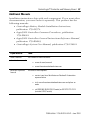
Additional Manuals
Installation instructions ship with each component. If you want other
documentation, you must order it separately. This product has the
following manuals:
• ControlLogix Battery Module Installation Instructions,
publication 1756-IN576
• Logix5000 Controllers Common Procedures, publication
1756-PM001
• Logix5000 Controllers General Instructions Reference Manual,
publication 1756-RM003
• ControlLogix System User Manual, publication 1756-UM001
If you want to:
Then:
view a manual
Visit either of these locations:
download a manual
• www.ab.com/manuals
• www.theautomationbookstore.com
purchase a printed
manual
Use one of these options:
• contact your local distributor or Rockwell Automation
representative
• visit www.theautomationbookstore.com and place an
order
• call 800.963.9548 (USA/Canada) or 001.320.725.1574
(outside USA/Canada)
Publication 1756-IN101H-EN-P - June 2003
Rockwell Automation Support
Rockwell Automation provides technical information on the web to assist you
in using our products. At http://support.rockwellautomation.com, you can
find technical manuals, a knowledge base of FAQs, technical and application
notes, sample code and links to software service packs, and a MySupport
feature that you can customize to make the best use of these tools.
For an additional level of technical phone support for installation,
configuration and troubleshooting, we offer TechConnect Support programs.
For more information, contact your local distributor or Rockwell Automation
representative, or visit http://support.rockwellautomation.com.
Installation Assistance
If you experience a problem with a hardware module within the first 24 hours
of installation, please review the information that's contained in this manual.
You can also contact a special Customer Support number for initial help in
getting your module up and running:
United States
1.440.646.3223 Monday – Friday, 8am – 5pm EST
Outside United States
Please contact your local Rockwell Automation representative for any
technical support issues.
New Product Satisfaction Return
Rockwell tests all of our products to ensure that they are fully operational
when shipped from the manufacturing facility. However, if your product is not
functioning and needs to be returned:
United States
Contact your distributor. You must provide a Customer Support case number
(see phone number above to obtain one) to your distributor in order to
complete the return process.
Outside United States
Please contact your local Rockwell Automation representative for return
procedure.
Back Cover
Publication 1756-IN101H-EN-P - June 2003
Supersedes Publication 1756-IN101G-EN-P - November 2002
PN 957782-40
Copyright © 2003 Rockwell Automation, Inc. All rights reserved. Printed in the U.S.A.